US12228809B2 - Display module, display device and calculation method - Google Patents
Display module, display device and calculation method Download PDFInfo
- Publication number
- US12228809B2 US12228809B2 US18/027,532 US202218027532A US12228809B2 US 12228809 B2 US12228809 B2 US 12228809B2 US 202218027532 A US202218027532 A US 202218027532A US 12228809 B2 US12228809 B2 US 12228809B2
- Authority
- US
- United States
- Prior art keywords
- segment
- transition curve
- circular arc
- value
- curve
- Prior art date
- Legal status (The legal status is an assumption and is not a legal conclusion. Google has not performed a legal analysis and makes no representation as to the accuracy of the status listed.)
- Active
Links
- 238000004364 calculation method Methods 0.000 title claims description 19
- 230000007704 transition Effects 0.000 claims abstract description 200
- 230000010354 integration Effects 0.000 claims description 7
- 238000005452 bending Methods 0.000 description 18
- 230000000694 effects Effects 0.000 description 11
- 238000000034 method Methods 0.000 description 5
- NIXOWILDQLNWCW-UHFFFAOYSA-N acrylic acid group Chemical group C(C=C)(=O)O NIXOWILDQLNWCW-UHFFFAOYSA-N 0.000 description 2
- 239000002131 composite material Substances 0.000 description 2
- 230000003247 decreasing effect Effects 0.000 description 2
- 238000010586 diagram Methods 0.000 description 2
- 239000002184 metal Substances 0.000 description 2
- 238000012986 modification Methods 0.000 description 2
- 230000004048 modification Effects 0.000 description 2
- 230000003287 optical effect Effects 0.000 description 2
- 238000005516 engineering process Methods 0.000 description 1
- 239000011521 glass Substances 0.000 description 1
- 230000017525 heat dissipation Effects 0.000 description 1
- 238000010438 heat treatment Methods 0.000 description 1
- 238000009434 installation Methods 0.000 description 1
- 239000004973 liquid crystal related substance Substances 0.000 description 1
- 239000000463 material Substances 0.000 description 1
- 239000004033 plastic Substances 0.000 description 1
- 230000000750 progressive effect Effects 0.000 description 1
- 239000002994 raw material Substances 0.000 description 1
- 238000002310 reflectometry Methods 0.000 description 1
- 230000008093 supporting effect Effects 0.000 description 1
Images


Classifications
-
- G—PHYSICS
- G02—OPTICS
- G02F—OPTICAL DEVICES OR ARRANGEMENTS FOR THE CONTROL OF LIGHT BY MODIFICATION OF THE OPTICAL PROPERTIES OF THE MEDIA OF THE ELEMENTS INVOLVED THEREIN; NON-LINEAR OPTICS; FREQUENCY-CHANGING OF LIGHT; OPTICAL LOGIC ELEMENTS; OPTICAL ANALOGUE/DIGITAL CONVERTERS
- G02F1/00—Devices or arrangements for the control of the intensity, colour, phase, polarisation or direction of light arriving from an independent light source, e.g. switching, gating or modulating; Non-linear optics
- G02F1/01—Devices or arrangements for the control of the intensity, colour, phase, polarisation or direction of light arriving from an independent light source, e.g. switching, gating or modulating; Non-linear optics for the control of the intensity, phase, polarisation or colour
- G02F1/13—Devices or arrangements for the control of the intensity, colour, phase, polarisation or direction of light arriving from an independent light source, e.g. switching, gating or modulating; Non-linear optics for the control of the intensity, phase, polarisation or colour based on liquid crystals, e.g. single liquid crystal display cells
- G02F1/133—Constructional arrangements; Operation of liquid crystal cells; Circuit arrangements
- G02F1/1333—Constructional arrangements; Manufacturing methods
- G02F1/133308—Support structures for LCD panels, e.g. frames or bezels
- G02F1/133314—Back frames
-
- G—PHYSICS
- G02—OPTICS
- G02F—OPTICAL DEVICES OR ARRANGEMENTS FOR THE CONTROL OF LIGHT BY MODIFICATION OF THE OPTICAL PROPERTIES OF THE MEDIA OF THE ELEMENTS INVOLVED THEREIN; NON-LINEAR OPTICS; FREQUENCY-CHANGING OF LIGHT; OPTICAL LOGIC ELEMENTS; OPTICAL ANALOGUE/DIGITAL CONVERTERS
- G02F1/00—Devices or arrangements for the control of the intensity, colour, phase, polarisation or direction of light arriving from an independent light source, e.g. switching, gating or modulating; Non-linear optics
- G02F1/01—Devices or arrangements for the control of the intensity, colour, phase, polarisation or direction of light arriving from an independent light source, e.g. switching, gating or modulating; Non-linear optics for the control of the intensity, phase, polarisation or colour
- G02F1/13—Devices or arrangements for the control of the intensity, colour, phase, polarisation or direction of light arriving from an independent light source, e.g. switching, gating or modulating; Non-linear optics for the control of the intensity, phase, polarisation or colour based on liquid crystals, e.g. single liquid crystal display cells
- G02F1/133—Constructional arrangements; Operation of liquid crystal cells; Circuit arrangements
- G02F1/1333—Constructional arrangements; Manufacturing methods
- G02F1/1335—Structural association of cells with optical devices, e.g. polarisers or reflectors
- G02F1/133524—Light-guides, e.g. fibre-optic bundles, louvered or jalousie light-guides
-
- G—PHYSICS
- G09—EDUCATION; CRYPTOGRAPHY; DISPLAY; ADVERTISING; SEALS
- G09F—DISPLAYING; ADVERTISING; SIGNS; LABELS OR NAME-PLATES; SEALS
- G09F9/00—Indicating arrangements for variable information in which the information is built-up on a support by selection or combination of individual elements
- G09F9/30—Indicating arrangements for variable information in which the information is built-up on a support by selection or combination of individual elements in which the desired character or characters are formed by combining individual elements
- G09F9/302—Indicating arrangements for variable information in which the information is built-up on a support by selection or combination of individual elements in which the desired character or characters are formed by combining individual elements characterised by the form or geometrical disposition of the individual elements
Definitions
- the present disclosure relates to the display technology, and particularly relates to a display module, display device and calculation method.
- the periphery of the display panel is slightly deformed, and in the case of aspheric bending of the display panel, that is, the display surface of the curved display panel includes an arc surface and a flat surface, the area where light leakage occurs is located in the critical position between the arc surface and the flat surface of the display panel, thereby resulting in a decrease in the display effect of the display module.
- Embodiments of the present disclosure provide a display module, display device and calculation method.
- an embodiment of the present application provides a display module, including a back plate, a light guide plate fixed on the back plate, a rubber frame attached on the back plate and a display panel disposed on the rubber frame;
- the back plate includes a bearing surface and a back surface opposite to the bearing surface;
- the light guide plate is fixed on the bearing surface, a connecting line between two end portions of the bearing surface forms a first curve, the first curve includes at least a circular arc segment and a transition curve segment, and the first curve bends in a direction away from the display panel;
- the circular arc segment is located at a middle of the first curve, and at least one end of the circular arc segment is provided with the transition curve segment;
- the transition curve segment is located at a first position of the bearing surface, the first position being a position of the bearing surface opposite to a second position of the display panel, and the second position being a position where light leaks from the display panel, and a radius of curvature of the transition curve segment gradually increases along a direction close to an end
- the first curve includes a first transition curve segment and a second transition curve segment; the first transition curve segment and the second transition curve segment are respectively located at both ends of the circular arc segment, and the first transition curve segment and the second transition curve segment are both located at a position of the bearing surface.
- the first curve further includes a first straight line segment and a second straight line segment; the first straight line segment is located at an end portion of the first transition curve segment, the second straight line segment is located at an end portion of the second transition curve segment, and the first straight line segment and the second straight line segment are respectively located at both end portions of the first curve.
- the first straight line segment is tangent to an end point of the first transition curve segment distal to the circular arc segment; the second straight line segment is tangent to an end point of the second transition curve segment distal to the circular arc segment.
- first transition curve segment and the second transition curve segment are symmetrically distributed on both sides of the circular arc segment, and a center of the circular arc segment coincides with a center of the first curve.
- a radius of curvature of the first transition curve segment at a first point is equal to a radius of curvature of the second transition curve segment at a second point; a distance between the first point and the center point of the circular arc segment is equal to a distance between the second point and the center point of the circular arc segment.
- an arc length of the circular arc segment is equal to one quarter of an arc length of the first curve.
- an arc length of the transition curve segment is equal to three-eighths of an arc length of the first curve.
- an embodiment of the present application provides a display device including the display module described in any embodiments of the first aspect.
- an embodiment of the present application provides a calculation method for calculating the first curve according to the first aspect.
- the calculation method includes:
- the determining a value of the cubic parabolic constant of the transition curve segment based on a first value includes:
- the expansion expression is:
- the determining a value of the cubic parabolic constant of the transition curve segment based on a first value includes:
- the expansion expression is:
- R c ⁇ ( 1 + x 4 4 ⁇ c 2 ) 3 2 x ,
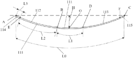
- FIG. 1 is a schematic structural diagram illustrating a back plate included in a display module provided by an embodiment of the present disclosure
- FIG. 2 is a first schematic flow chart of a calculation method provided by an embodiment of the present disclosure
- FIG. 3 is a second schematic flow chart of a calculation method provided by an embodiment of the present disclosure.
- FIG. 4 is a third schematic flow chart of a calculation method provided by an embodiment of the present disclosure.
- FIG. 5 is a parabolic curve graph of a transition curve segment provided by an embodiment of the present disclosure.
- FIG. 1 is a schematic structural diagram illustrating a back plate included in a display module provided by an embodiment of the present disclosure.
- the embodiment of the present disclosure provides a display module, including a back plate 1 , a light guide plate fixed on the back plate 1 , a rubber frame attached on the back plate 1 and a display panel located on the rubber frame.
- the back plate 1 includes a bearing surface 11 and a back surface opposite to the bearing surface 11 ;
- the light guide plate is fixed on the bearing surface 11 , a connecting line between two end portions of the bearing surface 11 forms a first curve, the first curve at least includes a circular arc segment 111 and a transition curve segment, and the first curve bends in a light emitting direction away from the display panel;
- the circular arc segment 111 is located at the middle of the first curve, and at least one end of the circular arc segment 111 is provided with a transition curve segment;
- the transition curve segment is located at a first position of the bearing surface 11 , the first position being a position of the bearing surface 11 opposite to a second position of the display panel, and the second position being a position where light leaks from the display panel is located, and the radius of curvature of the transition curve gradually increases along the direction close to an end portion of the first curve.
- the light guide plate uses an acrylic plate of optical grade as a basic raw material, and then a material having a very high reflectivity and not absorbing light is used to print light guide spots on the bottom surface of the acrylic plate of optical grade, so that the light guide plate may absorb the light emitted from the light emitting assembly.
- the back plate 1 is a device for providing support for a display panel.
- the back plate 1 may be any of a stamped metal back plate, a glass back plate and a composite material back plate.
- the back plate 1 may be a composite material back plate 1 . During installation, it is necessary to control the gap between the heating element and the back plate 1 in the display module so as to ensure heat transfer.
- the periphery of the display panel is slightly deformed, so that the liquid crystal in the display panel is locally distorted, and dark state light leakage occurs under a black picture of the display panel.
- the area where light leakage occurs is generally located in a critical position between the arc surface and the flat surface of the display panel.
- the back plate 1 includes the bearing surface 11 and a back surface opposite to the bearing surface 11 ; the light guide plate is fixed on the bearing surface 11 , a connecting line between two end portions of the bearing surface 11 forms a first curve, that is, the top portion of the cross-section of the back plate 1 in a direction perpendicular to the display surface of the display panel is a first curve, and the first curve is bent in the light emitting direction away from the display panel.
- the bending direction of the first curve coincides with the bending direction of the display panel.
- the first curve includes at least a circular arc segment 111 and a transition curve segment
- the circular arc segment 111 is a circular arc curve with a same radius of curvature
- the transition curve segment is a parabolic curve with gradually changed radius of curvature, which gradually increases in a direction close to the end portion of the first curve.
- the circular arc segment 111 is located at the middle of the first curve, that is, a midpoint of the circular arc segment 111 coincides with the midpoint of the first curve.
- At least one end of the circular arc segment 111 is provided with a transition curve segment, that is, the transition curve segment may include one segment or two segments, and the embodiments of the present disclosure are not limited thereto.
- transition curve segment is located at a first position of the bearing surface 11 , the first position being a position of the bearing surface 11 opposite to a second position of the display panel, and the second position being a position where the area where light leaks from the display panel, the transition curve segment and the area where light leaks from the display panel are located at opposite positions, as such, the stress generated at the critical position between the arc surface and the flat surface of the display panel in the case of aspheric bending of the display panel may be dispersed by the transition curve segment, thereby avoiding stress concentration.
- the transition curve segment is located at a first position of the bearing surface 11 , the first position being a position of the bearing surface 11 opposite to a second position of the display panel, and the second position being a position where light leaks from the display panel, the transition curve segment and the area where light leaks from the display panel are located at opposite positions.
- the stress generated at the critical position between the arc surface and the flat surface of the display panel in the case of aspheric bending of the display panel may be dispersed along the bending direction of the transition curve segment.
- the stress may be dispersed by the curve segments of the back plate 1 , so that the stress concentration can be avoided, thereby reducing the stress generated by the display panel at the critical position between the arc surface and the flat surface, improving the problem of light leakage of the display module, and improving the display effect of the display module.
- the first curve includes a first transition curve segment 112 , a second transition curve segment 113 ; the first transition curve segment 112 and the second transition curve segment 113 are respectively located at two ends of the circular arc segment 111 , and the first transition curve segment 112 and the second transition curve segment 113 are both located at a position of the bearing surface 11 .
- first transition curve segment 112 and the second transition curve segment 113 are respectively located at two ends of the circular arc segment 111 , both sides of the circular arc segment 111 are provided with a transition curve segment. In this way, two areas where light leaks from the display panel may be respectively located opposite to the first transition curve segment 112 and the second transition curve segment 113 . Accordingly, the first transition curve segment 112 and the second transition curve segment 113 may respectively be located opposite to two critical positions between curved surfaces and flat surfaces of the display panel. Therefore, the problem of light leakage of the display module is further improved, so that the display effect of the display module is further improved.
- the first curve further includes a first straight line segment 114 and a second straight line segment 115 .
- the first straight line segment 114 is located at an end portion of the first transition curve
- the second straight line segment 115 is located at an end portion of the second transition curve
- the first straight line segment 114 and the second straight line segment 115 are respectively located at both end portions of the first curve.
- first straight line segment 114 is located at the end portion of the first transition curve segment 112 , that is, the first straight line segment 114 is located at the end portion of the first transition curve segment 112 distal to the circular arc segment 111
- second straight line segment 115 is located at the end portion of the second transition curve segment 113 , that is, the second straight line segment 115 is located at the end portion of the second transition curve segment 113 distal to the circular arc segment 111 , so that the first straight line segment 114 and the second straight line segment 115 are located at both end portions of the first curve.
- both end portions of the bearing surface 11 of the back plate 1 are flat surfaces, that is, the flat surfaces may be positioned opposite to the flat surface portions of the display panel in the case of aspheric bending of the display panel, thereby avoiding providing a certain support to the display panel when the display panel is bent.
- first straight line segment 114 is tangent to an end point of the first transition curve segment 112 distal to the circular arc segment 111 ;
- second straight line segment 115 is tangent to an end point of the second transition curve segment 113 distal to the circular arc segment 111 .
- the flatness of the flat surface portion of the display panel in the case of aspheric bending and the flatness of the flat surface portion of the bearing surface 11 of the back plate 1 may be ensured to be equal, so as to ensure the supporting effect of the back plate 1 on the display panel, and on the other hand, the back plate 1 may be made to disperse the stress of the display panel, i.e.
- first straight line segment 114 may be dispersed to the outside along the first straight line segment 114 and the second straight line segment 115 , further avoiding stress concentration.
- two end points of the first straight line segment 114 are shown as point A and point E in FIG. 1
- two end points of the second straight line segment 115 are shown as point C and point F in FIG. 1
- two end points of the first transition curve segment 112 are shown as point B and point E in FIG. 1 , where point E is an intersection point of the first transition curve segment 112 and the first straight line segment 114
- two end points of the second transition curve segment 113 are shown as point D and point F in FIG. 1 , where point F is an intersection point of the second transition curve segment 113 and the second straight line segment 115 .
- Two end points of the circular arc segment 111 are shown as point B and point D in FIG. 1 , where point B is an intersection point of the first transition curve segment 112 and the circular arc segment 111 , and point D is an intersection point of the second transition curve segment 113 and the circular arc segment 111 .
- the first transition curve segment 112 and the second transition curve segment 113 are symmetrically distributed on both sides of the circular arc segment 111 , and a center of the circular arc segment 111 coincides with a center of the first curve.
- both sides of the circular arc segment 111 are provided with the transition curve segment, thereby ensuring that the first transition curve segment 112 and the second transition curve segment 113 may respectively be located opposite to two critical positions between the curved surface and the flat surface of the display panel, thereby ensuring that the problem of light leakage of the display panel is further improved.
- the center of the circular arc segment 111 is point O in FIG. 1 .
- the radius of curvature of the first transition curve segment 112 at a first point is equal to the radius of curvature of the second transition curve segment 113 at a second point.
- the distance between the first point and the center point of the circular arc segment 111 is equal to the distance between the second point and the center point of the circular arc segment 111 .
- the curvatures of the transition curve at points located at equal distances from both sides of the circular arc segment 111 may be equal, thereby ensuring that the first transition curve segment 112 and the second transition curve segment 113 have the same effect on improving the light leakage of the display panel.
- an arc length of the circular arc segment 111 is equal to one quarter of the arc length of the first curve.
- a total arc length of the first curve may be determined on the basis of the degree of bending of the back plate 1 and the size of the back plate 1 , in the case where the arc length of the circular arc segment 111 is equal to a quarter of the arc length of the first curve, on the one hand the size of the circular arc segment 111 may be determined, and on the other hand, sufficient size may be reserved for the transition curve segments.
- the arc length of the circular arc segment 111 is shown as L 1 in FIG. 1
- the arc length of the first curve is shown as L 0 in FIG. 1 .
- the arc length of the transition curve segment is equal to three-eighths of the arc length of the first curve.
- the total arc length of the first curve may be determined on the basis of the degree of bending of the back plate 1 and the size of the back plate 1 , in the case where the arc length of the transition curve segment is equal to three-eighths of the arc length of the first curve, on the one hand, the size of the transition curve segment may be determined, and on the other hand, the proportion of the transition curve segment may be ensured, thereby ensuring that the problem of light leakage of the display panel is further improved.
- the arc length of the transition curve segment is shown as L 2 in FIG. 1
- the arc length of the first curve is shown as L 0 in FIG. 1 .
- the transition curve segment is located at a first position of the bearing surface 11 , the first position being a position of the bearing surface 11 opposite to a second position of the display panel, and the second position being a position where light leaks from the display panel, the transition curve segment and the area where light leaks in the display panel are located at opposite positions. Further, since the transition curve segment and the area where light leaks in the display panel are located at opposite positions, the stress generated at the critical position between the arc surface and the flat surface of the display panel in the case of aspheric bending of the display panel may be dispersed along the bending direction of the transition curve segment.
- the stress may be dispersed by the transition curve segments of the back plate 1 , so that the stress concentration can be avoided, thereby reducing the stress generated by the display panel at the critical position between the arc surface and the flat surface, improving the problem of light leakage of the display module, and improving the display effect of the display module.
- embodiments of the present disclosure also provide a display device including a display module as described in any of the embodiments above.
- Advantageous effects provided by the display device are consistent with the advantageous effects of the display module described in the above-mentioned embodiments, and the present embodiment will not be described in detail.
- Embodiments of the present disclosure also provide a calculation method for calculating the first curve in any of the embodiments described above. As shown in FIG. 2 , the calculation method includes steps described below.
- a cubic parabola mathematical expression of a transition curve segment is obtained, and the mathematical expression includes a cubic parabolic constant.
- a value of the cubic parabolic constant of the transition curve segment is determined based on a first value, where the first value includes an arc length of the circular arc segment 111 , an arc length of the transition curve segment and a radius of curvature of the circular arc segment 111 , or includes the arc length of the circular arc segment 111 , the arc length of the transition curve segment and a chord height of the circular arc segment 111 .
- the value of the cubic parabolic constant of the transition curve segment may be determined based on the arc length of the circular arc segment 111 , the arc length of the transition curve segment and the radius of curvature of the circular arc segment 111 , or the value of the cubic parabolic constant may also be determined based on the arc length of the circular arc segment 111 , the arc length of the transition curve segment and the chord height of the circular arc segment 111 .
- the specific parameters are determined according to known conditions in practical applications, and the embodiments of the present disclosure are not limited thereto.
- a first curve is determined based on the value of the cubic parabolic constant of the transition curve segment and the first value.
- the trajectory of the whole first curve may be determined only if the cubic parabolic constant of the transition curve is determined, and then the curvature of the bearing surface 11 of the back plate 1 at any position may be determined, so that the bearing surface 11 of the back plate 1 may achieve the effect of solving the problem of light leakage of the display panel.
- a first curve is determined based on the value of the cubic parabolic constant of the transition curve and the first value, so that the trajectory of the whole first curve may be determined, and then the curvature of the bearing surface 11 of the back plate 1 at any position may be determined, so that the bearing surface 11 of the back plate 1 may achieve the effect of solving the problem of light leakage of the display panel.
- step 102 may include steps described below.
- step 102 A 1 integration is performed on the cubic parabola mathematical expression, and an integral expression is obtained.
- the arc length of the transition curve segment may be obtained by performing integration on the mathematical expression of the cubic parabola.
- a parabolic curve graph of the transition curve segment is shown in FIG. 5 , that is, by integrating the mathematical expression of the parabolic curve of the transition curve segment, the arc length of the B-E segment may be obtained, that is, the arc length of the transition curve segment may be obtained.
- Point E is set at the point (0, 0) of the parabolic curve of the transition curve
- point B is the intersection point of the transition curve segment and the circular arc segment 111 .
- step 102 A 2 power series expansion is performed on the integral expression, and an expansion expression is obtained.
- the expansion expression is a relational expression between the arc length of the transition curve segment and the cubic parabolic constant, and the expansion expression has an undetermined value.
- a curvature expression for a transition curve segment is obtained.
- the curvature expression is a relational expression between the cubic parabolic constant, an undetermined value, and an undetermined radius of curvature.
- At step 102 A 4 at least one target value of the parabolic constant is obtained, and a target undetermined value in the expansion expression is determined on based on the target value and the expansion expression.
- a target value i.e. an initial cubic parabolic constant value
- the arc length of the transition curve segment is known, that is, the abscissa value of point B in the parabolic curve graph of the curve in FIG. 5 may be calculated according to the expansion expression, that is, the target undetermined value in the expansion expression may be determined.
- Point P is the intersection point of the transition curve segment and the circular arc segment 111 , that is, the target undetermined value is the same solution of the expansion expression and the curvature expression.
- an undetermined radius of curvature value is determined based on the target undetermined value, the target value, and the curvature expression.
- the curvature expression is a relational expression including only the cubic parabolic constant, the abscissa of the parabolic curve graph of the transition curve and a relational expression with the radius of curvature of the circular arc segment 111 being unknown
- the radius of curvature value of one circular arc segment 111 may be obtained by substituting the target undetermined value (the abscissa of the point P of the parabolic curve graph of the transition curve) and the target value of the parabolic constant into the curvature expression, that is, the undetermined radius of curvature value may be determined.
- the target value is used as the value of the cubic parabolic constant of the transition curve segment.
- the undetermined radius of curvature value may be compared with the known radius of curvature of the circular arc segment 111 , and if the undetermined radius of curvature value is not equal to the radius of curvature of the circular arc segment 111 , the above-mentioned target value (a cubic parabolic constant value) needs to be adjusted. Steps 102 A 4 and 102 A 5 are re-performed to reacquire an undetermined radius of curvature value.
- the target value is decreased, and when the undetermined radius of curvature value is less than the radius of curvature of the circular arc segment 111 , the target value is increased until the calculated the undetermined radius of curvature value is equal to the radius of curvature of the circular arc segment 111 , that is, the target value may be taken as the value of the cubic parabolic constant of the transition curve segment.
- the trajectory of the first curve may be calculated on the basis of the first value and the determined value of the cubic parabolic constant, and then the curved surface trajectory of the bearing surface 11 of the back plate 1 may be determined, so as to ensure that the bearing surface 11 of the back plate 1 may achieve the effect of solving the problem of light leakage of the display panel.
- R c ⁇ ( 1 + x 4 4 ⁇ c 2 ) 3 2 x ; where x is the target undetermined value, c is the target value, s is the arc length of the transition curve segment, and R is the undetermined radius of curvature.
- step 102 may include the steps described below.
- step 102 B 1 integration is performed on the cubic parabola mathematical expression, and the integral expression is obtained.
- the power series expansion is performed on the integral expression, and the expansion expression is obtained.
- the expansion expression is the relational expression between the arc length of the transition curve segment and the cubic parabolic constant, and the expansion expression has an undetermined value.
- a curvature expression for a transition curve segment is obtained.
- the curvature expression is a relational expression between a cubic parabolic constant, an undetermined value, and an undetermined radius of curvature.
- At step 102 B 4 at least one target value of the parabolic constant is obtained, and a target undetermined value in the expansion expression is determined based on the target value and the expansion expression.
- an undetermined radius of curvature value is determined based on the target undetermined value, the target value, and the curvature expression.
- step 102 B 1 to step 102 B 5 are the same as step 102 A 1 to step 102 A 5 described above, and will not be described in detail.
- a first target curve is determined based on the undetermined radius of curvature value and the first value, and a chord height of the undetermined circular arc segment 111 of the first target curve is determined based on the first target curve.
- the first target curve may be drawn by using a cartographic software, and the chord height of the undetermined circular arc segment 111 of the first target curve may be determined by measuring the chord height of the first target curve.
- the target value is used as the value of the cubic parabolic constant of the transition curve segment.
- the chord height of the undetermined circular arc segment 111 may be compared with the chord height of the known circular arc segment 111 , and if the chord height of the undetermined circular arc segment 111 is not equal to that of the known circular arc segment 111 , the above-mentioned target value (a cubic parabolic constant value) needs to be adjusted. Steps 102 B 4 to 102 B 6 are re-performed to reacquire the chord height of an undetermined circular arc segment 111 .
- chord height of the undetermined circular arc segment 111 increases with the increase of the target value
- the target value is decreased
- the target value is increased until the calculated chord height of the undetermined circular arc segment 111 is equal to the chord height of the circular arc segment 111 , that is, the target value may be taken as the value of the cubic parabolic constant of the transition curve.
- the trajectory of the first curve may also be calculated on the basis of the first value and the determined value of the cubic parabolic constant, and then the curved surface trajectory of the bearing surface 11 of the back plate 1 may be determined, so as to ensure that the bearing surface 11 of the back plate 1 may achieve the effect of solving the problem of light leakage of the display panel.
- the chord height of the circular arc segment 111 is shown as H in FIG. 1 .
- the expansion expression is:
- R c ⁇ ( 1 + x 4 4 ⁇ c 2 ) 2 2 x ;
- the above-mentioned calculation method for the first curve is merely an exemplary calculation method for the first curve according to the embodiments of the present disclosure, when calculating the first curve, the calculation may also be performed by means of a clothoid, a seven-order quadrinomial, etc., and the embodiments of the present disclosure are not limited thereto.
- relationship terms such as first and second are only used to distinguish one entity from another entity, and do not necessarily require or imply any such actual relationship or sequence exists between these entities.
- the terms “comprising”, “including” or any other variation thereof are intended to encompass non-exclusive inclusion, so that a product or terminal device including a list of elements includes not only those elements, but also other not expressly listed elements, or also include elements inherent to such the product or terminal device.
- an element defined by the phrase “comprising a . . . ” does not preclude the presence of additional identical elements in the product or terminal device including the element.
Landscapes
- Physics & Mathematics (AREA)
- Nonlinear Science (AREA)
- General Physics & Mathematics (AREA)
- Mathematical Physics (AREA)
- Chemical & Material Sciences (AREA)
- Crystallography & Structural Chemistry (AREA)
- Optics & Photonics (AREA)
- Engineering & Computer Science (AREA)
- Theoretical Computer Science (AREA)
- Devices For Indicating Variable Information By Combining Individual Elements (AREA)
Abstract
Description
-
- obtaining a cubic parabola mathematical expression of the transition curve segment, the mathematical expression has a cubic parabolic constant;
- determining a value of the cubic parabolic constant of the transition curve segment based on a first value, the first value comprises an arc length of the circular arc segment, an arc length of the transition curve segment and a radius of curvature of the circular arc segment, or the first value comprises the arc length of the circular arc segment, the arc length of the transition curve segment and a chord height of the circular arc segment; and
- determining the first curve based on the value of the cubic parabolic constant of the transition curve segment and the first value.
-
- performing integration on the cubic parabola mathematical expression, and obtaining an integral expression;
- performing a power series expansion on the integral expression, and obtaining an expansion expression, the expansion expression is a relational expression of the arc length of the transition curve segment and the cubic parabolic constant, and the expansion expression has an undetermined value;
- obtaining a curvature expression of the transition curve segment, the curvature expression is a relational expression of the cubic parabolic constant, the undetermined value, and an undetermined radius of curvature;
- obtaining at least one target value of the parabolic constant, and determining a target undetermined value in the expansion expression based on the target value and the expansion expression;
- determining an undetermined radius of curvature value based on the target undetermined value, the target value, and the curvature expression; and
- when the undetermined radius of curvature value is equal to the radius of curvature of the circular arc segment, taking the target value as the value of the cubic parabolic constant of the transition curve segment.
-
- the curvature expression is
-
- where x is the target undetermined value, c is the target value, s is the arc length of the transition curve segment, and R is the undetermined radius of curvature.
-
- performing integration on the cubic parabola mathematical expression, and obtaining an integral expression;
- performing a power series expansion to the integral expression, and obtaining an expansion expression, the expansion expression is a relational expression of the arc length of the transition curve segment and the cubic parabolic constant, and the expansion expression has an undetermined value;
- obtaining a curvature expression of the transition curve segment, the curvature expression is a relational expression of the cubic parabolic constant, the undetermined value, and an undetermined radius of curvature;
- obtaining at least one target value of the parabolic constant, and determining a target undetermined value in the expansion expression based on the target value and the expansion expression;
- determining an undetermined radius of curvature value based on the target undetermined value, the target value, and the curvature expression;
- determining a first target curve based on the undetermined radius of curvature value and the first value, and determining the chord height of an undetermined circular arc segment of the first target curve based on the first target curve; and
- when the chord height of the undetermined circular arc segment is equal to the chord height of the circular arc segment, taking the target value as the value of the cubic parabolic constant of the transition curve segment.
-
- the curvature expression is:
-
- where x is the target undetermined value, c is the target value, s is the arc length of a transition curve segment, and R is the undetermined radius of curvature.
-
- 1: back plate; 11: bearing surface; 111: circular arc segment; 112: first transition curve segment; 113: second transition curve segment; 114: first straight line segment; 115: second straight line segment.
where C represents the cubic parabolic constant.
where C represents the cubic parabolic constant. That is, the arc length of the transition curve segment may be obtained by performing integration on the mathematical expression of the cubic parabola. Illustratively, a parabolic curve graph of the transition curve segment is shown in
where x is the target undetermined value, c is the target value, s is the arc length of the transition curve segment, and R is the undetermined radius of curvature.
-
- where x is the target undetermined value, c is the target value, s is the arc length of the transition curve segment, and R is the undetermined radius of curvature.
Claims (20)
Applications Claiming Priority (1)
| Application Number | Priority Date | Filing Date | Title |
|---|---|---|---|
| PCT/CN2022/090588 WO2023206489A1 (en) | 2022-04-29 | 2022-04-29 | Display module, display device and calculation method |
Publications (2)
| Publication Number | Publication Date |
|---|---|
| US20240295766A1 US20240295766A1 (en) | 2024-09-05 |
| US12228809B2 true US12228809B2 (en) | 2025-02-18 |
Family
ID=88516912
Family Applications (1)
| Application Number | Title | Priority Date | Filing Date |
|---|---|---|---|
| US18/027,532 Active US12228809B2 (en) | 2022-04-29 | 2022-04-29 | Display module, display device and calculation method |
Country Status (3)
| Country | Link |
|---|---|
| US (1) | US12228809B2 (en) |
| CN (1) | CN117897652A (en) |
| WO (1) | WO2023206489A1 (en) |
Families Citing this family (1)
| Publication number | Priority date | Publication date | Assignee | Title |
|---|---|---|---|---|
| CN117711269B (en) * | 2023-12-27 | 2025-02-11 | 武汉华星光电半导体显示技术有限公司 | Display module and display device |
Citations (4)
| Publication number | Priority date | Publication date | Assignee | Title |
|---|---|---|---|---|
| US20130321740A1 (en) | 2012-05-17 | 2013-12-05 | Samsung Display Co., Ltd. | Curved display apparatus and multi display apparatus having the same |
| CN204229763U (en) | 2014-11-03 | 2015-03-25 | 京东方科技集团股份有限公司 | Curved face display panel and device |
| CN104570448A (en) | 2015-01-27 | 2015-04-29 | 京东方科技集团股份有限公司 | Display panel and display device |
| CN114023202A (en) | 2021-10-26 | 2022-02-08 | 惠州华星光电显示有限公司 | Display panel and display terminal |
-
2022
- 2022-04-29 CN CN202280001069.9A patent/CN117897652A/en active Pending
- 2022-04-29 US US18/027,532 patent/US12228809B2/en active Active
- 2022-04-29 WO PCT/CN2022/090588 patent/WO2023206489A1/en not_active Ceased
Patent Citations (6)
| Publication number | Priority date | Publication date | Assignee | Title |
|---|---|---|---|---|
| US20130321740A1 (en) | 2012-05-17 | 2013-12-05 | Samsung Display Co., Ltd. | Curved display apparatus and multi display apparatus having the same |
| CN104965329A (en) | 2012-05-17 | 2015-10-07 | 三星电子株式会社 | Curved display apparatus |
| CN204229763U (en) | 2014-11-03 | 2015-03-25 | 京东方科技集团股份有限公司 | Curved face display panel and device |
| US20160370654A1 (en) | 2015-01-07 | 2016-12-22 | Boe Technology Group Co., Ltd. | Display Panel and Display Device |
| CN104570448A (en) | 2015-01-27 | 2015-04-29 | 京东方科技集团股份有限公司 | Display panel and display device |
| CN114023202A (en) | 2021-10-26 | 2022-02-08 | 惠州华星光电显示有限公司 | Display panel and display terminal |
Also Published As
| Publication number | Publication date |
|---|---|
| WO2023206489A1 (en) | 2023-11-02 |
| CN117897652A (en) | 2024-04-16 |
| US20240295766A1 (en) | 2024-09-05 |
Similar Documents
| Publication | Publication Date | Title |
|---|---|---|
| US6654088B2 (en) | Liquid crystal display device | |
| CN100397113C (en) | Brightness enhancement film with improved viewing angle | |
| JP3012462B2 (en) | Light guide plate, surface light source and non-light emitting display device using the same | |
| US7303323B2 (en) | Backlight assembly of liquid crystal display | |
| US12228809B2 (en) | Display module, display device and calculation method | |
| US7841749B2 (en) | Optical member, backlight assembly having the same and liquid crystal display device having the same | |
| US6985205B2 (en) | Method for fabricating a reflective plate of a reflective or transflective LCD with improved angular reflectivity | |
| US20090167987A1 (en) | Light Guide Plate, and Backlight Assembly and Liquid Crystal Display Having the Same | |
| US11892765B2 (en) | Projection screen | |
| US7710515B2 (en) | Backlight module and liquid crystal display using the same | |
| JP2003156610A (en) | Multi-angle reflector for direct-type backlight module | |
| US9885896B2 (en) | Front frame of the curved liquid crystal display device and the curved liquid crystal display device | |
| CN100595649C (en) | Lcd backlight source | |
| US7810981B2 (en) | Backlight | |
| KR101504933B1 (en) | Optical member, method of manufacturing same, and backlight assembly having same | |
| US20070115660A1 (en) | Backlight unit and liquid crystal display comprising the same | |
| CN103676238B (en) | Orientation ultraviolet apparatus for baking | |
| CN114488598B (en) | Backlight module and display device | |
| WO2023206390A1 (en) | Display module and display device | |
| CN100465730C (en) | Liquid crystal display device | |
| KR100421297B1 (en) | Direct-light-type plane light source structure | |
| US8079745B2 (en) | Backlight module | |
| KR20010081523A (en) | Sheet Type Optical Device and Method Of Fabricating The Same | |
| US10514153B2 (en) | Backlight module and display device | |
| JP5223408B2 (en) | Optical sheet, backlight unit and display device |
Legal Events
| Date | Code | Title | Description |
|---|---|---|---|
| AS | Assignment |
Owner name: BOE TECHNOLOGY GROUP CO., LTD., CHINA Free format text: ASSIGNMENT OF ASSIGNORS INTEREST;ASSIGNORS:ZHANG, HAN;LAI, SHUWEN;DIAO, KAI;AND OTHERS;SIGNING DATES FROM 20230202 TO 20230203;REEL/FRAME:063123/0789 Owner name: FUZHOU BOE OPTOELECTRONICS TECHNOLOGY CO., LTD., CHINA Free format text: ASSIGNMENT OF ASSIGNORS INTEREST;ASSIGNORS:ZHANG, HAN;LAI, SHUWEN;DIAO, KAI;AND OTHERS;SIGNING DATES FROM 20230202 TO 20230203;REEL/FRAME:063123/0789 |
|
| FEPP | Fee payment procedure |
Free format text: ENTITY STATUS SET TO UNDISCOUNTED (ORIGINAL EVENT CODE: BIG.); ENTITY STATUS OF PATENT OWNER: LARGE ENTITY |
|
| AS | Assignment |
Owner name: BOE TECHNOLOGY GROUP CO., LTD., CHINA Free format text: CORRECTIVE ASSIGNMENT TO CORRECT THE 8TH INVENTORS FIRST NAME PREVIOUSLY RECORDED AT REEL: 063123 FRAME: 0789. ASSIGNOR(S) HEREBY CONFIRMS THE ASSIGNMENT;ASSIGNORS:ZHANG, HAN;LAI, SHUWEN;DIAO, KAI;AND OTHERS;SIGNING DATES FROM 20230202 TO 20230203;REEL/FRAME:063253/0660 Owner name: FUZHOU BOE OPTOELECTRONICS TECHNOLOGY CO., LTD., CHINA Free format text: CORRECTIVE ASSIGNMENT TO CORRECT THE 8TH INVENTORS FIRST NAME PREVIOUSLY RECORDED AT REEL: 063123 FRAME: 0789. ASSIGNOR(S) HEREBY CONFIRMS THE ASSIGNMENT;ASSIGNORS:ZHANG, HAN;LAI, SHUWEN;DIAO, KAI;AND OTHERS;SIGNING DATES FROM 20230202 TO 20230203;REEL/FRAME:063253/0660 |
|
| STPP | Information on status: patent application and granting procedure in general |
Free format text: DOCKETED NEW CASE - READY FOR EXAMINATION |
|
| STPP | Information on status: patent application and granting procedure in general |
Free format text: NOTICE OF ALLOWANCE MAILED -- APPLICATION RECEIVED IN OFFICE OF PUBLICATIONS |
|
| STPP | Information on status: patent application and granting procedure in general |
Free format text: AWAITING TC RESP., ISSUE FEE NOT PAID |
|
| STPP | Information on status: patent application and granting procedure in general |
Free format text: NOTICE OF ALLOWANCE MAILED -- APPLICATION RECEIVED IN OFFICE OF PUBLICATIONS |
|
| STPP | Information on status: patent application and granting procedure in general |
Free format text: PUBLICATIONS -- ISSUE FEE PAYMENT VERIFIED |
|
| STCF | Information on status: patent grant |
Free format text: PATENTED CASE |