US12228511B1 - Organic plant material microbial test kit devices and processing method - Google Patents
Organic plant material microbial test kit devices and processing method Download PDFInfo
- Publication number
- US12228511B1 US12228511B1 US18/372,669 US202318372669A US12228511B1 US 12228511 B1 US12228511 B1 US 12228511B1 US 202318372669 A US202318372669 A US 202318372669A US 12228511 B1 US12228511 B1 US 12228511B1
- Authority
- US
- United States
- Prior art keywords
- testing
- test kit
- facility
- shows
- plant materials
- Prior art date
- Legal status (The legal status is an assumption and is not a legal conclusion. Google has not performed a legal analysis and makes no representation as to the accuracy of the status listed.)
- Active
Links
- 238000012360 testing method Methods 0.000 title claims abstract description 201
- 230000000813 microbial effect Effects 0.000 title claims abstract description 23
- 239000000463 material Substances 0.000 title claims description 60
- 238000003672 processing method Methods 0.000 title description 4
- 206010061217 Infestation Diseases 0.000 claims abstract description 29
- 244000005700 microbiome Species 0.000 claims description 40
- 238000001514 detection method Methods 0.000 claims description 18
- UHPMCKVQTMMPCG-UHFFFAOYSA-N 5,8-dihydroxy-2-methoxy-6-methyl-7-(2-oxopropyl)naphthalene-1,4-dione Chemical compound CC1=C(CC(C)=O)C(O)=C2C(=O)C(OC)=CC(=O)C2=C1O UHPMCKVQTMMPCG-UHFFFAOYSA-N 0.000 claims description 11
- 241000223218 Fusarium Species 0.000 claims description 11
- 230000003213 activating effect Effects 0.000 claims description 11
- 241000894007 species Species 0.000 claims description 9
- 238000013102 re-test Methods 0.000 claims description 8
- 238000011282 treatment Methods 0.000 claims description 8
- 241000588724 Escherichia coli Species 0.000 claims description 5
- 240000004808 Saccharomyces cerevisiae Species 0.000 claims description 5
- 241000607142 Salmonella Species 0.000 claims description 5
- 230000003287 optical effect Effects 0.000 claims description 4
- 230000007480 spreading Effects 0.000 claims description 4
- 238000003892 spreading Methods 0.000 claims description 4
- 238000002198 surface plasmon resonance spectroscopy Methods 0.000 claims description 4
- 241000228212 Aspergillus Species 0.000 claims description 3
- 241000235395 Mucor Species 0.000 claims description 3
- 238000003384 imaging method Methods 0.000 claims description 3
- 238000004659 sterilization and disinfection Methods 0.000 claims description 2
- 230000007613 environmental effect Effects 0.000 claims 7
- 239000003324 growth hormone secretagogue Substances 0.000 claims 3
- 238000010438 heat treatment Methods 0.000 claims 1
- 230000001954 sterilising effect Effects 0.000 claims 1
- 239000011368 organic material Substances 0.000 abstract description 43
- 241000894006 Bacteria Species 0.000 abstract description 23
- 238000003860 storage Methods 0.000 abstract description 9
- 230000015556 catabolic process Effects 0.000 abstract description 6
- 238000006731 degradation reaction Methods 0.000 abstract description 6
- 238000012544 monitoring process Methods 0.000 abstract description 5
- 238000004321 preservation Methods 0.000 abstract description 4
- 230000002265 prevention Effects 0.000 abstract description 3
- 238000000034 method Methods 0.000 description 53
- 230000008569 process Effects 0.000 description 48
- 238000013473 artificial intelligence Methods 0.000 description 43
- 239000000523 sample Substances 0.000 description 38
- 238000010586 diagram Methods 0.000 description 25
- 230000001580 bacterial effect Effects 0.000 description 12
- 239000000243 solution Substances 0.000 description 11
- 238000012545 processing Methods 0.000 description 10
- 239000007921 spray Substances 0.000 description 9
- 238000011534 incubation Methods 0.000 description 8
- 238000004458 analytical method Methods 0.000 description 7
- 239000007853 buffer solution Substances 0.000 description 6
- 238000004519 manufacturing process Methods 0.000 description 6
- 125000001449 isopropyl group Chemical group [H]C([H])([H])C([H])(*)C([H])([H])[H] 0.000 description 5
- 238000004806 packaging method and process Methods 0.000 description 5
- 238000005067 remediation Methods 0.000 description 5
- 238000012549 training Methods 0.000 description 5
- 230000009471 action Effects 0.000 description 4
- 238000003745 diagnosis Methods 0.000 description 4
- 238000010801 machine learning Methods 0.000 description 4
- 238000012423 maintenance Methods 0.000 description 4
- 230000000116 mitigating effect Effects 0.000 description 4
- 238000007639 printing Methods 0.000 description 4
- 230000004044 response Effects 0.000 description 4
- LFQSCWFLJHTTHZ-UHFFFAOYSA-N Ethanol Chemical compound CCO LFQSCWFLJHTTHZ-UHFFFAOYSA-N 0.000 description 3
- KFZMGEQAYNKOFK-UHFFFAOYSA-N Isopropanol Chemical compound CC(C)O KFZMGEQAYNKOFK-UHFFFAOYSA-N 0.000 description 3
- 239000000872 buffer Substances 0.000 description 3
- 230000006378 damage Effects 0.000 description 3
- 239000003550 marker Substances 0.000 description 3
- 238000012856 packing Methods 0.000 description 3
- 230000000737 periodic effect Effects 0.000 description 3
- 238000010561 standard procedure Methods 0.000 description 3
- 238000004154 testing of material Methods 0.000 description 3
- 238000009825 accumulation Methods 0.000 description 2
- 230000000844 anti-bacterial effect Effects 0.000 description 2
- 239000003899 bactericide agent Substances 0.000 description 2
- 230000001332 colony forming effect Effects 0.000 description 2
- 238000011109 contamination Methods 0.000 description 2
- 230000000694 effects Effects 0.000 description 2
- 238000005516 engineering process Methods 0.000 description 2
- 238000007689 inspection Methods 0.000 description 2
- 239000007788 liquid Substances 0.000 description 2
- 238000007747 plating Methods 0.000 description 2
- 238000000275 quality assurance Methods 0.000 description 2
- 238000003380 quartz crystal microbalance Methods 0.000 description 2
- 239000002994 raw material Substances 0.000 description 2
- 238000012552 review Methods 0.000 description 2
- XLYOFNOQVPJJNP-UHFFFAOYSA-N water Substances O XLYOFNOQVPJJNP-UHFFFAOYSA-N 0.000 description 2
- RYGMFSIKBFXOCR-UHFFFAOYSA-N Copper Chemical compound [Cu] RYGMFSIKBFXOCR-UHFFFAOYSA-N 0.000 description 1
- CBENFWSGALASAD-UHFFFAOYSA-N Ozone Chemical compound [O-][O+]=O CBENFWSGALASAD-UHFFFAOYSA-N 0.000 description 1
- 230000004913 activation Effects 0.000 description 1
- 238000007792 addition Methods 0.000 description 1
- 238000003556 assay Methods 0.000 description 1
- 230000008859 change Effects 0.000 description 1
- 239000003153 chemical reaction reagent Substances 0.000 description 1
- 238000004140 cleaning Methods 0.000 description 1
- 238000004891 communication Methods 0.000 description 1
- 230000002860 competitive effect Effects 0.000 description 1
- 229910052802 copper Inorganic materials 0.000 description 1
- 239000010949 copper Substances 0.000 description 1
- 238000012258 culturing Methods 0.000 description 1
- 230000007423 decrease Effects 0.000 description 1
- 238000001035 drying Methods 0.000 description 1
- 239000000975 dye Substances 0.000 description 1
- 239000000945 filler Substances 0.000 description 1
- 239000000417 fungicide Substances 0.000 description 1
- 239000011521 glass Substances 0.000 description 1
- 230000036541 health Effects 0.000 description 1
- 230000006872 improvement Effects 0.000 description 1
- 238000011835 investigation Methods 0.000 description 1
- 238000002955 isolation Methods 0.000 description 1
- 238000007726 management method Methods 0.000 description 1
- 238000013178 mathematical model Methods 0.000 description 1
- 239000003595 mist Substances 0.000 description 1
- 239000000123 paper Substances 0.000 description 1
- 230000002085 persistent effect Effects 0.000 description 1
- 238000003752 polymerase chain reaction Methods 0.000 description 1
- 230000003449 preventive effect Effects 0.000 description 1
- 238000007789 sealing Methods 0.000 description 1
- 230000008054 signal transmission Effects 0.000 description 1
- 238000010998 test method Methods 0.000 description 1
- 238000009423 ventilation Methods 0.000 description 1
- 238000012800 visualization Methods 0.000 description 1
- 230000003442 weekly effect Effects 0.000 description 1
Images


Classifications
-
- G—PHYSICS
- G01—MEASURING; TESTING
- G01N—INVESTIGATING OR ANALYSING MATERIALS BY DETERMINING THEIR CHEMICAL OR PHYSICAL PROPERTIES
- G01N21/00—Investigating or analysing materials by the use of optical means, i.e. using sub-millimetre waves, infrared, visible or ultraviolet light
- G01N21/62—Systems in which the material investigated is excited whereby it emits light or causes a change in wavelength of the incident light
- G01N21/63—Systems in which the material investigated is excited whereby it emits light or causes a change in wavelength of the incident light optically excited
- G01N21/64—Fluorescence; Phosphorescence
-
- C—CHEMISTRY; METALLURGY
- C12—BIOCHEMISTRY; BEER; SPIRITS; WINE; VINEGAR; MICROBIOLOGY; ENZYMOLOGY; MUTATION OR GENETIC ENGINEERING
- C12Q—MEASURING OR TESTING PROCESSES INVOLVING ENZYMES, NUCLEIC ACIDS OR MICROORGANISMS; COMPOSITIONS OR TEST PAPERS THEREFOR; PROCESSES OF PREPARING SUCH COMPOSITIONS; CONDITION-RESPONSIVE CONTROL IN MICROBIOLOGICAL OR ENZYMOLOGICAL PROCESSES
- C12Q1/00—Measuring or testing processes involving enzymes, nucleic acids or microorganisms; Compositions therefor; Processes of preparing such compositions
- C12Q1/02—Measuring or testing processes involving enzymes, nucleic acids or microorganisms; Compositions therefor; Processes of preparing such compositions involving viable microorganisms
- C12Q1/04—Determining presence or kind of microorganism; Use of selective media for testing antibiotics or bacteriocides; Compositions containing a chemical indicator therefor
-
- G—PHYSICS
- G01—MEASURING; TESTING
- G01N—INVESTIGATING OR ANALYSING MATERIALS BY DETERMINING THEIR CHEMICAL OR PHYSICAL PROPERTIES
- G01N21/00—Investigating or analysing materials by the use of optical means, i.e. using sub-millimetre waves, infrared, visible or ultraviolet light
- G01N21/17—Systems in which incident light is modified in accordance with the properties of the material investigated
- G01N21/25—Colour; Spectral properties, i.e. comparison of effect of material on the light at two or more different wavelengths or wavelength bands
- G01N21/31—Investigating relative effect of material at wavelengths characteristic of specific elements or molecules, e.g. atomic absorption spectrometry
- G01N21/33—Investigating relative effect of material at wavelengths characteristic of specific elements or molecules, e.g. atomic absorption spectrometry using ultraviolet light
-
- G—PHYSICS
- G01—MEASURING; TESTING
- G01N—INVESTIGATING OR ANALYSING MATERIALS BY DETERMINING THEIR CHEMICAL OR PHYSICAL PROPERTIES
- G01N21/00—Investigating or analysing materials by the use of optical means, i.e. using sub-millimetre waves, infrared, visible or ultraviolet light
- G01N21/17—Systems in which incident light is modified in accordance with the properties of the material investigated
- G01N21/55—Specular reflectivity
- G01N21/552—Attenuated total reflection
- G01N21/553—Attenuated total reflection and using surface plasmons
-
- G—PHYSICS
- G01—MEASURING; TESTING
- G01N—INVESTIGATING OR ANALYSING MATERIALS BY DETERMINING THEIR CHEMICAL OR PHYSICAL PROPERTIES
- G01N21/00—Investigating or analysing materials by the use of optical means, i.e. using sub-millimetre waves, infrared, visible or ultraviolet light
- G01N21/62—Systems in which the material investigated is excited whereby it emits light or causes a change in wavelength of the incident light
- G01N21/63—Systems in which the material investigated is excited whereby it emits light or causes a change in wavelength of the incident light optically excited
- G01N21/64—Fluorescence; Phosphorescence
- G01N21/6486—Measuring fluorescence of biological material, e.g. DNA, RNA, cells
-
- G—PHYSICS
- G01—MEASURING; TESTING
- G01N—INVESTIGATING OR ANALYSING MATERIALS BY DETERMINING THEIR CHEMICAL OR PHYSICAL PROPERTIES
- G01N2201/00—Features of devices classified in G01N21/00
- G01N2201/12—Circuits of general importance; Signal processing
Definitions
- FIG. 1 shows for illustrative purposes only an example of an overview of an organic materials process flow of one embodiment.
- FIG. 2 shows a block diagram of an overview of data collected from the customer at the sale of one embodiment.
- FIG. 3 shows a block diagram of an overview of Part 1 showing a block diagram of a PO-created customer of one embodiment.
- FIG. 4 shows a block diagram of an overview of Part 2 showing a block diagram of an overview of a PO-created vendor of one embodiment.
- FIG. 5 shows a block diagram of an overview of a customer portal of one embodiment.
- FIG. 6 shows a block diagram of an overview of the manufacturing, packaging, and shipping of one embodiment.
- FIG. 7 shows a block diagram of an overview of customer trace and track of one embodiment.
- FIG. 8 shows a block diagram of an overview of information in a report of one embodiment.
- FIG. 9 shows a block diagram of an overview of an example of a report of one embodiment.
- FIG. 10 shows for illustrative purposes only an example of a report of the CFU Scale of one embodiment.
- FIG. 11 shows for illustrative purposes only an example of a sample map of veg room 1 facility placement of permanent QR codes of one embodiment.
- FIG. 12 shows for illustrative purposes only an example of a sample map of bloom room 1 facility placement of permanent QR codes of one embodiment.
- FIG. 13 shows for illustrative purposes only an example of a sample map of dry room 1 facility placement of permanent QR codes of one embodiment.
- FIG. 14 shows a block diagram of an overview of AI begin phase #1—train and integrate organisms of one embodiment.
- FIG. 15 shows a block diagram of an overview of the integrated fully functional AI organism of one embodiment.
- FIG. 16 shows a block diagram of an overview of an acquired customer of one embodiment.
- FIG. 17 shows a block diagram of an overview of the received report from AI reader of one embodiment.
- FIG. 18 shows for illustrative purposes only an example of a utility apron of one embodiment.
- FIG. 19 A shows for illustrative purposes only an example of a YMR bio-insert rack open utility apron of one embodiment.
- FIG. 19 B shows for illustrative purposes only an example of a YMR bio-insert rack bottom of one embodiment.
- FIG. 20 shows for illustrative purposes only an example of an air and surface test of one embodiment.
- FIG. 21 A shows for illustrative purposes only an example of an air and surface test front view open of one embodiment.
- FIG. 21 B shows for illustrative purposes only an example of an air and surface test front view closed of one embodiment.
- FIG. 21 C shows for illustrative purposes only an example of an air and surface test back-bottom view of one embodiment.
- FIG. 22 shows for illustrative purposes only an example of a Flower Test Bio-Insert-Open of one embodiment.
- FIG. 23 A shows for illustrative purposes only an example of a Mobile Tool Station of one embodiment.
- FIG. 23 B shows for illustrative purposes only an example of a Mobile Tool Station Opened of one embodiment.
- FIG. 23 C shows for illustrative purposes only an example of a Mobile Carrying Case of one embodiment.
- FIG. 23 D shows for illustrative purposes only an example of a Mobile Carrying Case Opened of one embodiment.
- FIG. 24 A shows for illustrative purposes only an example of an Incubator front perspective view of one embodiment.
- FIG. 24 B shows for illustrative purposes only an example of an Incubator back view of one embodiment.
- FIG. 25 A shows for illustrative purposes only an example of a Photo Stand of one embodiment.
- FIG. 25 B shows for illustrative purposes only an example of an Isopropyl Spray Bottle of one embodiment.
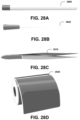
- FIG. 26 A shows for illustrative purposes only an example of a Sterile Blended Bag of one embodiment.
- FIG. 26 B shows for illustrative purposes only an example of a Buffer Solution of one embodiment.
- FIG. 27 A shows for illustrative purposes only an example of a YMR Activating Solution of one embodiment.
- FIG. 27 B shows for illustrative purposes only an example of a Buffer B Solution of one embodiment.
- FIG. 27 C shows for illustrative purposes only an example of a Pipette of one embodiment.
- FIG. 27 D shows for illustrative purposes only an example of a flower and plant material measuring scale of one embodiment.
- FIG. 28 A shows for illustrative purposes only an example of a Sterile Swab of one embodiment.
- FIG. 28 B shows for illustrative purposes only an example of a Sterile Swab out of case of one embodiment.
- FIG. 28 C shows for illustrative purposes only an example of a Forceps of one embodiment.
- FIG. 28 D shows for illustrative purposes only an example of Hazard Stickers of one embodiment.
- FIG. 29 A shows for illustrative purposes only an example of a Permanent Incubator Sticker of one embodiment.
- FIG. 29 B shows for illustrative purposes only an example of a Permanent Locator Sticker of one embodiment.
- FIG. 29 C shows for illustrative purposes only an example of a Target Locator Sticker of one embodiment.
- FIG. 30 A shows for illustrative purposes only an example of a scanner application in the learning center of one embodiment.
- FIG. 30 B shows for illustrative purposes only an example of a scanner application in the test sample reporting section of one embodiment.
- FIG. 30 C shows for illustrative purposes only an example of a scanner application in the user account portal section of one embodiment.
- FIG. 31 shows for illustrative purposes only an example of an air test process of one embodiment.
- FIG. 32 shows a block diagram of an overview of a flower test process of one embodiment.
- FIG. 33 shows a block diagram of an overview of a swab test process of one embodiment.
- the organic material processing method and devices can be configured using multiple styles of organic materials storage devices.
- the organic material processing method and devices can be configured to include petri dish culturing and can be configured to include mitigation of infected organic materials using the present invention.
- FIG. 1 shows for illustrative purposes only an example of an overview of an organic materials process flow of one embodiment.
- FIG. 1 shows an organic materials process flow 100 for processing organic materials for preservation and prevention of mold, bacteria infestations, rot, and decay and to reduce and prevent any degradation.
- the organic materials process flow 100 includes a process to collect data from a customer at sale 110 .
- the customer data is processed to send data to CRM, a customer relationship management system.
- the customer data is also processed to send data to the back office.
- the organic materials process flow 100 includes a customer portal 120 allowing a customer to order from the customer portal.
- a Customer Track and Trace 130 system in the process flow generates test results reports for the customer that include colony forming units (CFU) and other testing data.
- CFU colony forming units
- a process includes providing a storage facility, hardware, and equipment for storage and monitoring of the organic materials, storing organic materials in hardware and equipment configured for monitoring the condition of the organic materials during storage and gathering the condition of the organic materials during storage electronically using components of the hardware and equipment. Processing includes reporting electronically the condition of the organic materials to the facility and customer.
- the method includes providing a system for customers to reorder hardware and equipment automatically of one embodiment.
- the process allows the owner to pack and store their organic materials.
- the process allows an organic materials owner to measure the organic contents for mold, bacteria, rot, and decay for the owner packing and storing their organic materials. While being stored, the organic materials are monitored periodically to detect and mitigate any mold, bacteria, rot, and decay infestations. The owner of the organic materials may not have been aware of the mold and bacteria present in their organic materials. Periodic monitoring and testing provide early detection, providing the owner with a chance to mitigate the infestation and preserve at least a portion of the organic materials of one embodiment.
- FIG. 2 shows a block diagram of an overview of data collected from a customer of one embodiment.
- FIG. 2 shows sales 200 data collected from a customer at sale 210 .
- An owner packing and storing their organic materials is a normal operation. The owner of the organic materials may not be aware of mold and bacteria that are present in their organic materials.
- Periodic monitoring and testing provide early detection 220 .
- the testing includes multiple testing processes including The Air & Surface Test and The Flower Test.
- the stored organic materials are monitored periodically to detect and mitigate any mold, and bacteria infestations 230 .
- the process includes systems and treatments to eradicate the mold and bacteria 240 .
- the treatments mitigate the infestation and preserve at least a portion of the organic materials 250 . Processing organic materials for preservation and prevention of mold, bacteria infestations, rot, and decay and to reduce and prevent any degradation 260 of one embodiment.
- the sales data includes Customer Name, Company Name, Billing Address, Phone, and Shipping Address. Additionally, the data will include the customer's credit card (CC) information and their signature, and to agree to be charged every month, the customer verifies via agreement to Terms & Services at check out. The customer decides which Test Kit they would like to purchase; The Air & Surface Test, The Flower Test, or ala cart, depending on what they wish to order.
- CC credit card
- the data displays a Disclaimer and Terms of Service Agreement.
- a billing schedule is then set up by the anniversary of sign-up.
- the customer provides an email address for email-driven receipts, and the customer decides where invoices and receipts go.
- ALL information populates in a CRM, as well as the customer and client back office of one embodiment.
- FIG. 3 shows a block diagram of an overview of Part 1 showing a block diagram of a PO-created customer of one embodiment.
- FIG. 3 shows part 1 of an inventory system 300 for a purchase order (PO) created by a customer.
- the PO created by customer 310 orders a full Test Kit or orders supplies and tools ala cart as needed by the customer.
- the Test Kit includes at least an apron 1800 , YMR bio-insert rack-open 1900 , the air & surface test 2000 , mobile tool station 2300 , incubator front view 2400 , EZ photo stand 2500 , spray bottle 2510 , sterile blended bag 2600 , YMR activating solution 2610 , buffer solution(s) 2700 , buffer b 2710 , pipette 2720 , sterile swab 2800 , forceps 2810 , hazard stickers 2820 , permanent incubator sticker 2900 , permanent locator sticker 2920 , instructional manual, compartment custom cardboard package (Bio Inserts, FIGS. 19 - 23 ), shipping box, and soy liquid. Items include 100 dishes that hold organic materials cultures that the customer must refrigerate for one embodiment.
- the customer receives the first shipment, and depending on which system and test they bought, the customer receives 100 tests of The Air & Surface Test, and 20 tests of The Flower Test automatically. Additional items can be purchased through the customer portal, ala cart, which also connects to a shopping cart. Menu to be created for shopping cart based on item spreadsheet. All other expendables will be in Ala Cart that customers can order by a permanent QR code on the kit or through the customer portal.
- Part 2 a PO created vendor:
- FIG. 4 shows a block diagram of an overview of Part 2 showing a block diagram of an overview of a PO-created vendor of one embodiment.
- FIG. 4 shows a PO-created vendor 410 .
- Part 2 of an inventory system 400 is for a purchase order (PO) created vendor.
- PO purchase order
- no hardware will be kept on-site-Kits will be made to order.
- the software system will make a PO for each vendor when a kit is ordered. For example: Incubator from XYZ, QR code Scanner from ABC, etc.
- the system can generate the PO for each separate vendor and send it to the manager to send to the vendor.
- the manager will follow through with the vendor to make sure the item is ordered. Then the manager will know when the parts arrive, when they are put inside a kit, and when it is shipped by us and received by the customer. Once all other expendable inventory reaches a 30% volume, we re-order from our vendors. A notification to the manager occurs.
- a customer wants more hardware (i.e., incubator, QR scanner, etc.) they should be able to order from their customer portal, ala cart shopping cart, part of the menu of things to order. As the customer scans a dish at their facility, they get a notification in their back office, and we get a notification in our admin portal.
- Our admin Portal will have a summary page of all customer inventories in real-time as they are used-then link to the customer's personal page to maintain and monitor of one embodiment.
- a Customer Portal A Customer Portal:
- FIG. 5 shows for illustrative purposes only an example of a customer portal of one embodiment.
- FIG. 5 shows a customer portal 500 available to the customer for making orders and receiving reports and other communications.
- a customer logs in, they can create a username and password, and confirm their customer information. The customer is queried to name each permanent location QR code placement sticker (part of the test) in their account.
- a customer can review SOPs and Instructional Videos on how to operate the equipment and prepare organic materials cultures.
- the customer portal 500 also provides the customer with a review of their shopping cart with a menu of all expendables and hardware they may need to order. A Display Purchase history will inform the customer of their last orders.
- the customer portal 500 also provides access to tracking each dish (test) with date and time of movement, placement, pickup, incubator, photo, and disposal. This is the same information we receive, but specific to each customer.
- a personal inventory of expendables provides what the customer has used and what they need, as well as what their auto-ship arrangements are.
- the customer may also access the Final Reports-we provide a template for data to be filled in for each test with track and trace date, time, CFU, and identification data to come from our artificial intelligence (AI) system and devices.
- AI artificial intelligence
- the customer portal allows the customer to document cleaning or remediation actions taken after the report is given, i.e., clean affected areas, ozone dry room, etc. Access to remediation techniques they should use, and a summary page of all tests for their organic materials of one embodiment.
- FIG. 6 shows for illustrative purposes only, an example of manufacturing, packaging, and shipping of one embodiment.
- FIG. 6 shows the manufacturing, packaging, and shipping 600 processes including for manufacturing Real Time Inventory. Also, for manufacturing 610 , when something leaves or arrives, it is checked in and out and listed on a current inventory sheet of raw materials, hardware, and expendables, and raw materials must be included.
- a Cost of Goods is included with the cost of items for the customer, including shipping costs if applicable.
- a quality assurance (QA) checklist for managers to ensure all dishes are made properly and with a sign-off by the party preparing the dish.
- a QR code generator for dishes with printing is used to identify correctly the dish, source, date, and other information to track the dish culture.
- Packaging 620 processes include an Inventory of all Packing Materials (boxes, plastic sealer, filler, tape, labels, postage, etc.).
- a shipping label generator and label generator for logos are used to confirm the shipping location as provided by the customer and any company logos.
- Shipping 630 processes include notification when something goes out and when something comes in and will be checked in and out by the manager. The Manager will also receive a notification of when the customer receives all shipped items of one embodiment.
- FIG. 7 shows for illustrative purposes only an example of a customer trace and track of one embodiment.
- FIG. 7 shows a customer trace and track 700 processes and systems.
- a Customer receives the package and a notification as previously stated, is received.
- the notification triggers an email to the customer alerting that the package has been delivered with the Welcome Packet and Quick Start Guide attachment.
- the customer track and trace 700 processes and systems can generate template-based emails, as well as new custom emails to go to customers as needed.
- Customers can schedule a live Zoom demo of the products and procedures or an in-person demo.
- Customers can watch videos of items received, tutorial videos, and other educational videos.
- QR code scanner activation linking scanner to customer and portal—has a simple sample to ensure connectivity.
- the System asks for a QR code permanent placement information—cannot move forward without this activity being completed.
- a QR code reader is used to track placement, pickup, incubator, photo, disposal tracking time, date, and location, this is the same information we receive during activity, but specific to each customer in their customer portal account.
- After incubation, a picture is taken.
- the system analyzes the image and QR code in the picture.
- a Picture check is performed to ensure the quality of the image (blurry, out of frame, etc.).
- the picture is then sent to AI.
- AI reads the dish and sends the results (mold ID and CFU count back to a reporting system for display in the customer's back office with auto-fill on template with printing and PDF capabilities).
- the AI Assigns GREEN-YELLOW-RED designation based on CFU numbers ( FIG. 10 ) and provides those CFU numbers of one embodiment.
- the System places the picture on the report including the location of the sample and results.
- FIG. 8 shows a block diagram of an overview of information in a COA report of one embodiment.
- FIG. 8 shows a COA report 800 generated by the AI system and devices.
- the COA report provides the mold ID and CFU count of the tested plant materials.
- the AI reads the dish, sends results back after the incubation period (mold ID and CFU count back to reporting system for display in customer's back office with auto fill on the template with printing and PDF capabilities), and assigns GREEN-YELLOW-RED designation based on CFU numbers.
- the customer's name, number, and QR code of each dish and permanent placement name for example, VEG 1 , Tray 2 L.
- the AI report format includes the information described in FIG. 9 and shows the photo of the dish culture with any, if present, infestation of one embodiment.
- FIG. 9 shows a block diagram of an overview of an example of a certified report of one embodiment.
- FIG. 9 shows a certified report 900 .
- the certified report 900 also includes a date of report, a picture of dish 910 with QR code number 920 , permanent placement information, date and time of placement, incubation in and out time, photo, mold identification, and CFU count numbers-GREEN, YELLOW, RED. Suggested remediation accompanies the report.
- the report includes any additions to the document, as well as any notes before final printing.
- the AI system and devices allow the customer to add additional email addresses to receive reports (i.e., Director of Cultivation) of one embodiment.
- FIG. 10 shows for illustrative purposes only an example of a report of the CFU Scale of one embodiment.
- FIG. 10 shows an AI report format of a CFU Scale 1000 .
- the report includes a CFU (Colony Forming Units) Scale 1010 .
- the CFU Scale shows unit counts from 1 to 20+ 1020 . Acceptable unit counts receive an acceptable pass 1030 . Unacceptable unit counts receive various levels of action related to the plant materials.
- FIG. 11 shows for illustrative purposes only an example of a sample map of veg room 1 facility placement of veg room 1 permanent QR codes of one embodiment.
- FIG. 11 shows a sample map of the facility placement of veg room 1 permanent QR code 1100 .
- the veg room 1 facility placement of permanent QR codes 1110 provides uniformity in QR code 1110 placements, which allows the facility and customer to save time searching for the QR code 1110 and facilitates any photos needed to identify the equipment and contents of one embodiment.
- FIG. 12 shows for illustrative purposes only an example of a sample map of bloom room 1 facility placement of permanent QR codes of one embodiment.
- FIG. 12 shows a sample map of facility placement of bloom room 1 permanent locator QR codes 1200 .
- the predetermined placement of permanent locator QR codes 1210 provides uniformity in QR code 1210 placements which allows the facility and customer to save time searching for the QR code 1210 and facilitates any photos needed to identify the equipment and contents. In this instance, the three fans are needed to refresh the air for the maintenance of the conditions for the blooms of one embodiment.
- FIG. 13 shows for illustrative purposes only an example of a sample map of dry room 1 facility placement of permanent QR codes of one embodiment.
- FIG. 13 shows a sample map of the dry room 1 facility placement of dry room 1 permanent QR codes 1300 .
- the predetermined placement of permanent QR codes 1310 provides uniformity in QR code 1310 placements which allows the facility and customer to save time searching for the QR code 1310 and facilitates any photos needed to identify the equipment and contents. In this instance, the four tables need ease in identifying to prevent mismatching contents of the table during the drying processes of one embodiment.
- FIG. 14 shows for illustrative purposes only an example of AI beginning phase #1-train and integrate organisms of one embodiment.
- FIG. 14 shows a process for artificial intelligence (AI) system and devices phase #1 training 1401 to train the artificial intelligence device, the testing process, parameters, and results determinations.
- AI begins phase #1 trains and integrates organisms 1400 to acquire image recognition organism (cloud base) 1402 .
- Test mold recognition functionality of organism 1410 are examples of organisms.
- Determination of results is made with questions, for example, Did the organism detect all mold types? 1412 .
- a yes 1413 proceeds to test again with different variances & images of the same mold type 1414 .
- a no 1415 determination returns to create a photo bank of 20-25 species of mold 1404 and upload the bank of organisms to AI 1406 .
- the next training step includes, Did the organism detect all mold types? 1416 .
- a no 1415 determination returns to create a photo bank of 20-25 species of mold 1404 .
- a yes 1418 results in a process to acquire colony counting software 1420 within the AI device.
- the training continues to integrate colony counter software with image recognition organism 1422 to test the functionality of software speaking to each other and counting accuracy 1424 . Determination of results is made with questions, for example, Did organisms speak to each other? 1426 .
- a no 1425 results returns to the test functionality of software speaking to each other and counting accuracy 1424 .
- a yes 1427 result proceeds to upload mold and colony-specific already diagnosed photo 1430 .
- the process proceeds to run a picture test with mold colony counting specific images 1440 .
- the results query for example, Did the organism detect mold and counts correctly? 1450 .
- a no 1442 response returns to repeat the run picture test with mold colony count specific images 1440 .
- a yes 1452 response proceeds to upload mold type and colony count diagnosis to the petri dish QR code, also attach picture and diagnosis to petri QR code 1460 .
- the training process descriptions continue in FIG. 15 of one embodiment.
- FIG. 15 shows for illustrative purposes only an example of integrating fully functional AI organism of one embodiment.
- FIG. 15 shows a continuation from FIG. 14 of an example of an integrated fully functional AI organism.
- the process to integrate fully functional AI organisms is to create fully functional inventory tracking software to retrieve petri dish results and send to trace and track software to generate mold report 1500 .
- the process includes testing functionality and language conversation between AI organism and inventory tracking software 1502 .
- a determination of the results is made with the question, does AI provide accurate information to tracking software? 1504 .
- a no 1505 result returns the process to test functionality and language conversation between AI organism and inventory tracking software 1502 .
- a yes 1506 result continues the process of uploading microbial detection results and CFU (colony) count to trace and tracking software 1510 .
- a trace and track software will automate a mold report based on the AI petri dish results 1512 to test the functionality of the mold report generator based on mold diagnosis and colony count 1514 .
- the test results are reviewed with the question, “Did reports generate correctly with all current information?” 1520 .
- a no 1515 response returns the process to test the functionality of the mold report generator based on mold diagnosis and colony count 1514 .
- a yes 1521 response continues to upload reports to customer portal 1530 .
- the results are determined with the question, did the report get uploaded successfully to the correct customer portal? 1540 .
- a no 1532 answer returns the process to upload reports to customer portal 1530 .
- a yes 1542 answer continues to generate a mold report for each petri 1550 dish tested to finish phase #1 1560 of the AI training of one embodiment.
- FIG. 16 shows for illustrative purposes only an example of an acquired customer of one embodiment.
- FIG. 16 shows the steps to 1 . acquire a customer 1600 .
- Step 2 Money is cashiered, an account & password are created for a training center and customer back office, a shipping manifest is created, AI account is provisioned 1602 .
- the customer then follows step 2 a .
- customer creates a back-office username and password, the back office will contain: customer information, customer assigned ID #, order history, shopping cart, and the learning center uploaded pictures for AI reports delivered 1603 .
- the acquisition continues with step 3 .
- warehouse pulls items from inventory>fulfills order>ships out order>package tracking all products are scanned for QR code assigned to individual customers and sent to inventory control system 1604 .
- Step 4 The customer receives the kit, EZML is notified, an onboard welcome email is sent with the customer schedule, and directions to the learning center to watch the online videos short courses 1610 .
- step 5 find a location in a facility with power for EZ micro lab system(s) 1612 and as directed in step 6 .
- assign permanent QR code locations fill out the map and place in facility 1614 .
- the instructions include customer action in step 7 . open the QR code reader and watch video(s) for setup 1616 .
- Step 8 fill in customer scheduling using scheduling program 1620 .
- the instructions continue with 9 . day 1 place the first round of dishes on 5 of 10 permanent markers in each room scanning each one upon placement-scanning the dish and location 1622 . 10 . day 1 (cont'd) collect placed dishes after 3 hours 1624 . 11 .
- day 1 place collected dishes in the incubator-scanning again so the system knows the dishes are in the incubator and let sit for the allotted time 1630 .
- the schedule continues with 12 . collection day collect dishes from the incubator scan dish and photograph 1640 . Continuing 13 . collection day upload photographs to the back office then the file is uploaded to AI for analysis 1650 . Continuing 14 . collection day place used dishes in the same hazard bag they came in scanning again using alcohol to clean the photo stand, incubator, and area 1660 .
- the scheduling descriptions continue in FIG. 17 of one embodiment.
- FIG. 17 shows for illustrative purposes only an example of a received report from AI reader of one embodiment.
- FIG. 17 shows a continuation from FIG. 16 .
- Step 14 continues with 14 . day after upload receive report from AI reader 1700 . 14 a . If there is a problem with one of your photographs, you will be asked to retake the picture and re-upload it to system 1710 . 14 B. if no problem, discard used dishes once the report is received 1720 . 15 . Day 7 if no problems exist repeat steps 8 - 10 with a new set of dishes on 5 other permanent markers in each room not used yet and repeat in all rooms 1730 .
- 16 a day 12 repeat steps 8 - 13 with the above-placed dishes 1740 . 16 b . day 7 if problems do exist and if mold is found initiate mitigation and repeat steps 8 - 10 1750 . 16 c . If the Fusarium is found go back to your kit and pull the Fusarium test, follow the instructions for the Fusarium test to confirm contamination 1760 . 16 d . if Fusarium, Aspergillus, Salmonella, E. coli, Lister, S Arueu, Mucor, P. Aeruginosa is detected 1780 ; retest, sanitation, destruction, or mitigation begins 1781 .
- the species identified include Fusarium, Aspergillus, Salmonella, E. coli, Lister, S Arueu, Mucor, P. Aeruginosa 1783 . 16 c . If Fusarium is found go back to your kit and pull the Fusarium test, follow the instructions for the Fusarium test to confirm contamination 1760 .
- Retest area following steps 8 - 10 incubation time will vary based on species 1784 . Repeat steps 11 - 13 1785 and repeat weekly 1790 . Continue mitigation and isolation of affected area 1786 of one embodiment.
- FIG. 18 shows for illustrative purposes only an example of a utility apron of one embodiment.
- FIG. 18 shows a utility apron 1800 that is included in the Kit.
- the utility apron 1800 includes a scanner pocket 1810 , swab pocket 1820 , spray bottle pocket 1830 , and rack pocket(s) 1840 to allow the user to carry the tools to carry out the testing processes of one embodiment.
- FIG. 19 A shows for illustrative purposes only an example of a YMR bio-insert rack open of one embodiment.
- FIG. 19 A shows YMR bio-insert rack-open 1900 . Through the opening are seen racks 1910 used in the test processing.
- Yeast/Mold Rapid (YMR) is a test method to detect mold and yeast of one embodiment.
- FIG. 19 B shows for illustrative purposes only an example of a YMR bio-insert rack bottom of one embodiment.
- FIG. 19 B shows a YMR bio-insert rack-bottom 1920 that includes an identifying barcode 1930 of one embodiment.
- FIG. 20 shows for illustrative purposes only an example of an air and surface test of one embodiment.
- FIG. 20 shows the air & surface test 2000 in a container marked with an independent concurrent QR code 2010 .
- the air & surface test 2000 in a container shows a notation area 2020 , a drawer with activation solution 2030 , a plating area 2040 , and a window cutout to display the type of test plate 2050 of one embodiment.
- FIG. 21 A shows for illustrative purposes only an example of an air and surface test front view open of one embodiment.
- FIG. 21 A shows an open test kit 2130 revealing the plant material drawer 2150 of one embodiment.
- FIG. 21 B shows for illustrative purposes only an example of an air and surface test front view closed of one embodiment.
- FIG. 21 B shows the air & surface test top 2100 that includes a plating area 2040 of one embodiment.
- FIG. 21 C shows for illustrative purposes only an example of an air and surface test back-bottom view of one embodiment.
- FIG. 21 C shows the air & surface test bottom 2110 which includes a QR code 2120 for identification of one embodiment.
- FIG. 22 shows for illustrative purposes only an example of a Flower Test Bio-Insert-Open of one embodiment.
- FIG. 22 shows the flower test 2200 independent concurrent QR code 2010 used to identify the particular test of one embodiment.
- FIG. 23 A shows for illustrative purposes only an example of a Mobile Tool Station of one embodiment.
- FIG. 23 A shows a mobile tool station 2300 used to carry the tools the user uses during the testing processes of one embodiment.
- FIG. 23 B shows for illustrative purposes only an example of a Mobile Tool Station Opened of one embodiment.
- FIG. 23 B shows a mobile tool station opened 2302 showing the tools the user uses during the testing processes of one embodiment.
- FIG. 23 C shows for illustrative purposes only an example of a Mobile Carrying Case of one embodiment.
- FIG. 23 C shows a mobile carrying case 2310 that allows the user to carry tools and supplies from, for example, one room to another room for testing of one embodiment.
- FIG. 23 D shows for illustrative purposes only an example of a Mobile Carrying Case Opened of one embodiment.
- FIG. 23 C shows a mobile carrying case opened 2312 showing the user tools and supplies available to the user from, for example, one room to another room for testing of one embodiment.
- FIG. 24 A shows for illustrative purposes only an example of an Incubator front perspective view of one embodiment.
- FIG. 24 A shows incubator front view 2400 .
- the front door includes a glass window allowing the user to check the testing materials without having to open the door and interrupt the incubation process of one embodiment.
- FIG. 24 B shows for illustrative purposes only an example of an Incubator back view of one embodiment.
- FIG. 24 B shows incubator back view 2410 showing the exhaust ventilation screen and the heater elements of one embodiment.
- FIG. 25 A shows for illustrative purposes only an example of a photo stand of one embodiment.
- FIG. 25 A shows an EZ photo stand 2500 used to mount a camera to photograph plant materials used in the processing to detect the presence of mold.
- the photograph is sent to an artificial intelligence (AI) device.
- the AI device reads the dish and sends the results (mold ID and CFU count back to the reporting system for display of one embodiment.
- FIG. 25 B shows for illustrative purposes only an example of an Isopropyl Spray Bottle of one embodiment.
- FIG. 25 B shows an isopropyl spray bottle 2510 used to apply alcohol for cleansing tools of any mold acquired during contact with the plant materials of one embodiment.
- FIG. 26 A shows for illustrative purposes only an example of a Sterile Blended Bag of one embodiment.
- FIG. 26 A shows a sterile blended bag 2600 used to store plant materials during the testing processes of one embodiment.
- FIG. 26 B shows for illustrative purposes only an example of a YMR Activating Solution of one embodiment.
- FIG. 26 B shows YMR activating solution 2610 used to apply to plant materials to detect mold of one embodiment
- FIG. 27 A shows for illustrative purposes only an example of a buffer solution(s) of one embodiment.
- FIG. 27 A shows a buffer solution(s) 2700 used in the testing process of one embodiment.
- FIG. 27 B shows for illustrative purposes only an example of a Buffer B Solution of one embodiment.
- FIG. 27 B shows Buffer B 2710 used in the testing process of one embodiment.
- FIG. 27 C shows for illustrative purposes only an example of a Pipette of one embodiment.
- FIG. 27 C shows a pipette 2720 , where pipettes are used for water collecting during the testing processing of one embodiment.
- FIG. 27 D shows for illustrative purposes only an example of a flower and plant material measuring scale of one embodiment.
- FIG. 27 D shows a flower and plant material measuring scale 2730 used to measure a predetermined weight of flower and plant material to prepare for testing of one embodiment.
- FIG. 28 A shows for illustrative purposes only an example of a Sterile Swab of one embodiment.
- FIG. 28 A shows a sterile swab 2800 . Multiple sterile swabs are provided with the testing equipment of one embodiment.
- FIG. 28 B shows for illustrative purposes only an example of a Sterile Swab out of case of one embodiment.
- FIG. 28 B shows a sterile swab 2802 Sterile Swab out of the case.
- the sterile swabs are used to take test samples of surfaces, for example, shelves, tables, and other surfaces within the facility to detect mold and bacteria infestations. Multiple sterile swabs are provided with the testing equipment of one embodiment.
- FIG. 28 C shows for illustrative purposes only an example of a Forceps of one embodiment.
- FIG. 28 C shows forceps 2810 used to handle plant materials to prevent physical contact with the user.
- the forceps 2810 in one embodiment are used to select and place flower and plant materials on the measuring scale 2730 during the Flower Test.
- the forceps 2810 are cleaned using alcohol between uses to prevent conveying mold from infected plant materials to non-infected plant materials of one embodiment.
- FIG. 28 D shows for illustrative purposes only an example of Hazard Stickers of one embodiment.
- FIG. 28 D shows hazard stickers 2820 used to seal used test sample.
- the hazard stickers 2820 identify and alert users of the content of a container with possible infected plant materials of one embodiment.
- FIG. 29 A shows for illustrative purposes only an example of a Permanent Incubator Sticker of one embodiment.
- FIG. 29 A shows a permanent incubator sticker 2900 used to identify with a QR code A 2910 plant material containers carrying incubated plant materials of one embodiment.
- FIG. 29 B shows for illustrative purpose only an example of a Permanent Locator Sticker of one embodiment.
- FIG. 29 B shows a permanent locator sticker 2920 identified with a QR code 1 2930 .
- the permanent locator sticker 2920 is used to locate and identify specific groupings of plant materials of one embodiment.
- FIG. 29 C shows for illustrative purpose only an example of a Target Locator Sticker of one embodiment.
- FIG. 29 C shows a Target Locator Sticker 2940 used to locate air testing sites within the facility.
- a bio-insert is prepared for testing and placed on the Target Locator Sticker 2940 for 2 hours to get exposure to airflow, then prepared for scanning and a network determination of any mold and bacteria infestations of one embodiment.
- FIG. 30 A shows for illustrative purpose only an example of a scanner application in the learning center of one embodiment.
- FIG. 30 A shows a scanner 3000 having a plant material testing application.
- the user has selected the learning center 3002 to view instructions for a particular testing action of one embodiment.
- FIG. 30 B shows for illustrative purposes only an example of a scanner application in the test sample reporting section of one embodiment.
- FIG. 30 B shows a scanner 3000 having a plant material testing application.
- the user has selected the test sample reporting section 3012 to view a unit count 3014 of a test sample of any detected mold and bacteria infestations of one embodiment.
- FIG. 30 C shows for illustrative purpose only an example of a scanner application in the user account portal section of one embodiment.
- FIG. 30 C shows a scanner 3000 having a plant material testing application.
- the user has selected the user account portal section 3022 to view the user's account, for example, to order additional testing supplies of one embodiment.
- FIG. 31 shows for illustrative purpose only an example of an air test process of one embodiment.
- FIG. 31 shows to begin an air sample testing 3100 , the user will put on gloves and the apron, making sure to spray the gloves with 70% isopropyl, rubbing hands together till dry. Take a Bio-Insert out of the rack, remove the lid, and place it on the Bio-Insert for later use. Remove the activating solution from the Bio-Insert, pouring the entire solution evenly onto the plate 3102 . Place the empty container back in the box.
- the user presses the capture button to capture a photo of the bio-insert plated test area.
- the scanner automatically transmits the sample photo to the network to determine any microorganisms 3130 .
- the transmitted photo is received by the network to determine and create an individual micro report using artificial intelligence 3140 .
- the network sends a certificate of analysis (COA) for each sample to the user 3150 of one embodiment.
- COA certificate of analysis
- FIG. 32 shows a block diagram of an overview of a flower test process of one embodiment.
- FIG. 32 shows the flower test process that will begin the flower test by taking a sterilized bag from the chosen bio-insert 3200 .
- the user will use the forceps to place and weigh one gram of plant flower or plant material to be tested on the scale, then place the plant flower or plant material into a sterilized bag with the forceps 3210 .
- the process continues with a user pouring the entire buffer solution “B” into the bag with the plant flower or plant material, then sealing the bag and shaking and crumbling the test sample for 60 seconds until homogenized 3220 .
- the user will obtain a 1 ml liquid sample from the bag with a pipette 3230 , then proceed to squeeze the solution sample onto the bio-insert plate, covering the entire surface area 3240 .
- the user will scan the bio-insert QR code; the app will prompt the user to name the sample material and scan the permanent locator marker from the location where the sample was taken 3250 .
- the next step is to place all inside with incubator all bio-inserts and scan the permanent incubator QR code with the incubator set at 25 degrees Celsius, and return in 72 hours 3260 .
- the user After incubation, the user proceeds to remove flower tests previously placed in the incubator individually scan the bio-inserts, and repeat for all test samples 3270 . After scanning each test sample, the user will remove the bio-inserts from the photo stand and place them back into the rack, seal the rack with a red hazard sticker, and dispose of material with user predetermined internal compliance standard operating procedures 3280 .
- the scanner automatically transmits sample photos to the network to determine any microorganisms present and create individual micro reports using artificial intelligence 3290 . In 24 hours, the network sends a certificate of analysis (COA) for each sample to the user 3292 of one embodiment.
- COA certificate of analysis
- FIG. 33 shows a block diagram of an overview of a swab test process of one embodiment.
- FIG. 33 shows a swab test process that will begin the surface test by pouring activating buffer on the bio-insert circle test area plate 3300 .
- the user will extract the swab from the swab cartridge, and roll the tip over the surface for at least 10 seconds 3310 .
- the user will roll over the activating buffer on the plate and replace the place lid on top of the bio insert plate (circle), ready for incubation 3320 . Collect the surface test samples and place multiple racks of the bio inserts into the incubator 3330 .
- the user will incubate test samples at 25 degrees Celsius for 72 hours, the incubator timer alerts the user when the incubation period is complete 3340 .
- the user proceeds to scan the bio-insert QR code; the app will prompt the user to name the sample material and scan the permanent locator marker from the location where the sample was taken 3350 .
- the user will place the scanner on the top level of the photo stand to photograph the bio-insert surface plate placed on the bottom level and remove the lid, and digitally upload the test samples individually 3360 .
- the user After photographing each test sample, the user will remove the bio-inserts from the photo stand and place them back into the rack, seal the rack with a red hazard sticker, and dispose of material with user predetermined internal compliance standard operating procedures 3370 .
- the scanner automatically transmits sample photos to the network to determine and create individual micro reports using artificial intelligence 3380 . In 24 hours, the network sends a certificate of analysis (COA) for each sample to the user 3390 of one embodiment.
- COA certificate of analysis
- a website application is provided in addition to mobile application for computer access to the learning center, reporting of testing information and photograph, receiving coa reports, and ordering kits and supplies. The user gains access using the same account information and logins that are used for the mobile application.
- artificial intelligence algorithms to determine image processing detection of colony counts by automated machine learning models, self-learning and evolving over more data accumulation.
- the artificial intelligence device machine learning application is taught using analysis with mathematical models of data to identify patterns of known harmful microorganisms stored on at least one database coupled to the server and uses comparisons of those patterns with organic materials test samples detected mold and bacteria patterns to identify the detected harmful microorganisms.
- the machine learning accumulation of data is used in the AI algorithms to assist the user in preparing reports on the cultivation and other aspects of the growth and productivity of the cultivation.
- an X, Y coordinate tracking with Cartesian Coordinates (inside facility) and GPS tagging. This will produce many other proactive early detection problem analysis and identification to prevent spreading of any bacterial conditions and infestations.
- the Cartesian Coordinates with gps tagging will be overlaid on the individual rooms mapped in the facility and identified using the QR code locator markers.
- Schedule notifications by location over service events, timers to help users find overlooked or required maintenance by location will assist the user in maintaining a regular schedule of maintenance to prevent bacterial growth and infestations.
- Schedule notifications are sent through messaging as reminders of the tasks to perform.
- the AI system is scheduled to produce trending current testing results vs historic comparisons periodically to gage progress in controlling bacterial detection.
- Dashboard level NetworkOperation Kiosk/Screens are placed at critical locations.
- the dashboard kiosks will monitor multiple facilities.
- the displayed information will include high level aggregate summaries, drill down to hierarchy level related sub-location/zones.
- the visualizations at critical locations being easily seen by employees and users will keep them abreast of progress being made and remind them of the vigilance in testing and disinfection of all surfaces and equipment to maintain a bacterial free environment leading to increased productivity.
- the facility is fitted with various types of sensors to detect bacterial presence.
- the type of sensor may be different at different locations within the facility.
- the different types of sensors includes autofluorescence Imaging, fluorescence sensor integrate into goggles, Light-emitting diodes (LEDs) causing illuminated samples to fluoresce without destroying them, Paper-based sensors for bacteria detection, culture-based assays, polymerase chain reaction detection, UV Flashlight Black Light detectors, detecting bacteria using fluorescence-based dyes, optical, mechanical, or electrical biosensors, surface plasmon resonance (SPR) biosensors, mechanical biosensors based on quartz crystal microbalance (QCM) or cantilever technology without the need for sample processing or extra reagents, Electrochemical biosensors comprising potentiometric, amperometric, and impedimetric sensing techniques, and many others using lasers and other optical detection techniques.
- SPR surface plasmon resonance
- QCM quartz crystal microbalance
- Bacterial treatments of numerous embodiments are used to eradicate bacterial infestations.
- the treatments include applying preventive sprays of copper-based bactericides to infestations will kill bacteria.
- the kit includes isopropyl alcohol in a spray bottle to disinfect surfaces and equipment.
- Organic fungicides and bactericides that do not damage healthy plant materials is used to control bacteria infestations without damaging the health balance of the plant.
- Ozonated water in the form of droplets and mist is applied to the entire plant to eradicate bacteria without damage the healthy section of the plant.
- the scanner application in one embodiment, includes bacterial detection software and sensor detection.
- Optical detection technologies integrated into the scanner device can detect bacteria and the corresponding analyzer and signal transmission system display the type of bacteria and other data detected.
- the scanner device camera is used to photograph the detected bacteria.
Landscapes
- Physics & Mathematics (AREA)
- Health & Medical Sciences (AREA)
- Chemical & Material Sciences (AREA)
- Life Sciences & Earth Sciences (AREA)
- General Health & Medical Sciences (AREA)
- Analytical Chemistry (AREA)
- Biochemistry (AREA)
- Immunology (AREA)
- General Physics & Mathematics (AREA)
- Spectroscopy & Molecular Physics (AREA)
- Pathology (AREA)
- Organic Chemistry (AREA)
- Engineering & Computer Science (AREA)
- Proteomics, Peptides & Aminoacids (AREA)
- Nuclear Medicine, Radiotherapy & Molecular Imaging (AREA)
- Wood Science & Technology (AREA)
- Zoology (AREA)
- Molecular Biology (AREA)
- General Engineering & Computer Science (AREA)
- Bioinformatics & Cheminformatics (AREA)
- Genetics & Genomics (AREA)
- Microbiology (AREA)
- Biotechnology (AREA)
- Biophysics (AREA)
- Toxicology (AREA)
- Apparatus Associated With Microorganisms And Enzymes (AREA)
Abstract
The embodiments disclose a portable microbial test kit including a plurality of organic materials configured to be processed for preservation and prevention of mold, bacteria infestations, rot, and decay and reduce and prevent any degradation, a storage facility, a plurality of hardware, and a plurality of equipment configured for storage and monitoring of the plurality of organic materials, wherein the hardware and the equipment are configured to monitor the condition of the organic materials during storage, a plurality of components coupled to the hardware and the equipment configured to electronically monitor the condition of the organic materials during storage, at least one electronic device coupled to the plurality of hardware and the plurality of equipment configured to report electronically the condition of the organic materials to the facility and customer, and a system coupled to the at least one electronic device configured for customers to automatically reorder hardware and equipment.
Description
Processing of organic materials for preservation until use is plagued with problems of degradation of the organic materials. Mold, bacteria infestations, rot, and decay can change the quality and valuable characteristics of organic materials. The degradation can cause a complete loss of the crop and at least a decline in the commercial value of the organic materials crop marketability and market value. Critical processing steps and planning can reduce and even prevent any degradation from taking place.
In the following description, reference is made to the accompanying drawings, which form a part hereof, and which are shown by way of illustration a specific example in which the invention may be practiced. It is to be understood that other embodiments may be utilized and structural changes may be made without departing from the scope of the present invention.
General Overview:
It should be noted that the descriptions that follow, for example, in terms of an organic material processing method and devices are described for illustrative purposes and the underlying system can apply to any number and multiple types of organic materials. In one embodiment of the present invention, the organic material processing method and devices can be configured using multiple styles of organic materials storage devices. The organic material processing method and devices can be configured to include petri dish culturing and can be configured to include mitigation of infected organic materials using the present invention.
The customer data is also processed to send data to the back office. The organic materials process flow 100 includes a customer portal 120 allowing a customer to order from the customer portal. A Customer Track and Trace 130 system in the process flow generates test results reports for the customer that include colony forming units (CFU) and other testing data.
A process includes providing a storage facility, hardware, and equipment for storage and monitoring of the organic materials, storing organic materials in hardware and equipment configured for monitoring the condition of the organic materials during storage and gathering the condition of the organic materials during storage electronically using components of the hardware and equipment. Processing includes reporting electronically the condition of the organic materials to the facility and customer.
The method includes providing a system for customers to reorder hardware and equipment automatically of one embodiment. The process allows the owner to pack and store their organic materials.
The process allows an organic materials owner to measure the organic contents for mold, bacteria, rot, and decay for the owner packing and storing their organic materials. While being stored, the organic materials are monitored periodically to detect and mitigate any mold, bacteria, rot, and decay infestations. The owner of the organic materials may not have been aware of the mold and bacteria present in their organic materials. Periodic monitoring and testing provide early detection, providing the owner with a chance to mitigate the infestation and preserve at least a portion of the organic materials of one embodiment.
The sales data includes Customer Name, Company Name, Billing Address, Phone, and Shipping Address. Additionally, the data will include the customer's credit card (CC) information and their signature, and to agree to be charged every month, the customer verifies via agreement to Terms & Services at check out. The customer decides which Test Kit they would like to purchase; The Air & Surface Test, The Flower Test, or ala cart, depending on what they wish to order.
The data displays a Disclaimer and Terms of Service Agreement. A billing schedule is then set up by the anniversary of sign-up. The customer provides an email address for email-driven receipts, and the customer decides where invoices and receipts go. ALL information populates in a CRM, as well as the customer and client back office of one embodiment.
A PO Created Customer:
The Test Kit includes at least an apron 1800, YMR bio-insert rack-open 1900, the air & surface test 2000, mobile tool station 2300, incubator front view 2400, EZ photo stand 2500, spray bottle 2510, sterile blended bag 2600, YMR activating solution 2610, buffer solution(s) 2700, buffer b 2710, pipette 2720, sterile swab 2800, forceps 2810, hazard stickers 2820, permanent incubator sticker 2900, permanent locator sticker 2920, instructional manual, compartment custom cardboard package (Bio Inserts, FIGS. 19-23 ), shipping box, and soy liquid. Items include 100 dishes that hold organic materials cultures that the customer must refrigerate for one embodiment.
Every month based on the sign-up date, the customer receives the first shipment, and depending on which system and test they bought, the customer receives 100 tests of The Air & Surface Test, and 20 tests of The Flower Test automatically. Additional items can be purchased through the customer portal, ala cart, which also connects to a shopping cart. Menu to be created for shopping cart based on item spreadsheet. All other expendables will be in Ala Cart that customers can order by a permanent QR code on the kit or through the customer portal.
For example: if the customer needs more gloves; they take their QR code reader and swipe the gloves' QR code on the kit box and it automatically opens the shopping cart and places the order. The scanned order will go to the customer portal that connects to the shopping cart. Same for all expendables except petri dishes—100 will be sent every month based on their sign-up date of one embodiment.
Part 2 a PO created vendor:
The system can generate the PO for each separate vendor and send it to the manager to send to the vendor. The manager will follow through with the vendor to make sure the item is ordered. Then the manager will know when the parts arrive, when they are put inside a kit, and when it is shipped by us and received by the customer. Once all other expendable inventory reaches a 30% volume, we re-order from our vendors. A notification to the manager occurs.
If a customer wants more hardware (i.e., incubator, QR scanner, etc.) they should be able to order from their customer portal, ala cart shopping cart, part of the menu of things to order. As the customer scans a dish at their facility, they get a notification in their back office, and we get a notification in our admin portal. Our admin Portal will have a summary page of all customer inventories in real-time as they are used-then link to the customer's personal page to maintain and monitor of one embodiment.
A Customer Portal:
The customer portal 500 also provides the customer with a review of their shopping cart with a menu of all expendables and hardware they may need to order. A Display Purchase history will inform the customer of their last orders. The customer portal 500 also provides access to tracking each dish (test) with date and time of movement, placement, pickup, incubator, photo, and disposal. This is the same information we receive, but specific to each customer.
A personal inventory of expendables provides what the customer has used and what they need, as well as what their auto-ship arrangements are. The customer may also access the Final Reports-we provide a template for data to be filled in for each test with track and trace date, time, CFU, and identification data to come from our artificial intelligence (AI) system and devices. The customer portal allows the customer to document cleaning or remediation actions taken after the report is given, i.e., clean affected areas, ozone dry room, etc. Access to remediation techniques they should use, and a summary page of all tests for their organic materials of one embodiment.
Manufacturing, Packaging, and Shipping:
A Cost of Goods (COG) is included with the cost of items for the customer, including shipping costs if applicable. A quality assurance (QA) checklist for managers to ensure all dishes are made properly and with a sign-off by the party preparing the dish. A QR code generator for dishes with printing is used to identify correctly the dish, source, date, and other information to track the dish culture.
Packaging 620 processes include an Inventory of all Packing Materials (boxes, plastic sealer, filler, tape, labels, postage, etc.). A shipping label generator and label generator for logos are used to confirm the shipping location as provided by the customer and any company logos. Shipping 630 processes include notification when something goes out and when something comes in and will be checked in and out by the manager. The Manager will also receive a notification of when the customer receives all shipped items of one embodiment.
Customer Trace and Track:
The System asks for a QR code permanent placement information—cannot move forward without this activity being completed. A QR code reader is used to track placement, pickup, incubator, photo, disposal tracking time, date, and location, this is the same information we receive during activity, but specific to each customer in their customer portal account. After incubation, a picture is taken. The system analyzes the image and QR code in the picture. A Picture check is performed to ensure the quality of the image (blurry, out of frame, etc.).
The picture is then sent to AI. AI reads the dish and sends the results (mold ID and CFU count back to a reporting system for display in the customer's back office with auto-fill on template with printing and PDF capabilities). The AI Assigns GREEN-YELLOW-RED designation based on CFU numbers (FIG. 10 ) and provides those CFU numbers of one embodiment. The System places the picture on the report including the location of the sample and results.
A COA Report:
A Certified Report:
A Report on the CFU Scale:
A sample map of the placement of veg Room 1 Permanent QR Codes:
A Sample Map of Bloom Room 1 Facility Placement of Permanent Locator QR Codes:
A Sample Map of Dry Room 1 Facility Permanent Locator QR Codes:
AI Begin Phase #1:
Determination of results is made with questions, for example, Did the organism detect all mold types? 1412. A yes 1413 proceeds to test again with different variances & images of the same mold type 1414. A no 1415 determination returns to create a photo bank of 20-25 species of mold 1404 and upload the bank of organisms to AI 1406. The next training step includes, Did the organism detect all mold types? 1416. A no 1415 determination returns to create a photo bank of 20-25 species of mold 1404.
A yes 1418 results in a process to acquire colony counting software 1420 within the AI device. The training continues to integrate colony counter software with image recognition organism 1422 to test the functionality of software speaking to each other and counting accuracy 1424. Determination of results is made with questions, for example, Did organisms speak to each other? 1426. A no 1425 results returns to the test functionality of software speaking to each other and counting accuracy 1424. A yes 1427 result proceeds to upload mold and colony-specific already diagnosed photo 1430.
The process proceeds to run a picture test with mold colony counting specific images 1440. The results query, for example, Did the organism detect mold and counts correctly? 1450. A no 1442 response returns to repeat the run picture test with mold colony count specific images 1440. A yes 1452 response proceeds to upload mold type and colony count diagnosis to the petri dish QR code, also attach picture and diagnosis to petri QR code 1460. The training process descriptions continue in FIG. 15 of one embodiment.
Integrate Fully Functional AI Organism:
A determination of the results is made with the question, does AI provide accurate information to tracking software? 1504. A no 1505 result returns the process to test functionality and language conversation between AI organism and inventory tracking software 1502. A yes 1506 result continues the process of uploading microbial detection results and CFU (colony) count to trace and tracking software 1510. A trace and track software will automate a mold report based on the AI petri dish results 1512 to test the functionality of the mold report generator based on mold diagnosis and colony count 1514. The test results are reviewed with the question, “Did reports generate correctly with all current information?” 1520. A no 1515 response returns the process to test the functionality of the mold report generator based on mold diagnosis and colony count 1514.
A yes 1521 response continues to upload reports to customer portal 1530. The results are determined with the question, did the report get uploaded successfully to the correct customer portal? 1540. A no 1532 answer returns the process to upload reports to customer portal 1530. A yes 1542 answer continues to generate a mold report for each petri 1550 dish tested to finish phase # 1 1560 of the AI training of one embodiment.
Acquire Customer:
The customer then will follow step 5. find a location in a facility with power for EZ micro lab system(s) 1612 and as directed in step 6. assign permanent QR code locations fill out the map and place in facility 1614. The instructions include customer action in step 7. open the QR code reader and watch video(s) for setup 1616. Step 8. fill in customer scheduling using scheduling program 1620. The instructions continue with 9. day 1 place the first round of dishes on 5 of 10 permanent markers in each room scanning each one upon placement-scanning the dish and location 1622. 10. day 1 (cont'd) collect placed dishes after 3 hours 1624. 11. day 1 (cont'd) place collected dishes in the incubator-scanning again so the system knows the dishes are in the incubator and let sit for the allotted time 1630. The schedule continues with 12. collection day collect dishes from the incubator scan dish and photograph 1640. Continuing 13. collection day upload photographs to the back office then the file is uploaded to AI for analysis 1650. Continuing 14. collection day place used dishes in the same hazard bag they came in scanning again using alcohol to clean the photo stand, incubator, and area 1660. The scheduling descriptions continue in FIG. 17 of one embodiment.
Receive Report from AI Reader:
16 a. day 12 repeat steps 8-13 with the above-placed dishes 1740. 16 b. day 7 if problems do exist and if mold is found initiate mitigation and repeat steps 8-10 1750. 16 c. If the Fusarium is found go back to your kit and pull the Fusarium test, follow the instructions for the Fusarium test to confirm contamination 1760. 16 d. if Fusarium, Aspergillus, Salmonella, E. coli, Lister, S Arueu, Mucor, P. Aeruginosa is detected 1780; retest, sanitation, destruction, or mitigation begins 1781.
Retest with specific plates based on what species was identified 1782. The species identified include Fusarium, Aspergillus, Salmonella, E. coli, Lister, S Arueu, Mucor, P. Aeruginosa 1783. 16 c. If Fusarium is found go back to your kit and pull the Fusarium test, follow the instructions for the Fusarium test to confirm contamination 1760. Retest area following steps 8-10, incubation time will vary based on species 1784. Repeat steps 11-13 1785 and repeat weekly 1790. Continue mitigation and isolation of affected area 1786 of one embodiment.
Utility Apron:
YMR Bio-Insert Rack Open:
YMR Bio-Insert Rack Bottom:
Air and Surface Test:
Air and Surface Test Front View Open:
Air and Surface Test Front View Closed:
Air and Surface Test Back-Bottom View:
Flower Test Bio-Insert-Open:
Mobile Tool Station:
Mobile Tool Station Opened:
Mobile Carrying Case:
Mobile Carrying Case Opened:
Incubator Front Perspective View:
Incubator Back View:
Photo Stand:
Isopropyl Spray Bottle:
Sterile Blended Bag:
YMR Activating Solution:
Buffer Solution(s):
Buffer B Solution:
Pipette:
Flower and Plant Material Measuring Scale:
Sterile Swab:
Sterile Swab Out of Case:
Forceps:
Hazard Stickers:
Permanent Incubator Sticker:
Permanent Locator Sticker:
Target Locator Sticker:
A Scanner Application in the Learning Center:
Scanner Application in the Test Sample Reporting Section:
A Scanner Application in the User Account Portal Section:
An Air Test Process:
The user then places the bio-insert on the sample target location 3110. Let the Bio-insert sit for 2 Hours before collecting 3112. After placing the bio-insert on the target location the user will scan the bio-insert QR code and then scan a permanent location marker closest to the test target location to link a location. The user will scan the bio-insert after 2 hours 3120. The user will place the scanner on the top level of the photo stand scanner support and the bio-insert being tested on the bottom level 3122 to standardize the focal length and image size for analysis.
The user presses the capture button to capture a photo of the bio-insert plated test area. The scanner automatically transmits the sample photo to the network to determine any microorganisms 3130. The transmitted photo is received by the network to determine and create an individual micro report using artificial intelligence 3140. In 24 hours, the network sends a certificate of analysis (COA) for each sample to the user 3150 of one embodiment.
A Flower Test Process:
The user will obtain a 1 ml liquid sample from the bag with a pipette 3230, then proceed to squeeze the solution sample onto the bio-insert plate, covering the entire surface area 3240. The user will scan the bio-insert QR code; the app will prompt the user to name the sample material and scan the permanent locator marker from the location where the sample was taken 3250. The next step is to place all inside with incubator all bio-inserts and scan the permanent incubator QR code with the incubator set at 25 degrees Celsius, and return in 72 hours 3260.
After incubation, the user proceeds to remove flower tests previously placed in the incubator individually scan the bio-inserts, and repeat for all test samples 3270. After scanning each test sample, the user will remove the bio-inserts from the photo stand and place them back into the rack, seal the rack with a red hazard sticker, and dispose of material with user predetermined internal compliance standard operating procedures 3280. The scanner automatically transmits sample photos to the network to determine any microorganisms present and create individual micro reports using artificial intelligence 3290. In 24 hours, the network sends a certificate of analysis (COA) for each sample to the user 3292 of one embodiment.
A Swab Test Process:
The user will incubate test samples at 25 degrees Celsius for 72 hours, the incubator timer alerts the user when the incubation period is complete 3340. The user proceeds to scan the bio-insert QR code; the app will prompt the user to name the sample material and scan the permanent locator marker from the location where the sample was taken 3350. After the scanning, the user will place the scanner on the top level of the photo stand to photograph the bio-insert surface plate placed on the bottom level and remove the lid, and digitally upload the test samples individually 3360.
After photographing each test sample, the user will remove the bio-inserts from the photo stand and place them back into the rack, seal the rack with a red hazard sticker, and dispose of material with user predetermined internal compliance standard operating procedures 3370. The scanner automatically transmits sample photos to the network to determine and create individual micro reports using artificial intelligence 3380. In 24 hours, the network sends a certificate of analysis (COA) for each sample to the user 3390 of one embodiment.
Website Application:
In one embodiment, a website application is provided in addition to mobile application for computer access to the learning center, reporting of testing information and photograph, receiving coa reports, and ordering kits and supplies. The user gains access using the same account information and logins that are used for the mobile application.
AI and Machine Learning:
In one embodiment, artificial intelligence (AI) algorithms to determine image processing detection of colony counts by automated machine learning models, self-learning and evolving over more data accumulation. The artificial intelligence device machine learning application is taught using analysis with mathematical models of data to identify patterns of known harmful microorganisms stored on at least one database coupled to the server and uses comparisons of those patterns with organic materials test samples detected mold and bacteria patterns to identify the detected harmful microorganisms. The machine learning accumulation of data is used in the AI algorithms to assist the user in preparing reports on the cultivation and other aspects of the growth and productivity of the cultivation.
X,Y Coordinate Tracking:
In one embodiment, an X, Y coordinate tracking with Cartesian Coordinates (inside facility) and GPS tagging. This will produce many other proactive early detection problem analysis and identification to prevent spreading of any bacterial conditions and infestations. The Cartesian Coordinates with gps tagging will be overlaid on the individual rooms mapped in the facility and identified using the QR code locator markers.
Visualize Heat Maps of concentrated areas with Instantaneous vs Historic Scores. /Any detection of bacterial presence will be visible on a heat map that indicates current detections overlaid on historic detection locations. Repeated incidents of bacterial detections at the same location can assist the user in further investigation of the source(s) of the bacterial appearance to eradicate the persistent source.
Schedule notifications by location over service events, timers to help users find overlooked or required maintenance by location will assist the user in maintaining a regular schedule of maintenance to prevent bacterial growth and infestations.
Assign locations and zones to one or more employee or user for the maintenance and periodic inspections to track the scheduled inspections and testing. Schedule notifications are sent through messaging as reminders of the tasks to perform.
The AI system is scheduled to produce trending current testing results vs historic comparisons periodically to gage progress in controlling bacterial detection. Dashboard level NetworkOperation Kiosk/Screens are placed at critical locations. The dashboard kiosks will monitor multiple facilities. The displayed information will include high level aggregate summaries, drill down to hierarchy level related sub-location/zones. The visualizations at critical locations being easily seen by employees and users will keep them abreast of progress being made and remind them of the vigilance in testing and disinfection of all surfaces and equipment to maintain a bacterial free environment leading to increased productivity.
Gamification Dashboards, Scoreboards to introduce goal and competitive improvement results/score tracking. Tracking and displaying adherence to completing tasks in a timely manner for each employee and use is a method to motivate and engage users. Different shifts can compete with other shifts to achieve a higher score. Different sets of tasked can be grouped where individuals can compete to score higher scores that their counterparts performing the same or similar group of tasks.
Sensors to Detect Bacteria:
In one embodiment, the facility is fitted with various types of sensors to detect bacterial presence. The type of sensor may be different at different locations within the facility. The different types of sensors includes autofluorescence Imaging, fluorescence sensor integrate into goggles, Light-emitting diodes (LEDs) causing illuminated samples to fluoresce without destroying them, Paper-based sensors for bacteria detection, culture-based assays, polymerase chain reaction detection, UV Flashlight Black Light detectors, detecting bacteria using fluorescence-based dyes, optical, mechanical, or electrical biosensors, surface plasmon resonance (SPR) biosensors, mechanical biosensors based on quartz crystal microbalance (QCM) or cantilever technology without the need for sample processing or extra reagents, Electrochemical biosensors comprising potentiometric, amperometric, and impedimetric sensing techniques, and many others using lasers and other optical detection techniques.
Bacterial Treatments:
Bacterial treatments of numerous embodiments are used to eradicate bacterial infestations. The treatments include applying preventive sprays of copper-based bactericides to infestations will kill bacteria. The kit includes isopropyl alcohol in a spray bottle to disinfect surfaces and equipment. Organic fungicides and bactericides that do not damage healthy plant materials is used to control bacteria infestations without damaging the health balance of the plant. Ozonated water in the form of droplets and mist is applied to the entire plant to eradicate bacteria without damage the healthy section of the plant.
Scanner Application:
The scanner application, in one embodiment, includes bacterial detection software and sensor detection. Optical detection technologies integrated into the scanner device can detect bacteria and the corresponding analyzer and signal transmission system display the type of bacteria and other data detected. The scanner device camera is used to photograph the detected bacteria.
The foregoing has described the principles, embodiments, and modes of operation of the present invention. However, the invention should not be construed as being limited to the particular embodiments discussed. The above-described embodiments should be regarded as illustrative rather than restrictive, and it should be appreciated that variations may be made in those embodiments by workers skilled in the art without departing from the scope of the present invention as defined by the following claims.
Claims (20)
1. A portable microbial test kit for testing organic plant materials, comprising:
a plurality of QR code identifiers, each being removably coupled to a surface adjacent to a testing location and at least one plant material in a facility;
an air and surface test kit at the testing location configured to combine a collected sample of unknown material from the surface with a microorganism growth stimulator solution to form a first prepared sample;
a flower test kit at the testing location configured combine a portion of the at least one plant material with a yeast/mold rapid (YMR) activating mold growth solution to accelerate mold growth for mold detection to form a second prepared sample;
a mobile application operating on a mobile device and coupled to a remote server and an image capture scanner and configured to capture images of the first and second prepared samples and to transmit the captured images to the remote server, wherein the image capture scanner is further configured to scan at least one of the plurality of QR code identifiers to determine a location of the first and second prepared samples;
a plurality of sensors coupled to the mobile application and located at different locations within the testing facility and configured to detect environmental conditions in the testing facility at the different locations and assigned to at least one of the plurality of QR code identifiers;
wherein the remote server is coupled to a database and a processor and configured to receive the captured images for analyzing and comparing the captured images to known harmful microorganisms to create results identifying matching patterns that indicate a presence of the known harmful microorganisms at the testing location;
a graphical user interface coupled to the mobile application and configured to display an alert to a user of an infestation of the known harmful microorganisms, to display the results to the user with at least one treatment recommendation based on the known harmful microorganisms at the testing location and the detected environmental conditions for allowing the user to mitigate infestation of the known harmful microorganisms at the testing location and to prevent spreading of the infestation within the testing facility; and
wherein the graphical user interface is further configured to display a map of the facility of the at least one of the plurality of QR code identifiers associated with the identified known harmful microorganisms at the testing location within the facility.
2. The portable microbial test kit for testing organic plant materials of claim 1 , wherein the mobile application monitors the plurality of sensors at predetermined intervals to mitigate harmful microorganism infestations.
3. The portable microbial test kit for testing organic plant materials of claim 1 , further comprising an incubator wirelessly coupled to the mobile application configured to heat the first and second prepared samples to accelerate microorganism growth.
4. The portable microbial test kit for testing organic plant materials of claim 1 , wherein the mobile application generates a retest alert to the user when the comparison identifies what species of microorganism is detected.
5. The portable microbial test kit for testing organic plant materials of claim 1 , further comprising a sterilization material to sterilize infected cultivation facility locations to prevent spread of microorganism.
6. The portable microbial test kit for testing organic plant materials of claim 1 , further comprising a plurality of sensors wirelessly coupled to the mobile application and positioned at different locations within the cultivation facility configured to detect, identify, track, and measure environmental conditions and the presence of microorganisms at the different locations identified with the at least one of the plurality of QR code identifiers.
7. The portable microbial test kit for testing organic plant materials of claim 1 , wherein the known harmful microorganisms includes at least one of Fusarium, Salmonella, or E. coli.
8. A portable microbial test kit for testing organic plant materials, comprising:
a plurality of QR code identifiers, each being removably coupled to a surface adjacent to a testing location and at least one plant material in a facility;
an air and surface test kit at the testing location configured to combine a collected sample of unknown material from the surface with a microorganism growth stimulator solution to form a first prepared sample;
a flower test kit at the testing location configured combine a portion of the at least one plant material with a yeast/mold rapid (YMR) activating mold growth solution to accelerate mold growth for mold detection to form a second prepared sample;
an incubator located at the testing location and configured to heat the first and second prepared samples to accelerate a microorganism growth;
a mobile application operating on a mobile device and coupled to a remote server and configured to capture images of the first and second prepared samples and to transmit the captured images to the remote server, wherein the image capture scanner is further configured to scan at least one of the plurality of QR code identifiers to determine a location of the first and second prepared samples;
a plurality of sensors coupled to the mobile application and located at different locations within the testing facility and configured to detect environmental conditions in the testing facility at the different locations and assigned to at least one of the plurality of QR code identifiers;
wherein the remote server is coupled to a database and a processor and configured to receive the captured images for analyzing and comparing the captured images to known harmful microorganisms to create results identifying matching patterns that indicate a presence of the known harmful microorganisms at the testing location;
a graphical user interface coupled to the mobile application and configured to display an alert to a user of an infestation of the known harmful microorganisms, to display the results to the user with at least one treatment recommendation based on the known harmful microorganisms at the testing location and the detected environmental conditions for allowing the user to mitigate infestation of the known harmful microorganisms at the testing location and to prevent spreading of the infestation within the testing facility; and
wherein the graphical user interface is further configured to display a map of the facility of the at least one of the plurality of QR code identifiers associated with the identified known harmful microorganisms at the testing location within the facility.
9. The portable microbial test kit for testing organic plant materials of claim 8 , wherein the plurality of sensors includes at least one of autofluorescence imaging, fluorescence sensing, or light-emitting diodes (LEDs), configured to cause illuminated samples to fluoresce without destroying them.
10. The portable microbial test kit for testing organic plant materials of claim 8 , wherein the known harmful microorganisms includes at least one of Fusarium, Salmonella, or E. coli.
11. The portable microbial test kit for testing organic plant materials of claim 8 , further comprising a website application operating on a local computer configured to provide access to a learning center, reporting of testing information and photographs, receiving COA reports, and ordering kits and supplies.
12. The portable microbial test kit for testing organic plant materials of claim 8 , wherein the mobile application monitors the plurality of sensors at predetermined intervals to mitigate harmful microorganism infestations.
13. The portable microbial test kit for testing organic plant materials of claim 8 , wherein the mobile application generates a retest alert to the user when the comparison identifies what species of microorganism is detected.
14. The portable microbial test kit for testing organic plant materials of claim 8 , wherein the incubator is wirelessly coupled to the mobile application and configured to remotely control the heating of the first and second prepared samples to accelerate microorganism growth.
15. A portable microbial test kit for testing organic plant materials, comprising:
a plurality of QR code identifiers, each being removably coupled to a surface adjacent to a testing location and at least one plant material in a facility;
an air and surface test kit at the testing location configured to combine a collected sample of unknown material from the surface with a microorganism growth stimulator solution to form a first prepared sample;
a flower test kit at the testing location configured combine a portion of the at least one plant material with a yeast/mold rapid (YMR) activating mold growth solution to accelerate mold growth for mold detection to form a second prepared sample;
an incubator located at the testing location configured to heat the first and second prepared samples to accelerate a microorganism growth;
a mobile application operating on a mobile device and coupled to a remote server and an image capture scanner and configured to capture images of the first and second prepared samples and to transmit the captured images to the remote server, wherein the image capture scanner is further configured to scan at least one of the plurality of QR code identifiers to determine a location of the first and second prepared samples;
a plurality of sensors coupled to the mobile application and located at different locations within the testing facility and configured to detect environmental conditions in the testing facility at the different locations and assigned to at least one of the plurality of QR code identifiers;
wherein the remote server is coupled to a database and a processor and configured to receive the captured images for analyzing and comparing the captured images to known harmful microorganisms to create results identifying matching patterns that indicate a presence of the known harmful microorganisms at the testing location;
a graphical user interface coupled to the mobile application and configured to display an alert to a user of an infestation of the known harmful microorganisms, to display the results to the user with at least one treatment recommendation based on the known harmful microorganisms at the testing location and the detected environmental conditions for allowing the user to mitigate infestation of the known harmful microorganisms at the testing location and to prevent spreading of the infestation within the testing facility and to generate a retest alert to the user when the comparison identifies what species of microorganism is detected; and
wherein the graphical user interface is further configured to display a map of the facility of the at least one of the plurality of QR code identifiers associated with the identified known harmful microorganisms at the testing location within the facility.
16. The portable microbial test kit for testing organic plant materials of claim 15 , wherein the known harmful microorganisms includes at least one of Fusarium, Aspergillus, Salmonella, E. coli, Lister, S Arueu, Mucor, or P. aeruginosa.
17. The portable microbial test kit for testing organic plant materials of claim 15 , wherein the mobile application monitors the plurality of sensors at predetermined intervals to mitigate harmful microorganism infestations.
18. The portable microbial test kit for testing organic plant materials of claim 15 , wherein the plurality of sensors includes at least one of autofluorescence imaging, fluorescence sensing, or light-emitting diodes (LEDs), configured to cause illuminated samples to fluoresce without destroying them.
19. The portable microbial test kit for testing organic plant materials of claim 15 , wherein the plurality of sensors includes at least one of an optical, mechanical, or electrical biosensor or a surface plasmon resonance (SPR) biosensor.
20. The portable microbial test kit for testing organic plant materials of claim 15 , wherein the plurality of sensors includes a plurality of UV flashlight black light detectors.
Priority Applications (3)
| Application Number | Priority Date | Filing Date | Title |
|---|---|---|---|
| US18/372,669 US12228511B1 (en) | 2023-09-25 | 2023-09-25 | Organic plant material microbial test kit devices and processing method |
| US19/055,666 US12366529B2 (en) | 2023-09-25 | 2025-02-18 | Organic plant material microbial test kit devices and processing method |
| US19/275,981 US20250347622A1 (en) | 2023-09-25 | 2025-07-22 | Organic plant material microbial test kit devices and processing method |
Applications Claiming Priority (1)
| Application Number | Priority Date | Filing Date | Title |
|---|---|---|---|
| US18/372,669 US12228511B1 (en) | 2023-09-25 | 2023-09-25 | Organic plant material microbial test kit devices and processing method |
Related Child Applications (1)
| Application Number | Title | Priority Date | Filing Date |
|---|---|---|---|
| US19/055,666 Continuation US12366529B2 (en) | 2023-09-25 | 2025-02-18 | Organic plant material microbial test kit devices and processing method |
Publications (1)
| Publication Number | Publication Date |
|---|---|
| US12228511B1 true US12228511B1 (en) | 2025-02-18 |
Family
ID=94610687
Family Applications (2)
| Application Number | Title | Priority Date | Filing Date |
|---|---|---|---|
| US18/372,669 Active US12228511B1 (en) | 2023-09-25 | 2023-09-25 | Organic plant material microbial test kit devices and processing method |
| US19/055,666 Active US12366529B2 (en) | 2023-09-25 | 2025-02-18 | Organic plant material microbial test kit devices and processing method |
Family Applications After (1)
| Application Number | Title | Priority Date | Filing Date |
|---|---|---|---|
| US19/055,666 Active US12366529B2 (en) | 2023-09-25 | 2025-02-18 | Organic plant material microbial test kit devices and processing method |
Country Status (1)
| Country | Link |
|---|---|
| US (2) | US12228511B1 (en) |
Cited By (1)
| Publication number | Priority date | Publication date | Assignee | Title |
|---|---|---|---|---|
| US20250189447A1 (en) * | 2023-09-25 | 2025-06-12 | Craig Ellins | Organic plant material microbial test kit devices and processing method |
Citations (106)
| Publication number | Priority date | Publication date | Assignee | Title |
|---|---|---|---|---|
| US2771398A (en) * | 1953-09-17 | 1956-11-20 | Thomas L Snyder | Method and apparatus for counting microorganisms |
| US3676321A (en) * | 1970-07-27 | 1972-07-11 | Honeywell Inc | Electrochemical oxygen demand system |
| US3929583A (en) * | 1975-08-14 | 1975-12-30 | Canadian Patents Dev | Apparatus for enumerating microorganisms |
| US3968010A (en) * | 1975-12-08 | 1976-07-06 | Miles Laboratories, Inc. | Microbiological culturing method and means |
| US4732680A (en) * | 1985-05-08 | 1988-03-22 | Betz Laboratories, Inc. | Biochemical conversion processes |
| US5403722A (en) * | 1992-07-13 | 1995-04-04 | Minnesota Mining And Manufacturing Company | Technique to count objects in a scanned image |
| US5462860A (en) * | 1994-06-06 | 1995-10-31 | Minnesota Mining And Manufacturing Company | Conditioned culture medium for rapid growth and detection of microbes |
| US5510246A (en) * | 1993-05-14 | 1996-04-23 | Minnesota Mining And Manufacturing Company | Method for rapid quantification of microorganism growth |
| US5573950A (en) * | 1994-05-11 | 1996-11-12 | Minnesota Mining And Manufacturing Company | Cassette for disposable microorganism culturing media and automated scanning system |
| US5601998A (en) * | 1994-08-18 | 1997-02-11 | Minnesota Mining & Mfg | Culture medium and device for detection and enumeration of enterobacteriaceae |
| US5627045A (en) * | 1995-04-12 | 1997-05-06 | Biolog, Inc. | Multi-test format with gel-forming matrix for characterization of microorganisms |
| US5882882A (en) * | 1995-04-12 | 1999-03-16 | Biolog, Inc. | Gel matrix with redox purple for testing and characterizing microorganisms |
| US6107054A (en) * | 1998-12-31 | 2000-08-22 | Gibbs; David | Microbiological testing apparatus and method |
| US6271022B1 (en) * | 1999-03-12 | 2001-08-07 | Biolog, Inc. | Device for incubating and monitoring multiwell assays |
| US20010024805A1 (en) * | 1997-04-09 | 2001-09-27 | 3M Innovative Properties Company | Method and devices for partitioning biological sample liquids into microvolumes |
| US20020110906A1 (en) * | 2000-12-08 | 2002-08-15 | 3M Innovative Properties Company | Automated imaging and harvesting of colonies on thin film culture devices |
| US20020132021A1 (en) * | 1997-04-30 | 2002-09-19 | Ilya Raskin | Elicited plant products |
| US20030186350A1 (en) * | 2002-03-28 | 2003-10-02 | Vance Alan Newell | Microbiological testing method and related apparatus with diffuse-white light emitting diodes |
| US20040092001A1 (en) * | 2001-03-01 | 2004-05-13 | 3M Innovative Properties Company | Automated imaging and harvesting of colonies on thin film culture devices |
| US20040102903A1 (en) * | 2002-11-27 | 2004-05-27 | Graessle Josef A. | Biological growth plate scanner |
| US20040101189A1 (en) * | 2002-11-27 | 2004-05-27 | 3M Innovative Properties Company | Biological growth plate scanner with automated image processing profile selection |
| US20040126365A1 (en) * | 2000-09-25 | 2004-07-01 | Villamar Daniel F | Method, system and computer program product for technical management and biocontrol of disease in animal production systems |
| US20040177011A1 (en) * | 2003-03-06 | 2004-09-09 | Ramsay Jimmie A. | Food contamination tracking system |
| US20050053265A1 (en) * | 2003-09-04 | 2005-03-10 | 3M Innovative Properties Company | Biological growth plate scanner with automated intake |
| US20050053266A1 (en) * | 2003-09-05 | 2005-03-10 | Plumb Michael R. | Counting biological agents on biological growth plates |
| US20050216291A1 (en) * | 2004-06-16 | 2005-09-29 | Shaheen Elias A | Complete mold system |
| US20060172370A1 (en) * | 2004-11-30 | 2006-08-03 | Hirleman Edwin D Jr | System and method for rapid detection and characterization of bacterial colonies using forward light scattering |
| US20070281288A1 (en) * | 2004-01-27 | 2007-12-06 | Shimshon Belkin | Method and System for Detecting Analytes |
| US20080102487A1 (en) * | 2006-11-01 | 2008-05-01 | Institute For Technology Development | Method and apparatus for non-invasive rapid fungal specie (mold) identification having hyperspectral imagery |
| WO2008063192A1 (en) * | 2006-11-22 | 2008-05-29 | Optoelectronics Co., Ltd. | Pollen sensor |
| US20080144697A1 (en) * | 2006-10-30 | 2008-06-19 | Stewart Brett B | System and Method for Food Service Storage Bin Monitoring |
| US20080199904A1 (en) * | 2006-10-11 | 2008-08-21 | Suslick Kenneth S | Apparatus and method for detecting and identifying microorganisms |
| US20090181449A1 (en) * | 2008-01-14 | 2009-07-16 | Board Of Regents Of The University Of Nebraska | Device and method for automating microbiology processes |
| US20100159504A1 (en) * | 2008-12-18 | 2010-06-24 | Biovigilant Systems, Inc. | Integrated Microbial Collector |
| US20110033847A1 (en) * | 2008-12-16 | 2011-02-10 | Biomerieux, Inc. | Methods for the characterization of microorganisms on solid or semi-solid media |
| US20110143334A1 (en) * | 2007-12-21 | 2011-06-16 | 3M Innovative Properties Company | Microbiological systems and methods of fluid sample analysis |
| US20110150314A1 (en) * | 2008-03-26 | 2011-06-23 | Bolea Phillip A | Spectral analysis of biological growth media |
| US20110151501A1 (en) * | 2007-07-09 | 2011-06-23 | Bolea Phillip A | Modular system and method for detecting microorganisms |
| US20110153220A1 (en) * | 2008-03-04 | 2011-06-23 | Bolea Phillip A | Processing of biological growth media based on measured manufacturing characteristics |
| US20110158499A1 (en) * | 2008-03-04 | 2011-06-30 | Bolea Phillip A | Information management in automated processing of biological growth media |
| US20110171683A1 (en) * | 2008-08-21 | 2011-07-14 | Mach Patrick A | Methods and compositions for enumerating antibiotic-resistant microorganisms |
| US20110244511A1 (en) * | 2008-12-09 | 2011-10-06 | 3M Innovative Properties Company | Methods and articles for detecting hemolytic microorganisms |
| US20110256531A1 (en) * | 2008-09-30 | 2011-10-20 | 3M Innovative Properties Company | Biodetection articles |
| US20120028297A1 (en) * | 2007-11-20 | 2012-02-02 | 3M Innovative Properties Company | Environmental sampling articles and methods |
| US20120094327A1 (en) * | 2009-06-15 | 2012-04-19 | Young Robert F | Detection of acid-producing bacteria |
| US20120114218A1 (en) * | 2009-04-03 | 2012-05-10 | Synoptics Limited | High fidelity colour imaging of microbial colonies |
| US20120273569A1 (en) * | 2000-11-02 | 2012-11-01 | Sureharvest | Method and apparatus for a universal certification process for food products |
| US20120301911A1 (en) * | 2009-12-30 | 2012-11-29 | Roscoe Stephen B | Rapid Detection of Molds that Produce Glucose Oxidase |
| US20120308988A1 (en) * | 2011-06-03 | 2012-12-06 | Rockwell Automation Technologies, Inc. | Microbial monitoring and prediction |
| US20130109051A1 (en) * | 2010-06-23 | 2013-05-02 | Kabushiki Kaisha N-Tech | Method for detecting microorganisms, device for detecting microorganisms and program |
| US20130316393A1 (en) * | 2010-12-29 | 2013-11-28 | 3M Innovative Properties Company | Microbial detection article having a water-absorbent filter assembly |
| US20130344202A1 (en) * | 2012-06-22 | 2013-12-26 | Nancy Alisa Gibbons Addison | Healthful Sea Salt Mixture |
| US20140220610A1 (en) * | 2013-02-04 | 2014-08-07 | 3M Innovative Properties Company | Method and culture device for detecting yeasts and molds |
| US20140219538A1 (en) * | 2011-03-04 | 2014-08-07 | Lusia Halina Guthrie | Method and software for analysing microbial growth |
| US20150064703A1 (en) * | 2012-02-29 | 2015-03-05 | President And Fellows Of Harvard College | Rapid antibiotic susceptibility testing |
| US20150086982A1 (en) * | 2011-08-19 | 2015-03-26 | Roka Bioscience, Inc. | Compositions and methods for detecting and discriminating between yeast or mold |
| US20150196002A1 (en) * | 2014-01-12 | 2015-07-16 | Kevin Friesth | Automated hybrid aquaponics and bioreactor system including product processing and storage facilities with integrated robotics, control system, and renewable energy system cross-reference to related applications |
| US20150237807A1 (en) * | 2014-02-26 | 2015-08-27 | Bioponix Technologies Inc. | Continuous bioprocess for organic greenhouse agriculture |
| US20150283276A1 (en) * | 2014-04-08 | 2015-10-08 | The United States Of America, As Represented By The Secretary Of Agriculture | Method for Controlling Fungal Plant Pathogens Using a Combination of UV Radiation Followed by Antagonist Application and Dark Period |
| US20150339513A1 (en) * | 2012-12-20 | 2015-11-26 | 3M Innovative Properties Company | Method of differentiating microbial colonies in an image |
| US20150373923A1 (en) * | 2014-06-27 | 2015-12-31 | EP Technologies LLC | Treated sprout plants with decreased bacterial viability and methods and apparatuses for making the same |
| US20160034745A1 (en) * | 2014-08-01 | 2016-02-04 | General Electric Company | High sensitivity flat panel microbiology detection and enumeration system |
| US20160075988A1 (en) * | 2013-05-06 | 2016-03-17 | 3M Innovative Properties Company | Culture device and methods for enumerating mold colonies |
| US20160083773A1 (en) * | 2013-05-17 | 2016-03-24 | Copan Information Technologies S.R.L. | Apparatus and Process for Treating Samples of Biological or Microbiological Material |
| US20160139027A1 (en) * | 2014-11-14 | 2016-05-19 | Jnc Corporation | Microorganism testing apparatus, method and program |
| US20160194597A1 (en) * | 2013-09-24 | 2016-07-07 | Fujitsu Limited | Colony inspection device, colony inspection method, and recording medium |
| US20170073629A1 (en) * | 2014-03-07 | 2017-03-16 | 3M Innovative Properties Company | Article and method for detecting aerobic bacteria |
| US20170094920A1 (en) * | 2015-10-02 | 2017-04-06 | Craig Ellins | Integrated incubation, cultivation and curing system and controls for optimizing and enhancing plant growth, development and performance of plant-based medical therapies |
| US20170219485A1 (en) * | 2014-10-01 | 2017-08-03 | Purdue Research Foundation | Organism Identification |
| US20170240949A1 (en) * | 2014-08-20 | 2017-08-24 | 3M Innovative Properties Company | Devices and methods for sample partitioning and analysis |
| US20170355943A1 (en) * | 2014-11-25 | 2017-12-14 | 3M Innovative Properties Company | Devices and kits for the propagation or storage of microorganisms, and methods of making and using |
| US20180146618A1 (en) * | 2016-11-29 | 2018-05-31 | Invia Robotics, Inc. | Harvesting Robots for Hydroponics |
| US20180349671A1 (en) * | 2015-09-16 | 2018-12-06 | Merck Patent Gmbh | A method for early detection and identification of microbial-colonies, apparatus for performing the method and computer program |
| US20180369437A1 (en) * | 2017-06-23 | 2018-12-27 | Allied Bioscience, Inc. | Infection control method and system |
| US20190011882A1 (en) * | 2017-07-05 | 2019-01-10 | Accelerate Diagnostics, Inc. | Lens-free holographic optical system for high sensitivity label-free microbial growth detection and quantification for screening, identification, and susceptibility testing |
| US20190050948A1 (en) * | 2017-08-08 | 2019-02-14 | Indigo Ag, Inc. | Machine learning in agricultural planting, growing, and harvesting contexts |
| US10255670B1 (en) * | 2017-01-08 | 2019-04-09 | Dolly Y. Wu PLLC | Image sensor and module for agricultural crop improvement |
| US20190120836A1 (en) * | 2016-01-15 | 2019-04-25 | Biofilm Control | Method for classifying microorganisms |
| US20190212269A1 (en) * | 2016-09-21 | 2019-07-11 | Presens Precision Sensing Gmbh | Method, Arrangement, Computer Program Product and Sensor Foil for Detecting Microorganisms on a Surface |
| US20200048679A1 (en) * | 2017-04-03 | 2020-02-13 | 3M Innovative Properties Company | Rapid detection of e. coli in a thin film culture device |
| US20200051015A1 (en) * | 2018-08-08 | 2020-02-13 | Bryan Jonathan Davis | Shipping package tracking or monitoring system and method |
| US20200057288A1 (en) * | 2016-02-18 | 2020-02-20 | Oculyze Gmbh | Microscope Assembly |
| US20200056136A1 (en) * | 2016-12-28 | 2020-02-20 | 3M Innovative Properties Company | Microbial detection devices and methods of using the same |
| US20200056219A1 (en) * | 2016-12-28 | 2020-02-20 | 3M Innovative Properties Company | Microbial detection devices including adhesive masked nutrients and methods of using the same |
| US20200078433A1 (en) * | 2018-09-06 | 2020-03-12 | Louise Wilkie | Apparatus and method for processing organic bamboo leaf extract products |
| US20200109431A1 (en) * | 2017-04-03 | 2020-04-09 | 3M Innovative Properties Company | Rapid detection of e. coli in a thin film culture device |
| US20200111342A1 (en) * | 2015-08-14 | 2020-04-09 | Matthew Hummer | System and method of detecting chemicals in products or the environment of products using sensors |
| US20200184153A1 (en) * | 2018-02-20 | 2020-06-11 | Osram Gmbh | Controlled Agricultural Systems and Methods of Managing Agricultural Systems |
| US20200193140A1 (en) * | 2017-08-24 | 2020-06-18 | Nano Global | Detection of Biological Cells or Biological Substances |
| US20200279374A1 (en) * | 2019-02-28 | 2020-09-03 | Iunu, Inc. | Automated plant disease detection |
| US20200302338A1 (en) * | 2019-03-18 | 2020-09-24 | Vivent Sárl | Apparatus and Method for Assessing a Characteristic of a Plant |
| US20200354667A1 (en) * | 2017-11-20 | 2020-11-12 | Nano Global | Data Collection and Analytics Based on Detection of Biological Cells or Biological Substances |
| US20210302402A1 (en) * | 2020-03-24 | 2021-09-30 | Keith DeSanto | Mobile AI, Cantilever, Robot and Drone Applications |
| US20210339295A1 (en) * | 2020-01-31 | 2021-11-04 | Keith Louis DeSanto | Parallel conveyor belts, direct wireless charging systems utilizing artificial intelligence and machine learning |
| US20210375390A1 (en) * | 2020-05-26 | 2021-12-02 | Ecoation Innovative Solutions Inc. | Real-time projections and estimated distributions of agricultural pests, diseases, and biocontrol agents |
| US20210382026A1 (en) * | 2018-10-25 | 2021-12-09 | Poonam NARULA | Apparatus for microbial activity detection and inventory management, and process thereof |
| US20210389243A1 (en) * | 2018-10-11 | 2021-12-16 | The State Of Israel, Ministry Of Agriculture & Rural Development, Agricultural Research Organization | System and method for quantification of bacteria in water using fluorescence spectra measurements and machine-learning |
| US20220132748A1 (en) * | 2020-11-05 | 2022-05-05 | Apeel Technology, Inc. | Systems and methods for pre-harvest detection of latent infection in plants |
| US20220139527A1 (en) * | 2019-03-01 | 2022-05-05 | Agricam Aktiebolag | Method, device and system for detection of micro organisms |
| US20220153416A1 (en) * | 2019-02-25 | 2022-05-19 | Ncb Sistemas Embarcados Eireli - Epp | Multi-purpose on-board system for independently releasing biological agents for precision biological pest control |
| US20220178793A1 (en) * | 2020-12-07 | 2022-06-09 | Thomas Re | Mold Testing System |
| US20220213421A1 (en) * | 2019-06-25 | 2022-07-07 | 3M Innovative Properties Company | Device for growing microorganisms |
| US20220309595A1 (en) * | 2017-10-13 | 2022-09-29 | Atp Labs Ltd. | System and Method for Managing and Operating an Agricultural-Origin-Product Manufacturing Supply Chain |
| US20230026679A1 (en) * | 2020-01-06 | 2023-01-26 | Adaviv | Mobile sensing system for crop monitoring |
| US20230039403A1 (en) * | 2020-03-24 | 2023-02-09 | Keith Louis De Santo | System for detecting fungus, virus, and disease-causing pathogens in an agricultural industry using artificial intelligence. |
| US20230401449A1 (en) * | 2020-06-24 | 2023-12-14 | Université de Lausanne | Means and methods for classifying microbes |
Family Cites Families (3)
| Publication number | Priority date | Publication date | Assignee | Title |
|---|---|---|---|---|
| CA3078904A1 (en) * | 2017-10-13 | 2019-04-18 | Atp Labs Ltd. | System and method for managing and operating an agricultural-origin-product manufacturing supply chain |
| US20230197191A1 (en) * | 2020-05-13 | 2023-06-22 | Bayer Aktiengesellschaft | Early detection of pathogens in plants |
| US12228511B1 (en) * | 2023-09-25 | 2025-02-18 | Craig Ellins | Organic plant material microbial test kit devices and processing method |
-
2023
- 2023-09-25 US US18/372,669 patent/US12228511B1/en active Active
-
2025
- 2025-02-18 US US19/055,666 patent/US12366529B2/en active Active
Patent Citations (107)
| Publication number | Priority date | Publication date | Assignee | Title |
|---|---|---|---|---|
| US2771398A (en) * | 1953-09-17 | 1956-11-20 | Thomas L Snyder | Method and apparatus for counting microorganisms |
| US3676321A (en) * | 1970-07-27 | 1972-07-11 | Honeywell Inc | Electrochemical oxygen demand system |
| US3929583A (en) * | 1975-08-14 | 1975-12-30 | Canadian Patents Dev | Apparatus for enumerating microorganisms |
| US3968010A (en) * | 1975-12-08 | 1976-07-06 | Miles Laboratories, Inc. | Microbiological culturing method and means |
| US4732680A (en) * | 1985-05-08 | 1988-03-22 | Betz Laboratories, Inc. | Biochemical conversion processes |
| US5403722A (en) * | 1992-07-13 | 1995-04-04 | Minnesota Mining And Manufacturing Company | Technique to count objects in a scanned image |
| US5510246A (en) * | 1993-05-14 | 1996-04-23 | Minnesota Mining And Manufacturing Company | Method for rapid quantification of microorganism growth |
| US5573950A (en) * | 1994-05-11 | 1996-11-12 | Minnesota Mining And Manufacturing Company | Cassette for disposable microorganism culturing media and automated scanning system |
| US5462860A (en) * | 1994-06-06 | 1995-10-31 | Minnesota Mining And Manufacturing Company | Conditioned culture medium for rapid growth and detection of microbes |
| US5601998A (en) * | 1994-08-18 | 1997-02-11 | Minnesota Mining & Mfg | Culture medium and device for detection and enumeration of enterobacteriaceae |
| US5627045A (en) * | 1995-04-12 | 1997-05-06 | Biolog, Inc. | Multi-test format with gel-forming matrix for characterization of microorganisms |
| US5882882A (en) * | 1995-04-12 | 1999-03-16 | Biolog, Inc. | Gel matrix with redox purple for testing and characterizing microorganisms |
| US5989853A (en) * | 1995-04-12 | 1999-11-23 | Biolog, Inc. | Gel matrix with redox purple for testing and characterizing microorganisms |
| US20010024805A1 (en) * | 1997-04-09 | 2001-09-27 | 3M Innovative Properties Company | Method and devices for partitioning biological sample liquids into microvolumes |
| US20020132021A1 (en) * | 1997-04-30 | 2002-09-19 | Ilya Raskin | Elicited plant products |
| US6107054A (en) * | 1998-12-31 | 2000-08-22 | Gibbs; David | Microbiological testing apparatus and method |
| US6271022B1 (en) * | 1999-03-12 | 2001-08-07 | Biolog, Inc. | Device for incubating and monitoring multiwell assays |
| US20040126365A1 (en) * | 2000-09-25 | 2004-07-01 | Villamar Daniel F | Method, system and computer program product for technical management and biocontrol of disease in animal production systems |
| US20120273569A1 (en) * | 2000-11-02 | 2012-11-01 | Sureharvest | Method and apparatus for a universal certification process for food products |
| US20020110906A1 (en) * | 2000-12-08 | 2002-08-15 | 3M Innovative Properties Company | Automated imaging and harvesting of colonies on thin film culture devices |
| US20040092001A1 (en) * | 2001-03-01 | 2004-05-13 | 3M Innovative Properties Company | Automated imaging and harvesting of colonies on thin film culture devices |
| US20030186350A1 (en) * | 2002-03-28 | 2003-10-02 | Vance Alan Newell | Microbiological testing method and related apparatus with diffuse-white light emitting diodes |
| US20040102903A1 (en) * | 2002-11-27 | 2004-05-27 | Graessle Josef A. | Biological growth plate scanner |
| US20040101189A1 (en) * | 2002-11-27 | 2004-05-27 | 3M Innovative Properties Company | Biological growth plate scanner with automated image processing profile selection |
| US20040177011A1 (en) * | 2003-03-06 | 2004-09-09 | Ramsay Jimmie A. | Food contamination tracking system |
| US20050053265A1 (en) * | 2003-09-04 | 2005-03-10 | 3M Innovative Properties Company | Biological growth plate scanner with automated intake |
| US20050053266A1 (en) * | 2003-09-05 | 2005-03-10 | Plumb Michael R. | Counting biological agents on biological growth plates |
| US20070281288A1 (en) * | 2004-01-27 | 2007-12-06 | Shimshon Belkin | Method and System for Detecting Analytes |
| US20050216291A1 (en) * | 2004-06-16 | 2005-09-29 | Shaheen Elias A | Complete mold system |
| US20060172370A1 (en) * | 2004-11-30 | 2006-08-03 | Hirleman Edwin D Jr | System and method for rapid detection and characterization of bacterial colonies using forward light scattering |
| US20080199904A1 (en) * | 2006-10-11 | 2008-08-21 | Suslick Kenneth S | Apparatus and method for detecting and identifying microorganisms |
| US20080144697A1 (en) * | 2006-10-30 | 2008-06-19 | Stewart Brett B | System and Method for Food Service Storage Bin Monitoring |
| US20080102487A1 (en) * | 2006-11-01 | 2008-05-01 | Institute For Technology Development | Method and apparatus for non-invasive rapid fungal specie (mold) identification having hyperspectral imagery |
| WO2008063192A1 (en) * | 2006-11-22 | 2008-05-29 | Optoelectronics Co., Ltd. | Pollen sensor |
| US20110151501A1 (en) * | 2007-07-09 | 2011-06-23 | Bolea Phillip A | Modular system and method for detecting microorganisms |
| US20120028297A1 (en) * | 2007-11-20 | 2012-02-02 | 3M Innovative Properties Company | Environmental sampling articles and methods |
| US20110143334A1 (en) * | 2007-12-21 | 2011-06-16 | 3M Innovative Properties Company | Microbiological systems and methods of fluid sample analysis |
| US20090181449A1 (en) * | 2008-01-14 | 2009-07-16 | Board Of Regents Of The University Of Nebraska | Device and method for automating microbiology processes |
| US20110153220A1 (en) * | 2008-03-04 | 2011-06-23 | Bolea Phillip A | Processing of biological growth media based on measured manufacturing characteristics |
| US20110158499A1 (en) * | 2008-03-04 | 2011-06-30 | Bolea Phillip A | Information management in automated processing of biological growth media |
| US20110150314A1 (en) * | 2008-03-26 | 2011-06-23 | Bolea Phillip A | Spectral analysis of biological growth media |
| US20110171683A1 (en) * | 2008-08-21 | 2011-07-14 | Mach Patrick A | Methods and compositions for enumerating antibiotic-resistant microorganisms |
| US20110256531A1 (en) * | 2008-09-30 | 2011-10-20 | 3M Innovative Properties Company | Biodetection articles |
| US20110244511A1 (en) * | 2008-12-09 | 2011-10-06 | 3M Innovative Properties Company | Methods and articles for detecting hemolytic microorganisms |
| US20110033847A1 (en) * | 2008-12-16 | 2011-02-10 | Biomerieux, Inc. | Methods for the characterization of microorganisms on solid or semi-solid media |
| US20100159504A1 (en) * | 2008-12-18 | 2010-06-24 | Biovigilant Systems, Inc. | Integrated Microbial Collector |
| US20120114218A1 (en) * | 2009-04-03 | 2012-05-10 | Synoptics Limited | High fidelity colour imaging of microbial colonies |
| US20120094327A1 (en) * | 2009-06-15 | 2012-04-19 | Young Robert F | Detection of acid-producing bacteria |
| US20120301911A1 (en) * | 2009-12-30 | 2012-11-29 | Roscoe Stephen B | Rapid Detection of Molds that Produce Glucose Oxidase |
| US20130109051A1 (en) * | 2010-06-23 | 2013-05-02 | Kabushiki Kaisha N-Tech | Method for detecting microorganisms, device for detecting microorganisms and program |
| US20130316393A1 (en) * | 2010-12-29 | 2013-11-28 | 3M Innovative Properties Company | Microbial detection article having a water-absorbent filter assembly |
| US20140219538A1 (en) * | 2011-03-04 | 2014-08-07 | Lusia Halina Guthrie | Method and software for analysing microbial growth |
| US20120308988A1 (en) * | 2011-06-03 | 2012-12-06 | Rockwell Automation Technologies, Inc. | Microbial monitoring and prediction |
| US20150086982A1 (en) * | 2011-08-19 | 2015-03-26 | Roka Bioscience, Inc. | Compositions and methods for detecting and discriminating between yeast or mold |
| US20150064703A1 (en) * | 2012-02-29 | 2015-03-05 | President And Fellows Of Harvard College | Rapid antibiotic susceptibility testing |
| US20130344202A1 (en) * | 2012-06-22 | 2013-12-26 | Nancy Alisa Gibbons Addison | Healthful Sea Salt Mixture |
| US20150339513A1 (en) * | 2012-12-20 | 2015-11-26 | 3M Innovative Properties Company | Method of differentiating microbial colonies in an image |
| US20140220610A1 (en) * | 2013-02-04 | 2014-08-07 | 3M Innovative Properties Company | Method and culture device for detecting yeasts and molds |
| US20160075988A1 (en) * | 2013-05-06 | 2016-03-17 | 3M Innovative Properties Company | Culture device and methods for enumerating mold colonies |
| US20160083773A1 (en) * | 2013-05-17 | 2016-03-24 | Copan Information Technologies S.R.L. | Apparatus and Process for Treating Samples of Biological or Microbiological Material |
| US20160194597A1 (en) * | 2013-09-24 | 2016-07-07 | Fujitsu Limited | Colony inspection device, colony inspection method, and recording medium |
| US20150196002A1 (en) * | 2014-01-12 | 2015-07-16 | Kevin Friesth | Automated hybrid aquaponics and bioreactor system including product processing and storage facilities with integrated robotics, control system, and renewable energy system cross-reference to related applications |
| US20150237807A1 (en) * | 2014-02-26 | 2015-08-27 | Bioponix Technologies Inc. | Continuous bioprocess for organic greenhouse agriculture |
| US20170073629A1 (en) * | 2014-03-07 | 2017-03-16 | 3M Innovative Properties Company | Article and method for detecting aerobic bacteria |
| US20150283276A1 (en) * | 2014-04-08 | 2015-10-08 | The United States Of America, As Represented By The Secretary Of Agriculture | Method for Controlling Fungal Plant Pathogens Using a Combination of UV Radiation Followed by Antagonist Application and Dark Period |
| US20150373923A1 (en) * | 2014-06-27 | 2015-12-31 | EP Technologies LLC | Treated sprout plants with decreased bacterial viability and methods and apparatuses for making the same |
| US20160034745A1 (en) * | 2014-08-01 | 2016-02-04 | General Electric Company | High sensitivity flat panel microbiology detection and enumeration system |
| US20170240949A1 (en) * | 2014-08-20 | 2017-08-24 | 3M Innovative Properties Company | Devices and methods for sample partitioning and analysis |
| US20170219485A1 (en) * | 2014-10-01 | 2017-08-03 | Purdue Research Foundation | Organism Identification |
| US20160139027A1 (en) * | 2014-11-14 | 2016-05-19 | Jnc Corporation | Microorganism testing apparatus, method and program |
| US20170355943A1 (en) * | 2014-11-25 | 2017-12-14 | 3M Innovative Properties Company | Devices and kits for the propagation or storage of microorganisms, and methods of making and using |
| US20200111342A1 (en) * | 2015-08-14 | 2020-04-09 | Matthew Hummer | System and method of detecting chemicals in products or the environment of products using sensors |
| US20180349671A1 (en) * | 2015-09-16 | 2018-12-06 | Merck Patent Gmbh | A method for early detection and identification of microbial-colonies, apparatus for performing the method and computer program |
| US20170094920A1 (en) * | 2015-10-02 | 2017-04-06 | Craig Ellins | Integrated incubation, cultivation and curing system and controls for optimizing and enhancing plant growth, development and performance of plant-based medical therapies |
| US20190120836A1 (en) * | 2016-01-15 | 2019-04-25 | Biofilm Control | Method for classifying microorganisms |
| US20200057288A1 (en) * | 2016-02-18 | 2020-02-20 | Oculyze Gmbh | Microscope Assembly |
| US20190212269A1 (en) * | 2016-09-21 | 2019-07-11 | Presens Precision Sensing Gmbh | Method, Arrangement, Computer Program Product and Sensor Foil for Detecting Microorganisms on a Surface |
| US20180146618A1 (en) * | 2016-11-29 | 2018-05-31 | Invia Robotics, Inc. | Harvesting Robots for Hydroponics |
| US20200056219A1 (en) * | 2016-12-28 | 2020-02-20 | 3M Innovative Properties Company | Microbial detection devices including adhesive masked nutrients and methods of using the same |
| US20200056136A1 (en) * | 2016-12-28 | 2020-02-20 | 3M Innovative Properties Company | Microbial detection devices and methods of using the same |
| US10255670B1 (en) * | 2017-01-08 | 2019-04-09 | Dolly Y. Wu PLLC | Image sensor and module for agricultural crop improvement |
| US20200048679A1 (en) * | 2017-04-03 | 2020-02-13 | 3M Innovative Properties Company | Rapid detection of e. coli in a thin film culture device |
| US20200109431A1 (en) * | 2017-04-03 | 2020-04-09 | 3M Innovative Properties Company | Rapid detection of e. coli in a thin film culture device |
| US20180369437A1 (en) * | 2017-06-23 | 2018-12-27 | Allied Bioscience, Inc. | Infection control method and system |
| US20190011882A1 (en) * | 2017-07-05 | 2019-01-10 | Accelerate Diagnostics, Inc. | Lens-free holographic optical system for high sensitivity label-free microbial growth detection and quantification for screening, identification, and susceptibility testing |
| US20190050948A1 (en) * | 2017-08-08 | 2019-02-14 | Indigo Ag, Inc. | Machine learning in agricultural planting, growing, and harvesting contexts |
| US20200193140A1 (en) * | 2017-08-24 | 2020-06-18 | Nano Global | Detection of Biological Cells or Biological Substances |
| US20220309595A1 (en) * | 2017-10-13 | 2022-09-29 | Atp Labs Ltd. | System and Method for Managing and Operating an Agricultural-Origin-Product Manufacturing Supply Chain |
| US20200354667A1 (en) * | 2017-11-20 | 2020-11-12 | Nano Global | Data Collection and Analytics Based on Detection of Biological Cells or Biological Substances |
| US20200184153A1 (en) * | 2018-02-20 | 2020-06-11 | Osram Gmbh | Controlled Agricultural Systems and Methods of Managing Agricultural Systems |
| US20200051015A1 (en) * | 2018-08-08 | 2020-02-13 | Bryan Jonathan Davis | Shipping package tracking or monitoring system and method |
| US20200078433A1 (en) * | 2018-09-06 | 2020-03-12 | Louise Wilkie | Apparatus and method for processing organic bamboo leaf extract products |
| US20210389243A1 (en) * | 2018-10-11 | 2021-12-16 | The State Of Israel, Ministry Of Agriculture & Rural Development, Agricultural Research Organization | System and method for quantification of bacteria in water using fluorescence spectra measurements and machine-learning |
| US20210382026A1 (en) * | 2018-10-25 | 2021-12-09 | Poonam NARULA | Apparatus for microbial activity detection and inventory management, and process thereof |
| US20220153416A1 (en) * | 2019-02-25 | 2022-05-19 | Ncb Sistemas Embarcados Eireli - Epp | Multi-purpose on-board system for independently releasing biological agents for precision biological pest control |
| US20200279374A1 (en) * | 2019-02-28 | 2020-09-03 | Iunu, Inc. | Automated plant disease detection |
| US20220139527A1 (en) * | 2019-03-01 | 2022-05-05 | Agricam Aktiebolag | Method, device and system for detection of micro organisms |
| US20200302338A1 (en) * | 2019-03-18 | 2020-09-24 | Vivent Sárl | Apparatus and Method for Assessing a Characteristic of a Plant |
| US20220213421A1 (en) * | 2019-06-25 | 2022-07-07 | 3M Innovative Properties Company | Device for growing microorganisms |
| US20230026679A1 (en) * | 2020-01-06 | 2023-01-26 | Adaviv | Mobile sensing system for crop monitoring |
| US20210339295A1 (en) * | 2020-01-31 | 2021-11-04 | Keith Louis DeSanto | Parallel conveyor belts, direct wireless charging systems utilizing artificial intelligence and machine learning |
| US20210302402A1 (en) * | 2020-03-24 | 2021-09-30 | Keith DeSanto | Mobile AI, Cantilever, Robot and Drone Applications |
| US20230039403A1 (en) * | 2020-03-24 | 2023-02-09 | Keith Louis De Santo | System for detecting fungus, virus, and disease-causing pathogens in an agricultural industry using artificial intelligence. |
| US20210375390A1 (en) * | 2020-05-26 | 2021-12-02 | Ecoation Innovative Solutions Inc. | Real-time projections and estimated distributions of agricultural pests, diseases, and biocontrol agents |
| US20230401449A1 (en) * | 2020-06-24 | 2023-12-14 | Université de Lausanne | Means and methods for classifying microbes |
| US20220132748A1 (en) * | 2020-11-05 | 2022-05-05 | Apeel Technology, Inc. | Systems and methods for pre-harvest detection of latent infection in plants |
| US20220178793A1 (en) * | 2020-12-07 | 2022-06-09 | Thomas Re | Mold Testing System |
Cited By (2)
| Publication number | Priority date | Publication date | Assignee | Title |
|---|---|---|---|---|
| US20250189447A1 (en) * | 2023-09-25 | 2025-06-12 | Craig Ellins | Organic plant material microbial test kit devices and processing method |
| US12366529B2 (en) * | 2023-09-25 | 2025-07-22 | Craig Ellins | Organic plant material microbial test kit devices and processing method |
Also Published As
| Publication number | Publication date |
|---|---|
| US12366529B2 (en) | 2025-07-22 |
| US20250189447A1 (en) | 2025-06-12 |
Similar Documents
| Publication | Publication Date | Title |
|---|---|---|
| US10431108B2 (en) | Computer-implemented techniques for interactively training users to perform food quality, food safety, and workplace safety tasks | |
| US7878396B2 (en) | System and method for tracking origins of produce | |
| KR101596649B1 (en) | Modular system and method for detecting microorganisms | |
| US20070094303A1 (en) | System for management of processed instruments | |
| US12366529B2 (en) | Organic plant material microbial test kit devices and processing method | |
| US20130309637A1 (en) | Consumer Information and Sensing System for Consumables and Cosmetic Substances | |
| US20130310955A1 (en) | Transformation and Dispensing of Consumables and Cosmetic Substances | |
| Bader et al. | Internet of things-linked wearable devices for managing food safety in the healthcare sector | |
| Fortin et al. | HACCP and other regulatory approaches to prevention of foodborne diseases | |
| Lightfoot et al. | Microbiological analysis of food and water: Guidelines for quality assurance | |
| US20250347622A1 (en) | Organic plant material microbial test kit devices and processing method | |
| Food | Kingdom of Saudi Arabia | |
| This | PM 7/122 (1) Guidelines for the organization of interlaboratory comparisons by plant pest diagnostic laboratories | |
| Farrar et al. | Identification of the source of contamination | |
| Meghwal et al. | Good manufacturing practices for food processing industries: Principles and practical applications | |
| Bolckmans | State of affairs and future directions of product quality assurance in Europe. | |
| Batugal et al. | EyeSmell: rice spoilage detection using azure custom vision in Raspberry Pi 3 | |
| JP6323824B1 (en) | Containment proposal system | |
| JP2014124116A (en) | Medium information registration system and program, and sanitation management system | |
| Joint FAO/WHO Codex Alimentarius Commission et al. | Codex Alimentarius: Food hygiene, basic texts | |
| Guzman | Lean Six Sigma Approach to Improve Further Processing Efficiency using Burger Manufacturing as a Model Process. | |
| JP6924398B2 (en) | Colony detection system | |
| Jericó et al. | Implementation of a food safety management system: a practical guide for micro-companies | |
| JP2011158968A (en) | Supply management system for consumable article | |
| Sabillon | Lean Six Sigma Approach to Improve Further Processing Efficiency using Burger Manufacturing as a Model Process |
Legal Events
| Date | Code | Title | Description |
|---|---|---|---|
| FEPP | Fee payment procedure |
Free format text: ENTITY STATUS SET TO UNDISCOUNTED (ORIGINAL EVENT CODE: BIG.); ENTITY STATUS OF PATENT OWNER: MICROENTITY |
|
| FEPP | Fee payment procedure |
Free format text: ENTITY STATUS SET TO SMALL (ORIGINAL EVENT CODE: SMAL); ENTITY STATUS OF PATENT OWNER: MICROENTITY Free format text: ENTITY STATUS SET TO MICRO (ORIGINAL EVENT CODE: MICR); ENTITY STATUS OF PATENT OWNER: MICROENTITY |
|
| STCF | Information on status: patent grant |
Free format text: PATENTED CASE |