US12228463B2 - Device for monitoring strain of an elongate underwater member - Google Patents
Device for monitoring strain of an elongate underwater member Download PDFInfo
- Publication number
- US12228463B2 US12228463B2 US17/904,268 US202117904268A US12228463B2 US 12228463 B2 US12228463 B2 US 12228463B2 US 202117904268 A US202117904268 A US 202117904268A US 12228463 B2 US12228463 B2 US 12228463B2
- Authority
- US
- United States
- Prior art keywords
- clamp
- sensor
- actuator member
- elongate member
- axial location
- Prior art date
- Legal status (The legal status is an assumption and is not a legal conclusion. Google has not performed a legal analysis and makes no representation as to the accuracy of the status listed.)
- Active, expires
Links
Images


Classifications
-
- E—FIXED CONSTRUCTIONS
- E21—EARTH OR ROCK DRILLING; MINING
- E21B—EARTH OR ROCK DRILLING; OBTAINING OIL, GAS, WATER, SOLUBLE OR MELTABLE MATERIALS OR A SLURRY OF MINERALS FROM WELLS
- E21B17/00—Drilling rods or pipes; Flexible drill strings; Kellies; Drill collars; Sucker rods; Cables; Casings; Tubings
- E21B17/01—Risers
-
- E—FIXED CONSTRUCTIONS
- E21—EARTH OR ROCK DRILLING; MINING
- E21B—EARTH OR ROCK DRILLING; OBTAINING OIL, GAS, WATER, SOLUBLE OR MELTABLE MATERIALS OR A SLURRY OF MINERALS FROM WELLS
- E21B47/00—Survey of boreholes or wells
- E21B47/001—Survey of boreholes or wells for underwater installation
-
- E—FIXED CONSTRUCTIONS
- E21—EARTH OR ROCK DRILLING; MINING
- E21B—EARTH OR ROCK DRILLING; OBTAINING OIL, GAS, WATER, SOLUBLE OR MELTABLE MATERIALS OR A SLURRY OF MINERALS FROM WELLS
- E21B47/00—Survey of boreholes or wells
- E21B47/007—Measuring stresses in a pipe string or casing
-
- E—FIXED CONSTRUCTIONS
- E21—EARTH OR ROCK DRILLING; MINING
- E21B—EARTH OR ROCK DRILLING; OBTAINING OIL, GAS, WATER, SOLUBLE OR MELTABLE MATERIALS OR A SLURRY OF MINERALS FROM WELLS
- E21B47/00—Survey of boreholes or wells
- E21B47/01—Devices for supporting measuring instruments on drill bits, pipes, rods or wirelines; Protecting measuring instruments in boreholes against heat, shock, pressure or the like
-
- F—MECHANICAL ENGINEERING; LIGHTING; HEATING; WEAPONS; BLASTING
- F16—ENGINEERING ELEMENTS AND UNITS; GENERAL MEASURES FOR PRODUCING AND MAINTAINING EFFECTIVE FUNCTIONING OF MACHINES OR INSTALLATIONS; THERMAL INSULATION IN GENERAL
- F16L—PIPES; JOINTS OR FITTINGS FOR PIPES; SUPPORTS FOR PIPES, CABLES OR PROTECTIVE TUBING; MEANS FOR THERMAL INSULATION IN GENERAL
- F16L3/00—Supports for pipes, cables or protective tubing, e.g. hangers, holders, clamps, cleats, clips, brackets
-
- G—PHYSICS
- G01—MEASURING; TESTING
- G01L—MEASURING FORCE, STRESS, TORQUE, WORK, MECHANICAL POWER, MECHANICAL EFFICIENCY, OR FLUID PRESSURE
- G01L1/00—Measuring force or stress, in general
- G01L1/10—Measuring force or stress, in general by measuring variations of frequency of stressed vibrating elements, e.g. of stressed strings
- G01L1/106—Constructional details
-
- G—PHYSICS
- G01—MEASURING; TESTING
- G01L—MEASURING FORCE, STRESS, TORQUE, WORK, MECHANICAL POWER, MECHANICAL EFFICIENCY, OR FLUID PRESSURE
- G01L3/00—Measuring torque, work, mechanical power, or mechanical efficiency, in general
- G01L3/02—Rotary-transmission dynamometers
- G01L3/14—Rotary-transmission dynamometers wherein the torque-transmitting element is other than a torsionally-flexible shaft
- G01L3/1407—Rotary-transmission dynamometers wherein the torque-transmitting element is other than a torsionally-flexible shaft involving springs
- G01L3/1428—Rotary-transmission dynamometers wherein the torque-transmitting element is other than a torsionally-flexible shaft involving springs using electrical transducers
- G01L3/1435—Rotary-transmission dynamometers wherein the torque-transmitting element is other than a torsionally-flexible shaft involving springs using electrical transducers involving magnetic or electromagnetic means
-
- G—PHYSICS
- G01—MEASURING; TESTING
- G01M—TESTING STATIC OR DYNAMIC BALANCE OF MACHINES OR STRUCTURES; TESTING OF STRUCTURES OR APPARATUS, NOT OTHERWISE PROVIDED FOR
- G01M5/00—Investigating the elasticity of structures, e.g. deflection of bridges or air-craft wings
- G01M5/0025—Investigating the elasticity of structures, e.g. deflection of bridges or air-craft wings of elongated objects, e.g. pipes, masts, towers or railways
-
- G—PHYSICS
- G01—MEASURING; TESTING
- G01M—TESTING STATIC OR DYNAMIC BALANCE OF MACHINES OR STRUCTURES; TESTING OF STRUCTURES OR APPARATUS, NOT OTHERWISE PROVIDED FOR
- G01M5/00—Investigating the elasticity of structures, e.g. deflection of bridges or air-craft wings
- G01M5/0041—Investigating the elasticity of structures, e.g. deflection of bridges or air-craft wings by determining deflection or stress
- G01M5/005—Investigating the elasticity of structures, e.g. deflection of bridges or air-craft wings by determining deflection or stress by means of external apparatus, e.g. test benches or portable test systems
- G01M5/0058—Investigating the elasticity of structures, e.g. deflection of bridges or air-craft wings by determining deflection or stress by means of external apparatus, e.g. test benches or portable test systems of elongated objects, e.g. pipes, masts, towers or railways
Definitions
- the present invention relates to monitoring of strain in an elongate member deployed underwater.
- One application of the present invention relates to monitoring of strain in underwater pipelines and risers used to convey hydrocarbons from a wellhead to another structure.
- Risers used in oil and gas extraction can be very substantial items but are nonetheless flexible. In service they suffer variable bending loads which cause their curvature to vary with time. Variation of curvature correspond to changes in local strain of the materials making up the riser.
- thermal buckling One cause of damage to pipelines is thermal buckling.
- a pipeline supported on sleepers on the seabed so that resistance to longitudinal movement of the pipeline can be large.
- changes of longitudinal dimension of the pipeline produced by changes of its temperature may cause regions of the pipeline to buckle—to suffer excessive curvature which can cause damage.
- in-service strain data may also be useful in verification of design models, in assessment of damage to infrastructure, in quantification of environmental factors, in evaluation of the effects of modifications and repairs, and so on.
- Measurement of strain may be made by use of strain gauges mounted directly upon the elongate member's outer surface. However the invasive nature of this solution has precluded its widespread adoption.
- the prior art includes some devices intended to be mounted in one way or another upon a riser or pipeline to monitor strain. In several instances these serve to mount or couple one or more strain gauges directly upon the outer surface of the riser.
- U.S. Pat. No. 4,663,975 discloses an arrangement in which a pair of straps is clamped around an underwater tubular member.
- Multiple strain gauge assemblies are mounted across the two straps, each aligned parallel to the axis of the tubular member and each comprising a body having at both of its ends a “diver sized” hand knob, so that by tightening the hand knobs the body is urged toward the tubular.
- Beneath each body a vibrating wire strain gauge is carried between a pair of anchor blocks. Each anchor block is urged into engagement with the surface of the tubular by a respective spring, so that dimensional changes of the riser are transmitted through the anchor blocks to the strain gauge. Multiple performance issues may be identified.
- GB2566001 provides another example where strain gauges are mounted in direct contact with an underwater tubular, which in this case is said to be a riser as such.
- the strain gauges are carried in a flexible jacket which encircles the riser and is in intimate contact with it, the jacket being provided with a collar at one of its ends and a clamp at its other end, to secure the jacket in place.
- This arrangement too suffers from apparent shortcomings. The practicality of retro-fitting it to a subsea riser is questionable.
- strain gauges arranged longitudinally of the elongate member, such as those of Parkinson and Cowin, present a difficulty in protecting the strain gauges from damage by hydrostatic pressure. To relieve the gauges of pressure, and water ingress, they need to be contained in a suitably rigid vessel or structure. But in order to perform their function the strain gauges must be capable of undergoing dimensional change which such a rigid structure would inhibit. Some other approach to measurement of riser strain is thus desirable.
- WO2017/065961 discloses a “smart riser” which in some embodiments has a sensor unit carried between riser couplers in a riser string. There is the suggestion that the unit may, among other things, monitor riser strain, but the question of how riser strain would be transmitted to the sensor unit for sensing is not addressed in any detail.
- WFS Technologies Ltd. have on the market a monitoring device identified by the registered trade mark Seatooth which appears to comprise a pair of ring type clamps with what are thought to be strain gauges extending from one clamp to the other.
- a device for monitoring strain of an elongate member deployed underwater comprising a first clamp configured to embrace and couple to the elongate member at a first axial location, a second clamp configured to embrace and couple to the elongate member at a second axial location separated from the first axial location, and a sensor which is responsive to an angle between the first clamp and the second clamp.
- FIG. 1 depicts a monitoring device embodying the present invention, viewed along a direction inclined to the axial direction;
- FIG. 2 is a highly stylised depiction of a version of the monitoring device mounted on an elongate member, intended to clarify the general mode of operation of the device;
- FIG. 3 is a similarly stylised depiction of a more refined version of the monitoring device mounted on the elongate member
- FIG. 4 depicts the monitoring device seated on the elongate member, viewed along an axial direction
- FIG. 5 A depicts the monitoring device in section through a plane parallel to the axis of the elongate member and FIG. 5 B is a section through the monitoring device in the same plane, but viewed along a direction inclined to the axis;
- FIG. 6 depicts a metal frame of a first clamp of the monitoring device
- FIG. 7 A depicts a sensor unit of the monitoring device, an external housing being omitted to reveal interior details
- FIG. 7 B is a section through the sensor unit, the external housing again being omitted;
- FIG. 7 C depicts the sensor unit with its external housing in place
- FIG. 7 D is an exploded depiction of the sensor unit
- FIG. 8 depicts the monitoring device with certain separable modules removed
- FIG. 9 is a section through part of the monitoring device in a plane parallel to the axis of the elongate member
- FIG. 10 depicts an alternative sensor arrangement for the monitoring device
- FIG. 11 depicts another alternative sensor arrangement for the monitoring device
- FIG. 12 depicts still another alternative sensor arrangement for the monitoring device
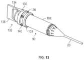
- FIG. 13 depicts a sensor unit of the monitoring device
- FIG. 14 depicts a part of the monitoring device including features forming a part turn lock for the sensor unit
- FIG. 15 depicts an alternative embodiment of the monitoring device
- FIGS. 16 and 17 depict load cell arrangements used in embodiments of the invention.
- FIG. 18 depicts another alternative sensor arrangement used in embodiments of the invention.
- FIG. 19 depicts a further embodiment of the monitoring device in a section through a plane parallel to the axis of the elongate member. For the sake of clarity, certain internal details of the monitoring device are omitted from this drawing.
- the first monitoring device 10 depicted in FIGS. 1 to 14 serves to monitor strain suffered by an elongate underwater member 12 , which may be any form of tubular member including a pipeline or riser, or may be any form of cable.
- the terms “radial” and “axial” are to be understood with reference to the elongate member 12 on which the monitoring device 10 is mounted.
- the axial direction extends generally along the length of the elongate member 10 .
- the radial direction extends laterally with respect to the elongate member 10 .
- the term “tangential” refers to a tangent to a circle around the elongate member 12 .
- the monitoring device 10 is configured as a clamp mechanism which is able to be fitted to the elongate member 12 in situ (although it can be fitted prior to deployment of the underwater member). That is, after the elongate member 12 has been deployed underwater, the monitoring device 10 is able to be attached to it. Further, the present embodiment is well suited to being fitted to the elongate member 12 by use of a remotely operated vehicle.
- the monitoring device 10 has first and second clamps 14 , 16 each of which embrace the elongate member 12 such as to be rigidly coupled to it and to move along with it.
- FIG. 2 provides a highly stylised representation of the clamp arrangement from which the manner of operation of the monitoring device 10 can be understood.
- the first and second clamps 14 , 16 are axially separated and are each intimately coupled to a respective region of the elongate member 12 . Changes of curvature of the elongate member 12 cause changes in the angle of the first clamp 14 with respect to the second clamp 16 , so by sensing that angle the strain suffered by the elongate member 12 can be determined.
- Measurement of the relevant angle is made using a sensor arrangement comprising a sensor actuator member 20 which is coupled to both the first clamp 14 and the second clamp 16 .
- One end of the sensor actuator member 20 is coupled to the second clamp 16 through a pivotal coupling 24 .
- the other end of the sensor actuator member 20 is coupled through an angle sensor 22 to the first clamp 14 .
- the angle sensor 22 provides an output representative of an angle between the sensor actuator member 20 and the first clamp 14 . Relative angular movement of the two clamps 14 , 16 due to changes of strain in the elongate member 12 is thus measurable through the angle sensor 22 .
- FIG. 3 represents a refinement of the FIG. 2 arrangement.
- the angle sensor 22 is carried on a rigid cantilevered limb 26 extending from the first clamp 14 toward the second clamp 16 , so that the angle sensor 22 is disposed mid-way between the clamps 14 , 16 .
- the result is that a given angular displacement of the first clamp 14 relative to the second clamp 16 produces a larger angular displacement of the parts of the angle sensor 22 .
- the provision of the cantilevered limb 26 improves the sensitivity and accuracy of the sensor arrangement.
- the same geometric effect could in other embodiments be achieved by mounting the pivotal coupling 24 on an arm cantilevered from the second clamp 16 .
- angle sensor 22 provides two outputs corresponding to angular position about two non-parallel (and typically perpendicular) axes, so that curvature of the elongate member 12 can be determined in two non-parallel (and typically perpendicular) planes.
- First clamp 14 comprises a rigid frame which is seen on its own in FIG. 6 and which in the present embodiment comprises metal and more specifically titanium.
- a first jaw assembly 28 is pivotally coupled to a second jaw assembly 30 by means of a through-going pivot rod 32 , so that the jaws can be opened to receive the elongate member 12 and then closed about it.
- the first jaw assembly 28 comprises (a) an outer lever portion comprising a parallel pair of shaped plates 36 , 38 coupled to one another through crossbars 40 and (b) an inner gripping portion shaped to embrace the elongate member 12 , having a part-circular inner edge, and formed by a single plate 42 .
- the second jaw assembly is somewhat similar in construction to the first, comprising an outer lever portion formed by a parallel pair of shaped plates 44 , 46 transitioning to an inner gripping portion formed by a single plate 48 .
- On either side of each of the single plates 42 , 48 is a respective shoulder portion 50 , 52 (see FIG. 1 ), these being secured to the single plates by through-rods 54 and shaped to form part-circular clamping faces 56 , 58 carrying in the present embodiment ribs 60 for engaging the elongate member 12 .
- a leaf spring 62 biases the clamp 14 toward a closed configuration (i.e. it biases the clamping faces 56 , 58 toward one another).
- the first jaw assembly 28 carries on its lever portion 36 , 38 a first clamping bar 64 .
- the second jaw assembly 30 carries on its lever portion 44 , 46 a second clamping bar 66 . Drawing the clamping bars 64 , 66 together opens the first clamp 14 against the force of the leaf spring 62 , enabling the clamp to be placed on the elongate member 12 , and releasing the clamping bars enables the clamp 14 to close around the elongate member 12 under the influence of the leaf spring 62 .
- a clamping screw 68 runs through the first and the second clamping bars 64 , 66 , being externally threaded and screwed into the first clamping bar 64 but forming a sliding fit in the second clamping bar 66 . While the clamping screw 68 is loose, it permits the clamp to open and close. But turning the clamping screw 68 causes it to urge the clamping bars 64 , 66 apart to securely clamp the first clamp 14 to the elongate member 12 .
- the clamping bars 64 , 66 of the first clamp 14 are seen to be coupled through grab bars 72 , 74 to the clamping bars 64 ′, 66 ′ of the second clamp.
- the grab bars 72 , 74 do not prevent angular movement of one clamp 14 relative to the other clamp 16 (as depicted in FIGS. 2 and 3 ). This may, for example, be because they are sufficiently compliant to bend when the clamps move.
- the grab bars are formed as compliant sleeves that receive the clamping bars 64 , 66 .
- the first and second clamps 14 , 16 are connected to one another in the present embodiment through flex links 76 , 78 , which in the present embodiment are roughly “X” shaped polymer components coupled to the single plates 42 , 48 . In this way the first and second clamps 14 , 16 are united to form a single assembly which is straightforward to manipulate prior to and during installation on the elongate member 12 .
- the flex links 76 , 78 also serve to define a spacing between the clamps prior to installation. But once the monitoring device 10 has been deployed, the flex links are sufficiently compliant to permit the clamps 14 , 16 to move relative to one another, in accordance with flexure of the elongate member 12 .
- the monitoring device 10 is able to be deployed straightforwardly subsea using an ROV (remotely operated vehicle).
- the device is first grasped by a manipulator of the ROV through the grab bars 72 , 74 , and is opened using the grab bars and placed around the elongate member 12 .
- Releasing the grab bars allows the clamps 14 , 16 to close around the elongate member 12 under the influence of the leaf springs 62 , so that the monitoring device 10 is able to maintain itself in position on the elongate member 12 .
- the ROV engages with fishtail torqueing features 80 of the clamping screws 68 and so turns the screws to tighten the clamps.
- the angle sensor 22 and associated electronics are contained in a sensor unit 90 which is depicted particularly in FIGS. 7 A- 7 C, 13 and 14 .
- the sensor unit 90 can be self-contained and self-powered. It can be sealed against ingress of water. It may take the form of a pressure vessel to protect the sensors and associated components from the effects of hydrostatic pressure.
- the sensor unit 90 may be mounted in such a manner as to enable it to be straightforwardly removed and replaced using an ROV. Thus, for example, it may be replaced when its batteries approach or reach the end of their operational lifetime, and it may be removed to enable logged data to be downloaded.
- a sensor body 92 of the sensor unit 90 is coupled to the sensor actuator member 20 in a manner which permits one to turn one somewhat relative to the other and it is the angle between the sensor body 92 and the sensor actuator member 20 that is measured to determine strain in the elongate member 12 .
- the coupling of the two parts is made through a ball and socket arrangement whose ball 94 is formed on an end of the sensor body 92 and whose socket 96 is formed in a frusto-conical cap portion 98 of the sensor actuator member 20 .
- the cap portion 98 is a separate component from the remainder of the sensor actuator member 20 , these parts being screwed together at 100 .
- a two-part collar 102 a , 102 b is secured to the cap portion 98 by threaded fasteners 104 and completes the socket 96 , rendering the ball 94 captive.
- a magnetic sensor arrangement is used to measure the angle between the sensor body 92 and the sensor actuator member 20 .
- One advantage of this is that the sensor arrangement itself does not rely on a physical connection between the sensor and the sensor actuator member 20 , so that the sensor itself and its associated electronics can be contained within the sealed vessel formed by the sensor unit 90 , and are thus not exposed to hydrostatic pressure nor to contamination or damage by any water-borne agents.
- a magnetic field is created by a magnet coupled to the sensor actuator member 20 . In the present embodiment, this comprises a stack of rare earth magnets 105 disposed in an axial bore in the cap portion 98 (see FIG. 7 B ). The magnetic field is sensed by a tri-axial magnetometer within the sensor unit 90 . The orientation of the field relative to the magnetometer varies with the angle between the sensor unit 90 and the sensor actuator member 20 , and this produces changes in the magnetometer's output. By suitable processing of the magnetometer output, the angle can thus be obtained.
- the sensor unit 90 comprises a hollow cylindrical housing 108 (see FIG. 7 C ) containing a battery pack 110 and circuit boards 112 .
- the sensor unit 90 is seen to be mounted to the first clamp 14 , and to project from it toward the second clamp 16 , thus serving the same function as the cantilevered limb 26 of FIG. 3 , bringing the pivotal coupling (item 24 in FIG. 3 , or equivalently the ball and socket arrangement 94 / 96 of the FIG. 7 embodiment) closer to the first clamp 16 , and so increasing the angular movement suffered by the sensor actuator member 20 in response to a given angular movement of the first clamp 14 relative to the second clamp 16 .
- the second clamp 16 carries a coupler 114 providing a conical internal cavity 116 into which the sensor actuator member 20 protrudes, being closely embraced by a waist portion 118 of the said internal cavity.
- the sensor actuator member's free end is coupled to the first clamp 14 such as to move along with it in response to strain suffered by the elongate member 12 .
- the waist portion locates the sensor actuator member 20 against movement relative to the second clamp 16 in the radial direction (arrow A in FIG. 5 A ) and in the tangential direction (that is, along a tangent to the axis of the elongate member 12 , i.e. perpendicular to the plane of the paper in FIG. 5 A ).
- the coupling provided by means of the coupler 114 accommodates both (a) angular movement of the clamp 16 relative to the sensor actuator member 20 and (b) axial movement of the clamp 16 relative to the sensor actuator member 20 (arrow B in FIG. 5 A , along the axis of the elongate member 12 ) which causes the sensor actuator member 20 to slide somewhat relative to the coupler 114 .
- a compliant sleeve 120 is provided around the sensor actuator member 20 , bridging the gap between the first and second clamps 14 , 16 and defining a largely enclosed volume 122 (see FIG. 9 ) around certain working parts of the sensor arrangement.
- this enclosed space is not sealed from the surrounding environment.
- the monitoring device 10 When the monitoring device 10 is submerged, it fills with water at the ambient pressure. But it is largely stagnant-water flow into/out of the volume 122 takes place only at a low rate, if at all. This makes it possible to maintain in the volume 122 a high concentration of an anti-fouling agent to resist growth of aquatic organisms which might otherwise impair the function of the sensor arrangement over time.
- a sacrificial coating of a suitable biocide may be provided on exposed surfaces in this region.
- Such coatings have a finite active lifetime, but their deployment in an essentially stagnant volume of water can greatly increase this lifetime.
- the compliant sleeve 120 is able to deform in accordance with movement of one clamp 14 relative to the other clamp 16 and so does not impede the required angular motion of the clamps.
- the sensor unit 90 is able to be removed from the remainder of the monitoring device 10 as seen in FIG. 8 . This is advantageous for several reasons.
- the batteries 110 have a finite lifetime. Periodically they require renewal. This can be easily accomplished by removing the sensor unit 90 and replacing it with another unit. The original unit may then have its batteries replaced and be returned to service.
- the sensor unit 90 preferably logs sensor data onboard. One convenient way to retrieve the data is to retrieve the entire sensor unit 90 . Also, any failed sensor unit 90 may be straightforwardly replaced without the need to replace the entire monitoring unit 10 .
- the sensor unit 90 is inserted into a complementary socket 124 in the second clamp 16 , and is retained in it by a part turn lock mechanism, which could also be referred to as a bayonet mechanism.
- the socket comprises a wall 126 with a cutaway 128 to receive a follower 130 of a handle assembly 132 carried by the sensor unit 90 .
- the handle mechanism comprises a mounting ring 133 secured to the sensor body 92 and carrying multiple upstanding bolts 134 which pass through a sprung ring 136 which carries a handle portion 138 .
- Helical springs 140 bias the sprung ring 136 away from the mounting ring 133 .
- the sprung ring 136 On an outer face the sprung ring 136 carries the follower 130 .
- the follower 130 Upon insertion of the sensor unit 90 into the socket 124 , the follower 130 is introduced to the cutaway 128 .
- the springs 140 are compressed.
- the sensor unit 90 can then be turned through a small angle until the follower aligns with a short, blind return 144 of the cutaway, into which the follower is urged by the springs to lock the sensor unit in position. Note—with reference to FIG. 8 —that simply advancing the sensor unit 90 into the socket 124 causes the sensor actuator member 20 to be received by the coupler 114 .
- the illustrated part turn lock mechanism is only one example of a suitable means for retaining the sensor unit 90 . Another possibility is to provide some form of snap fit mechanism. Various alternatives will present themselves to the skilled person.
- the coupling 114 is also able to be easily removed for replacement, inspection or refurbishment. Referring to FIG. 8 , it is received in a socket 146 of the second clamp 16 , and is provided with a handle 148 and a part turn lock mechanism of the same form as the one already described.
- the use of a magnetometer to determine angle between the first and second clamps is especially advantageous. It permits the required angle sensor (the magnetometer itself) to be housed inside the sealed housing 108 which can be formed as a pressure vessel able to withstand the potentially large hydrostatic pressure suffered by the device. No mechanical connection from the interior to the exterior of the housing 108 is needed to actuate the sensor. Provision of such a connection might provide a potential route for ingress of water, or might otherwise contribute unwanted stiffness which would inhibit the sensor's action.
- the magnetometer can be a compact and reliable MEMs (micro-mechanical) type of device—suitable magnetometers are commercially available. Such a magnetometer can have a low power requirement, helping to maximise battery lifetime which, since visits to the device may be infrequent and expensive, is an important design factor.
- the magnetic sensor arrangement used in the above described embodiment may be replaced, in other embodiments, with a different type of sensor arrangement for measuring the angle between the two clamps 14 , 16 .
- FIG. 10 depicts an alternative sensor arrangement which uses linear sensors to detect the position of the sensor actuator member 20 .
- the sensor actuator member 20 passes through a locating arrangement 160 which locates it laterally whilst permitting angular movement.
- This uses a spherical joint in the present embodiment, the sensor actuator member 20 passing through an opening in ball 162 of the joint.
- This configuration is often referred to as a rose joint (UK) or a heim joint (North America).
- the sensor actuator member 20 couples to a set of linear position sensors 164 .
- a cage structure 166 carries both the position sensors 164 and the locating arrangement 160 .
- the position sensors 164 are directed laterally with respect to the sensor actuator member 20 , and are operatively coupled to it, so that angular movement of the sensor actuator member 20 causes a linear displacement along the direction of action of the sensor. Hence the sensor output can be used to determine the angular position of the sensor actuator member 20 , and this data can be used to calculate strain suffered by the elongate member 12 .
- there are two parallel pairs of position sensors 164 but this provides some redundancy—a functioning device could be constructed using just two position sensors 164 oriented along different (preferably perpendicular) directions.
- FIG. 11 represents a further alternative sensor arrangement in which the sensor actuator member 20 is cantilevered from a dual axis load cell 168 .
- the load cell has a cruciform support structure formed by four arms 170 radiating from a boss 172 from which the sensor actuator member 20 is cantilevered.
- the arms 170 meet an outer frame 174 .
- Strain gauges 176 , 178 are mounted to the load cell 168 to detect deformation created by movement of the sensor actuator member 20 .
- the outputs of the strain gauges 176 , 178 can be used to determine the orientation of the sensor actuator member 20 , and from that data the strain suffered by the elongate member 12 can be calculated.
- FIGS. 16 and 17 represent alternative forms of the load cell.
- the load cell 168 a depicted in FIG. 16 has a rigid circular periphery with a cruciform arrangement of arms 170 a radiating from a boss 172 a and carrying strain gauges 176 a .
- the load cell 168 b depicted in FIG. 17 has a rigid circular periphery supporting a disc 170 b which carries the boss 172 b , and strain gauges 176 b are provided on the disc to sense its deformation under bending load.
- FIG. 12 represents another alternative sensor arrangement using first and second rotary position sensors 180 , 182 in a form of a gimbal mechanism to determine the angular position of the sensor actuator member 20 .
- the sensor actuator member 20 is cantilevered from a central mount 184 which is rotatable about a first axis with respect to a gimbal member 186 .
- Rotary position of the sensor actuator member with respect to the first axis is determined by first rotary position sensor 180 .
- the gimbal member 186 is rotatable about a second axis (which is perpendicular to the first axis in the present embodiment) with respect to a frame 188 and rotary position of the sensor actuator member 20 with respect to the second axis is determined by second rotary position sensor 182 . From the outputs of the rotary position sensors 180 , 182 , the angular position of the sensor actuator member 20 can be found, and from that data the strain suffered by the elongate member 12 can be calculated.
- FIG. 18 represents still another sensor arrangement.
- a movable plate 300 is threaded at 301 to receive the sensor actuator member 20 and is able to turn somewhat along with it.
- the movable plate 300 is linked to a base plate 302 through a set of strain gauges 304 extending across a gap between the plates, so that angular movement of the movable plate 300 changes the strains suffered by the gauges 304 , and so from the gauge outputs the angle of the movable plate 300 can be obtained.
- the monitoring device 10 may incorporate any of a range of additional sensors to monitor further operational parameters of the elongate member 12 and/or its environment. Without limitation, these may include any of the following:
- the monitoring device 10 generates sensor data which is (a) logged and (b) communicated to a separate processing device.
- logging period may be fixed or variable, and will typically be determined taking account of factors including frequency of any expected cyclical movement and battery lifetime.
- battery lifetime may be extended by harvesting of energy from the environment, e.g. by use of photovoltaic cells (where the environment provides sufficient light), thermoelectric generators, or triboelectric or piezoelectric generators.
- the sensor unit 90 comprises on-board memory capacity for logging sensor data. It may also comprise an on-board processing device to process sensor data, reducing the quantity of data that needs to be exported from the sensor unit 90 .
- a communications interface is provided for exporting sensor data to a separate processing system.
- the present invention is not limited to use of any specific mode of communication.
- Data may for example be exported through a radio link, through an optical link, through an acoustic link or through a physical connection which could comprise an electrical wire or optical fibre.
- data is to be retrieved from the sensor unit 90 through a short range link. This may for example be carried out using an ROV which visits the site and collects sensor data.
- FIGS. 2 and 3 may be put into practice using a whole range of different physical embodiments.
- the clamps may take any of a range of different forms. They could for example take the form of band clamps.
- FIG. 15 provides just one example of an alternative mode of implementation of the present invention.
- the first clamp 214 comprises a stiff hinged framework 200 a , 200 b .
- the second clamp 216 comprises a pair of elastomer jaws.
- the sensor actuator member 20 is not seen in this drawing but is coupled between the clamps 214 , 216 as before.
- the further embodiment 10a of the monitoring device is in most respects similar to the first embodiment and like parts are given the same reference numerals.
- the monitoring device 10 a differs from the above-described monitoring device 10 in that the actuator member 20 terminates in an enlarged piston head 300 received in a cylinder 302 , so that the piston head 300 is able to move somewhat during flexure of the elongate member 12 .
- FIG. 19 also serves to represent the location of sensing magnetometer 304 which, by sensing the magnetic field of the magnets 105 , provides the sensor's output.
- the sensing magnetometer 304 is positioned in this embodiment at the centre of the ball 94 , so that its separation from the magnets 105 does not vary with angle.
- the present embodiment further comprises a compensation magnetometer 306 positioned remotely from the magnets 105 .
- the monitoring device 10 a may be subject, in practice, to externally generated magnetic fields, e.g. due to magnetisation of metal components of the elongate member 12 . These externally generated fields may affect the signal from the sensing magnetometer 304 , having a deleterious effect on its accuracy.
- the compensation magnetometer 306 senses such externally generated fields, and makes it possible to compensate for them. Most straightforwardly, compensation may involve deducting the output of the compensation magnetometer 306 from the output of the sensing magnetometer 304 .
Landscapes
- Physics & Mathematics (AREA)
- Engineering & Computer Science (AREA)
- Life Sciences & Earth Sciences (AREA)
- Mining & Mineral Resources (AREA)
- Geology (AREA)
- Geochemistry & Mineralogy (AREA)
- Environmental & Geological Engineering (AREA)
- Fluid Mechanics (AREA)
- General Physics & Mathematics (AREA)
- General Life Sciences & Earth Sciences (AREA)
- Geophysics (AREA)
- Aviation & Aerospace Engineering (AREA)
- Mechanical Engineering (AREA)
- Electromagnetism (AREA)
- General Engineering & Computer Science (AREA)
- Testing Or Calibration Of Command Recording Devices (AREA)
- Measuring Magnetic Variables (AREA)
- Investigating Strength Of Materials By Application Of Mechanical Stress (AREA)
Abstract
Description
-
- an accelerometer to determine acceleration of the
elongate member 12 and in some embodiments its position and/or its orientation; - a gyroscopic sensor;
- one or more temperature sensors responsive to environmental temperature (water temperature) and/or surface temperature of the
elongate member 12; - one or more pressure sensors responsive to external hydrostatic pressure, from which depth can be determined.
- an accelerometer to determine acceleration of the
Claims (18)
Applications Claiming Priority (4)
| Application Number | Priority Date | Filing Date | Title |
|---|---|---|---|
| GB2002029 | 2020-02-14 | ||
| GB2002029.3 | 2020-02-14 | ||
| GBGB2002029.3A GB202002029D0 (en) | 2020-02-14 | 2020-02-14 | A device for monitoring strain of an elongate underwater member |
| PCT/GB2021/050331 WO2021161025A1 (en) | 2020-02-14 | 2021-02-11 | A device for monitoring strain of an elongate underwater member |
Publications (2)
| Publication Number | Publication Date |
|---|---|
| US20230089102A1 US20230089102A1 (en) | 2023-03-23 |
| US12228463B2 true US12228463B2 (en) | 2025-02-18 |
Family
ID=69956485
Family Applications (1)
| Application Number | Title | Priority Date | Filing Date |
|---|---|---|---|
| US17/904,268 Active 2041-07-25 US12228463B2 (en) | 2020-02-14 | 2021-02-11 | Device for monitoring strain of an elongate underwater member |
Country Status (4)
| Country | Link |
|---|---|
| US (1) | US12228463B2 (en) |
| AU (1) | AU2021219333B2 (en) |
| GB (2) | GB202002029D0 (en) |
| WO (1) | WO2021161025A1 (en) |
Families Citing this family (1)
| Publication number | Priority date | Publication date | Assignee | Title |
|---|---|---|---|---|
| GB2632944A (en) * | 2022-04-21 | 2025-02-26 | Advanced Innergy Solutions Ltd | Magnetic inspection and monitoring device for a pipe |
Citations (15)
| Publication number | Priority date | Publication date | Assignee | Title |
|---|---|---|---|---|
| US4663975A (en) | 1984-03-02 | 1987-05-12 | British Gas Corporation | Vibratory wire strain gauge assemblies for underwater attachment |
| WO2006050488A1 (en) | 2004-11-03 | 2006-05-11 | Shell Internationale Research Maatschappij B.V. | Apparatus and method for retroactively installing sensors on marine elements |
| WO2008021881A2 (en) | 2006-08-09 | 2008-02-21 | Shell Oil Company | Method of applying a string of interconnected strain sensors to an object, a pliable support structure, and method of producing a mineral hydrocarbon fluid |
| US20080303382A1 (en) | 2007-06-11 | 2008-12-11 | Bmt Scientific Marine Services, Inc. | Device and method for providing strain measurements of insulated pipes |
| GB2454220A (en) * | 2007-11-01 | 2009-05-06 | Schlumberger Holdings | Detecting strain in structures |
| GB2457277A (en) * | 2008-02-08 | 2009-08-12 | Schlumberger Holdings | Methods and apparatuses for detecting strain in structures |
| WO2009156486A1 (en) | 2008-06-26 | 2009-12-30 | Services Petroliers Schlumberger | System and method for monitoring bending of a flexible riser |
| WO2010028387A2 (en) | 2008-09-08 | 2010-03-11 | Schlumberger Technology Corporation | System and method for detection of flexible pipe armor wire ruptures |
| GB2456830B (en) | 2008-01-28 | 2012-03-14 | Schlumberger Holdings | Structural load monitoring using collars and connecting elements with strain sensors |
| WO2016166505A1 (en) | 2015-04-16 | 2016-10-20 | Expro North Sea Limited | Measurement system and methods |
| WO2017065961A1 (en) | 2015-10-15 | 2017-04-20 | Schlumberger Technology Corporation | Intelligent drilling riser |
| CN108072352A (en) | 2017-12-13 | 2018-05-25 | 中国飞机强度研究所 | A kind of shaft position sensor clamping device |
| CN208366511U (en) | 2018-07-17 | 2019-01-11 | 大连理工大学 | A kind of cable force monitoring device based on fiber-optic grating sensor |
| GB2566001A (en) | 2017-06-05 | 2019-03-06 | Cowin Neil | Condition monitoring device and safety system |
| WO2020037388A1 (en) | 2018-08-18 | 2020-02-27 | Monflex Tec Engenharia De Integridade Ltda. | System for monitoring the integrity of risers and maritime structures using deformation sensors installed by clamps, and methods for installing and calibrating the pre-tension on deformation sensors for monitoring the integrity of risers |
-
2020
- 2020-02-14 GB GBGB2002029.3A patent/GB202002029D0/en not_active Ceased
-
2021
- 2021-02-11 AU AU2021219333A patent/AU2021219333B2/en active Active
- 2021-02-11 GB GB2212777.3A patent/GB2607820B/en active Active
- 2021-02-11 US US17/904,268 patent/US12228463B2/en active Active
- 2021-02-11 WO PCT/GB2021/050331 patent/WO2021161025A1/en not_active Ceased
Patent Citations (15)
| Publication number | Priority date | Publication date | Assignee | Title |
|---|---|---|---|---|
| US4663975A (en) | 1984-03-02 | 1987-05-12 | British Gas Corporation | Vibratory wire strain gauge assemblies for underwater attachment |
| WO2006050488A1 (en) | 2004-11-03 | 2006-05-11 | Shell Internationale Research Maatschappij B.V. | Apparatus and method for retroactively installing sensors on marine elements |
| WO2008021881A2 (en) | 2006-08-09 | 2008-02-21 | Shell Oil Company | Method of applying a string of interconnected strain sensors to an object, a pliable support structure, and method of producing a mineral hydrocarbon fluid |
| US20080303382A1 (en) | 2007-06-11 | 2008-12-11 | Bmt Scientific Marine Services, Inc. | Device and method for providing strain measurements of insulated pipes |
| GB2454220A (en) * | 2007-11-01 | 2009-05-06 | Schlumberger Holdings | Detecting strain in structures |
| GB2456830B (en) | 2008-01-28 | 2012-03-14 | Schlumberger Holdings | Structural load monitoring using collars and connecting elements with strain sensors |
| GB2457277A (en) * | 2008-02-08 | 2009-08-12 | Schlumberger Holdings | Methods and apparatuses for detecting strain in structures |
| WO2009156486A1 (en) | 2008-06-26 | 2009-12-30 | Services Petroliers Schlumberger | System and method for monitoring bending of a flexible riser |
| WO2010028387A2 (en) | 2008-09-08 | 2010-03-11 | Schlumberger Technology Corporation | System and method for detection of flexible pipe armor wire ruptures |
| WO2016166505A1 (en) | 2015-04-16 | 2016-10-20 | Expro North Sea Limited | Measurement system and methods |
| WO2017065961A1 (en) | 2015-10-15 | 2017-04-20 | Schlumberger Technology Corporation | Intelligent drilling riser |
| GB2566001A (en) | 2017-06-05 | 2019-03-06 | Cowin Neil | Condition monitoring device and safety system |
| CN108072352A (en) | 2017-12-13 | 2018-05-25 | 中国飞机强度研究所 | A kind of shaft position sensor clamping device |
| CN208366511U (en) | 2018-07-17 | 2019-01-11 | 大连理工大学 | A kind of cable force monitoring device based on fiber-optic grating sensor |
| WO2020037388A1 (en) | 2018-08-18 | 2020-02-27 | Monflex Tec Engenharia De Integridade Ltda. | System for monitoring the integrity of risers and maritime structures using deformation sensors installed by clamps, and methods for installing and calibrating the pre-tension on deformation sensors for monitoring the integrity of risers |
Non-Patent Citations (2)
| Title |
|---|
| GB Search Report mailed on Jul. 20, 2020, issued in GB Application No. GB2002029.3, filed on Feb. 14, 2020, 6 pages. |
| PCT International Search Report and Written Opinion, mailed on Jul. 13, 2021 issued in International Application No. PCT/GB2021/050331, filed on Feb. 11, 2021, 19 pages. |
Also Published As
| Publication number | Publication date |
|---|---|
| WO2021161025A1 (en) | 2021-08-19 |
| US20230089102A1 (en) | 2023-03-23 |
| GB2607820B (en) | 2024-02-21 |
| GB202002029D0 (en) | 2020-04-01 |
| GB2607820A (en) | 2022-12-14 |
| GB202212777D0 (en) | 2022-10-19 |
| AU2021219333A1 (en) | 2022-09-29 |
| AU2021219333B2 (en) | 2026-01-29 |
Similar Documents
| Publication | Publication Date | Title |
|---|---|---|
| CN102654051B (en) | For measuring equipment and the method for the weight at down well placement and moment of torsion | |
| US6941793B2 (en) | Impulse generator for profiling system | |
| DK1839052T3 (en) | INSTRUMENTATION PROBLEMS FOR IN SITU MEASUREMENT AND TESTING OF THE SEA | |
| CN110192001B (en) | Sensor for a rotatable element | |
| AU2005315422A1 (en) | Structural joint strain monitoring apparatus and system | |
| CN109001829A (en) | Strapdown underwater dynamic gravity measuring instrument | |
| US12228463B2 (en) | Device for monitoring strain of an elongate underwater member | |
| CN106884648B (en) | Engineering parameter measurement while drilling device for deep water drill string | |
| EP1840501A2 (en) | Curvature sensor | |
| US11530578B2 (en) | Bend stiffener | |
| CA2980236C (en) | Measurement system and methods | |
| CA1224064A (en) | Vibratory wire strain gauge assemblies for underwater attachment | |
| GB2561196A (en) | Subsea pipeline buoyancy module | |
| US20240117733A1 (en) | A downhole assembly with spring isolation filter | |
| CN216118035U (en) | A submarine seismic monitoring device | |
| Deffenbaugh et al. | An untethered sensor for well logging | |
| US20230067262A1 (en) | Buoyancy module | |
| WO2019028500A1 (en) | Sensor module for a marine buoyancy unit and a system and method for using the same | |
| US20230101296A1 (en) | Cladding | |
| CN112697059A (en) | Optical fiber ground deformation sensor for underwater soft medium | |
| EP4526205B1 (en) | Apparatus, system and method for monitoring a subsea load | |
| CA3216821C (en) | A downhole assembly with spring isolation filter | |
| US20250060207A1 (en) | Shape Estimation of Structures Undergoing Dynamic Stress | |
| CN118135764A (en) | Method for monitoring landslide through geomagnetic technology | |
| Asakawa et al. | Evaluation of small models of ceramic housings for 11,000 m ocean bottom seismometers |
Legal Events
| Date | Code | Title | Description |
|---|---|---|---|
| FEPP | Fee payment procedure |
Free format text: ENTITY STATUS SET TO UNDISCOUNTED (ORIGINAL EVENT CODE: BIG.); ENTITY STATUS OF PATENT OWNER: LARGE ENTITY |
|
| STPP | Information on status: patent application and granting procedure in general |
Free format text: DOCKETED NEW CASE - READY FOR EXAMINATION |
|
| STPP | Information on status: patent application and granting procedure in general |
Free format text: NON FINAL ACTION MAILED |
|
| STPP | Information on status: patent application and granting procedure in general |
Free format text: RESPONSE TO NON-FINAL OFFICE ACTION ENTERED AND FORWARDED TO EXAMINER |
|
| STPP | Information on status: patent application and granting procedure in general |
Free format text: NOTICE OF ALLOWANCE MAILED -- APPLICATION RECEIVED IN OFFICE OF PUBLICATIONS |
|
| AS | Assignment |
Owner name: ADVANCED INNERGY LIMITED, UNITED KINGDOM Free format text: ASSIGNMENT OF ASSIGNORS INTEREST;ASSIGNORS:TWELVETREES, WILL;HARBISON, AUSTIN;SIGNING DATES FROM 20241217 TO 20250106;REEL/FRAME:069788/0901 Owner name: CHEVRON U.S.A. INC., CALIFORNIA Free format text: ASSIGNMENT OF ASSIGNORS INTEREST;ASSIGNORS:CRITSINELIS, ANTONIO;CONSTANTINIDES, YIANNIS;MEBARKIA, SID;SIGNING DATES FROM 20241119 TO 20241122;REEL/FRAME:069789/0043 |
|
| STPP | Information on status: patent application and granting procedure in general |
Free format text: PUBLICATIONS -- ISSUE FEE PAYMENT VERIFIED |
|
| STCF | Information on status: patent grant |
Free format text: PATENTED CASE |