US12223422B2 - Continuous training methods for systems identifying anomalies in an image of an object - Google Patents
Continuous training methods for systems identifying anomalies in an image of an object Download PDFInfo
- Publication number
- US12223422B2 US12223422B2 US17/062,019 US202017062019A US12223422B2 US 12223422 B2 US12223422 B2 US 12223422B2 US 202017062019 A US202017062019 A US 202017062019A US 12223422 B2 US12223422 B2 US 12223422B2
- Authority
- US
- United States
- Prior art keywords
- anomaly
- image
- model
- encoder
- types
- Prior art date
- Legal status (The legal status is an assumption and is not a legal conclusion. Google has not performed a legal analysis and makes no representation as to the accuracy of the status listed.)
- Active, expires
Links
Images


Classifications
-
- G—PHYSICS
- G06—COMPUTING OR CALCULATING; COUNTING
- G06N—COMPUTING ARRANGEMENTS BASED ON SPECIFIC COMPUTATIONAL MODELS
- G06N3/00—Computing arrangements based on biological models
- G06N3/02—Neural networks
- G06N3/08—Learning methods
-
- G—PHYSICS
- G06—COMPUTING OR CALCULATING; COUNTING
- G06N—COMPUTING ARRANGEMENTS BASED ON SPECIFIC COMPUTATIONAL MODELS
- G06N3/00—Computing arrangements based on biological models
- G06N3/02—Neural networks
- G06N3/08—Learning methods
- G06N3/088—Non-supervised learning, e.g. competitive learning
-
- G—PHYSICS
- G06—COMPUTING OR CALCULATING; COUNTING
- G06N—COMPUTING ARRANGEMENTS BASED ON SPECIFIC COMPUTATIONAL MODELS
- G06N3/00—Computing arrangements based on biological models
- G06N3/02—Neural networks
- G06N3/04—Architecture, e.g. interconnection topology
- G06N3/045—Combinations of networks
- G06N3/0455—Auto-encoder networks; Encoder-decoder networks
-
- G—PHYSICS
- G06—COMPUTING OR CALCULATING; COUNTING
- G06N—COMPUTING ARRANGEMENTS BASED ON SPECIFIC COMPUTATIONAL MODELS
- G06N3/00—Computing arrangements based on biological models
- G06N3/02—Neural networks
- G06N3/04—Architecture, e.g. interconnection topology
- G06N3/047—Probabilistic or stochastic networks
-
- G—PHYSICS
- G06—COMPUTING OR CALCULATING; COUNTING
- G06N—COMPUTING ARRANGEMENTS BASED ON SPECIFIC COMPUTATIONAL MODELS
- G06N3/00—Computing arrangements based on biological models
- G06N3/02—Neural networks
- G06N3/04—Architecture, e.g. interconnection topology
- G06N3/0475—Generative networks
-
- G—PHYSICS
- G06—COMPUTING OR CALCULATING; COUNTING
- G06N—COMPUTING ARRANGEMENTS BASED ON SPECIFIC COMPUTATIONAL MODELS
- G06N3/00—Computing arrangements based on biological models
- G06N3/02—Neural networks
- G06N3/08—Learning methods
- G06N3/0895—Weakly supervised learning, e.g. semi-supervised or self-supervised learning
-
- G—PHYSICS
- G06—COMPUTING OR CALCULATING; COUNTING
- G06N—COMPUTING ARRANGEMENTS BASED ON SPECIFIC COMPUTATIONAL MODELS
- G06N3/00—Computing arrangements based on biological models
- G06N3/02—Neural networks
- G06N3/08—Learning methods
- G06N3/09—Supervised learning
-
- G—PHYSICS
- G06—COMPUTING OR CALCULATING; COUNTING
- G06N—COMPUTING ARRANGEMENTS BASED ON SPECIFIC COMPUTATIONAL MODELS
- G06N3/00—Computing arrangements based on biological models
- G06N3/02—Neural networks
- G06N3/08—Learning methods
- G06N3/094—Adversarial learning
-
- G—PHYSICS
- G06—COMPUTING OR CALCULATING; COUNTING
- G06V—IMAGE OR VIDEO RECOGNITION OR UNDERSTANDING
- G06V10/00—Arrangements for image or video recognition or understanding
- G06V10/70—Arrangements for image or video recognition or understanding using pattern recognition or machine learning
- G06V10/77—Processing image or video features in feature spaces; using data integration or data reduction, e.g. principal component analysis [PCA] or independent component analysis [ICA] or self-organising maps [SOM]; Blind source separation
- G06V10/774—Generating sets of training patterns; Bootstrap methods, e.g. bagging or boosting
- G06V10/7753—Incorporation of unlabelled data, e.g. multiple instance learning [MIL]
-
- G—PHYSICS
- G06—COMPUTING OR CALCULATING; COUNTING
- G06V—IMAGE OR VIDEO RECOGNITION OR UNDERSTANDING
- G06V10/00—Arrangements for image or video recognition or understanding
- G06V10/70—Arrangements for image or video recognition or understanding using pattern recognition or machine learning
- G06V10/82—Arrangements for image or video recognition or understanding using pattern recognition or machine learning using neural networks
-
- G—PHYSICS
- G06—COMPUTING OR CALCULATING; COUNTING
- G06N—COMPUTING ARRANGEMENTS BASED ON SPECIFIC COMPUTATIONAL MODELS
- G06N3/00—Computing arrangements based on biological models
- G06N3/02—Neural networks
- G06N3/08—Learning methods
- G06N3/084—Backpropagation, e.g. using gradient descent
Definitions
- the present technology relates to the field of computer assisted image inspection.
- the present technology introduces continuous training methods for systems identifying anomalies in an image of an object.
- Unsupervised and semi-supervised visual anomaly detection and classification pose very challenging problems. Some problems are related to the fact that, in most circumstances, labeling image data is cost prohibitive. Other problems are related to the fact that many defects in manufactured goods are very small and difficult to detect using visual anomaly detection mechanisms. Also, the nature of the defects tends to change over time and new types of defects may frequently occur. Consequently, conventional imaging solutions either require huge amounts of expensive labeled data that may actually be inaccurate. Also, conventional imaging solutions frequently become obsolete as new types of defects are discovered. Models used by these conventional imaging solutions need to be taken out of service and replaced with updated models. Such solutions are not scalable, are costly, and are therefore not sustainable in practice.
- Embodiments of the present technology have been developed based on developers' appreciation of shortcomings associated with the prior art.
- Such shortcomings may comprise high costs of labeling image data, lack of updatability to cater for new types of defects, and/or lack of scalability.
- various implementations of the present technology provide a computer-implemented continuous training method for a system identifying anomalies in an image of an object, comprising:
- the model of the object is a flow-based model.
- the model of the object is a generative adversarial network model.
- the model of the object is a variational autoencoder model.
- training the system further comprises using classification information for each of the one or more first anomaly types when forming the model of the object in the latent space; and retraining the system further comprises using classification information for each of the one or more first anomaly types and for each of the one or more second anomaly types when updating the model of the object in the latent space.
- the method further comprises supplying, to a classifier, a first label for each image among the one or more first sets of images; calculating, by the classifier, a first classification loss for each of the first anomaly types; using the first classification losses for training the system; supplying, to the classifier a second label for each image among the one or more second sets of images; calculating, by the classifier, a classification loss for each of the second anomaly types; and using the classification losses for retraining the system.
- the method further comprises supplying, to the classifier, a content of the latent space; using, at the classifier, the content of the latent space to classify each of the one or more first anomaly types for the object; and using, at the classifier, the content of the latent space to classify each of the one or more second anomaly types for the object.
- the content of the latent space supplied to the classifier is a portion of the latent space.
- the retraining of the system is performed without downtime of the system.
- training the system further comprises: supplying, to an image encoder the system, a set of anomaly-free images of an object; encoding, by the image encoder, each anomaly free image of the object to form a corresponding image model in the latent space; generating, in an image decoder of the system, an output image corresponding to each of the image models; and calculating, in the system, a reconstruction loss based on a norm of differences between each anomaly-free image of the object and the corresponding output image.
- the anomaly-free images of the object are augmented images.
- training the system further comprises calculating a regularization loss based on a ratio of an output of a previous layer of the model of the object of the object over an output of a current layer of the model of the object.
- the images of the one or more first sets of images corresponding to the one or more first anomaly types for the object and the images of the one or more second sets of images corresponding to the one or more second anomaly types for the object are augmented images.
- each augmented image is obtained by adding thereto an alteration selected from a random noise, a random cropping, a random rotation, a random set of white patches, a random set of black patches and a combination thereof.
- various implementations of the present technology provide a system for identifying anomalies in an object, comprising:
- the system further comprises an image decoder, the image encoder implementing a first function; the image decoder implementing a second function, the second function being an inverse of the first function; and the image encoder and the image decoder sharing a common set of weights.
- the system further comprises an input interface operatively connected to the image encoder; and an output interface operatively connected to the decoder; the input interface being adapted to receive an input image of the object from an image source and to provide the input image to the image encoder; the image encoder being adapted to generate an image model based on the input image of the object; the image decoder being adapted to generate a decoded image of the object based on the image model; and the output interface being adapted to transmit the decoded image of the object to an image receiver.
- computer-readable medium and “memory” are intended to include media of any nature and kind whatsoever, non-limiting examples of which include RAM, ROM, disks (CD-ROMs, DVDs, floppy disks, hard disk drives, etc.), USB keys, flash memory cards, solid state-drives, and tape drives. Still in the context of the present specification, “a” computer-readable medium and “the” computer-readable medium should not be construed as being the same computer-readable medium. To the contrary, and whenever appropriate, “a” computer-readable medium and “the” computer-readable medium may also be construed as a first computer-readable medium and a second computer-readable medium.
- Implementations of the present technology each have at least one of the above-mentioned objects and/or aspects, but do not necessarily have all of them. It should be understood that some aspects of the present technology that have resulted from attempting to attain the above-mentioned object may not satisfy this object and/or may satisfy other objects not specifically recited herein.
- FIG. 1 is a block diagram of an anomaly detection system adapted to be trained in unsupervised mode in accordance with an embodiment of the present technology
- FIG. 2 is a block diagram of an anomaly detection system adapted to be trained in semi-supervised mode in accordance with an embodiment of the present technology
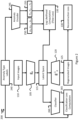
- FIG. 3 is a block diagram of an anomaly detection system adapted to be trained in semi-supervised mode and retrained using a continuous learning feature in accordance with an embodiment of the present technology
- FIG. 4 is a block diagram showing interactions between the anomaly detection system of any one of FIGS. 1 , 2 and 3 and a training engine in accordance with an embodiment of the present technology
- FIG. 5 is the anomaly detection system of any one of FIGS. 1 , 2 and 3 in use for identifying anomalies in an object in accordance with an embodiment of the present technology
- FIG. 6 is a sequence diagram showing operations of a method for identifying anomalies in an object in accordance with an embodiment of the present technology
- FIG. 7 is a sequence diagram showing operations of a method for training the anomaly detection system of FIG. 1 in an object in accordance with an embodiment of the present technology
- FIGS. 8 a and 8 b are a sequence diagram showing operations of a method for training the anomaly detection system of FIG. 2 or 3 in an object in accordance with an embodiment of the present technology
- FIGS. 9 a and 9 b are a sequence diagram showing operations of a method for retraining the anomaly detection system of FIG. 3 in an object in accordance with an embodiment of the present technology
- FIG. 10 is a block diagram showing internal components of the anomaly detection system according to any one of FIGS. 1 , 2 and 3 in accordance with an embodiment of the present technology
- FIG. 11 illustrates a first object having anomalies and a heat-map displaying anomaly probabilities on the first object, the heat-map being generated accordance with an embodiment of the present technology
- FIG. 12 illustrates a second object having anomalies and a heat-map displaying anomaly probabilities on the second object, the heat-map being generated accordance with an embodiment of the present technology
- FIG. 13 illustrates a third object having anomalies and a heat-map displaying anomaly probabilities on the third object, the heat-map being generated accordance with an embodiment of the present technology
- FIG. 14 illustrates a fourth object having anomalies and a heat-map displaying anomaly probabilities on the fourth object for a set of anomaly types, the heat-map being generated accordance with an embodiment of the present technology
- FIG. 15 illustrates the fourth object of FIG. 14 having new anomalies and a heat-map displaying anomaly probabilities on the fourth object for another set of anomaly types, the heat-map being generated accordance with an embodiment of the present technology.
- processor may be provided through use of dedicated hardware as well as hardware capable of executing software in association with appropriate software.
- the functions may be provided by a single dedicated processor, by a single shared processor, or by a plurality of individual processors, some of which may be shared.
- the processor may be a general-purpose processor, such as a central processing unit (CPU) or a processor dedicated to a specific purpose, such as a digital signal processor (DSP).
- CPU central processing unit
- DSP digital signal processor
- processor should not be construed to refer exclusively to hardware capable of executing software, and may implicitly include, without limitation, application specific integrated circuit (ASIC), field programmable gate array (FPGA), read-only memory (ROM) for storing software, random access memory (RAM), and non-volatile storage. Other hardware, conventional and/or custom, may also be included.
- ASIC application specific integrated circuit
- FPGA field programmable gate array
- ROM read-only memory
- RAM random access memory
- non-volatile storage non-volatile storage.
- Other hardware conventional and/or custom, may also be included.
- modules may be represented herein as any combination of flowchart elements or other elements indicating performance of process steps and/or textual description. Such modules may be executed by hardware that is expressly or implicitly shown. Moreover, it should be understood that such modules may include for example, but without being limitative, computer program logic, computer program instructions, software, stack, firmware, hardware circuitry or a combination thereof which provides the required capabilities.
- the present technology may operate in unsupervised mode for identifying image anomalies.
- a system has been trained using a set of anomaly-free images of an object. Having learned a rich representation of the non-anomalous object, the system is able to receive an input image of a particular object that may contain anomalies, generate an image model and regenerate a substitute non-anomalous image of the object.
- An anomaly map for example a heat-map, may be generated by comparing the input image and the regenerated image. Areas in the anomaly map that are associated with high probabilities represent parts of the object that most likely contain anomalies. The anomaly map may thus localize the anomalies defect while providing a confidence level for the detection of anomalies.
- the present technology may operate in semi-supervised mode.
- the system is trained in unsupervised mode using the set of anomaly-free images of the object, in the manner expressed in the previous paragraph.
- a classification head is added to the system.
- the classification head having been trained in supervised mode using a small label dataset of anomalous images of the object, it may predict with increased performance and accuracy a type of an anomaly in the input image of the particular object, directly from the generated image model.
- the size of the label dataset may be much smaller than the set of anomaly-free images used for training in unsupervised mode. Therefore, this semi-supervised technique may be used both for anomaly detection with localization and for anomaly-type classification.
- the present technology may use a continuous mode for training the system, both in the unsupervised and semi-supervised embodiments.
- Use of the continuous mode may allow the system to adapt to changes in the types of anomalies that may impact the imaged object.
- FIG. 1 is a block diagram of an anomaly detection system 100 adapted to be trained in unsupervised mode in accordance with an embodiment of the present technology.
- the system 100 includes an image encoder 105 that receives input images 110 and forms an image model for each input image 110 .
- the image models are placed in a latent space 115 .
- a neural network is used to extract a compact set of image features, smaller than the size of the original images, to form the image models placed in the latent space 115 .
- the neural network may be based on a normalizing flow structure.
- Other non-limiting examples of techniques that may be used to place the image models in the latent space 115 may be found in Kobyzev, Ivan, Simon Prince, and Marcus Brubaker.
- An image decoder 120 produces regenerated images 125 based on the image models placed in the latent space 115 .
- the image encoder 105 implements an encoding function g e and the image decoder 120 implements a decoding function g e ⁇ 1 , which is an inverse of the encoding function g e .
- the image encoder 105 and the image decoder 120 are both constructed using a neural network and both share identical sets of weights.
- the system 100 implements a single mode model, for example a flow-based model which, in an embodiment, is a generative normalizing flow-based model.
- the flow-based model may have a Gaussian distribution in which errors have null mean ⁇ 0 and a predetermined standard deviation ⁇ 0 .
- the system 100 may be trained to detect anomalies on an image of an object.
- the image encoder 105 may be supplied with a plurality of input images 110 that are anomaly-free versions of the object. For example and without limitation, thousands or tens of thousands of such images may be used to train the system 100 .
- the input images 110 may be augmented by the addition of alterations intended to enrich the flow-based model. Such alterations may comprise, without limitation, a random noise, a random cropping, a random rotation, a random set of white patches, a random set of black patches, and any combination thereof. Having been trained using augmented images, the system 100 will be more tolerant, at inference time, to the presence of noise in images of the object.
- x′ is an augmented version of an original input image x.
- the system 100 calculates the reconstruction loss 130 based on a norm of differences between the original input image x and a reconstruction of its augmented version x′. Useful examples of the calculation of the norm may be found for example at https://mathworld.wolfram.com/L2-Norm.html.
- the system 100 may also calculate a log-likelihood loss 135 based on a ratio of an output of a current layer of the flow-based model over an output of a previous layer of the flow-based model, as shown in equations (2) and (3):
- log ⁇ p ⁇ ( x ) log ⁇ p ⁇ ( z ) + log ⁇ ⁇ " ⁇ [LeftBracketingBar]" det ⁇ ( dz dx ) ⁇ " ⁇ [RightBracketingBar]” ( 2 )
- x is the input image
- z is a latent variable
- p ⁇ (x) is a probability contribution of x
- p ⁇ (z) is a probability contribution of z
- dh i dh i - 1 is the derivative or an output or a layer h i with respect to an output of a previous layer h i ⁇ 1 of the neural network, which is formed of K layers.
- the system 100 may further calculate a regularization loss (not shown), which includes in part a reverse of the log-likelihood loss 135 .
- the regularization loss is calculated as shown in equation (4):
- the system 100 is trained using the reconstruction loss 130 and may further be trained using the log-likelihood loss 135 and the regularization loss, following which the system 100 is ready to identify anomalies in a particular object similar to the anomaly-free object.
- This training process is sometimes called “optimization through backpropagation”, a technique that has been used for training various types of neural networks. In this process, the gradient of the loss with respect to each layer in the neural network is computed and is used to update the corresponding weights in that layer. More information may be found in https://en.wikipedia.org/wiki/Backpropagation. It may also be noted that several open-source deep-learning libraries are currently available. These libraries package various types of optimization algorithms that may be used as a part of the present technology. In a non-limiting embodiment, a PyTorch library (https://en.wikipedia.org/wiki/PyTorch) may be used to implement and train the system 100 .
- FIG. 2 is a block diagram of an anomaly detection system 200 adapted to be trained in semi-supervised mode in accordance with an embodiment of the present technology.
- the system 200 includes all components of the system 100 , which are not described further except where these components may include additional functions.
- the system 200 implements a multi-mode model, having one mode for each of one or more anomaly types that might be found in instances of the object.
- anomaly types may include one or a combination of a scratch, a crack, a color, a spot, a hole, and a discoloration present in some instances of the object.
- these anomalies will have been detected in an industrial context where the object is produced or tested and where anomalies of these types have occurred.
- the system 200 is particularly efficient in identifying anomalies defined in the one or more anomaly types.
- one or more sets of anomalous images of the object are supplied to the image encoder 105 .
- These images contain anomalies corresponding to one or more known anomaly types for the object.
- the images containing the anomalies may be augmented, in the same manner as described hereinabove, before being supplied to the image encoder 105 .
- a small number of anomalous images may be supplied to the image encoder 105 , for example 10 to 20 images or so for each anomaly type.
- the system 200 also includes a supplier 240 of anomaly type labels.
- the supplier 240 may provide labels to an anomaly encoder 245 , which is another neural network that gets trained end-to-end with the rest of the system 100 .
- Each label provided to the anomaly encoder 245 corresponds to a given one of the anomalous images of the object and identifies a related anomaly type.
- the anomaly encoder 245 uses the labels to generate a vector 250 containing a mean ⁇ 0 , ⁇ 1 , . . . , ⁇ n ⁇ for each of the one of more anomaly types and another vector 255 containing a standard deviation ⁇ 0 , ⁇ 1 , . . . , ⁇ n ⁇ for each of the one of more anomaly types.
- the mean and standard deviations are predicted by the anomaly encoder 245 .
- the anomaly encoder 245 takes a given anomaly type as an input, and outputs the mean and standard deviation for the given anomaly type.
- the anomaly encoder 245 parametrizes the probability contribution p ⁇ of equations (2) and (3) using these mean and standard deviation values.
- a log-likelihood loss 135 may be calculated for each of the modes.
- the system 200 may be trained in the same manner as expressed in relation to the system 100 and may further be trained using the one or more sets of anomalous images supplied to the image encoder 105 , also using the means of the vectors 250 and 255 supplied to the latent space in the calculation of the log likelihood loss 135 .
- the system 200 may define one of more flow-based models for the one of more anomaly types. Hence, the anomalous images are mapped to the latent space 115 and the labels are mapped to the vectors 250 and 255 .
- the system 200 may comprise a classifier 260 that is supplied with the labels from the supplier 240 and with at least some of the content of the latent space 115 .
- the classifier 260 may use the content of the latent space 115 to generate classification information for each anomaly type.
- the latent space 115 contains a set of extracted features at the output of the encoder 105 .
- the classifier 260 may take these features as input and pass them through another neural network (not shown) that classifies each anomaly type. This neural network is also trained end-to-end with the rest of the system 200 at the training time.
- the classifier 260 may further use the labels identifying the one or more anomaly types to calculate a classification loss 265 for each of the anomaly types.
- the system 200 may further be trained using the one or more classification losses 265 calculated for the one or more anomaly types.
- the classification loss 265 may, for example and without limitation, be calculated as expressed in https://en.wikipedia.org/wiki/Cross entropy, the disclosure of which is incorporated by reference herein.
- FIG. 3 is a block diagram of an anomaly detection system 300 adapted to be trained in semi-supervised mode and retrained using a continuous learning feature in accordance with an embodiment of the present technology.
- the system 300 includes all components of the systems 100 and 200 , which are not described further except where these components may include additional functions.
- the system 300 also implements a multi-mode model, having one mode for each of one or more anomaly types that may be present in the object.
- the system 300 may initially be trained in semi-supervised mode in the same manner as expressed in relation to the description of the system 200 , following which a trained model comprising encoded original anomaly types is present in the latent space 115 .
- new anomaly types may be detected after a few weeks or a few months of production.
- one or more new sets of anomalous images of the object are supplied to the image encoder 105 . These images contain anomalies corresponding to one or more new anomaly types for the object.
- the images containing the new anomalies may also be augmented before being supplied to the image encoder 105 .
- the supplier 240 provides new labels to the anomaly encoder 245 , each new label corresponding to a given one of the new anomalous images of the object and identifying a related new anomaly type.
- the anomaly encoder 245 generates a new version of the vector 250 containing a mean ⁇ 0 , ⁇ 1 , . . . , ⁇ n ⁇ for each of the original and new anomaly types and a new version of the vector 255 containing a standard deviation ⁇ 0 , ⁇ 1 , . . . , ⁇ n ⁇ for each of the original and new anomaly types.
- the system 300 further includes a sampler 370 that collects sufficient information from the vectors 250 and 255 to statistically represent at least the original anomaly types. Collecting sufficient information from the vectors 250 and 255 to statistically represent the new anomaly types is also contemplated. In an embodiment, this information may be randomly sampled.
- the information obtained by the sampler 370 and related to the original anomaly types is provided to the latent space 115 .
- a log-likelihood loss 135 is calculated for each of the new anomaly types, for example using equations (2) and/or (3), in view of retraining the system 300 .
- the one or more new sets of images of the object that contain new anomalies a supplied the image encoder 105 to populate the latent space 105 .
- the model in the latent space 115 provides substantially the same level of detection accuracy for both the original and the new anomaly types.
- FIG. 4 is a block diagram showing interactions between the anomaly detection system 100 , 200 , 300 of FIGS. 1 , 2 and 3 , respectively, and a training engine 400 in accordance with an embodiment of the present technology.
- a training engine 400 operates in cooperation with the system 100 , 200 or 300 while it is being trained.
- the components of the systems 100 , 200 and 300 may be viewed as being in an operational plane while the training engine 400 may be viewed as being in a training plane superimposed on the operational plane.
- the training engine 400 is not used for generating image models or for forming substitute non-anomalous images. Otherwise stated, the training engine 400 is not used at inference time.
- the training engine 400 obtains values for the reconstruction loss 130 , the log likelihood loss 135 and the regularization loss from the systems 100 , 200 or 300 .
- the training engine 400 may also obtain values for the classification loss 265 from the systems 200 or 300 .
- the training engine may further obtain, from the sampler 370 , information obtained by sampling the vectors 250 and 255 related to known anomaly types. Sufficient information is obtained by sampling the vectors 250 and 255 to statistically represent at least the original anomaly types. Collecting sufficient information from the vectors 250 and 255 to statistically represent the new anomaly types is also contemplated.
- the training engine 400 provides training to the systems 100 , 200 and 300 . Impacts of the training is implemented in the latent space 115 of the systems 100 , 200 and 300 .
- FIG. 5 is the anomaly detection system 100 , 200 or 300 of any one of FIGS. 1 , 2 and 3 in use for identifying anomalies in an object in accordance with an embodiment of the present technology.
- the systems 100 , 200 and 300 are used in the same manner for identifying zero or more anomalies in an input image 150 of the object, with performance levels that may vary according to the type of training used in these systems.
- the image encoder 105 converts the input image 150 into an image model placed in the latent space 115 .
- the latent space 115 has been trained to include a trained model of the object, the trained model consisting of a single-mode model (system 100 ) or a multi-mode model (systems 200 and 300 ), as expressed hereinabove.
- the decoder 120 converts the image model to produce a regenerated image 155 , which is a substitute non-anomalous image of the object.
- a post-processor 160 may compare the input image 150 and the regenerated image 155 to produce an anomaly map identifying zero of more areas of the input image 150 of the object that contain the zero or more anomalies.
- the anomaly map may be presented as a heat-map in which distinct colors or shades reflect corresponding anomaly probabilities in the input image 150 of the object.
- heuristics may be used to detect the zero or more anomalies present in the input image 150 . As such, an anomaly may be detected when an area of the heat-map shows color or illumination values that are higher than a detection threshold.
- FIG. 6 is a sequence diagram showing operations of a method for identifying anomalies in an object in accordance with an embodiment of the present technology.
- the method may be a computer-implemented method.
- a sequence 500 comprises a plurality of operations, some of which may be executed in variable order, some of the operations possibly being executed concurrently, some of the operations being optional.
- the system 100 , 200 or 300 has been trained using (a) a set of augmented anomaly-free images of the object applied at the image encoder and (b) a reconstruction loss calculated based on a norm of differences between each augmented anomaly-free image of the object and a corresponding output image from the image decoder.
- the system 200 or 300 may further have been trained using one or more sets of augmented anomalous images and using corresponding labels.
- the sequence 500 may begin at operation 510 by supplying, to the image encoder 105 , an input image 150 of the object, the input image 150 of the object containing zero or more anomalies.
- the image encoder 105 generates an image model.
- Operation 520 may include one or more sub-operations 502 and 504 .
- the image encoder 105 maps pixels of the input image 150 of the object into the image model.
- the image encoder 105 places the image model in the latent space 115 .
- Operation 540 may include sub-operation 542 , in which the image decoder 120 maps the image model from the latent space 115 into pixels of the substitute non-anomalous image of the object.
- the sequence 500 may include a post-processing operation that generates an anomaly map identifying the zero or more areas of the input image of the object that contain the zero or more anomalies.
- the anomaly map may identify zero or more areas of the input image of the object that contain the zero or more the anomalies.
- the anomaly map is a heat-map in which distinct colors or shades reflect corresponding anomaly probabilities in the input image of the object.
- FIG. 7 is a sequence diagram showing operations of a method for training the anomaly detection system of FIG. 1 in an object in accordance with an embodiment of the present technology.
- a sequence 600 comprises a plurality of operations, some of which may be executed in variable order, some of the operations possibly being executed concurrently, some of the operations being optional.
- the sequence 600 includes operations aimed at training the system 100 in unsupervised mode.
- the systems 200 and 300 may be also be trained in unsupervised mode, although such training mode would not allow to use the full potential of these systems.
- a set of anomaly-free images is supplied to the image encoder 105 .
- the anomaly-free images may be augmented by adding an alteration to each of a plurality of anomaly free images 110 of the object that are used for training the system 100 .
- Each anomaly-free image may be augmented, for example and without limitation, by adding thereto one or more alterations such as a random noise, a random cropping, a random rotation, a random set of white patches and a random set of black patches.
- the system 100 is then trained, at operation 620 , using the set of augmented anomaly-free images of the object a mean and a standard deviation of the flow-based model.
- the flow-based model may be in the form of a Gaussian model in which errors have a null mean and a predetermined standard deviation.
- Operation 620 may include one or more sub-operations 620 , 622 , 624 and 626 .
- a reconstruction loss may be calculated based on a norm of differences between each augmented anomaly-free image of the object and a corresponding output image from an image decoder.
- a loss likelihood may be calculated based on a ratio of an output of a current layer of the flow-based model over an output of a previous layer of the flow-based model.
- a regularization loss may be calculated based on a ratio of the output of the previous layer of the flow-based model over the output of the current layer of the flow-based model.
- the training engine 400 may use one of more of these loss values in training the system 100 , forming a trained model in the latent space 115 .
- FIGS. 8 a and 8 b are a sequence diagram showing operations of a method for training the anomaly detection system of FIG. 2 or 3 in an object in accordance with an embodiment of the present technology.
- a sequence 700 comprises a plurality of operations, some of which may be executed in variable order, some of the operations possibly being executed concurrently, some of the operations being optional.
- the sequence 700 includes operations aimed at training the systems 200 and 300 in semi-unsupervised mode.
- a set of augmented anomaly-free images is formed, at operation 710 , by adding an alteration to each anomaly free image of the object used for training the system 200 or 300 .
- Operation 710 may be the same or equivalent to operation 610 of FIG. 7 .
- a set of augmented anomalous images is supplied to the image encoder 105 for each of one or more anomaly types at operation 720 .
- labels are supplied to the anomaly encoder 245 , each label corresponding to one of the anomalous images and identifying a related anomaly type.
- Non-limiting examples of anomaly types may include one or a combination of a scratch, a crack, a color, a spot, a hole, and a discoloration.
- the resulting flow-based model may comprise one or more modes, each mode of the flow-based model corresponding to one of one or more anomaly types, each mode having a corresponding mean and a corresponding standard deviation.
- the anomaly encoder 245 calculates a vector containing a mean for each of one or more flow-based model modes defined to correspond to the one of more anomaly types.
- the anomaly encoder 245 calculates another vector containing a standard deviation for each of the one or more flow-based model modes defined for the one of more anomaly types.
- the system 200 or 300 is trained in semi-supervised mode at operation 760 , using the set of augmented anomaly-free images of the object and the one or more sets of augmented anomalous images applied to the image encoder 105 , the training also using the means and standard deviations of the one or more modes of the flow-based model.
- Operation 760 may include one or more sub-operations 762 , 764 , 766 , 768 , 772 , 774 and 776 .
- a reconstruction loss may be calculated based on a norm of differences between each augmented anomaly-free image of the object and a corresponding output image from an image decoder.
- a loss likelihood may be calculated at sub-operation 764 based on a ratio of an output of a current layer of the flow-based model over an output of a previous layer of the flow-based model.
- a regularization loss may be calculated at sub-operation 766 based on a ratio of the output of the previous layer of the flow-based model over the output of the current layer of the flow-based model
- the labels may be supplied to the classifier 260 .
- the classifier 260 may be supplied with a content of the latent space 115 .
- the classifier 260 may use the content of the latent space 115 to classify each of the one or more anomaly types at sub-operation 774 .
- the classifier 260 may calculate a classification loss for each of the anomaly types.
- the training engine 400 may use one of more of the loss values calculated at operation 760 and in its sub-operations for training the system 200 or 300 , forming a trained model in the latent space 115 .
- the training engine 400 may further use classification values obtained from the classifier 260 in training the system 200 or 300 .
- FIGS. 9 a and 9 b are a sequence diagram showing operations of a method for retraining the anomaly detection system of FIG. 3 in an object in accordance with an embodiment of the present technology.
- a sequence 800 comprises a plurality of operations, some of which may be executed in variable order, some of the operations possibly being executed concurrently, some of the operations being optional.
- the sequence 800 includes operations aimed at retraining the system 300 after it has been initially trained using the operations of the sequence 700 .
- an additional set of augmented anomalous images is supplied to the image encoder 105 for each of one or more additional anomaly types.
- the anomaly encoder 245 is supplied with additional labels, each additional label corresponding to one of the anomalous images of the additional sets and identifying an additional anomaly type.
- the additional anomaly types will differ from those used in the initial training of the system 300 . However, retraining of the system 300 will operate correctly in case some anomaly types are repeated in the set of additional anomaly types.
- the anomaly encoder 245 calculates a vector containing a mean for each of the one or more flow-based model modes defined to correspond to the one of more anomaly types and to each of one or more additional flow-based model modes defined for the one or more additional anomaly types. Similarly, at operation 840 , the anomaly encoder 245 calculates another vector containing a standard deviation for each of the one or more flow-based model modes defined to correspond to the one of more anomaly types and to each of one or more additional flow-based model modes defined for the one or more additional anomaly types.
- a statistically sufficient sample of information contained in the vectors that contain the mean and the standard deviation for each of the one or more flow-based model modes defined for the one of more anomaly types and, optionally, for each of the one or more additional flow-based model modes defined for the one or more additional anomaly types is supplied to the latent space 115 .
- the system 300 is retrained at operation 860 using the one or more additional sets of augmented anomalous images applied to the image encoder 105 , the training also using and the means and standard deviations of the one or more modes of the flow-based model.
- operation 860 may be similar or equivalent to operation 760 and may include some or all of the same sub-operations 762 , 764 , 766 , 768 , 772 , 774 and 776 .
- operation 860 may include one or more sub-operations 862 , 864 , 866 and 868 .
- the additional labels may be supplied to the classifier 260 .
- the classifier 260 may be supplied with a content of the latent space 115 .
- the classifier 260 may use the content of the latent space 115 to classify each of the one or more additional anomaly types at sub-operation 866 .
- the classifier 260 may calculate a classification loss for each of the additional anomaly types.
- the training engine 400 may use one of more of the loss values calculated at operation 860 and in its sub-operations for retraining the system 300 by updating the trained model in the latent space 115 .
- the various operations of the sequence 800 may be executed to retrain the system 300 without causing any downtime of the system 300 .
- sequence 800 has been described in relation to the flow-based model as described in relation to the systems 100 , 200 and 300 , the same or equivalent continuous training method may be applied to other systems that are designed to identify anomalies in an image of an object.
- the technology used in the sequence 800 may be generalized to apply to other systems in which an anomaly encoder forms a model of the object in a latent space, for example and without limitation the flow-based model of the systems 100 , 200 and 300 , a generative adversarial network model or a variational autoencoder model.
- classification information for each of the one or more anomaly types and for each of the one or more additional anomaly types may be used when forming and updating the model of the object in the latent space.
- FIG. 10 is a block diagram showing internal components of the anomaly detection system 100 , 200 or 300 according to any one of FIGS. 1 , 2 and 3 in accordance with an embodiment of the present technology.
- the system 100 , 200 or 300 comprises a processor or a plurality of cooperating processors (represented as a processor 170 for simplicity), a memory device or a plurality of memory devices (represented as a memory device 175 for simplicity), an input/output device or a plurality of input/output devices (represented as an input/output device 180 for simplicity), allowing the system 100 , 200 or 300 to receive the input images 110 and 150 from an image source 185 , to transmit the regenerated images 125 and 155 to an image receiver 190 and, optionally, to communicate with the post-processor 160 .
- Separate input devices and output devices may be present instead of the input/output device 180 .
- the processor 170 is operatively connected to the memory device 175 and to the input/output device 180 .
- the memory device 175 includes a storage 176 for storing parameters, including for example the latent space 115 .
- the memory device 175 may comprise a non-transitory computer-readable medium 177 for storing instructions that are executable by the processor 175 to cause the processor 170 to execute the various functions and features of the system 100 , 200 or 300 , including the operations of the sequences 500 , 600 , 700 and/or 800 .
- the training engine 400 may be implemented jointly with the system 100 , 200 or 300 , sharing the same processor 170 and the same memory device 175 , which may be further adapted to perform the various features of the training engine 400 introduced in the description of FIG. 4 .
- the training engine 400 may be implemented in a separate physical entity having its own processor and memory device, also including an input/output device allowing interoperability with the system 100 , 200 or 300 .
- FIG. 11 illustrates a first object having anomalies and a heat-map displaying anomaly probabilities on the first object, the heat-map being generated accordance with an embodiment of the present technology.
- the object on the left-hand side of FIG. 11 is a capsule on which some markings (a logo, letters and digits) have not been properly printed or have been partially erased.
- the heat-map reproduces an outline of the capsule, generally with dark shades or colors. Lighter areas of the heat-map reveal high probabilities of anomalies on the image of the capsule. There is good consistency between the heat-map and the visible defects on the capsule.
- FIG. 12 illustrates a second object having anomalies and a heat-map displaying anomaly probabilities on the second object, the heat-map being generated accordance with an embodiment of the present technology.
- the object on the left-hand side of FIG. 12 is an acorn on showing an elongated scratch as well as shorter scratches on each side thereof.
- the heat-map reproduces an outline of the acorns, generally with dark shades or colors. Lighter areas of the heat-map reveal high probabilities of anomalies on the image of the acorn. There is good consistency between the heat-map and the visible defects on the acorn.
- FIG. 13 illustrates a third object having anomalies and a heat-map displaying anomaly probabilities on the third object, the heat-map being generated accordance with an embodiment of the present technology.
- the object on the left-hand side of FIG. 13 is a pill having a plurality of dark spots on its surface.
- the heat-map reproduces an outline of the pill, generally with dark shades or colors. Lighter areas of the heat-map reveal high probabilities of anomalies on the image of the pill. There is good consistency between the heat-map and the visible defects on the pill.
- FIG. 14 illustrates a fourth object having anomalies and a heat-map displaying anomaly probabilities on the fourth object for a set of anomaly types, the heat-map being generated accordance with an embodiment of the present technology.
- the object on the left-hand side of FIG. 14 is a metallic nut having a plurality of anomalies. It may be observed that two main anomalies are present, respectively on the left part and on the right part of the metallic nut.
- the right-hand side of FIG. 14 shows the heat-map reproducing an outline of the metallic nut, generally with dark shades or colors. Lighter areas of the heat-map reveal high probabilities of anomalies on the image of the metallic nut. There is good consistency between the heat-map and the visible defects on the metallic nut.
- the heat-map may have been obtained following training of either of the systems 200 or 300 with a set of anomaly types including at least the anomalies present on the left and right parts of the metallic nut.
- FIG. 15 illustrates the fourth object of FIG. 14 having new anomalies and a heat-map displaying anomaly probabilities on the fourth object for another set of anomaly types, the heat-map being generated accordance with an embodiment of the present technology.
- the metallic nut shown on the left-hand side of FIG. 15 shows, on its left part, an anomaly that is similar to the anomaly shown on the left part of the metallic nut of FIG. 14 .
- the metallic nut of FIG. 15 however shows, on its right part, a new type of anomaly.
- the right-hand side of FIG. 15 shows the heat-map reproducing an outline of the metallic nut, generally with dark shades or colors. Lighter areas of the heat-map reveal high probabilities of anomalies on the image of the metallic nut.
- the heat-maps of FIGS. 14 and 15 may have been obtained following training of the system 300 , initially with a first set of anomaly types including the anomalies present on the left and right parts of the metallic nut of FIG. 14 , the system 300 being later retrained with a second set of anomaly types including new anomaly present on the right part of the metallic nut of FIG. 15 .
Landscapes
- Engineering & Computer Science (AREA)
- Theoretical Computer Science (AREA)
- Physics & Mathematics (AREA)
- Evolutionary Computation (AREA)
- Health & Medical Sciences (AREA)
- Software Systems (AREA)
- Artificial Intelligence (AREA)
- General Physics & Mathematics (AREA)
- Computing Systems (AREA)
- General Health & Medical Sciences (AREA)
- Biomedical Technology (AREA)
- Life Sciences & Earth Sciences (AREA)
- Molecular Biology (AREA)
- Computational Linguistics (AREA)
- General Engineering & Computer Science (AREA)
- Biophysics (AREA)
- Mathematical Physics (AREA)
- Data Mining & Analysis (AREA)
- Databases & Information Systems (AREA)
- Computer Vision & Pattern Recognition (AREA)
- Medical Informatics (AREA)
- Multimedia (AREA)
- Probability & Statistics with Applications (AREA)
- Image Analysis (AREA)
Abstract
Description
-
- training the system by:
- supplying, to an image encoder, one or more first sets of images corresponding to one or more first anomaly types for the object, the image encoder forming a model of the object in a latent space,
- supplying labels to an anomaly encoder, each label corresponding to a respective image among the one or more first sets of images corresponding to the one or more first anomaly types for the object, each label identifying a related anomaly type for the object,
- calculating, at the anomaly encoder, a vector containing a mean for each of one or more first model modes defined for the one of more first anomaly types,
- calculating, at the anomaly encoder, a vector containing a standard deviation for each of the one or more first model modes defined for the one of more first anomaly types, and
- calculating a log-likelihood loss for each of the one or more first anomaly types based on their respective mean and standard deviation; and
- retraining the system by:
- supplying, to the image encoder, one or more second sets of images corresponding to one or more second anomaly types for the object, the image encoder updating the model of the object in the latent space,
- supplying additional labels, to the anomaly encoder, each additional label corresponding to a respective image among the one or more second sets of images corresponding to the one or more second anomaly types for the object, each additional label identifying a related anomaly type for the object,
- updating, at the anomaly encoder, the vector containing the mean for each of the one or more first model modes defined for the one of more first anomaly types by adding a mean for each of one or more second model modes defined for the one or more second anomaly types,
- updating, at the anomaly encoder, the vector containing the standard deviation for each of the one or more first model modes defined for the one of more first anomaly types by adding a standard deviation for each of one or more second model modes defined for the one or more second anomaly types,
- supplying, to the latent space, a statistically sufficient sample of information contained in the vectors containing the means and standard deviations, and calculating a log-likelihood loss for each of the first and second anomaly types based on their respective mean and standard deviation.
-
- an image encoder;
- an anomaly encoder; and
- a training engine adapted to train the system by:
- supplying, to the image encoder, one or more first sets of images corresponding to one or more first anomaly types for the object, the image encoder forming a model of the object in a latent space,
- supplying labels to the anomaly encoder, each label corresponding to a respective image among the one or more first sets of images corresponding to the one or more first anomaly types for the object, each label identifying a related anomaly type for the object,
- calculating, at the anomaly encoder, a vector containing a mean for each of one or more first model modes defined for the one of more first anomaly types,
- calculating, at the anomaly encoder, a vector containing a standard deviation for each of the one or more first model modes defined for the one of more first anomaly types, and
- calculating a log-likelihood loss for each of the one or more first anomaly types based on their respective mean and standard deviation; and
- the training engine being also adapted to retrain the system by:
- supplying, to the image encoder, one or more second sets of images corresponding to one or more second anomaly types for the object, the image encoder updating the model of the object in the latent space,
- supplying additional labels to the anomaly encoder, each additional label corresponding to a respective image among the one or more second sets of images corresponding to the one or more second anomaly types for the object, each label identifying a related anomaly type for the object,
- updating, at the anomaly encoder, the vector containing the mean for each of the one or more first model modes defined for the one of more first anomaly types by adding a mean for each of one or more second model modes defined for the one or more second anomaly types,
- updating, at the anomaly encoder, the vector containing the standard deviation for each of the one or more first model modes defined for the one of more first anomaly types by adding a standard deviation for each of one or more second model modes defined for the one or more second anomaly types,
- supplying, to the latent space, a statistically sufficient sample of information contained in the vectors containing the means and standard deviations, and calculating a log-likelihood loss for each of the first and second anomaly types based on their respective mean and standard deviation.
L recons =|x−g −1(g(x′))|2 (1)
is the derivative or an output or a layer hi with respect to an output of a previous layer hi−1 of the neural network, which is formed of K layers.
Claims (17)
Priority Applications (3)
| Application Number | Priority Date | Filing Date | Title |
|---|---|---|---|
| US17/062,019 US12223422B2 (en) | 2020-10-02 | 2020-10-02 | Continuous training methods for systems identifying anomalies in an image of an object |
| PCT/IB2021/059025 WO2022070145A1 (en) | 2020-10-02 | 2021-10-01 | Systems and computer-implemented methods for identifying anomalies in an object and training methods therefor |
| PCT/IB2021/059026 WO2022070146A1 (en) | 2020-10-02 | 2021-10-01 | Continuous training methods for systems identifying anomalies in an image of an object |
Applications Claiming Priority (1)
| Application Number | Priority Date | Filing Date | Title |
|---|---|---|---|
| US17/062,019 US12223422B2 (en) | 2020-10-02 | 2020-10-02 | Continuous training methods for systems identifying anomalies in an image of an object |
Publications (2)
| Publication Number | Publication Date |
|---|---|
| US20220108163A1 US20220108163A1 (en) | 2022-04-07 |
| US12223422B2 true US12223422B2 (en) | 2025-02-11 |
Family
ID=80931437
Family Applications (1)
| Application Number | Title | Priority Date | Filing Date |
|---|---|---|---|
| US17/062,019 Active 2043-12-10 US12223422B2 (en) | 2020-10-02 | 2020-10-02 | Continuous training methods for systems identifying anomalies in an image of an object |
Country Status (1)
| Country | Link |
|---|---|
| US (1) | US12223422B2 (en) |
Families Citing this family (5)
| Publication number | Priority date | Publication date | Assignee | Title |
|---|---|---|---|---|
| US12223422B2 (en) * | 2020-10-02 | 2025-02-11 | Servicenow Canada Inc. | Continuous training methods for systems identifying anomalies in an image of an object |
| US12412089B2 (en) | 2020-10-16 | 2025-09-09 | Adobe Inc. | Supervised learning techniques for encoder training |
| US20220254144A1 (en) * | 2021-02-05 | 2022-08-11 | Home Depot Product Authority, Llc | Product image classification |
| US11804038B1 (en) * | 2021-06-22 | 2023-10-31 | Amazon Technologies, Inc. | Aerial array surveying of surfaces and subsurfaces |
| EP4145401A1 (en) * | 2021-09-06 | 2023-03-08 | MVTec Software GmbH | Method for detecting anomalies in images using a plurality of machine learning programs |
Citations (22)
| Publication number | Priority date | Publication date | Assignee | Title |
|---|---|---|---|---|
| WO2000079271A1 (en) * | 1999-06-23 | 2000-12-28 | Tissueinformatics, Inc. | Online database that includes indices representative of a tissue population |
| US20130084006A1 (en) * | 2011-09-29 | 2013-04-04 | Mediatek Singapore Pte. Ltd. | Method and Apparatus for Foreground Object Detection |
| US10043088B2 (en) | 2016-06-23 | 2018-08-07 | Siemens Healthcare Gmbh | Image quality score using a deep generative machine-learning model |
| KR101910926B1 (en) * | 2017-09-13 | 2018-10-23 | 주식회사 티맥스 소프트 | Technique for processing fault event of it system |
| US20180374569A1 (en) | 2017-06-27 | 2018-12-27 | Nec Laboratories America, Inc. | Reconstructor and contrastor for medical anomaly detection |
| US20190164287A1 (en) | 2017-11-27 | 2019-05-30 | Deciphex | Automated screening of histopathology tissue samples via analysis of a normal model |
| US10395362B2 (en) | 2017-04-07 | 2019-08-27 | Kla-Tencor Corp. | Contour based defect detection |
| US10475174B2 (en) | 2017-04-06 | 2019-11-12 | General Electric Company | Visual anomaly detection system |
| US20190385018A1 (en) | 2018-06-13 | 2019-12-19 | Casmo Artificial Intelligence-Al Limited | Systems and methods for training generative adversarial networks and use of trained generative adversarial networks |
| US10540578B2 (en) | 2017-12-21 | 2020-01-21 | International Business Machines Corporation | Adapting a generative adversarial network to new data sources for image classification |
| US20200074622A1 (en) | 2018-08-30 | 2020-03-05 | Topcon Corporation | Multivariate and multi-resolution retinal image anomaly detection system |
| WO2020079685A1 (en) * | 2018-10-17 | 2020-04-23 | Cognata Ltd. | System and method for generating realistic simulation data for training an autonomous driver |
| US20200134804A1 (en) | 2018-10-26 | 2020-04-30 | Nec Laboratories America, Inc. | Fully convolutional transformer based generative adversarial networks |
| CN111292754A (en) * | 2020-02-17 | 2020-06-16 | 平安科技(深圳)有限公司 | Speech signal processing method, device and equipment |
| TW202030652A (en) * | 2018-12-03 | 2020-08-16 | 荷蘭商Asml荷蘭公司 | Method to predict yield of a semiconductor manufacturing process |
| TW202032416A (en) * | 2019-02-25 | 2020-09-01 | 大陸商深圳市商湯科技有限公司 | Data processing method, data processing device, electronic equipment and computer readable storage medium |
| WO2021062133A1 (en) | 2019-09-25 | 2021-04-01 | Siemens Gas And Power Gmbh & Co. Kg | Unsupervised and weakly-supervised anomaly detection and localization in images |
| US20220067491A1 (en) * | 2020-08-28 | 2022-03-03 | Micron Technology, Inc. | Bayesian network in memory |
| US11295462B2 (en) * | 2015-12-16 | 2022-04-05 | Brainlab Ag | Determination of registration accuracy |
| US20220108163A1 (en) * | 2020-10-02 | 2022-04-07 | Element Ai Inc. | Continuous training methods for systems identifying anomalies in an image of an object |
| US20240086705A1 (en) * | 2022-09-06 | 2024-03-14 | Fujitsu Limited | Computer-readable recording medium storing machine learning program, machine learning method, and information processing apparatus |
| US20240095592A1 (en) * | 2022-09-07 | 2024-03-21 | Fujitsu Limited | Computer-readable recording medium storing machine learning program, machine learning method, and information processing apparatus |
-
2020
- 2020-10-02 US US17/062,019 patent/US12223422B2/en active Active
Patent Citations (22)
| Publication number | Priority date | Publication date | Assignee | Title |
|---|---|---|---|---|
| WO2000079271A1 (en) * | 1999-06-23 | 2000-12-28 | Tissueinformatics, Inc. | Online database that includes indices representative of a tissue population |
| US20130084006A1 (en) * | 2011-09-29 | 2013-04-04 | Mediatek Singapore Pte. Ltd. | Method and Apparatus for Foreground Object Detection |
| US11295462B2 (en) * | 2015-12-16 | 2022-04-05 | Brainlab Ag | Determination of registration accuracy |
| US10043088B2 (en) | 2016-06-23 | 2018-08-07 | Siemens Healthcare Gmbh | Image quality score using a deep generative machine-learning model |
| US10475174B2 (en) | 2017-04-06 | 2019-11-12 | General Electric Company | Visual anomaly detection system |
| US10395362B2 (en) | 2017-04-07 | 2019-08-27 | Kla-Tencor Corp. | Contour based defect detection |
| US20180374569A1 (en) | 2017-06-27 | 2018-12-27 | Nec Laboratories America, Inc. | Reconstructor and contrastor for medical anomaly detection |
| KR101910926B1 (en) * | 2017-09-13 | 2018-10-23 | 주식회사 티맥스 소프트 | Technique for processing fault event of it system |
| US20190164287A1 (en) | 2017-11-27 | 2019-05-30 | Deciphex | Automated screening of histopathology tissue samples via analysis of a normal model |
| US10540578B2 (en) | 2017-12-21 | 2020-01-21 | International Business Machines Corporation | Adapting a generative adversarial network to new data sources for image classification |
| US20190385018A1 (en) | 2018-06-13 | 2019-12-19 | Casmo Artificial Intelligence-Al Limited | Systems and methods for training generative adversarial networks and use of trained generative adversarial networks |
| US20200074622A1 (en) | 2018-08-30 | 2020-03-05 | Topcon Corporation | Multivariate and multi-resolution retinal image anomaly detection system |
| WO2020079685A1 (en) * | 2018-10-17 | 2020-04-23 | Cognata Ltd. | System and method for generating realistic simulation data for training an autonomous driver |
| US20200134804A1 (en) | 2018-10-26 | 2020-04-30 | Nec Laboratories America, Inc. | Fully convolutional transformer based generative adversarial networks |
| TW202030652A (en) * | 2018-12-03 | 2020-08-16 | 荷蘭商Asml荷蘭公司 | Method to predict yield of a semiconductor manufacturing process |
| TW202032416A (en) * | 2019-02-25 | 2020-09-01 | 大陸商深圳市商湯科技有限公司 | Data processing method, data processing device, electronic equipment and computer readable storage medium |
| WO2021062133A1 (en) | 2019-09-25 | 2021-04-01 | Siemens Gas And Power Gmbh & Co. Kg | Unsupervised and weakly-supervised anomaly detection and localization in images |
| CN111292754A (en) * | 2020-02-17 | 2020-06-16 | 平安科技(深圳)有限公司 | Speech signal processing method, device and equipment |
| US20220067491A1 (en) * | 2020-08-28 | 2022-03-03 | Micron Technology, Inc. | Bayesian network in memory |
| US20220108163A1 (en) * | 2020-10-02 | 2022-04-07 | Element Ai Inc. | Continuous training methods for systems identifying anomalies in an image of an object |
| US20240086705A1 (en) * | 2022-09-06 | 2024-03-14 | Fujitsu Limited | Computer-readable recording medium storing machine learning program, machine learning method, and information processing apparatus |
| US20240095592A1 (en) * | 2022-09-07 | 2024-03-21 | Fujitsu Limited | Computer-readable recording medium storing machine learning program, machine learning method, and information processing apparatus |
Non-Patent Citations (11)
| Title |
|---|
| "LΛ2-Norm", WolframMatchWorld, https://mathworld.wolfram.com/L2-Norm.html, pdf 1 page. |
| Bergmann et al., "MVTec AD—A Comprehensive Real-World Dataset for Unsupervised Anomaly Detection", Proceedings of the IEEE Conference on Computer Vision and Pattern Recognition, 2019, 9 pages. |
| Detection and Segmentation of Manufacturing Defects, et al, 2018; https://arxiv.org/pdf/1808.02518.pdf (Year: 2018). |
| Ferguson et al., "Detection and segmentation of manufacturing defects with convolutional neural networks and transfer learning", Smart and sustainable manufacturing systems 2, 2018, 43 pages, https://www.ncbi.nlm.nih.gov/bmc/articles/PMC6512995/pdf/nihms-1520836.pdf. |
| Kingma et al., "Glow: Generative flow with invertible 1x1 convolutions." Advances in neural information processing systems, 2018, 10 pages. |
| Kobyzev et al., "Normalizing flows: An introduction and review of current methods", IEEE Transactions on Pattern Analysis and Machine Intelligence, 2020, pp. 1-17. |
| Office Action with regard to the counterpart U.S. Appl. No. 17/062,004 mailed Mar. 3, 2022. |
| Wikipedia—Backpropagation, https://en.wikipedia.org/wiki/Backpropagation, pdf 8 pages. |
| Wikipedia—Cross entropy, https://en.wikipedia.org/wiki/Cross_entropy, pdf 4 pages. |
| Wikipedia—PyTorch, https://en.wikipedia.org/wiki/PyTorch, pdf 4 pages. |
| Zhai et al., "A generative adversarial network based framework for unsupervised visual surface inspection", IEEE International Conference on Acoustics, Speech and Signal Processing (ICASSP), 2018, pp. 1283-1287. |
Also Published As
| Publication number | Publication date |
|---|---|
| US20220108163A1 (en) | 2022-04-07 |
Similar Documents
| Publication | Publication Date | Title |
|---|---|---|
| US12223422B2 (en) | Continuous training methods for systems identifying anomalies in an image of an object | |
| US11670072B2 (en) | Systems and computer-implemented methods for identifying anomalies in an object and training methods therefor | |
| JP7760600B2 (en) | A Temporal Bottleneck Attention Architecture for Video Action Recognition | |
| Yang et al. | Unsupervised moving object detection via contextual information separation | |
| US10853937B2 (en) | Unsupervised image-based anomaly detection using multi-scale context-dependent deep autoencoding gaussian mixture model | |
| Thota et al. | Few-ShotLearning in Computer Vision: Practical Applications and Techniques | |
| US11663840B2 (en) | Method and system for removing noise in documents for image processing | |
| US11816882B2 (en) | Image recognition learning device, image recognition device, method and program | |
| KR102622895B1 (en) | Method and system for determining abnormalities in air quality data using the ensemble structure of supervised and unsupervised learning models | |
| CN111950582B (en) | Determining perturbation masks for classification models | |
| Zahid et al. | Adversarial diffusion for few-shot scene adaptive video anomaly detection | |
| EP3696771A1 (en) | System for processing an input instance, method, and medium | |
| Hong et al. | Improving SMOTE via fusing conditional VAE for data-adaptive noise filtering: S. Hong et al. | |
| EP3627403A1 (en) | Training of a one-shot learning classifier | |
| US12327397B2 (en) | Electronic device and method with machine learning training | |
| CA3095023C (en) | Continuous training methods for systems identifying anomalies in an image of an object | |
| Song et al. | Loop closure detection of visual SLAM based on variational autoencoder | |
| WO2022070146A1 (en) | Continuous training methods for systems identifying anomalies in an image of an object | |
| CN115115828A (en) | Data processing method, apparatus, program product, computer equipment and medium | |
| CA3095022C (en) | Systems and computer-implemented methods for identifying anomalies in an object and training methods therefor | |
| US20250200422A1 (en) | Post-hoc uncertainty quantification for machine learning systems | |
| CN120298770A (en) | Anomaly detection method for small sample images based on multi-scale attention and efficient convolution | |
| US12555365B2 (en) | Systematic testing of AI image recognition | |
| CN119131623A (en) | Small-scale target detection method, device, medium and terminal for power line inspection | |
| CN119048449A (en) | Method, system, computer readable storage medium and computer program product for seal nail defect detection based on improved graph attention mechanism |
Legal Events
| Date | Code | Title | Description |
|---|---|---|---|
| FEPP | Fee payment procedure |
Free format text: ENTITY STATUS SET TO UNDISCOUNTED (ORIGINAL EVENT CODE: BIG.); ENTITY STATUS OF PATENT OWNER: LARGE ENTITY |
|
| AS | Assignment |
Owner name: ELEMENT AI INC., CANADA Free format text: ASSIGNMENT OF ASSIGNORS INTEREST;ASSIGNOR:SOKHANDAN ASL, NEGIN;REEL/FRAME:054144/0311 Effective date: 20201005 |
|
| STPP | Information on status: patent application and granting procedure in general |
Free format text: DOCKETED NEW CASE - READY FOR EXAMINATION |
|
| AS | Assignment |
Owner name: SERVICENOW CANADA INC., CANADA Free format text: MERGER;ASSIGNOR:ELEMENT AI INC.;REEL/FRAME:058562/0381 Effective date: 20210108 |
|
| STPP | Information on status: patent application and granting procedure in general |
Free format text: NOTICE OF ALLOWANCE MAILED -- APPLICATION RECEIVED IN OFFICE OF PUBLICATIONS |
|
| ZAAB | Notice of allowance mailed |
Free format text: ORIGINAL CODE: MN/=. |
|
| STPP | Information on status: patent application and granting procedure in general |
Free format text: PUBLICATIONS -- ISSUE FEE PAYMENT RECEIVED |
|
| STPP | Information on status: patent application and granting procedure in general |
Free format text: AWAITING TC RESP, ISSUE FEE PAYMENT VERIFIED |
|
| STPP | Information on status: patent application and granting procedure in general |
Free format text: PUBLICATIONS -- ISSUE FEE PAYMENT VERIFIED |
|
| STCF | Information on status: patent grant |
Free format text: PATENTED CASE |
|
| AS | Assignment |
Owner name: SERVICENOW, INC., CALIFORNIA Free format text: ASSIGNMENT OF ASSIGNORS INTEREST;ASSIGNOR:SERVICENOW CANADA INC.;REEL/FRAME:070644/0956 Effective date: 20250305 |