US12222441B2 - TDM FMCW radar apparatus and signal processing method of apparatus - Google Patents
TDM FMCW radar apparatus and signal processing method of apparatus Download PDFInfo
- Publication number
- US12222441B2 US12222441B2 US17/584,348 US202217584348A US12222441B2 US 12222441 B2 US12222441 B2 US 12222441B2 US 202217584348 A US202217584348 A US 202217584348A US 12222441 B2 US12222441 B2 US 12222441B2
- Authority
- US
- United States
- Prior art keywords
- doppler
- frequency
- chirp
- signal
- chirps
- Prior art date
- Legal status (The legal status is an assumption and is not a legal conclusion. Google has not performed a legal analysis and makes no representation as to the accuracy of the status listed.)
- Active, expires
Links
- 238000003672 processing method Methods 0.000 title claims description 6
- 238000000034 method Methods 0.000 claims abstract description 28
- 238000001228 spectrum Methods 0.000 claims description 64
- 238000012545 processing Methods 0.000 claims description 46
- 230000035559 beat frequency Effects 0.000 claims description 22
- 238000010183 spectrum analysis Methods 0.000 claims description 14
- 230000005540 biological transmission Effects 0.000 claims description 10
- 238000005070 sampling Methods 0.000 claims description 7
- 238000005259 measurement Methods 0.000 claims description 5
- 238000004364 calculation method Methods 0.000 claims description 3
- 230000001131 transforming effect Effects 0.000 claims 3
- 230000008859 change Effects 0.000 description 12
- 230000008569 process Effects 0.000 description 9
- 238000010586 diagram Methods 0.000 description 8
- 238000013461 design Methods 0.000 description 7
- 230000005012 migration Effects 0.000 description 4
- 238000013508 migration Methods 0.000 description 4
- 230000033001 locomotion Effects 0.000 description 3
- 238000001514 detection method Methods 0.000 description 2
- 230000000694 effects Effects 0.000 description 2
- 239000011159 matrix material Substances 0.000 description 2
- 238000012986 modification Methods 0.000 description 2
- 230000004048 modification Effects 0.000 description 2
- 230000009466 transformation Effects 0.000 description 2
- 230000008878 coupling Effects 0.000 description 1
- 238000010168 coupling process Methods 0.000 description 1
- 238000005859 coupling reaction Methods 0.000 description 1
- 230000007423 decrease Effects 0.000 description 1
- 230000003595 spectral effect Effects 0.000 description 1
Images


Classifications
-
- G—PHYSICS
- G01—MEASURING; TESTING
- G01S—RADIO DIRECTION-FINDING; RADIO NAVIGATION; DETERMINING DISTANCE OR VELOCITY BY USE OF RADIO WAVES; LOCATING OR PRESENCE-DETECTING BY USE OF THE REFLECTION OR RERADIATION OF RADIO WAVES; ANALOGOUS ARRANGEMENTS USING OTHER WAVES
- G01S7/00—Details of systems according to groups G01S13/00, G01S15/00, G01S17/00
- G01S7/02—Details of systems according to groups G01S13/00, G01S15/00, G01S17/00 of systems according to group G01S13/00
- G01S7/40—Means for monitoring or calibrating
- G01S7/4052—Means for monitoring or calibrating by simulation of echoes
- G01S7/4056—Means for monitoring or calibrating by simulation of echoes specially adapted to FMCW
-
- G—PHYSICS
- G01—MEASURING; TESTING
- G01S—RADIO DIRECTION-FINDING; RADIO NAVIGATION; DETERMINING DISTANCE OR VELOCITY BY USE OF RADIO WAVES; LOCATING OR PRESENCE-DETECTING BY USE OF THE REFLECTION OR RERADIATION OF RADIO WAVES; ANALOGOUS ARRANGEMENTS USING OTHER WAVES
- G01S13/00—Systems using the reflection or reradiation of radio waves, e.g. radar systems; Analogous systems using reflection or reradiation of waves whose nature or wavelength is irrelevant or unspecified
- G01S13/02—Systems using reflection of radio waves, e.g. primary radar systems; Analogous systems
- G01S13/06—Systems determining position data of a target
- G01S13/08—Systems for measuring distance only
- G01S13/32—Systems for measuring distance only using transmission of continuous waves, whether amplitude-, frequency-, or phase-modulated, or unmodulated
- G01S13/34—Systems for measuring distance only using transmission of continuous waves, whether amplitude-, frequency-, or phase-modulated, or unmodulated using transmission of continuous, frequency-modulated waves while heterodyning the received signal, or a signal derived therefrom, with a locally-generated signal related to the contemporaneously transmitted signal
- G01S13/343—Systems for measuring distance only using transmission of continuous waves, whether amplitude-, frequency-, or phase-modulated, or unmodulated using transmission of continuous, frequency-modulated waves while heterodyning the received signal, or a signal derived therefrom, with a locally-generated signal related to the contemporaneously transmitted signal using sawtooth modulation
-
- G—PHYSICS
- G01—MEASURING; TESTING
- G01S—RADIO DIRECTION-FINDING; RADIO NAVIGATION; DETERMINING DISTANCE OR VELOCITY BY USE OF RADIO WAVES; LOCATING OR PRESENCE-DETECTING BY USE OF THE REFLECTION OR RERADIATION OF RADIO WAVES; ANALOGOUS ARRANGEMENTS USING OTHER WAVES
- G01S13/00—Systems using the reflection or reradiation of radio waves, e.g. radar systems; Analogous systems using reflection or reradiation of waves whose nature or wavelength is irrelevant or unspecified
- G01S13/02—Systems using reflection of radio waves, e.g. primary radar systems; Analogous systems
- G01S13/06—Systems determining position data of a target
- G01S13/42—Simultaneous measurement of distance and other co-ordinates
-
- G—PHYSICS
- G01—MEASURING; TESTING
- G01S—RADIO DIRECTION-FINDING; RADIO NAVIGATION; DETERMINING DISTANCE OR VELOCITY BY USE OF RADIO WAVES; LOCATING OR PRESENCE-DETECTING BY USE OF THE REFLECTION OR RERADIATION OF RADIO WAVES; ANALOGOUS ARRANGEMENTS USING OTHER WAVES
- G01S13/00—Systems using the reflection or reradiation of radio waves, e.g. radar systems; Analogous systems using reflection or reradiation of waves whose nature or wavelength is irrelevant or unspecified
- G01S13/02—Systems using reflection of radio waves, e.g. primary radar systems; Analogous systems
- G01S13/50—Systems of measurement based on relative movement of target
- G01S13/58—Velocity or trajectory determination systems; Sense-of-movement determination systems
- G01S13/583—Velocity or trajectory determination systems; Sense-of-movement determination systems using transmission of continuous unmodulated waves, amplitude-, frequency-, or phase-modulated waves and based upon the Doppler effect resulting from movement of targets
- G01S13/584—Velocity or trajectory determination systems; Sense-of-movement determination systems using transmission of continuous unmodulated waves, amplitude-, frequency-, or phase-modulated waves and based upon the Doppler effect resulting from movement of targets adapted for simultaneous range and velocity measurements
Definitions
- a signal processing technique for a time-division-multiplexed (TDM) frequency modulated continuous wave (FMCW) radar apparatus is disclosed.
- a multiple-input-multiple-output (MIMO) frequency modulated continuous wave (FMCW) radar apparatus achieves improved angle resolution at low cost using multiple transmitting antennas and multiple receiving antennas.
- a time-division-multiplexed (TDM) MIMO radar apparatus distinguishes a transmission waveform signal at the receiving antenna using a time-division multiplexing (TDM) scheme.
- FIG. 1 illustrates an antenna array, which is composed of TX transmitting antennas and RX receiving antennas, in an exemplary FMCW radar apparatus.
- the TX transmitting antennas sequentially transmit an FMCW radar waveform signal, and each transmitted FMCW radar waveform signal is reflected by a target and simultaneously received by the RX receiving antennas.
- the transmitting antennas and the receiving antennas are generally linearly arranged at equal intervals, but may also be non-linearly arranged at non-uniform intervals.
- a jth receiving antenna receives a signal transmitted by an ith transmitting antenna
- substantially the same signal as a signal in a case in which a virtual antenna is positioned at a position of (i, j) may be acquired.
- FIG. 2 is a diagram illustrating an example of range-Doppler processing for estimating a range and a velocity from a TDM FMCW radar signal.
- the range-Doppler processing is equally performed for all virtual antennas.
- the range-Doppler processing as illustrated in FIG. 2 may be performed for each of N TX ⁇ N RX virtual antennas.
- a receiving antenna RX 1 receives all reflected waves reflected from one or more targets like other receiving antennas.
- a phase difference between a signal transmitted from the transmitting antenna and a signal received at the receiving antenna depends on a range from the transmitting antenna to the receiving antenna via the target.
- a frequency difference between transmitting and receiving signals is referred to as a beat frequency, and this beat frequency may be estimated from a position of a peak, that is, an FFT index, of output coefficients of a range fast Fourier transform (FFT). Since the beat frequency has a one-to-one correspondence with the range to the target, the range to the target may be estimated by estimating the beat frequency.
- a signal of a virtual antenna at a position of (0, 1) that is, a virtual antenna in a case in which a 1st receiving antenna receives a signal transmitted by a 0th transmitting antenna will be described as an example.
- range FFT processors 210 - 1 to 210 -N LOOP perform intra-chirp processing.
- a difference between a transmission signal transmitted in a first chirp loop of a frame from a transmitting antenna TX 0 and a signal that is reflected by a target and received by a receiving antenna RX 1 is sampled, transformed into a frequency domain by the range FFT processor 210 - 1 in units of chirps, and stored for each coefficient in a buffer 230 - 1 .
- a difference between a transmission signal transmitted in a second chirp loop of the frame from the transmitting antenna TX 0 and a signal that is reflected by the target and received by the receiving antenna RX 1 is sampled, transformed into a frequency domain by the range FFT processor 210 - 2 in units of chirps, and stored for each coefficient in a buffer 230 - 2 .
- a difference between a transmission signal transmitted in a last chirp loop of the frame from the transmitting antenna TX 0 and a signal that is reflected by the target and received by the receiving antenna RX 1 is sampled, transformed into a frequency domain by the range FFT processor 230 -N LOOP in units of chirps, and stored for each coefficient in a buffer 230 -N LOOP .
- the beat frequency may be estimated through a process of finding a position of a peak, which is a shaded portion in the drawing, among coefficients stored in the buffer, and from this, a range to the target may be obtained.
- range migration results in a change in a phase of the FMCW radar signal, and the degree of phase change is determined by a radial speed of the target. Accordingly, the radial speed of the target may be estimated by observing the phase change over time. As the total time for observing the phase change increases, even a small phase change may be detected, so that a radial speed resolution is improved. On the other hand, as an interval for observing the phase change is reduced, a faster change may be detected, so that a limit of a detectable radial speed is increased.
- a 2-dimensional spectral estimation scheme such as a two-dimensional (2D)-FFT or 2D-multiple signal classification (MUSIC) is applied to a range-Doppler matrix.
- a range-angle matrix is obtained from the MIMO antenna array, and at this point, a dimension of an angle is increased as much as a size of a virtual array.
- each of Doppler FFT processors 250 - 1 to 250 -M performs inter-chirp processing.
- Each of the Doppler FFT processors 250 - 1 to 250 -M receives as many output coefficients as the number of the range FFT processors 210 -N LOOP , that is, N LOOP output coefficients corresponding to the same frequency, performs FFT on the output coefficients, and stores the transformed coefficients in a 2D buffer 270 .
- the number of the output coefficients of the range FFT processors 210 - 1 to 210 -N LOOP that is, M Doppler FFT processors 250 - 1 to 250 -M are provided.
- the buffer 270 stores range-Doppler spectrum values obtained through a range FFT and a Doppler FFT.
- a Doppler frequency may be determined by identifying a position of a peak, for example, a shaded portion in the drawing, from the Doppler FFT output spectrum stored in the buffer 270 , and the radial speed of the target may be obtained from the Doppler frequency.
- the Doppler FFT is applied to signals captured from the same TX-RX channel or virtual antenna. Signals received from different channels have different initial phases due to physical positions of the transmitting and receiving antennas respectively corresponding to the channels and an angle at which the target is positioned. Thus, a TDM FMCW system should always use only a signal obtained from the same channel as a Doppler FFT input thereof in order to purely observe only a phase change according to a time change.
- sampling should be performed at least twice during one period according to the Nyquist sampling theory. This means that the phase difference between the samples should be within ⁇ . That is, in order to normally estimate the radial speed of the target, the following conditions should be satisfied,
- Equation (1) Equation (1) may be expressed as follows,
- a maximum value of a measurable radial speed in an aliasing-free condition decreases in proportion to the number of the transmitting antennas.
- the maximum measurable radial speed is merely about +/ ⁇ 7.3 km/h.
- FIG. 3 illustrates velocity spectra that may be estimated from a Doppler FFT output spectrum.
- the velocity spectra estimated from the Doppler FFT output spectrum include an observable spectrum and an aliased spectrum, and the velocity obtained from these may include a true velocity and a measured velocity, and thus a Doppler ambiguity problem arises.
- the degree of freedom of the antenna design is extremely limited, the related art is difficult to be applied to a sparse array, and problems such as antenna coupling and reduced angle resolution follow.
- the antennas are designed to satisfy the above design conditions, since the minimum time interval for measuring the phase rotation is T chirp , the maximum estimable radial speed does not exceed a physical limit of Equation 2.
- a method in which sub-frames having two or more different T chirp are concatenated and used is disclosed in another related art paper (Wojtkiewicz, Andrzej, et al. “Two-dimensional signal processing in FMCW radars.” disclosed at Proc. XXKKTOiUE (1997):475-480).
- one frame is composed of several sub-frames.
- One sub-frame is structurally identical to a frame of the conventional TDM FMCW signal.
- two or more sub-frames are used in this method, there are disadvantages in that a frame length is too long and data throughput is high.
- the following description relates to proposing a method of increasing a limit of a detectable radial speed of a target at a given number of transmitting antennas in a time-division-multiplexed (TDM) frequency modulated continuous wave (FMCW) radar apparatus.
- TDM time-division-multiplexed
- FMCW frequency modulated continuous wave
- the following description also relates to increasing position resolution by increasing the number of transmitting antennas while increasing a detectable radial speed of a target in a TDM FMCW radar apparatus.
- the following description also relates to solving a Doppler ambiguity problem in a TDM FMCW radar apparatus.
- the following description also relates to solving a Doppler ambiguity problem while minimizing an increase in frame length in a TDM FMCW radar apparatus.
- the following description also relates to solving a Doppler ambiguity problem while minimizing additional constraints in antenna design in a TDM FMCW radar apparatus.
- a frame of a waveform signal transmitted from one transmitting antenna includes at least three consecutive chirps, which have different periods, for each chirp loop.
- a Doppler frequency may be determined from phase difference values between the three consecutive chirps measured from an FMCW radar signal received at a receiving antenna.
- the at least three consecutive chirps having different periods are configured to differ in at least one of an idle time between the chirps or a ramp time of the chirp.
- the at least three consecutive chirps are configured such that a sum of an inter-chirp difference value of the idle time and an inter-chirp difference value of the ramp time is limited by a target maximum detection rate of the target.
- a true value of a Doppler frequency may be determined from a phase difference between the chirps measured from at least three consecutive chirp signals having a period different from a measured value.
- a Doppler frequency of an aliased spectrum, at which a theoretically calculated phase difference has the most similar value to the measured phase difference may be determined as a true Doppler frequency.
- a search range for the Doppler frequencies of the aliased spectrum may be determined by a ratio of the maximum Doppler frequency of the target to be detected and the maximum Doppler frequency obtained from a range-Doppler spectrum.
- FIG. 1 illustrates an antenna array, which is composed of TX transmitting antennas and RX receiving antennas, in an exemplary frequency modulated continuous wave (FMCW) radar apparatus.
- FMCW frequency modulated continuous wave
- FIG. 2 is a diagram illustrating an example of range-Doppler processing for estimating a range and a radial velocity from a time-division-multiplexed (TDM) FMCW radar signal.
- TDM time-division-multiplexed
- FIG. 3 illustrates velocity spectra that may be estimated from a Doppler fast Fourier transform (FFT) output spectrum.
- FFT Doppler fast Fourier transform
- FIG. 4 is a flowchart illustrating a configuration of a signal processing method of a TDM FMCW radar apparatus according to an embodiment.
- FIG. 5 is a flowchart illustrating a configuration of a spectrum analysis operation according to an embodiment.
- FIG. 6 illustrates a typical frame structure of a radar waveform in the TDM FMCW radar apparatus according to an embodiment.
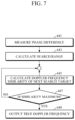
- FIG. 7 is a flowchart illustrating a configuration of a Doppler frequency determination operation according to an embodiment.
- FIG. 8 illustrates a process of obtaining a range-Doppler spectrum by performing range-Doppler processing in a typical TDM FMCW radar apparatus.
- FIG. 9 is a block diagram illustrating a configuration of the TDM FMCW radar apparatus according to an embodiment.
- FIG. 10 is a block diagram of a configuration of a spectrum analyzer according to an embodiment.
- FIG. 11 is a block diagram illustrating a configuration of a Doppler frequency determiner according to an embodiment.
- a frame of a waveform signal transmitted from one transmitting antenna includes at least three consecutive chirps, which have different periods, for each chirp loop.
- a Doppler frequency may be determined from phase difference values between the three consecutive chirps measured from an FMCW radar signal received at a receiving antenna.
- FIG. 4 is a flowchart illustrating a configuration of a signal processing method of a TDM FMCW radar apparatus according to an embodiment.
- the signal processing method of the TDM FMCW radar apparatus includes a wireless transmission operation 410 , a wireless reception operation 420 , a spectrum analysis operation 430 , and a Doppler frequency determination operation 440 .
- the proposed invention describes a case of the TDM FMCW radar apparatus composed of an array of N TX transmitting antennas and N RX receiving antennas.
- the wireless transmission operation 410 is performed at each transmitting antenna
- the wireless reception operation 420 is performed at each receiving antenna
- the spectrum analysis operation 430 and the Doppler frequency determination operation 440 may be performed at all virtual antennas.
- the radar apparatus transmits an FMCW radar waveform signal through the transmitting antenna.
- the FMCW radar waveform signal transmitted by the radar apparatus at least three consecutive chirps have different periods for each chirp loop.
- the expression that three consecutive chirps have different periods includes cases in which two out of three have the same period and the remaining one has a different value, or all three have different values.
- FIG. 6 illustrates a typical frame structure of a radar waveform in the TDM FMCW radar apparatus according to an embodiment.
- a frame is a unit of spectrum analysis, and the number of chirp loops included in one frame is expressed herein as N LOOP .
- FIG. 6 illustrates only two chirp loops as a part of one frame.
- T loop is a length of the chirp loop.
- the chirp loop is a period required for all transmitting antennas to transmit a signal once.
- Each frame is composed of one or more chirp loops, and each of the chirp loops is composed of one or more chirps.
- the number of the chirps per chirp loop is expressed as N TX .
- the number of the chirps per chirp loop is generally equal to the number of transmitting antennas.
- FIG. 6 An upper right end of FIG. 6 illustrates a waveform signal of one chirp period of the radar waveform signal.
- the frequency sweep rate a, the chirp start frequency f 0 , and the sampling delay T ADC are assumed to be the same for all chirps.
- a delay component between a transmitting antenna TX(p) used to transmit the pth chirp and a qth receiving antenna is expressed as ⁇ TX(p),q
- a value of ⁇ TX(p),q is determined by azimuth and elevation of a target, and a relative position of a virtual antenna specified by TX(p) and q from an antenna reference point in space.
- each of chirp loops of an FMCW radar waveform signal transmitted by the radar apparatus to which the signal processing method according to an embodiment is applied includes at least N TX +2 chirps.
- the N TX chirps are valid chirps for estimating a beat frequency and a Doppler frequency, and information that determines the Doppler frequency may be acquired from at least three consecutive chirps from an N TX th chirp.
- the proposed invention is not limited thereto, and the three consecutive chirps in the chirp loop may be positioned at a beginning portion or an intermediate portion of the chirp loop.
- the position or contents of the three consecutive chirps may be different for each FMCW radar waveform signal transmitted by the transmitting antennas.
- the radar apparatus receives an FMCW radar waveform signal reflected by the target using the receiving antenna, demodulates a baseband FMCW radar signal, samples a difference signal between the baseband FMCW radar signal and the transmitted signal, and transforms the sampled signal into a digital signal and outputs the same.
- the radar apparatus determines and outputs a beat frequency and a Doppler frequency from the signal output in the wireless reception operation 420 .
- the N TX transmitting antennas sequentially transmit the FMCW radar waveform signal, and each transmitted FMCW radar waveform signal is reflected by the target and received by the N RX receiving antennas.
- a signal processing circuit of the radar apparatus processes the radar waveform signal for each receiving antenna.
- the signal processing circuit of the radar apparatus processes the waveform signal in units of chirps in the same time slot in the loops received at one receiving antenna.
- the signal processing circuit of the radar apparatus measures phase differences between at least three consecutive chirps having different periods received at the receiving antenna and determines and outputs a true Doppler frequency from measured values and the Doppler frequency output in the spectrum analysis operation. This will be described in detail below.
- the at least three consecutive chirps are configured to differ in at least one of an idle time between the chirps or a ramp time of the chirp. Accordingly, phase components generated due to a Doppler frequency f d may be observed at different time intervals so that more information may be obtained.
- the idle time between the chirps corresponds to T idle
- the ramp time of the chirp corresponds to T ramp .
- the three consecutive chirps in the chirp loop may be configured such that a first chirp differs in ramp time, a last chirp differs in idle time, and an intermediate chirp differs in both ramp time and idle time.
- intermediate chirps may all be configured to differ in both ramp time and idle time.
- positions of the chirps which differ in idle time or ramp time, may be the beginning, intermediate, or end of the loop, and the position or content may be different for each wireless transmitter.
- FIG. 5 is a flowchart illustrating a configuration of the spectrum analysis operation according to an embodiment.
- the spectrum analysis operation may include a range FFT processing operation 431 , a Doppler fast Fourier transform (FFT) processing operation 433 , a range estimation operation 435 , and a Doppler estimation operation 437 .
- FFT Doppler fast Fourier transform
- the signal processing circuit of the radar apparatus transforms the digital signal output in the wireless reception operation 420 into a frequency-domain signal in units of chirps and outputs the same.
- an FFT is selected as an example in the illustrated embodiment, it is understood that the proposed invention encompasses various known transforms for frequency-domain transformation.
- the signal processing circuit of the radar apparatus transforms again the same frequency components of the frequency-domain signal output in the range FFT processing operation 431 into a frequency-domain signal and outputs the same.
- the signal processing circuit of the radar apparatus performs inter-chirp processing by performing FFT after collecting FFT coefficients by frequency, that is, by an FFT index.
- the transformed FFT coefficients are stored in a memory.
- the values stored in the memory are range-Doppler spectrum values obtained through a range FFT and a Doppler FFT.
- the signal processing circuit of the radar apparatus determines and outputs a beat frequency from the signal output in the range FFT processing operation 431 .
- the signal processing circuit of the radar apparatus may search for a position of a peak in the spectrum output in the range FFT processing operation 431 , that is, an index storing a maximum value, to identify a beat frequency, and calculate a range to the target using the beat frequency.
- the signal processing circuit of the radar apparatus determines and outputs a Doppler frequency from the signal output and stored in the Doppler FFT processing operation 433 .
- the signal processing circuit of the radar apparatus may determine the Doppler frequency by identifying a position of an array that stores a peak value in the range-Doppler spectrum.
- a true value of the Doppler frequency may be determined from a phase difference between the chirps measured from at least three consecutive chirp signals having a period different from a measured value.
- a Doppler frequency of the aliased spectrum, at which a theoretically calculated phase difference has the most similar value to the measured phase difference may be determined as a true Doppler frequency.
- the true Doppler frequency is spaced apart from the measured Doppler frequency by an integer multiple of a width of the aliased spectrum.
- the phase difference of the at least three consecutive chirp signals having different periods is calculated from the Doppler frequency of the aliased spectrum that may be a candidate, and the Doppler frequency whose phase difference is most similar to the actually measured phase difference may be estimated as the true Doppler frequency.
- FIG. 8 illustrates a process of obtaining a range-Doppler spectrum by performing range-Doppler processing in a typical TDM FMCW radar apparatus. Even in the proposed invention, range-Doppler processing is performed in a manner similar to that shown in FIG. 2 , and description is made with reference to the qth receiving antenna as an example.
- a signal processing procedure as illustrated in FIG. 2 is performed at each receiving channel for all TX(p)
- a total of N TX range-Doppler spectra may be obtained as shown in FIG. 8 . As indicated by gray in FIG.
- Equation 4 the phase differences between the consecutive chirps are determined by an idle time T idle and a ramp Time T ramp .
- T idle idle time
- T ramp ramp Time
- Equation 5 k is an arbitrary integer and k is estimated to determine the actual Doppler frequency f d,true .
- FIG. 7 is a flowchart illustrating a configuration of the Doppler frequency determination operation according to an embodiment.
- the Doppler frequency determination operation may include a phase difference measurement operation 441 , a search range calculation operation 443 , and Doppler-frequencies-with-maximum-similarity search operations 445 , 447 , and 449 .
- phase difference measurement operation 441 the signal processing circuit of the radar apparatus measures phase differences between at least three consecutive chirp signals having different periods included in the chirp loop. These phase difference values may be measured by detecting a start point and an end point of each of the chirps and measuring a time difference between the end points of the consecutive chirps. A measurement vector as shown below may be generated from the measured phase differences by using the phase differences between the chirps obtained in Equation 4,
- the signal processing circuit of the radar apparatus determines a search range of the Doppler frequency of the aliased spectrum by a ratio of a maximum Doppler frequency of the target to be detected and a maximum Doppler frequency obtained from the range-Doppler spectrum.
- Equation 5 a value of k may be referred to as an index of the Doppler frequencies present on the aliased spectrum.
- index of the Doppler frequencies present on the aliased spectrum There are countless aliased spectra, and thus, appropriately limiting the range thereof is important in terms of the possibility that the proposed invention may be actually applied.
- the maximum Doppler frequency of the target may be expressed as follows,
- Equation 4 a minimum measurable time difference is ⁇ T ramp + ⁇ T idle .
- At least three consecutive chirps are configured such that the sum of ⁇ T ramp and ⁇ T idle , that is, an inter-chirp difference value of the idle time and an inter-chirp difference value of the ramp time is limited by a maximum moving velocity of the target.
- ⁇ T ramp and ⁇ T idle are appropriately adjusted to satisfy the relationship of Equation 8.
- Equation 5 a peak due to the aliasing phenomenon occurs at intervals of 2f d,max on the Doppler spectrum.
- an integer which is greater than or equal to a ratio of Equations 7 and 2f d,max but is smallest, is determined as the maximum value of k.
- 2f d,max,target is the maximum Doppler frequency to be detected
- 2f d,max is the maximum Doppler frequency that may be measured through the Doppler processing, that is, a Doppler FFT. That is, k that maximizes Re ⁇ w(k) H x ⁇ is identified while changing k from ⁇ k MAX to k MAX within a range of 2f d,max,target from a Doppler frequency of 2f d,measured , which is primarily measured through the Doppler processing. (H: Hermitian)
- the signal processing circuit of the radar apparatus determines and outputs the Doppler frequency, at which a theoretically calculated phase difference is most similar to the measured phase difference, among the Doppler frequencies of the aliased spectrum.
- a phase difference between at least three consecutive chirp signals having different periods included in the chirp loop is theoretically calculated, and a similarity value between the theoretically calculated value and the measured value measured in the phase difference measurement operation 441 is calculated (operation 445 ).
- the Doppler frequency with the maximum value among the calculated similarity values is retrieved ( 447 ), and the retrieved Doppler frequency is output as the true Doppler frequency ( 449 ).
- Equation 5 Since k, which has the highest degree of similarity between the theoretical value of Equation 10 and the measured value of Equation 6, is the solution, k that maximizes Re ⁇ w(k) H x ⁇ is identified by changing k within an appropriate range, and the actual Doppler frequency is calculated by substituting the estimation result into Equation 5.
- a frame of a waveform signal transmitted from one transmitting antenna includes at least three consecutive chirps, which have different periods, for each chirp loop.
- a Doppler frequency may be determined from phase difference values between the three consecutive chirps measured from an FMCW radar signal received at a receiving antenna.
- FIG. 9 is a block diagram illustrating a configuration of the TDM FMCW radar apparatus according to an embodiment.
- the TDM FMCW radar apparatus includes a wireless transmitter 610 , a wireless receiver 630 , a spectrum analyzer 650 , and a Doppler frequency determiner 670 .
- N TX wireless transmitters, N RX wireless receivers, and N TX *N RX spectrum analyzers are included. That is, since the spectrum analyzer must be provided for each virtual antenna, the N TX spectrum analyzers are connected to each wireless receiver.
- the wireless transmitter 610 transmits an FMCW radar waveform signal through a transmitting antenna.
- the FMCW radar waveform signal transmitted by the wireless transmitter 610 at least three consecutive chirps have different periods for each chirp loop.
- the expression that three consecutive chirps have different periods includes cases in which two out of three have the same period and the remaining one has a different value, or all three have different values.
- the chirp loop of the FMCW radar waveform signal transmitted by the wireless transmitter 610 includes at least N TX +2 chirps.
- the N TX chirps are valid chirps for estimating a beat frequency and a Doppler frequency, and information that determines the Doppler frequency may be acquired from at least three consecutive chirps from an N TX th chirp.
- the proposed invention is not limited thereto, and the three consecutive chirps in the chirp loop may be positioned at a beginning portion or an intermediate portion of the chirp loop.
- the position or contents of the three consecutive chirps may be different for each FMCW radar waveform signal transmitted by the transmitting antennas.
- the wireless receiver 630 receives an FMCW radar waveform signal reflected by the target using a receiving antenna, demodulates a baseband FMCW radar signal, samples a difference signal between the baseband FMCW radar signal and the transmitted signal, and transforms the sampled signal into a digital signal and outputs the same.
- the transmitting antennas and the receiving antennas are generally linearly arranged at equal intervals, but may also be non-linearly arranged at non-uniform intervals.
- the spectrum analyzer 650 determines and outputs a beat frequency and a Doppler frequency from the signal output from the wireless receiver 630 .
- the N TX transmitting antennas sequentially transmit the FMCW radar waveform signal, and each transmitted FMCW radar waveform signal is reflected by the target and received by the N RX wireless receivers.
- Each spectrum analyzer 650 processes the chirps of a period corresponding to the wireless transmitter 610 allocated thereto among the chirps output from the wireless receiver 630 .
- the spectrum analyzer 650 - 1 may be allocated to process first chirps of the N TX chirps that are repeated for each chirp loop, and the spectrum analyzer 650 - 2 may be allocated to process second chirps of the N TX chirps that are repeated for each chirp loop.
- the Doppler frequency determiner 670 measures values of phase differences between at least three consecutive chirps having different periods received by the wireless receiver 630 and determines and outputs a true Doppler frequency from the measured values and the Doppler frequency output in the spectrum analysis operation. This will be described in detail below.
- the at least three consecutive chirps are configured to differ in at least one of an idle time between the chirps or a ramp time of the chirp. Accordingly, phase components generated due to a Doppler frequency f d may be observed at different time intervals so that more information may be obtained.
- the idle time between the chirps corresponds to T idle
- the ramp time of the chirp corresponds to T ramp .
- the three consecutive chirps having different periods may be configured such that a first chirp differs in ramp time, a last chirp differs in idle time, and an intermediate chirp differs in both ramp time and idle time.
- intermediate chirps may all be configured to differ in both ramp time and idle time.
- positions of the chirps which differ in idle time or ramp time, may be the beginning, intermediate, or end of the loop, and the position or content may be different for each wireless transmitter.
- FIG. 10 is a block diagram of a configuration of the spectrum analyzer according to an embodiment.
- the spectrum analyzer 650 includes a range FFT processor 651 , a range estimator 652 , a Doppler FFT processor 655 , and a Doppler estimator 654 .
- the range FFT processor 651 transforms the digital signal output from the wireless receiver 630 into a frequency-domain signal in units of chirps and outputs the same. Although an FFT is selected as an example in the illustrated embodiment, it is understood that the proposed invention encompasses various known transforms for frequency-domain transformation.
- the range FFT processor 651 performs FFT on a beat frequency signal of the chirp transmitted by the antenna allocated thereto among the chirps, which are present in a first chirp loop of the digital signal output by the wireless receiver 630 connected thereto, and stores the transformed signal in a range FFT buffer 653 , and performs FFT on a beat frequency signal of the chirp, which is transmitted by the same antenna, in the next chirp loop and stores the transformed signal in the range FFT buffer 653 .
- the range FFT processor 651 processes the FFT by as many times as the number of chirp loops, that is, N LOOP times, and the range FFT buffer 653 has a size capable of storing at least N LOOP FFT coefficient sets.
- the embodiment illustrated in FIG. 10 adopts a structure in which one range FFT processor 651 is provided for each virtual antenna, and performs FFT on the beat frequency signal from the signal, which is received by the receiving antenna, for each chirp loop, and outputs a result, and the result is accumulated and stored in the range FFT buffer 653 . Accordingly, the range FFT processor 651 should have a speed at which a single Fourier operation may be fully processed within a period of at least one chirp loop.
- the range estimator 652 determines and outputs a beat frequency from the signal output from the range FFT processor 651 .
- the range estimator 652 may search for a position of a peak, that is, an index storing the maximum value in the spectrum stored in the range FFT buffer 653 , to identify the beat frequency, and calculate a range to the target from the beat frequency.
- the Doppler FFT processor 655 transforms the same frequency components of the frequency-domain signal output from the range FFT processor 651 into a frequency-domain signal again and outputs the same.
- the Doppler FFT processor 655 performs inter-chirp processing by performing FFT after collecting FFT coefficients, which are stored in the range FFT buffer 653 , by frequency, that is, by an FFT index.
- the transformed FFT coefficients are stored in a Doppler FFT buffer 657 .
- the Doppler FFT processor 655 includes as many FFT transformers as the number of Fourier coefficients stored in the range FFT buffer 653 .
- a structure of repeatedly executing one Fourier transformer may be employed.
- the Doppler FFT processor 655 receives N LOOP output coefficients of the same frequency corresponding to the number N LOOP of the chirp loops, performs FFT on the output coefficients, and stores the transformed output coefficients in the Doppler FFT buffer 657 .
- the values stored in the Doppler FFT buffer 657 are range-Doppler spectrum values obtained through a range FFT and a Doppler FFT.
- the Doppler estimator 654 determines and outputs a Doppler frequency from the signal output from the Doppler FFT processor 655 .
- the Doppler estimator 654 may determine the Doppler frequency by identifying a position of an array that stores a peak value from the range-Doppler spectrum stored in the Doppler FFT buffer 657
- a true value of the Doppler frequency may be determined from a phase difference between the chirps measured from at least three consecutive chirp signals having a period different from a measured value.
- a Doppler frequency of the aliased spectrum, at which a theoretically calculated phase difference has the most similar value to the measured phase difference may be determined as a true Doppler frequency.
- the Doppler frequency determiner 670 may measure a phase difference between the chirps from the three consecutive chirp signals output from the wireless receiver 630 in FIG. 6 , receive the plurality of Doppler frequencies calculated by the Doppler estimator 654 , and determine and output the Doppler frequency, at which a measured phase difference is closest to a theoretically calculated value, from among the plurality of Doppler frequencies, as a true value. Since these have been previously described with reference to FIG. 8 , detailed descriptions thereof will be omitted.
- FIG. 11 is a block diagram illustrating a configuration of the Doppler frequency determiner according to an embodiment.
- the Doppler frequency determiner includes a phase difference measurer 671 , a search range calculator 673 , and a Doppler frequency searcher 675 .
- the phase difference measurer 671 measures the phase difference expressed by Equation 4, that is, the phase difference between the three consecutive chirps. These phase difference values may be measured by detecting a start point and an end point of each of the chirps and measuring a time difference between the end points of the consecutive chirps.
- the search range calculator 673 determines a search range of the Doppler frequency of the aliased spectrum by a ratio of the maximum Doppler frequency of the target to be detected and the maximum Doppler frequency obtained from the range-Doppler spectrum.
- the Doppler frequency searcher 675 determines and outputs the Doppler frequency, at which a theoretically calculated phase difference value is most similar to a measured phase difference value, from among the Doppler frequencies of the aliased spectrum corresponding to the search range calculated by the search range calculator 673 .
- a phase difference between at least three consecutive chirp signals having different periods included in the chirp loop is theoretically calculated, and a similarity value between the theoretically calculated value and the measured value measured by the phase difference measurer 671 is calculated.
- the Doppler frequency with the maximum value among the calculated similarity values is retrieved and output as the true Doppler frequency.
- FIG. 11 The operation of the configuration of FIG. 11 has been described in the method invention described with reference to FIG. 7 , and thus detailed description thereof will be omitted.
- the proposed invention it is possible to overcome the existing limit of a detectable radial speed of a target in a TDM FMCW radar apparatus. Furthermore, according to the proposed invention, it is possible to increase a position resolution by increasing the number of transmitting antennas in a TDM FMCW radar apparatus. Furthermore, it is possible to solve a Doppler ambiguity problem while minimizing constraints in an antenna design in a TDM FMCW radar apparatus. Alternatively, according to the proposed invention, it is possible to solve a Doppler ambiguity problem without increasing a frame length in a TDM FMCW radar apparatus.
Landscapes
- Engineering & Computer Science (AREA)
- Radar, Positioning & Navigation (AREA)
- Remote Sensing (AREA)
- Computer Networks & Wireless Communication (AREA)
- Physics & Mathematics (AREA)
- General Physics & Mathematics (AREA)
- Radar Systems Or Details Thereof (AREA)
Abstract
Description
|2πf d T loop|<π. [Equation 1]
-
- α: frequency sweep rate
- Tidle,p: idle time of pth chirp
- Tramp,p: length of frequency change section of pth chirp
- Tchirp,p: chirp period of the pth chirp(=Tidle,p+Tramp,p)
- TADC: sampling delay that is a time difference between time at which transmission of a chirp starts and time at which sampling starts
- f0: chirp start frequency.
∅p,q=2π(f 0 +αT ADC)τTX(p),q+2πf d(Σi=0 p-1 T chirp,i +T idle,p). [Equation 3]
-
- when a relationship of τTX(p),q=τTX(p+1),q=τTX(p+2),q is satisfied,
- phase differences between consecutive chirps may be expressed as follows,
f d,true =f d,measured+2kf d,max. [Equation 5]
(where, c is a wave velocity).
Claims (12)
Applications Claiming Priority (2)
| Application Number | Priority Date | Filing Date | Title |
|---|---|---|---|
| KR1020210117236A KR102832648B1 (en) | 2021-09-02 | 2021-09-02 | TDM FMCW Radar Apparatus and Signal Processing Method for the Apparatus |
| KR10-2021-0117236 | 2021-09-02 |
Publications (2)
| Publication Number | Publication Date |
|---|---|
| US20230066386A1 US20230066386A1 (en) | 2023-03-02 |
| US12222441B2 true US12222441B2 (en) | 2025-02-11 |
Family
ID=85285494
Family Applications (1)
| Application Number | Title | Priority Date | Filing Date |
|---|---|---|---|
| US17/584,348 Active 2043-03-10 US12222441B2 (en) | 2021-09-02 | 2022-01-25 | TDM FMCW radar apparatus and signal processing method of apparatus |
Country Status (3)
| Country | Link |
|---|---|
| US (1) | US12222441B2 (en) |
| KR (1) | KR102832648B1 (en) |
| CN (1) | CN115754950A (en) |
Families Citing this family (9)
| Publication number | Priority date | Publication date | Assignee | Title |
|---|---|---|---|---|
| US12235341B2 (en) * | 2021-12-06 | 2025-02-25 | Microsoft Technology Licensing, Llc | Radar tracking with greater than range resolution precision |
| US12099110B2 (en) | 2022-04-19 | 2024-09-24 | Infineon Technologies Ag | Radar system and method for performing direction of arrival estimation |
| US12228679B2 (en) | 2022-04-27 | 2025-02-18 | Infineon Technologies Ag | Radar system and method for performing velocity estimation |
| US12189053B2 (en) * | 2022-04-27 | 2025-01-07 | Infineon Technologies Ag | Radar system and method for performing range estimation |
| CN116679292B (en) * | 2023-06-09 | 2025-11-14 | 惠州市德赛西威汽车电子股份有限公司 | A radar, a radar channel separation method and apparatus |
| CN119986574A (en) * | 2023-11-01 | 2025-05-13 | 加特兰微电子科技(上海)有限公司 | Signal processing method, storage medium, radar chip and integrated circuit |
| CN117519474B (en) * | 2023-11-06 | 2024-05-14 | 中国人民解放军陆军工程大学 | A radar gesture feature acquisition method considering motion prior |
| CN120224245A (en) * | 2023-12-26 | 2025-06-27 | 维沃移动通信有限公司 | Measurement method, signal transmission method, device and equipment |
| CN120981734A (en) * | 2024-01-22 | 2025-11-18 | 深圳引望智能技术有限公司 | Signal transmission methods and devices, signal processing methods and devices, and radar systems |
Citations (15)
| Publication number | Priority date | Publication date | Assignee | Title |
|---|---|---|---|---|
| US20140253365A1 (en) | 2013-01-14 | 2014-09-11 | Robert Bosch Gmbh | Method for cyclically measuring distances and velocities of objects using an fmcw radar sensor |
| US20160131752A1 (en) * | 2014-11-11 | 2016-05-12 | Nxp, B.V. | Mimo radar system |
| US20170219689A1 (en) * | 2016-04-15 | 2017-08-03 | Mediatek Inc. | Radar Interference Mitigation Method And Apparatus |
| US9784828B2 (en) * | 2014-08-27 | 2017-10-10 | Texas Insturments Incorporated | FMCW doppler processing algorithm for achieving CW performance |
| US20180175898A1 (en) * | 2016-12-20 | 2018-06-21 | Infineon Technologies Ag | Rf transceiver with test capability |
| US20190154439A1 (en) * | 2016-03-04 | 2019-05-23 | May Patents Ltd. | A Method and Apparatus for Cooperative Usage of Multiple Distance Meters |
| US20190339376A1 (en) * | 2018-05-04 | 2019-11-07 | GM Global Technology Operations LLC | Differential phase-based detector |
| US20200241125A1 (en) * | 2019-01-28 | 2020-07-30 | Steradian Semiconductors Private Limited | Method, Apparatus and Device for Determining a Velocity of an Object in a Time Switched MIMO Radar System |
| US20210181330A1 (en) * | 2019-12-13 | 2021-06-17 | Oculii Corp. | Systems and methods for virtual doppler and/or aperture enhancement |
| US20210255303A1 (en) * | 2020-02-13 | 2021-08-19 | Nxp B.V. | Radar apparatuses and methods involving determination of velocity of an object |
| US11366211B2 (en) * | 2016-12-15 | 2022-06-21 | Texas Instruments Incorporated | Maximum measurable velocity in frequency modulated continuous wave (FMCW) radar |
| US20220334240A1 (en) * | 2021-04-19 | 2022-10-20 | Nxp B.V. | Radar communications with disparate pulse repetition intervals |
| US11513187B2 (en) * | 2018-05-07 | 2022-11-29 | Arbe Robotics Ltd. | FMCW automotive radar incorporating modified slow time processing of fine range-doppler data |
| US11693107B2 (en) * | 2020-09-29 | 2023-07-04 | Steradian Semiconductors Private Limited | System, device and method for efficient MIMO radar |
| US11740345B2 (en) * | 2019-03-06 | 2023-08-29 | Texas Instruments Incorporated | Dithering FMCW radar parameters to mitigate spurious signals |
Family Cites Families (3)
| Publication number | Priority date | Publication date | Assignee | Title |
|---|---|---|---|---|
| KR102144668B1 (en) * | 2013-11-05 | 2020-08-14 | 현대모비스 주식회사 | Vechicle radar for discriminating false target using variable wave and method for discriminating false target using it |
| JP6945332B2 (en) | 2017-04-20 | 2021-10-06 | 株式会社デンソーテン | Radar device and target detection method |
| JP7437649B2 (en) | 2019-11-18 | 2024-02-26 | パナソニックIpマネジメント株式会社 | radar equipment |
-
2021
- 2021-09-02 KR KR1020210117236A patent/KR102832648B1/en active Active
-
2022
- 2022-01-25 US US17/584,348 patent/US12222441B2/en active Active
- 2022-02-07 CN CN202210116853.6A patent/CN115754950A/en active Pending
Patent Citations (15)
| Publication number | Priority date | Publication date | Assignee | Title |
|---|---|---|---|---|
| US20140253365A1 (en) | 2013-01-14 | 2014-09-11 | Robert Bosch Gmbh | Method for cyclically measuring distances and velocities of objects using an fmcw radar sensor |
| US9784828B2 (en) * | 2014-08-27 | 2017-10-10 | Texas Insturments Incorporated | FMCW doppler processing algorithm for achieving CW performance |
| US20160131752A1 (en) * | 2014-11-11 | 2016-05-12 | Nxp, B.V. | Mimo radar system |
| US20190154439A1 (en) * | 2016-03-04 | 2019-05-23 | May Patents Ltd. | A Method and Apparatus for Cooperative Usage of Multiple Distance Meters |
| US20170219689A1 (en) * | 2016-04-15 | 2017-08-03 | Mediatek Inc. | Radar Interference Mitigation Method And Apparatus |
| US11366211B2 (en) * | 2016-12-15 | 2022-06-21 | Texas Instruments Incorporated | Maximum measurable velocity in frequency modulated continuous wave (FMCW) radar |
| US20180175898A1 (en) * | 2016-12-20 | 2018-06-21 | Infineon Technologies Ag | Rf transceiver with test capability |
| US20190339376A1 (en) * | 2018-05-04 | 2019-11-07 | GM Global Technology Operations LLC | Differential phase-based detector |
| US11513187B2 (en) * | 2018-05-07 | 2022-11-29 | Arbe Robotics Ltd. | FMCW automotive radar incorporating modified slow time processing of fine range-doppler data |
| US20200241125A1 (en) * | 2019-01-28 | 2020-07-30 | Steradian Semiconductors Private Limited | Method, Apparatus and Device for Determining a Velocity of an Object in a Time Switched MIMO Radar System |
| US11740345B2 (en) * | 2019-03-06 | 2023-08-29 | Texas Instruments Incorporated | Dithering FMCW radar parameters to mitigate spurious signals |
| US20210181330A1 (en) * | 2019-12-13 | 2021-06-17 | Oculii Corp. | Systems and methods for virtual doppler and/or aperture enhancement |
| US20210255303A1 (en) * | 2020-02-13 | 2021-08-19 | Nxp B.V. | Radar apparatuses and methods involving determination of velocity of an object |
| US11693107B2 (en) * | 2020-09-29 | 2023-07-04 | Steradian Semiconductors Private Limited | System, device and method for efficient MIMO radar |
| US20220334240A1 (en) * | 2021-04-19 | 2022-10-20 | Nxp B.V. | Radar communications with disparate pulse repetition intervals |
Non-Patent Citations (5)
| Title |
|---|
| Matthieas Kronauge and Hermann Rohling, "New chirp sequence radar waveform", IEEE Transactions on Aerospace and Electronic Systems 50.4 (2014); 2870-2877. |
| Roos, Fabian, et al. "Enhancement of Doppler Unambiguity for Chirp Sequence Modulated TDM MIMO Radars", 2018 IEEE MTT-S International Conference on Microwaves for Intelligent Mobility (ICMIM), IEEE, 2018. |
| Schmid, Christian M., et al., "Motion compensation and efficient array design for TDMAN FMCW MIMO radar systems", 2012 6th European conference on Antennas and Propagation (EUCAP), IEEE, 2012. |
| Sun, Shunqiao, et al., "MIMO radar for advanced driver-assistance systems and autonomous driving: Advantages and challenges." IEEE Signal Processing Magazine. 2020. |
| Wojtkiewicz, Andrzej, et al. "Two-dimensional signal processing in FMCW radars", Proc. XXKKTOiUE (1997). 475-480. |
Also Published As
| Publication number | Publication date |
|---|---|
| KR102832648B1 (en) | 2025-07-10 |
| CN115754950A (en) | 2023-03-07 |
| US20230066386A1 (en) | 2023-03-02 |
| KR20230034082A (en) | 2023-03-09 |
Similar Documents
| Publication | Publication Date | Title |
|---|---|---|
| US12222441B2 (en) | TDM FMCW radar apparatus and signal processing method of apparatus | |
| EP3640675B1 (en) | Estimating angle of a human target using millimeter-wave radar | |
| CN111157981B (en) | MIMO FMCW radar system | |
| EP4191279A1 (en) | Tdm fmcw radar apparatus and signal processing method of apparatus | |
| JP6035165B2 (en) | Radar equipment | |
| EP3021132B1 (en) | Mimo radar system | |
| EP1970728B1 (en) | DSSS radar, method implemented by radar and computer-readable storage medium | |
| US20120313810A1 (en) | Radar apparatus and method | |
| CN101349752A (en) | Device and method for estimating the number of arrival signals | |
| US12270939B2 (en) | Radar device | |
| JP2009025159A (en) | Radar equipment | |
| US12313768B2 (en) | Signal processing method and apparatus | |
| US9568601B1 (en) | Successive-MFCW modulation for ultra-fast narrowband radar | |
| JP4769596B2 (en) | Electronic scanning radar equipment | |
| US20190025419A1 (en) | Moving object detection system and moving object detection method | |
| JP2010175457A (en) | Radar apparatus | |
| JP6567226B2 (en) | Radar equipment | |
| US20250035767A1 (en) | Positioning system and vehicle including positioning system, and positioning method | |
| Rahayu et al. | Compressive signal processing for estimating range-velocity-AoA in FMCW radar applications | |
| CN117092634A (en) | Radar speed measurement defuzzification method, device and storage medium | |
| US12332337B2 (en) | Radar velocity measurement system and method and radar device thereof | |
| HIDAYAT et al. | Compressive Signal Processing for Estimating Range-Velocity-AoA in FMCW Radar Applications | |
| Inaba | Multiple target detection for stepped multiple‐frequency interrupted CW radar | |
| CN115616499A (en) | Radar apparatus and signal processing method thereof |
Legal Events
| Date | Code | Title | Description |
|---|---|---|---|
| AS | Assignment |
Owner name: SMART RADAR SYSTEM, INC., KOREA, REPUBLIC OF Free format text: ASSIGNMENT OF ASSIGNORS INTEREST;ASSIGNORS:KIM, YONG JAE;CHOI, JEONG MIN;REEL/FRAME:058766/0608 Effective date: 20220112 |
|
| FEPP | Fee payment procedure |
Free format text: ENTITY STATUS SET TO UNDISCOUNTED (ORIGINAL EVENT CODE: BIG.); ENTITY STATUS OF PATENT OWNER: SMALL ENTITY |
|
| FEPP | Fee payment procedure |
Free format text: ENTITY STATUS SET TO SMALL (ORIGINAL EVENT CODE: SMAL); ENTITY STATUS OF PATENT OWNER: SMALL ENTITY |
|
| STPP | Information on status: patent application and granting procedure in general |
Free format text: DOCKETED NEW CASE - READY FOR EXAMINATION |
|
| STPP | Information on status: patent application and granting procedure in general |
Free format text: NON FINAL ACTION MAILED |
|
| STPP | Information on status: patent application and granting procedure in general |
Free format text: RESPONSE TO NON-FINAL OFFICE ACTION ENTERED AND FORWARDED TO EXAMINER |
|
| STPP | Information on status: patent application and granting procedure in general |
Free format text: NOTICE OF ALLOWANCE MAILED -- APPLICATION RECEIVED IN OFFICE OF PUBLICATIONS |
|
| ZAAB | Notice of allowance mailed |
Free format text: ORIGINAL CODE: MN/=. |
|
| STPP | Information on status: patent application and granting procedure in general |
Free format text: PUBLICATIONS -- ISSUE FEE PAYMENT RECEIVED |
|
| STPP | Information on status: patent application and granting procedure in general |
Free format text: PUBLICATIONS -- ISSUE FEE PAYMENT VERIFIED |
|
| STCF | Information on status: patent grant |
Free format text: PATENTED CASE |