US12222185B1 - Reverse pressure grip for firearms - Google Patents
Reverse pressure grip for firearms Download PDFInfo
- Publication number
- US12222185B1 US12222185B1 US18/234,459 US202318234459A US12222185B1 US 12222185 B1 US12222185 B1 US 12222185B1 US 202318234459 A US202318234459 A US 202318234459A US 12222185 B1 US12222185 B1 US 12222185B1
- Authority
- US
- United States
- Prior art keywords
- panel
- grip
- reverse pressure
- pressure mechanism
- gun
- Prior art date
- Legal status (The legal status is an assumption and is not a legal conclusion. Google has not performed a legal analysis and makes no representation as to the accuracy of the status listed.)
- Active
Links
Images


Classifications
-
- F—MECHANICAL ENGINEERING; LIGHTING; HEATING; WEAPONS; BLASTING
- F41—WEAPONS
- F41C—SMALLARMS, e.g. PISTOLS, RIFLES; ACCESSORIES THEREFOR
- F41C23/00—Butts; Butt plates; Stocks
- F41C23/16—Forestocks; Handgrips; Hand guards
-
- F—MECHANICAL ENGINEERING; LIGHTING; HEATING; WEAPONS; BLASTING
- F41—WEAPONS
- F41C—SMALLARMS, e.g. PISTOLS, RIFLES; ACCESSORIES THEREFOR
- F41C23/00—Butts; Butt plates; Stocks
- F41C23/10—Stocks or grips for pistols, e.g. revolvers
-
- F—MECHANICAL ENGINEERING; LIGHTING; HEATING; WEAPONS; BLASTING
- F41—WEAPONS
- F41C—SMALLARMS, e.g. PISTOLS, RIFLES; ACCESSORIES THEREFOR
- F41C27/00—Accessories; Details or attachments not otherwise provided for
- F41C27/22—Balancing or stabilising arrangements on the gun itself, e.g. balancing weights
Definitions
- the present invention relates generally to the field of firearm grips, and more specifically to firearm grips containing spring mechanisms.
- the rigid front face of the gun grip is replaced with a sliding grip panel, which inserts into a conjugate panel recess in the gun grip.
- the panel recess contains multiple coiled compression springs, which extend between the interior forward end of the grip panel and the rear surface of the panel recess.
- the compression of the springs under the inward constrictive force of a shooter's hand on the gun grip, produces an opposing outward expansive force, which changes in response to the degree of insertion of the grip panel into the panel recess.
- the outward expansive force exerted by the compression springs is adjustable by removing or adding to the number of springs or substituting springs with higher or lower spring constants.
- the reactive force of the compression springs be uniform across the length of the grip panel. This requires a uniform spring constant for all springs and uniform spring spacing on the rear surface of the panel recess.
- the outer surface of the grip panel preferably has indentations for proper positioning of the shooter's fingers.
- the reverse pressure grip enables a stabilizing balance of forces on the gun grip with less constricting force from the shooter's hand, the shooter will experience less grip fatigue and will consequently be able to maintain aiming accuracy over a longer time period. Also, the reverse pressure grip allows shooters having below average grip strength to still maintain aiming stability using less force than would be required by conventional grips.
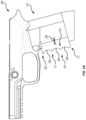
- FIG. 1 A is a perspective view of a gun grip frame having a gun grip incorporating an embodiment of the present invention
- FIG. 1 B is the perspective view of a gun grip frame having a gun grip incorporating an embodiment of the present invention, with the grip panel removed to expose the compression springs;
- FIG. 2 A is a side profile view of a gun grip frame having a gun grip incorporating an embodiment of the present invention
- FIG. 2 B is a top plan view of a gun grip frame having a gun grip incorporating an embodiment of the present invention
- FIG. 2 C is a rear profile view of a gun grip frame having a gun grip incorporating an embodiment of the present invention
- FIG. 3 A is a side cut-away view of a gun grip frame having a gun grip incorporating an embodiment of the present invention.
- FIG. 3 B is a detail view of the area enclosed by circle “A” in FIG. 3 A .
- oblong grip panel 11 has a generally arcuate-rectangular lateral cross section, with a generally arcuate closed front panel end 12 and a generally rectangular open inner panel end 13 .
- the inner panel end 13 is configured to insert, along a sliding rail mechanism 25 , through an insertion width 20 into a conjugate panel recess 14 in the gun grip 31 .
- Multiple steel coiled compression springs 15 within the panel recess 14 are configured to resist the sliding insertion of the grip panel 11 into the panel recess 14 through the insertion width 20 (best seen in FIGS. 2 A and 3 B ).
- the proximal end 16 of each compression spring 15 engages the interior surface 18 of the forward panel end 12
- the distal end 17 of each spring 15 engages the rear inner surface 19 of the panel recess 14 .
- This configuration caused the springs 15 to compress when an inward constricting force 22 is applied to the forward panel end 12 of the grip panel 11 , such that the compressed springs 15 (best seen in FIGS. 3 A and 3 B ) exert an outward expansion force 21 which balances the inward constricting force 22 , thereby stabilizing the gun grip 31 with less gripping force 22 than would otherwise be required.
- the compression springs 15 are uniformly spaced along the rear inner surface 19 of the panel recess 14 , so as to provide a uniform outward expansive force 21 .
- finger grip indentations 24 are provided on the exterior surface 23 of the front panel end 12 of the grip panel 11 .
Landscapes
- Engineering & Computer Science (AREA)
- General Engineering & Computer Science (AREA)
- Toys (AREA)
Abstract
In a firearm gun grip, the rigid front force of the gun grip is replaced with a sliding grip panel, which inserts into a conjugate panel recess in the gun grip. The panel recess contains multiple coiled compression springs, which extend between the interior forward end of the grip panel and the rear surface of the panel recess. The compression of the springs, under the inward constrictive force of a shooter's hand on the gun grip, produces an opposing outward expansive force, which changes in response to the degree of insertion of the grip panel into the panel recess, thereby serving to stabilize the gun grip and improve aiming accuracy.
Description
The present invention relates generally to the field of firearm grips, and more specifically to firearm grips containing spring mechanisms.
In maintaining the aiming stability of a firearm, it is important to balance the opposing forces of the shooter's hand squeezing the gun grip and the reactive force of the grip back against the hand. The stronger and more uniform the shooter's grip, the more sustained is the balance of forces through the firing cycle, thereby providing greater stability of the firearm and optimal aiming accuracy.
Conventional firearm grips, however, are too rigid to allow for much of a range in the maximum reactive force they can apply against a shooter's grip, so that it's difficult to achieve a sustained balance of forces for shooters having different grip strengths. The present invention addresses this shortcoming by providing an adjustable reactive force supplied by multiple steel coil compressive springs in a sliding panel of the gun grip.
In the present invention, the rigid front face of the gun grip is replaced with a sliding grip panel, which inserts into a conjugate panel recess in the gun grip. The panel recess contains multiple coiled compression springs, which extend between the interior forward end of the grip panel and the rear surface of the panel recess. The compression of the springs, under the inward constrictive force of a shooter's hand on the gun grip, produces an opposing outward expansive force, which changes in response to the degree of insertion of the grip panel into the panel recess. The relationship between the width of the grip panel insertion “x” and the springs' reactive force “F” is given by Hooke's Law as follows:
F=Kx
where K is the sum total of the spring constants of the multiple compression springs.
F=Kx
where K is the sum total of the spring constants of the multiple compression springs.
For example, if the sliding grip panel's insertion width is 15 millimeters, and there are three compression springs, each having a spring constant K of 8 Newtons/millimeter, the balancing reactive force exerted upon the grip panel by the springs would be:
F=Kx=15 mm×24 N/mm=360 N=81 lbs. force
F=Kx=15 mm×24 N/mm=360 N=81 lbs. force
Since typical shooter's grip forces fall in the range of 40-80 lbs. (178-356 N), a three-spring version of the present invention's reverse pressure mechanism, having a grip panel insertion width in the range of 5-15 mm (0.2-0.6 in.), would require a total spring constant K in the range:
K min =F/x=178 N/15 mm=12 N/mm
K max =F/x=356 N/15 mm=24 N/mm
so that the range of individual spring constants would be 4-8 N/mm.
K min =F/x=178 N/15 mm=12 N/mm
K max =F/x=356 N/15 mm=24 N/mm
so that the range of individual spring constants would be 4-8 N/mm.
In one embodiment of the present invention, the outward expansive force exerted by the compression springs is adjustable by removing or adding to the number of springs or substituting springs with higher or lower spring constants.
In order to maintain the proper balance of forces on the grip panel, it's important that the reactive force of the compression springs be uniform across the length of the grip panel. This requires a uniform spring constant for all springs and uniform spring spacing on the rear surface of the panel recess. In order to insure uniformity in the shooter's constricting force on the gun grip, the outer surface of the grip panel preferably has indentations for proper positioning of the shooter's fingers.
Since the reverse pressure grip enables a stabilizing balance of forces on the gun grip with less constricting force from the shooter's hand, the shooter will experience less grip fatigue and will consequently be able to maintain aiming accuracy over a longer time period. Also, the reverse pressure grip allows shooters having below average grip strength to still maintain aiming stability using less force than would be required by conventional grips.
The foregoing summarizes the general design features of the present invention. In the following sections, specific embodiments of the present invention will be described in some detail. These specific embodiments are intended to demonstrate the feasibility of implementing the present invention in accordance with the general design features discussed above. Therefore, the detailed descriptions of these embodiments are offered for illustrative and exemplary purposes only, and they are not intended to limit the scope either of the foregoing summary description or of the claims which follow.
Referring the Figures, they depict a standard P320 handgun grip frame 30, having a gun grip 31 that has been modified in accordance with reverse pressure mechanism 10 of the present invention. As best seen in FIG. 2B , oblong grip panel 11 has a generally arcuate-rectangular lateral cross section, with a generally arcuate closed front panel end 12 and a generally rectangular open inner panel end 13. The inner panel end 13 is configured to insert, along a sliding rail mechanism 25, through an insertion width 20 into a conjugate panel recess 14 in the gun grip 31.
Multiple steel coiled compression springs 15 (three in this embodiment) within the panel recess 14 are configured to resist the sliding insertion of the grip panel 11 into the panel recess 14 through the insertion width 20 (best seen in FIGS. 2A and 3B ). The proximal end 16 of each compression spring 15 engages the interior surface 18 of the forward panel end 12, while the distal end 17 of each spring 15 engages the rear inner surface 19 of the panel recess 14. This configuration caused the springs 15 to compress when an inward constricting force 22 is applied to the forward panel end 12 of the grip panel 11, such that the compressed springs 15 (best seen in FIGS. 3A and 3B ) exert an outward expansion force 21 which balances the inward constricting force 22, thereby stabilizing the gun grip 31 with less gripping force 22 than would otherwise be required.
As best seen in FIGS. 1B and 3B , the compression springs 15 are uniformly spaced along the rear inner surface 19 of the panel recess 14, so as to provide a uniform outward expansive force 21. In order to promote a balancing uniformity of the inward constricting force 22, finger grip indentations 24 are provided on the exterior surface 23 of the front panel end 12 of the grip panel 11.
Although the preferred embodiment of the present invention has been disclosed for illustrative purposes, those skilled in the art will appreciate that many additions, modifications and substitutions are possible, without departing from the scope and spirit of the present invention as defined by the accompanying claims.
Claims (10)
1. A reverse pressure mechanism for a gun grip of a firearm, comprising:
an oblong grip panel, having a arcuate-rectangular lateral cross section, with a arcuate closed forward panel end and a rectangular open inner panel end, wherein the grip panel forms no part of a cocking mechanism of the firearm, and wherein the inner panel end is adapted to slide through an insertion width into a conjugate panel recess in the gun grip;
multiple coiled compression springs, each having a proximal end, which engages an interior surface of the forward panel end of the grip panel, and a distal end, which engages a rear inner surface of the panel recess in the gun grip, wherein the compression springs are adapted to compress so as exert a outward expansive force against an inward constricting force exerted on the forward panel end of the grip panel, and so as to resist insertion of the inner panel end into the panel recess in the gun grip, thereby imparting to the gun grip a stabilizing balance of forces between the outward expansive force of the compression springs and the inward constricting force exerted on the forward panel end of the gun grip, and thereby reducing the inward constricting force required for stable aiming of the firearm.
2. The reverse pressure mechanism according to claim 1 , wherein the compression springs are configured so that the outward expansive force is uniform across the forward panel end of the grip panel.
3. The reverse pressure mechanism according to claim 2 , wherein the outward expansive force exerted by the compression springs is adjustable by changing a number of the compression springs and/or by changing a total spring constant of the compression springs.
4. The reverse pressure mechanism according to claim 3 , wherein the insertion width of the inner panel end of the grip panel into the panel recess in the gun grip is in the range of 5 to 15 millimeters.
5. The reverse pressure mechanism according to claim 4 , wherein the total spring constant of the compression springs is in the range of 12 to 24 newtons per millimeter.
6. The reverse pressure mechanism according to claim 1 , wherein an exterior surface of the forward panel end of the grip panel has two or more indentations that serve as finger grips.
7. The reverse pressure mechanism according to claim 2 , wherein an exterior surface of the forward panel end of the grip panel has two or more indentations that serve as finger grips.
8. The reverse pressure mechanism according to claim 3 , wherein an exterior surface of the forward panel end of the grip panel has two or more indentations that serve as finger grips.
9. The reverse pressure mechanism according to claim 4 , wherein an exterior surface of the forward panel end of the grip panel has two or more indentations that serve as finger grips.
10. The reverse pressure mechanism according to claim 5 , wherein an exterior surface of the forward panel end of the grip panel has two or more indentations that serve as finger grips.
Priority Applications (1)
| Application Number | Priority Date | Filing Date | Title |
|---|---|---|---|
| US18/234,459 US12222185B1 (en) | 2023-08-16 | 2023-08-16 | Reverse pressure grip for firearms |
Applications Claiming Priority (1)
| Application Number | Priority Date | Filing Date | Title |
|---|---|---|---|
| US18/234,459 US12222185B1 (en) | 2023-08-16 | 2023-08-16 | Reverse pressure grip for firearms |
Publications (2)
| Publication Number | Publication Date |
|---|---|
| US12222185B1 true US12222185B1 (en) | 2025-02-11 |
| US20250060189A1 US20250060189A1 (en) | 2025-02-20 |
Family
ID=94483624
Family Applications (1)
| Application Number | Title | Priority Date | Filing Date |
|---|---|---|---|
| US18/234,459 Active US12222185B1 (en) | 2023-08-16 | 2023-08-16 | Reverse pressure grip for firearms |
Country Status (1)
| Country | Link |
|---|---|
| US (1) | US12222185B1 (en) |
Cited By (1)
| Publication number | Priority date | Publication date | Assignee | Title |
|---|---|---|---|---|
| US12305948B1 (en) * | 2024-03-13 | 2025-05-20 | Robert Steven Wilson | Grip size measuring tool |
Citations (32)
| Publication number | Priority date | Publication date | Assignee | Title |
|---|---|---|---|---|
| US552334A (en) * | 1895-12-31 | sanger | ||
| US1042132A (en) * | 1911-11-22 | 1912-10-22 | George Samuel Long | Cushion butt-plate for firearms. |
| US1395455A (en) * | 1918-07-22 | 1921-11-01 | Elbert H Searle | Breech-loading firearm |
| US1494407A (en) * | 1921-01-10 | 1924-05-20 | Oren M Beach | Small-arms-practice apparatus |
| US2182693A (en) * | 1938-06-30 | 1939-12-05 | William M Harton | Safety device for firearms |
| US2433309A (en) * | 1944-03-23 | 1947-12-23 | Joseph W Van Karner | Firing mechanism for signal pistols |
| US2669050A (en) * | 1951-10-01 | 1954-02-16 | Eddie J Quick | Safety device for guns |
| US2874502A (en) * | 1957-03-29 | 1959-02-24 | Thomas W Lockwood | Grip and trigger arrangement for hand firearms |
| US4132023A (en) * | 1976-06-19 | 1979-01-02 | Heckler & Koch Gmbh | Self-loading pistol |
| US4630387A (en) * | 1985-10-28 | 1986-12-23 | The Coleman Company, Inc. | Adjustable pistol grip |
| US4757627A (en) * | 1985-08-16 | 1988-07-19 | Romualdo Saligari | Pistol for slaughtering animals with automatic closure by means of the trigger |
| US5375360A (en) * | 1993-04-22 | 1994-12-27 | C.G.I. Corporation | Cushioned shoulder pad for rifle or shotgun |
| US5517780A (en) * | 1993-12-01 | 1996-05-21 | Habley Medical Technology Corporation | Automatically disabled firearm |
| US5857279A (en) * | 1995-03-24 | 1999-01-12 | Forjas Taurus S/A | Ergonomically deformable grip for special use in firearms |
| US6405468B1 (en) * | 2000-03-20 | 2002-06-18 | James E. Gilgenbach | Firearm locking apparatus with detachable grip key |
| US6442880B1 (en) * | 1998-07-31 | 2002-09-03 | Robert M. Allan | Firearm with locking and unlocking apparatus |
| US20020170224A1 (en) * | 2001-05-17 | 2002-11-21 | Lawless Albert J. | Ergonomic finger grip enhancers for mounting on firearms, sporting implements or hand tools |
| US20040049963A1 (en) | 2002-06-01 | 2004-03-18 | Christiansen Ned F. | Grip friction pattern |
| USD560750S1 (en) * | 2005-08-26 | 2008-01-29 | Kimber Ip, Llc | Surface pattern for firearms |
| US7685755B1 (en) * | 2005-05-19 | 2010-03-30 | Blackhawk Industries Product Group Unlimited Llc | Recoil system |
| US7770318B2 (en) * | 2005-08-29 | 2010-08-10 | Blackhawk Industries Product Group Unlimited Llc | Recoil system for the forend of a firearm |
| US20100212203A1 (en) | 2007-07-25 | 2010-08-26 | Mcgarry James | Reversible backstrap for firearm |
| US20100275483A1 (en) | 2005-05-19 | 2010-11-04 | Bentley James K | Torsion spring recoil system for the forend of a firearm |
| US20110258900A1 (en) | 2010-02-19 | 2011-10-27 | Sims Steven C | Shock, muzzle jump, and felt recoil reducers for handguns |
| US8201354B2 (en) * | 2005-08-29 | 2012-06-19 | Alliant Techsystems Inc. | Recoil system for the forend of a firearm |
| US20120222342A1 (en) * | 2011-03-01 | 2012-09-06 | Advanced Technology International USA, LLC | Pistol grip recoil assembly for firearms |
| US20140250755A1 (en) | 2010-01-11 | 2014-09-11 | Patrick Leonard Hogue | Firearm Grip Sleeve With Retention Feature |
| US9909830B1 (en) * | 2017-01-23 | 2018-03-06 | Lumen Defense Products Inc | Modular firearm grip cover assembly with sighting device |
| US20180372443A1 (en) | 2013-06-10 | 2018-12-27 | Robert Neale Lyman | Handgun Grips and Insert |
| US10775125B1 (en) * | 2019-09-11 | 2020-09-15 | Earl Bruce Owen, Jr. | Grip training aid |
| US20210025670A1 (en) | 2018-07-11 | 2021-01-28 | Richard Lee Miller | Handgun Brace for Mitigating Muzzle Jump Recoil and Promoting Proper Handgun Grip Positioning |
| US11243035B1 (en) * | 2020-10-16 | 2022-02-08 | Safe Operator Solutions Llc | Grip safety interlock for firearm |
-
2023
- 2023-08-16 US US18/234,459 patent/US12222185B1/en active Active
Patent Citations (34)
| Publication number | Priority date | Publication date | Assignee | Title |
|---|---|---|---|---|
| US552334A (en) * | 1895-12-31 | sanger | ||
| US1042132A (en) * | 1911-11-22 | 1912-10-22 | George Samuel Long | Cushion butt-plate for firearms. |
| US1395455A (en) * | 1918-07-22 | 1921-11-01 | Elbert H Searle | Breech-loading firearm |
| US1494407A (en) * | 1921-01-10 | 1924-05-20 | Oren M Beach | Small-arms-practice apparatus |
| US2182693A (en) * | 1938-06-30 | 1939-12-05 | William M Harton | Safety device for firearms |
| US2433309A (en) * | 1944-03-23 | 1947-12-23 | Joseph W Van Karner | Firing mechanism for signal pistols |
| US2669050A (en) * | 1951-10-01 | 1954-02-16 | Eddie J Quick | Safety device for guns |
| US2874502A (en) * | 1957-03-29 | 1959-02-24 | Thomas W Lockwood | Grip and trigger arrangement for hand firearms |
| US4132023A (en) * | 1976-06-19 | 1979-01-02 | Heckler & Koch Gmbh | Self-loading pistol |
| US4757627A (en) * | 1985-08-16 | 1988-07-19 | Romualdo Saligari | Pistol for slaughtering animals with automatic closure by means of the trigger |
| US4630387A (en) * | 1985-10-28 | 1986-12-23 | The Coleman Company, Inc. | Adjustable pistol grip |
| US5375360A (en) * | 1993-04-22 | 1994-12-27 | C.G.I. Corporation | Cushioned shoulder pad for rifle or shotgun |
| US5517780A (en) * | 1993-12-01 | 1996-05-21 | Habley Medical Technology Corporation | Automatically disabled firearm |
| US5857279A (en) * | 1995-03-24 | 1999-01-12 | Forjas Taurus S/A | Ergonomically deformable grip for special use in firearms |
| US6442880B1 (en) * | 1998-07-31 | 2002-09-03 | Robert M. Allan | Firearm with locking and unlocking apparatus |
| US6405468B1 (en) * | 2000-03-20 | 2002-06-18 | James E. Gilgenbach | Firearm locking apparatus with detachable grip key |
| US20020170224A1 (en) * | 2001-05-17 | 2002-11-21 | Lawless Albert J. | Ergonomic finger grip enhancers for mounting on firearms, sporting implements or hand tools |
| US20040049963A1 (en) | 2002-06-01 | 2004-03-18 | Christiansen Ned F. | Grip friction pattern |
| US7685755B1 (en) * | 2005-05-19 | 2010-03-30 | Blackhawk Industries Product Group Unlimited Llc | Recoil system |
| US20100275483A1 (en) | 2005-05-19 | 2010-11-04 | Bentley James K | Torsion spring recoil system for the forend of a firearm |
| USD560750S1 (en) * | 2005-08-26 | 2008-01-29 | Kimber Ip, Llc | Surface pattern for firearms |
| US7770318B2 (en) * | 2005-08-29 | 2010-08-10 | Blackhawk Industries Product Group Unlimited Llc | Recoil system for the forend of a firearm |
| US8201354B2 (en) * | 2005-08-29 | 2012-06-19 | Alliant Techsystems Inc. | Recoil system for the forend of a firearm |
| US20100212203A1 (en) | 2007-07-25 | 2010-08-26 | Mcgarry James | Reversible backstrap for firearm |
| US20140250755A1 (en) | 2010-01-11 | 2014-09-11 | Patrick Leonard Hogue | Firearm Grip Sleeve With Retention Feature |
| US20110258900A1 (en) | 2010-02-19 | 2011-10-27 | Sims Steven C | Shock, muzzle jump, and felt recoil reducers for handguns |
| US20120222342A1 (en) * | 2011-03-01 | 2012-09-06 | Advanced Technology International USA, LLC | Pistol grip recoil assembly for firearms |
| US20180372443A1 (en) | 2013-06-10 | 2018-12-27 | Robert Neale Lyman | Handgun Grips and Insert |
| US9909830B1 (en) * | 2017-01-23 | 2018-03-06 | Lumen Defense Products Inc | Modular firearm grip cover assembly with sighting device |
| US20210025670A1 (en) | 2018-07-11 | 2021-01-28 | Richard Lee Miller | Handgun Brace for Mitigating Muzzle Jump Recoil and Promoting Proper Handgun Grip Positioning |
| US10775125B1 (en) * | 2019-09-11 | 2020-09-15 | Earl Bruce Owen, Jr. | Grip training aid |
| US11243035B1 (en) * | 2020-10-16 | 2022-02-08 | Safe Operator Solutions Llc | Grip safety interlock for firearm |
| US20220120525A1 (en) * | 2020-10-16 | 2022-04-21 | Safe Operator Solutions Llc | Grip safety interlock for firearm |
| US11698236B2 (en) * | 2020-10-16 | 2023-07-11 | Safe Operator Solutions, LLC | Grip safety interlock for firearm |
Cited By (1)
| Publication number | Priority date | Publication date | Assignee | Title |
|---|---|---|---|---|
| US12305948B1 (en) * | 2024-03-13 | 2025-05-20 | Robert Steven Wilson | Grip size measuring tool |
Also Published As
| Publication number | Publication date |
|---|---|
| US20250060189A1 (en) | 2025-02-20 |
Similar Documents
| Publication | Publication Date | Title |
|---|---|---|
| US11874078B2 (en) | Firearm muzzle accessory | |
| US7992336B2 (en) | Gunstock | |
| US7587852B1 (en) | Handgun grip with a removable and replaceable grip portion | |
| US8438769B1 (en) | Weapons foregrip | |
| US12222185B1 (en) | Reverse pressure grip for firearms | |
| US4286401A (en) | Cushioned gun grip | |
| US20120167430A1 (en) | Elastomeric grip extender | |
| US11365952B2 (en) | Firearm stock with adjustable butt plate and locking comb assembly | |
| US9696104B1 (en) | Trigger | |
| GB2094451A (en) | Self-loading firearm | |
| US5768817A (en) | Gun handle grip | |
| US9562741B2 (en) | Configurable handgrip | |
| US6802148B1 (en) | Target grip apparatus for a firearm | |
| US20110107642A1 (en) | Long Arm Grip Enhancing Device | |
| US10527382B2 (en) | Non-planar riser plates | |
| US7523579B2 (en) | Long gun stock | |
| US11187482B2 (en) | Trigger assembly | |
| US20240077279A1 (en) | Stock for a small arms weapon, recoil reduction system, and method | |
| US9109854B1 (en) | Comb for recoil of shoulder fired weapon | |
| US20190316874A1 (en) | Stabilizing Grip for Shooting Device | |
| US11906264B2 (en) | Adjustable forend mechanism in rifles | |
| EP3306258B1 (en) | Balancing device for firearms | |
| RU193900U1 (en) | Small Arms Box | |
| US12504244B2 (en) | Modular bolt action rifle with bearings | |
| US11486666B2 (en) | Firearm magazine loaders and loader assemblies |
Legal Events
| Date | Code | Title | Description |
|---|---|---|---|
| FEPP | Fee payment procedure |
Free format text: ENTITY STATUS SET TO UNDISCOUNTED (ORIGINAL EVENT CODE: BIG.); ENTITY STATUS OF PATENT OWNER: MICROENTITY |
|
| FEPP | Fee payment procedure |
Free format text: ENTITY STATUS SET TO SMALL (ORIGINAL EVENT CODE: SMAL); ENTITY STATUS OF PATENT OWNER: MICROENTITY Free format text: ENTITY STATUS SET TO MICRO (ORIGINAL EVENT CODE: MICR); ENTITY STATUS OF PATENT OWNER: MICROENTITY |
|
| STCF | Information on status: patent grant |
Free format text: PATENTED CASE |