US12222015B2 - Hydro bushing - Google Patents
Hydro bushing Download PDFInfo
- Publication number
- US12222015B2 US12222015B2 US17/973,053 US202217973053A US12222015B2 US 12222015 B2 US12222015 B2 US 12222015B2 US 202217973053 A US202217973053 A US 202217973053A US 12222015 B2 US12222015 B2 US 12222015B2
- Authority
- US
- United States
- Prior art keywords
- elastic body
- stopper
- inner pipe
- outer pipe
- pipe
- Prior art date
- Legal status (The legal status is an assumption and is not a legal conclusion. Google has not performed a legal analysis and makes no representation as to the accuracy of the status listed.)
- Active, expires
Links
- ZZUFCTLCJUWOSV-UHFFFAOYSA-N furosemide Chemical compound C1=C(Cl)C(S(=O)(=O)N)=CC(C(O)=O)=C1NCC1=CC=CO1 ZZUFCTLCJUWOSV-UHFFFAOYSA-N 0.000 title claims abstract description 52
- 239000007788 liquid Substances 0.000 claims abstract description 43
- 238000009434 installation Methods 0.000 claims description 3
- 230000035939 shock Effects 0.000 description 16
- 238000006073 displacement reaction Methods 0.000 description 14
- 239000012530 fluid Substances 0.000 description 7
- 239000000725 suspension Substances 0.000 description 6
- 239000000463 material Substances 0.000 description 5
- 238000002347 injection Methods 0.000 description 4
- 239000007924 injection Substances 0.000 description 4
- 239000000853 adhesive Substances 0.000 description 3
- 230000001070 adhesive effect Effects 0.000 description 3
- 238000013016 damping Methods 0.000 description 3
- 230000003247 decreasing effect Effects 0.000 description 3
- 239000002184 metal Substances 0.000 description 3
- 239000002990 reinforced plastic Substances 0.000 description 3
- 230000009471 action Effects 0.000 description 2
- 230000008901 benefit Effects 0.000 description 2
- 238000010586 diagram Methods 0.000 description 2
- 230000006872 improvement Effects 0.000 description 2
- 230000000149 penetrating effect Effects 0.000 description 2
- 239000004033 plastic Substances 0.000 description 2
- 229920003023 plastic Polymers 0.000 description 2
- 230000002411 adverse Effects 0.000 description 1
- 230000008859 change Effects 0.000 description 1
- 238000006243 chemical reaction Methods 0.000 description 1
- 230000006835 compression Effects 0.000 description 1
- 238000007906 compression Methods 0.000 description 1
- 238000010168 coupling process Methods 0.000 description 1
- 230000000694 effects Effects 0.000 description 1
- 230000005489 elastic deformation Effects 0.000 description 1
- 239000013013 elastic material Substances 0.000 description 1
- 229920006351 engineering plastic Polymers 0.000 description 1
- 230000004048 modification Effects 0.000 description 1
- 238000012986 modification Methods 0.000 description 1
- 230000009467 reduction Effects 0.000 description 1
- 238000004088 simulation Methods 0.000 description 1
- 229920003002 synthetic resin Polymers 0.000 description 1
- 239000000057 synthetic resin Substances 0.000 description 1
Images


Classifications
-
- F—MECHANICAL ENGINEERING; LIGHTING; HEATING; WEAPONS; BLASTING
- F16—ENGINEERING ELEMENTS AND UNITS; GENERAL MEASURES FOR PRODUCING AND MAINTAINING EFFECTIVE FUNCTIONING OF MACHINES OR INSTALLATIONS; THERMAL INSULATION IN GENERAL
- F16F—SPRINGS; SHOCK-ABSORBERS; MEANS FOR DAMPING VIBRATION
- F16F13/00—Units comprising springs of the non-fluid type as well as vibration-dampers, shock-absorbers, or fluid springs
- F16F13/04—Units comprising springs of the non-fluid type as well as vibration-dampers, shock-absorbers, or fluid springs comprising both a plastics spring and a damper, e.g. a friction damper
- F16F13/06—Units comprising springs of the non-fluid type as well as vibration-dampers, shock-absorbers, or fluid springs comprising both a plastics spring and a damper, e.g. a friction damper the damper being a fluid damper, e.g. the plastics spring not forming a part of the wall of the fluid chamber of the damper
- F16F13/08—Units comprising springs of the non-fluid type as well as vibration-dampers, shock-absorbers, or fluid springs comprising both a plastics spring and a damper, e.g. a friction damper the damper being a fluid damper, e.g. the plastics spring not forming a part of the wall of the fluid chamber of the damper the plastics spring forming at least a part of the wall of the fluid chamber of the damper
- F16F13/14—Units of the bushing type, i.e. loaded predominantly radially
- F16F13/1409—Units of the bushing type, i.e. loaded predominantly radially characterised by buffering features or stoppers
-
- F—MECHANICAL ENGINEERING; LIGHTING; HEATING; WEAPONS; BLASTING
- F16—ENGINEERING ELEMENTS AND UNITS; GENERAL MEASURES FOR PRODUCING AND MAINTAINING EFFECTIVE FUNCTIONING OF MACHINES OR INSTALLATIONS; THERMAL INSULATION IN GENERAL
- F16F—SPRINGS; SHOCK-ABSORBERS; MEANS FOR DAMPING VIBRATION
- F16F13/00—Units comprising springs of the non-fluid type as well as vibration-dampers, shock-absorbers, or fluid springs
- F16F13/04—Units comprising springs of the non-fluid type as well as vibration-dampers, shock-absorbers, or fluid springs comprising both a plastics spring and a damper, e.g. a friction damper
- F16F13/06—Units comprising springs of the non-fluid type as well as vibration-dampers, shock-absorbers, or fluid springs comprising both a plastics spring and a damper, e.g. a friction damper the damper being a fluid damper, e.g. the plastics spring not forming a part of the wall of the fluid chamber of the damper
- F16F13/08—Units comprising springs of the non-fluid type as well as vibration-dampers, shock-absorbers, or fluid springs comprising both a plastics spring and a damper, e.g. a friction damper the damper being a fluid damper, e.g. the plastics spring not forming a part of the wall of the fluid chamber of the damper the plastics spring forming at least a part of the wall of the fluid chamber of the damper
- F16F13/14—Units of the bushing type, i.e. loaded predominantly radially
-
- F—MECHANICAL ENGINEERING; LIGHTING; HEATING; WEAPONS; BLASTING
- F16—ENGINEERING ELEMENTS AND UNITS; GENERAL MEASURES FOR PRODUCING AND MAINTAINING EFFECTIVE FUNCTIONING OF MACHINES OR INSTALLATIONS; THERMAL INSULATION IN GENERAL
- F16F—SPRINGS; SHOCK-ABSORBERS; MEANS FOR DAMPING VIBRATION
- F16F15/00—Suppression of vibrations in systems; Means or arrangements for avoiding or reducing out-of-balance forces, e.g. due to motion
- F16F15/02—Suppression of vibrations of non-rotating, e.g. reciprocating systems; Suppression of vibrations of rotating systems by use of members not moving with the rotating systems
- F16F15/023—Suppression of vibrations of non-rotating, e.g. reciprocating systems; Suppression of vibrations of rotating systems by use of members not moving with the rotating systems using fluid means
-
- B—PERFORMING OPERATIONS; TRANSPORTING
- B60—VEHICLES IN GENERAL
- B60G—VEHICLE SUSPENSION ARRANGEMENTS
- B60G7/00—Pivoted suspension arms; Accessories thereof
- B60G7/008—Attaching arms to unsprung part of vehicle
-
- F—MECHANICAL ENGINEERING; LIGHTING; HEATING; WEAPONS; BLASTING
- F16—ENGINEERING ELEMENTS AND UNITS; GENERAL MEASURES FOR PRODUCING AND MAINTAINING EFFECTIVE FUNCTIONING OF MACHINES OR INSTALLATIONS; THERMAL INSULATION IN GENERAL
- F16F—SPRINGS; SHOCK-ABSORBERS; MEANS FOR DAMPING VIBRATION
- F16F13/00—Units comprising springs of the non-fluid type as well as vibration-dampers, shock-absorbers, or fluid springs
- F16F13/04—Units comprising springs of the non-fluid type as well as vibration-dampers, shock-absorbers, or fluid springs comprising both a plastics spring and a damper, e.g. a friction damper
- F16F13/06—Units comprising springs of the non-fluid type as well as vibration-dampers, shock-absorbers, or fluid springs comprising both a plastics spring and a damper, e.g. a friction damper the damper being a fluid damper, e.g. the plastics spring not forming a part of the wall of the fluid chamber of the damper
- F16F13/08—Units comprising springs of the non-fluid type as well as vibration-dampers, shock-absorbers, or fluid springs comprising both a plastics spring and a damper, e.g. a friction damper the damper being a fluid damper, e.g. the plastics spring not forming a part of the wall of the fluid chamber of the damper the plastics spring forming at least a part of the wall of the fluid chamber of the damper
- F16F13/14—Units of the bushing type, i.e. loaded predominantly radially
- F16F13/1463—Units of the bushing type, i.e. loaded predominantly radially characterised by features of passages between working chambers
-
- F—MECHANICAL ENGINEERING; LIGHTING; HEATING; WEAPONS; BLASTING
- F16—ENGINEERING ELEMENTS AND UNITS; GENERAL MEASURES FOR PRODUCING AND MAINTAINING EFFECTIVE FUNCTIONING OF MACHINES OR INSTALLATIONS; THERMAL INSULATION IN GENERAL
- F16F—SPRINGS; SHOCK-ABSORBERS; MEANS FOR DAMPING VIBRATION
- F16F2222/00—Special physical effects, e.g. nature of damping effects
- F16F2222/12—Fluid damping
Definitions
- the present disclosure relates to a hydro bushing in which a contact area between a stopper of a nozzle and an elastic body is significantly secured to improve durability of the entire bushing.
- an elastically deformable bushing may be applied between a vehicle body and a wheel to buffer load or vibrations, generated in a forward/rearward direction or leftward/rightward direction of a vehicle, to provide higher ride quality.
- a bushing may serve to structurally support a connection portion of opposite side structures and to absorb shocks, vibrations, noise, and the like, generated in one of the opposite side structures using elastic deformation thereof.
- a bushing according to the related art may not have rigidity appropriate for a driving situation of a vehicle.
- a hydro bushing containing a fluid has been proposed to implement more active cushioning functions.
- a hydro bushing may include an outer pipe, the inner pipe disposed inside the outer pipe to be spaced apart from the outer pipe, a nozzle disposed between the outer pipe and the inner pipe, and an elastic body disposed between the inner pipe and the nozzle, and a hydraulic chamber may be formed between the nozzle and the elastic body to accommodate a fluid therein.
- An aspect of the present disclosure is to provide a hydro bushing in which a contact area between a stopper of a nozzle and an elastic body is significantly secured to improve durability of the entire bushing.
- a hydro bushing includes: an outer pipe; an inner pipe disposed within the outer pipe and spaced apart from the outer pipe; an elastic body disposed between the outer pipe and the inner pipe and provided with a liquid chamber portion accommodating liquid therein; and a nozzle disposed between the outer pipe and the elastic body and including a stopper extending toward the liquid chamber portion such that a portion of an internal surface of the nozzle protrudes to be in contact with the liquid chamber portion.
- a contact end of the stopper is formed to have a surface corresponding to deformation of the elastic body caused by conical movement.
- a hydro bushing includes: an outer pipe; an inner pipe disposed within the outer pipe and spaced apart from the outer pipe; an elastic body disposed between the outer pipe and the inner pipe and provided with a liquid chamber portion accommodating liquid therein; and a nozzle disposed between the outer pipe and the elastic body and including a stopper extending toward the liquid chamber portion such that a portion of an internal surface of the nozzle protrudes to be in contact with the liquid chamber portion.
- a surface of a contact end of the stopper has the same circumferential curvature as an outer radius of the inner pipe.
- a gap in a load direction may be present between the nozzle and the elastic body, and a circumferential shape of the surface of the contact end may be formed by moving a virtual circle, maintaining an outer diameter of the inner pipe, by a gap with respect to a center point of the inner pipe and determining a radius of the virtual circle, equal to an outer radius of the inner pipe, as a circumferential curvature of the surface of the contact end.
- the gap may range from 1.5 mm to 3 mm.
- a hydro bushing includes: an outer pipe; an inner pipe disposed within the outer pipe and spaced apart from the outer pipe; an elastic body disposed between the outer pipe and the inner pipe and provided with a liquid chamber portion accommodating liquid therein; and a nozzle disposed between the outer pipe and the elastic body and including a stopper extending toward the liquid chamber portion such that a portion of an internal surface of the nozzle protrudes to be in contact with the liquid chamber portion.
- a surface of a contact end of the stopper includes a linear section extending in a thickness direction, and a curved section continuous with the linear section and contacting the elastic body during conical movement.
- the inner pipe may be relatively inclined by a conical angle with respect to the outer pipe during the conical movement.
- the linear section may be set on the surface of the contract end to include a center of a thickness of the stopper.
- a virtual line inclined by the conical angle with respect to a reference line extending in parallel to an axial line of the outer pipe is extended from one start point of the linear section to determine an end point meeting one side surface of the stopper.
- the curved section may be formed along a curve connecting the start point and the end point to each other.
- the conical angle may range from ⁇ 9 degrees to +9 degrees.
- a length of the linear section may be within a range of 10% to 30% of a thickness of the stopper.
- the hydro bushing may be disposed on an installation object such that an axial line of the outer pipe or the inner pipe is perpendicular to a ground.
- FIG. 1 is a perspective view illustrating a hydro bushing according to an exemplary embodiment in the present disclosure.
- FIG. 2 is an exploded perspective view of FIG. 1 .
- FIG. 3 is a transverse cross-sectional view of FIG. 1 .
- FIG. 4 is a longitudinal cross-sectional view of FIG. 1 .
- FIG. 5 is an enlarged cross-sectional view of portion “A” of FIG. 4 , illustrating an action of a hydro bushing according to an exemplary embodiment in the present disclosure.
- FIG. 6 is a cross-sectional view illustrating a conical movement state of a hydro bushing according to an exemplary embodiment in the present disclosure.
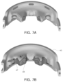
- FIGS. 7 A and 7 B are views illustrating improvement of contact pressure of a stopper in a hydro bushing according to an exemplary embodiment in the present disclosure.
- first,” “second,” and “third” may be used herein to describe various members, components, regions, layers, or sections, these members, components, regions, layers, or sections are not to be limited by these terms. Rather, these terms are only used to distinguish one member, component, region, layer, or section from another member, component, region, layer, or section.
- a first member, component, region, layer, or section referred to in examples described herein may, in one example, also be referred to as a second member, component, region, layer, or section without departing from the teachings of the examples.
- FIG. 1 is a perspective view illustrating a hydro bushing according to an exemplary embodiment
- FIG. 2 is an exploded perspective view of FIG. 1 .
- the hydro bushing may include an outer pipe 10 , an inner pipe 20 , an elastic body 30 , and a nozzle 40 .
- the outer pipe 10 may be a substantially tubular member and may have a hollow portion therein.
- the nozzle 40 , the elastic body 30 , and the inner pipe 20 may be inserted from an internal surface of the outer pipe 10 to be disposed and coupled.
- the outer pipe 10 may be formed of a rigid material, such as a metal or reinforced plastic, to protect components inserted thereinto and to be prevented from being deformed or damaged.
- the outer pipe 10 may be press-fitted and coupled to one end of a lower arm constituting a suspension when, for example, the hydro bushing of the present disclosure is applied to the suspension to absorb shocks, vibrations, and the like, generated by a wheel or an engine of the vehicle.
- a coupling method are limited to the above-described example.
- the inner pipe 20 may be a substantially tubular member, and may have a hollow portion therein.
- the elastic body 30 may be fitted and coupled to an external surface of the inner pipe over at least a portion of an entire length of the inner pipe.
- the inner pipe and the elastic body may be bonded to each other by an adhesive or integrally molded by insert injection.
- the inner pipe 20 coupled to the elastic body 30 may be disposed to be spaced apart from the outer pipe within the outer pipe 10 and to penetrate through the outer pipe 10 .
- the inner pipe may be held within the outer pipe by, for example, an elastic body press-fitted into the outer pipe 10 .
- the inner pipe 20 may be formed of a rigid material such as a metal or reinforced plastic to prevent deformation or damage thereof.
- the inner pipe 20 may be coupled to a frame of a vehicle body using a mounting bolt penetrating through the hollow portion of the inner pipe 20 when, for example, a hydro bushing of the present disclosure is applied to a suspension to absorb shocks, vibrations, and the like, generated by a wheel or an engine of a vehicle, to connect a lower arm constituting the suspension to the vehicle body.
- a hydro bushing of the present disclosure is applied to a suspension to absorb shocks, vibrations, and the like, generated by a wheel or an engine of a vehicle, to connect a lower arm constituting the suspension to the vehicle body.
- such an application object and such a connection portion are not limited to the above-described example.
- the inner pipe 20 may further include a pair of protrusions 21 formed to outwardly protrude from the external surface in a radial direction.
- the pair of protrusions may be formed to extend over the entire length of the inner pipe 20 , but exemplary embodiments are not limited thereto.
- the pair of protrusions 21 may be formed to extend according to a length of an elastic body fitted into the inner pipe 20 to extend in a length direction of the inner pipe 20 (a vertical direction in the drawings).
- the inner pipe 20 may be provided with the protrusion 21 , protruding toward the outer pipe 10 , to increase bondability between the inner pipe 20 and the elastic body 30 .
- the inner pipe 20 may more firmly support the elastic body, and a decrease in rigidity of the elastic body 30 caused by compression of the elastic body 30 may be prevented.
- the elastic body 30 may be provided between the outer pipe 10 and the inner pipe 20 .
- the elastic body 30 may be fitted into the inner pipe 20 to be bonded to the inner pipe 20 by an adhesive or insert injection, and may be press-fitted into the outer pipe 10 .
- the elastic body 30 may be disposed between the inner pipe 20 and the nozzle 40 .
- the elastic body 30 may absorb shocks and vibrations transmitted from an external entity through the inner pipe 20 .
- the elastic body 30 may be formed of, for example, an elastic material such as a rubber or a synthetic resin.
- the elastic body 30 may include a liquid chamber portion 31 supporting displacement of the inner pipe 20 to more effectively absorb shocks and vibrations transmitted to the inner pipe 20 and to be stably bonded to the inner pipe 20 , and a bonding portion 32 bonded to an external surface of the inner pipe 20 by an adhesive or insert injection.
- the liquid chamber portion 31 may be formed to be inwardly concave from the external surface of the elastic body 30 in a radial direction.
- the bonding portion 32 may be formed as an inner circumferential surface of a hole penetrating through the elastic body 30 in the vertical direction, and may be formed to extend by a length, slightly less than an entire length of the inner pipe 20 .
- the elastic body 30 may include a space portion 33 formed therein to prevent the liquid chamber portion 31 from being damaged by excessive displacement of the inner pipe 20 and to absorb the displacement.
- the elastic body 30 may include a support portion 34 extending outwardly from the bonding portion 32 in a radial direction and relatively protruding further than the liquid chamber portion 31 to be in contact with the nozzle 40 to secure damping force.
- the nozzle 40 may be disposed between the outer pipe and the elastic body 30 , and may include a pair of nozzle members 41 and 42 formed to be symmetrical to each other. Since the pair of nozzle members 41 and 42 are coupled to the elastic body 30 to surround the elastic body 30 , an assembling property of the nozzle 40 and the elastic body 30 may be improved.
- the nozzle 40 for example, the pair of nozzle members 41 and 42 may be formed of a moldable material such as plastic.
- a material of the pair of nozzles 41 and 42 may be engineering plastic or reinforced plastics having characteristics such as moldability, shock resistance, wear-resistance, heat resistance, and the like, but is not necessarily limited thereto.
- the pair of nozzle members 41 and 42 may be disposed such that opposite side end portions thereof in a circumferential direction are adjacent to each other or in contact with each other within the outer pipe 10 , and may be disposed to surround the elastic body 30 , for example, the liquid chamber portion 31 of the elastic body 30 at an approximately intermediate height of the outer pipe 10 . Accordingly, the nozzle 40 may be disposed between the outer pipe 10 and the inner pipe 20 , for example, between the outer pipe 10 and the elastic body 30 .
- opposite end portions of one nozzle member 41 and the other nozzle member 42 may face each other to form a nozzle 40 having a substantially tubular shape.
- the pair of nozzle members 41 and 42 may be formed to have a substantially semicircular cross-section.
- the one nozzle member 41 and the other nozzle member 42 may seal spaces between the nozzle members 41 and 42 and the liquid chamber portion 31 of the elastic body 30 , respectively, to prevent a fluid from leaking between each of the nozzle members 41 and 42 and the liquid chamber portion 31 of the elastic body.
- a space between each of the nozzle members 41 and 42 and the liquid chamber portion 31 of the elastic body 30 will be referred to as a hydraulic chamber 43 .
- external surfaces of the one nozzle member 41 and the other nozzle member 42 may be in close contact with the internal surface of the outer pipe 10 .
- At least one flow path portion 45 may be formed on the external surface of each of the nozzle members 41 and 42 in the circumferential direction.
- a through-hole 46 communicating with the hydraulic chamber 43 , may be formed in an end portion of the flow path portion.
- the fluid present in the hydraulic chamber 43 between the nozzle members 41 and 42 and the elastic body 30 may flow along the flow path portion 45 as an elastic body is deformed and a volume of a hydraulic chamber is changed by transmitted shocks and vibrations.
- a frequency of a predetermined frequency band may be controlled and tuned by the hydraulic chamber and the flow path portion.
- a plurality of flow path portions 45 may be formed in each of the nozzle members 41 and 42 , and one of the flow path portions of one nozzle member and one of the flow path portions of the other nozzle member may be connected to each other during assembling of the nozzle 40 to form a substantially spiral flow path portion.
- the nozzle 40 for example, the pair of nozzle members 41 and 42 may include at least one stopper 47 formed by a portion of an internal surface of the nozzle protruding inwardly in a radial direction.
- examples in which a plurality of stoppers are formed on each nozzle member may be provided.
- the stopper 47 of the one nozzle member 41 may be formed and disposed in a position symmetrical to the stopper 47 of the other nozzle member 42 in a radial direction with respect to the center of the inner pipe 20 .
- the number and position of the stoppers 47 may appropriately vary depending on a design need.
- a thickness of the stopper (a length in the vertical direction in the drawings) and a distance between the stopper 47 and the inner pipe 20 may be changed to satisfy conditions required during a design.
- the stopper 47 may be disposed inside the hydraulic chamber 43 to be spaced apart from the liquid chamber 31 of the elastic body 30 , and may support displacement of the inner pipe 20 caused by the external shocks and vibrations.
- the stopper 47 may be inserted into the liquid chamber portion of the elastic body 30 between the elastic body 30 and the outer pipe 10 to pressurize the liquid chamber portion 31 in a radial direction of the elastic body 30 such that excessive displacement of the inner pipe 20 is prevented and the inner pipe 31 is supported via the liquid chamber portion 31 to smoothly absorb shocks and vibrations.
- the stopper 47 may support the inner pipe 20 together with the liquid chamber portion 31 of the elastic body 30 .
- the stopper 47 may be inserted into the liquid chamber portion 31 to apply a reaction force caused by displacement of the inner pipe 20 to the inner pipe 20 through the liquid chamber portion 31 , thereby supporting the displacement of the inner pipe 20 and preventing excessive displacement of the inner pipe 20 .
- the support portion 34 of the elastic body 30 may be brought into contact with the internal surface of the nozzle 40 to support the nozzle 40 , and the liquid chamber portion 31 of the elastic body 30 may be brought into contact with a contact end 48 of the stopper 47 to support the nozzle 40 , so that shock-absorbing force against shocks or damping force against vibrations of the elastic body 30 may be secured.
- the inner pipe 20 coupled to the elastic body 30 and receiving external shocks and vibrations may be supported by the nozzle 40 and the stopper 47 through the elastic body 30 , and the shocks, vibrations and the displacement of the inner pipe 20 may be absorbed by the elastic body 30 .
- the hydro bushing may include an intermediate pipe 50 embedded in the elastic body 30 .
- the intermediate pipe 50 may have openings 51 respectively formed on opposite sides thereof to correspond to the hydraulic chamber 43 .
- the openings 51 on the opposite sides of the intermediate pipe 50 may allow the inside and the outside of the intermediate pipe to communicate with each other.
- ring-shaped portions 52 formed in a circumferential direction of the intermediate pipe may be disposed on opposite ends of the intermediate pipe 50 in a vertical direction, respectively.
- the intermediate pipe 50 may be formed of a moldable material such as plastic. However, exemplary embodiments are not limited thereto, and the intermediate pipe 50 may be formed of, for example, a metal.
- the intermediate pipe 50 may be molded to be integrated with the elastic body 30 by insert injection. In this case, the intermediate pipe 50 and the elastic body 30 may be prevented from being separated from each other.
- the shocks and vibrations transmitted from the outside to the elastic body 30 may be dispersed by the intermediate pipe 50 , so that the hydro bushing of the present disclosure may have rigidity and durability enough to withstand greater shocks and vibrations.
- a conical movement may occur due to bumping or rebounding of a wheel.
- conical movement means that, for example, when a hydro bushing is applied to a suspension of a vehicle, a lower arm constituting the suspension moves on a conical trajectory around the hydro bushing.
- the elastic body 30 may be brought into contact with the nozzle 40 while being deformed, and the elastic body 30 brought into contact with the nozzle 40 may be excessively worn. In a worse case, the elastic body 30 or the nozzle 40 may be damaged.
- FIG. 3 is a transverse cross-sectional view of FIG. 1
- FIG. 4 is a longitudinal cross-sectional view of FIG. 1
- FIG. 5 is an enlarged cross-sectional view of portion “A” of FIG. 4 , illustrating an action of a hydro bushing according to an exemplary embodiment
- FIG. 6 is a cross-sectional view illustrating a conical movement state of a hydro bushing according to an exemplary embodiment.
- the hydro bushing according to an exemplary embodiment allows the contact end 48 of the stopper 47 to be in contact with the liquid chamber portion 31 with a maximum area depending on the deformation of the elastic body 30 .
- the hydro bushing according to an exemplary embodiment may reduce contact pressure applied to the stopper 47 to delay wear of the elastic body 30 , resulting in improved durability of an entire bush.
- a main load direction may approximately correspond to a front-rear direction of the vehicle.
- a gap N in the load direction may be present between the nozzle 40 and the elastic body 30 .
- the gap N in the load direction may be calculated by reflecting a shape of the elastic body 30 of the hydro bushing and an input load. In particular, it is important to manage a maximum value of a primary characteristic section and a start value of a secondary characteristic section required for ride quality and handling performance of the vehicle.
- the primary characteristic section is a section, in which a load is gradually increased or decreased depending on displacement, in a characteristic line diagram of the displacement for the load of the bushing, and the secondary characteristic section refers to a section, in which the load is rapidly increased or decreased, compared with the previous displacement, in the characteristic line diagram.
- the gap N may be determined to be 1.5 to 3 mm.
- the ride quality may be deteriorated.
- the gap N is greater than 3 mm, the handling performance may be adversely affected.
- an imaginary circle (a virtual circle) (X of FIG. 3 ) maintaining an outer diameter of the inner pipe 20 may be moved by the gap with respect to a center point of the inner pipe 20 , and a radius of the imaginary circle X, equal to an outer radius of the inner pipe 20 , may be determined as a circumferential curvature of a surface of the contact end 48 of the stopper 47 , as illustrated in FIG. 3 .
- the surface of the contact end 48 of the stopper 47 may have a circumferential shape curved by a circumferential curvature, equal to the outer radius of the inner pipe 20 .
- a distance obtained by summing an outer radius of an inner pipe and a gap was determined as a circumferential curvature (a dashed line Y of FIG. 3 ) of a surface of the contact end of the stopper 47 , based on a center point of the inner pipe 20 .
- the surface of the contact end 48 of the stopper 47 may have a shape corresponding to an elastic body contacting while being deformed in advance depending on conical movement.
- an angle of a corner portion, disposed to be adjacent to the support portion 34 of the elastic body 30 , in the contact end 48 of the stopper 47 may be greater than an angle of a corresponding corner portion present in a stopper according to the related art which has a circumferential curvature that is a distance obtained by summing the outer radius of the inner pipe 20 and the gap.
- an angle of a corner portion, relatively distant from the support portion 34 of the elastic body 30 , in the contact ends 48 of the stopper 47 may be smaller than an angle of a corresponding corner portion present in a stopper according to the related art which has a circumferential curvature that is a distance obtained by summing the outer radius of the inner pipe 20 and the gap.
- a contact area between the surface of the contact end 48 of the stopper 47 and the elastic body 30 , for example, an internal surface of the liquid chamber portion 31 deformed during the conical movement may be secured to be maximum.
- the surface of the contact end 48 of the stopper 47 may have a shape in a thickness direction, including a linear section L extending in the thickness direction and a curved section C continuous with the linear section L and brought into contact with the elastic body 30 during conical movement.
- the inner pipe 20 may be relatively inclined by a predetermined angle with respect to the outer pipe 10 .
- the predetermined angle will be referred to as a conical angle ⁇ .
- the conical angle ⁇ may be determined to range from ⁇ 9 degrees to +9 degrees.
- a length of the linear section L corresponding to 10 to 30% of an entire stopper thickness while including a center of a thickness T of the stopper may be set on the surface of the contact end 48 of the stopper 47 , as illustrated in FIGS. 4 and 5 .
- a virtual line inclined by the conical angle ⁇ with respect to a reference line O, extending in parallel to an axial line of the outer pipe 10 or the inner pipe 20 may extend from one start point S of the linear section L.
- the stopper may not sufficiently support a load transmitted through the inner pipe 20 and the elastic body 30 in a state in which there is no conical movement. Thus, wear of the elastic body 30 may be accelerated.
- the linear section L of the stopper may interfere with the elastic body 30 during the conical movement, to cause wear of the elastic body 10 or damage to the nozzle 40 .
- a shape of the curved section C may be determined along a curve having a predetermined curvature and connecting one start point S of the linear section L and the end point P on the one side surface to each other.
- the shape of the surface of the contact end 48 of the stopper 47 in the thickness direction may include a linear section L contacting the elastic body 30 in the load direction in a state in which there is no conical movement, and a pair of curved sections C contacting the elastic body 30 due to the inner pipe 20 relatively inclined with respect to the outer pipe 10 during the conical movement.
- the surface of the contact end 48 of the stopper 47 in the thickness direction is determined by reflecting the conical angle ⁇ of the inner pipe 20 relatively inclined with respect to the axis of the outer pipe 10 during the conical movement, the surface of the contact end 48 of the stopper 47 has a shape corresponding to the elastic body that is in contact while being deformed depending on the conical movement in advance.
- a length of the linear section L on the contact end 48 of the stopper 47 may be smaller than a length of a linear section in a stopper according to the related art.
- a length of the curved section C on the contact end 48 of the stopper 47 may be greater than a length of a curved section on a simply chamfering level in the stopper according to the related art.
- a contact area between the surface of the contact end 48 of the stopper 47 and the elastic body 30 , for example, an internal surface of the liquid chamber portion 31 deformed during the conical movement may be secured to be maximum, as illustrated in FIG. 6 .
- FIGS. 7 A and 7 B are views illustrating improvement of contact pressure of a stopper in a hydro bushing according to an exemplary embodiment.
- the applicant of the present disclosure analyzed a contact pressure acting on a stopper 47 through simulation for a hydro bushing of the present disclosure.
- a circumferential shape of the surface of the contact end 48 of the stopper 47 was determined by an outer radius of an inner pipe disposed by moving a center point of the inner pipe 20 by a gap N, and a shape of the contact end 48 of the stopper 47 in a thickness direction was determined by reflecting a conical angle ⁇ of the inner pipe 20 relatively inclined with respect to an axial line of the outer pipe 10 during the conical movement and a decreased length of a linear section L. Accordingly, the surface of the contact end 48 on the stopper of the nozzle 40 may be brought into contact with the elastic body 30 with a maximum area, so that contact pressure may be distributed.
- the contact pressure received by the contact end 48 of the stopper 47 may be reduced by about 30% in the hydro bushing of the present disclosure, as compared with the hydro bushing according to the related art.
- the elastic body 30 in contact with the nozzle 40 may prevented from being excessively worn or damage to the elastic body 30 or the nozzle may be prevented in spite of greater conical movement and load caused by bumping or rebounding of a wheel.
- durability of the entire bushing may be improved.
- the durability of the entire bushing may be improved while maintaining noise, vibrations, and harshness (NVH) reduction performance.
- NSH harshness
Landscapes
- Engineering & Computer Science (AREA)
- General Engineering & Computer Science (AREA)
- Mechanical Engineering (AREA)
- Physics & Mathematics (AREA)
- Acoustics & Sound (AREA)
- Aviation & Aerospace Engineering (AREA)
- Springs (AREA)
- Combined Devices Of Dampers And Springs (AREA)
Abstract
Description
Claims (6)
Applications Claiming Priority (2)
| Application Number | Priority Date | Filing Date | Title |
|---|---|---|---|
| KR10-2022-0047991 | 2022-04-19 | ||
| KR1020220047991A KR20230149367A (en) | 2022-04-19 | 2022-04-19 | Hydro bush |
Publications (2)
| Publication Number | Publication Date |
|---|---|
| US20230332667A1 US20230332667A1 (en) | 2023-10-19 |
| US12222015B2 true US12222015B2 (en) | 2025-02-11 |
Family
ID=88308551
Family Applications (1)
| Application Number | Title | Priority Date | Filing Date |
|---|---|---|---|
| US17/973,053 Active 2043-03-02 US12222015B2 (en) | 2022-04-19 | 2022-10-25 | Hydro bushing |
Country Status (3)
| Country | Link |
|---|---|
| US (1) | US12222015B2 (en) |
| KR (1) | KR20230149367A (en) |
| CN (1) | CN116906494A (en) |
Families Citing this family (3)
| Publication number | Priority date | Publication date | Assignee | Title |
|---|---|---|---|---|
| KR20230149367A (en) * | 2022-04-19 | 2023-10-27 | 현대자동차주식회사 | Hydro bush |
| KR20250033536A (en) * | 2023-08-31 | 2025-03-10 | 현대모비스 주식회사 | Insulator for suspension apparatus |
| KR102683451B1 (en) | 2024-03-20 | 2024-07-10 | 평화산업주식회사 | Exhaust structure of mold using 3d printing |
Citations (13)
| Publication number | Priority date | Publication date | Assignee | Title |
|---|---|---|---|---|
| US5022673A (en) | 1989-02-03 | 1991-06-11 | Honda Giken Kogyo Kabushiki Kaisha | Wheel suspension system for automobiles |
| US20030178754A1 (en) * | 2002-03-25 | 2003-09-25 | Franck Larmande | Hydraulic anti-vibration sleeve |
| JP2006144837A (en) | 2004-11-16 | 2006-06-08 | Toyota Motor Corp | Stabilizer bush |
| US7252298B2 (en) | 2000-09-05 | 2007-08-07 | Meritor Heavy Vehicle Systems Limited | Pivot bearing |
| US20070273076A1 (en) * | 2006-03-30 | 2007-11-29 | Tokai Rubber Industries, Ltd. | Cylindrical fluid-filled elastic mount |
| US7306209B2 (en) | 2003-04-04 | 2007-12-11 | ZF Lemförder Metallwaren AG | Hydraulically damping rubber bush bearing for vertical mounting |
| US20090189323A1 (en) * | 2008-01-29 | 2009-07-30 | Tokai Rubber Industries, Ltd. | Fluid filled type cylindrical vibration damping device |
| KR101122974B1 (en) | 2009-11-11 | 2012-03-16 | (주) 디에이치홀딩스 | Lower arm for vehicle |
| US20160084340A1 (en) * | 2014-09-19 | 2016-03-24 | Yamashita Rubber Kabushiki Kaisha | Vibration isolating bushing |
| JP6148897B2 (en) | 2013-04-26 | 2017-06-14 | 住友理工株式会社 | Stabilizer bush |
| US20170299008A1 (en) * | 2014-10-03 | 2017-10-19 | Bridgestone Corporation | Vibration damping device |
| US20180216666A1 (en) | 2017-02-02 | 2018-08-02 | Ford Global Technologies, Llc | Bearing arrangement |
| US20230332667A1 (en) * | 2022-04-19 | 2023-10-19 | Hyundai Motor Company | Hydro bushing |
-
2022
- 2022-04-19 KR KR1020220047991A patent/KR20230149367A/en active Pending
- 2022-10-25 US US17/973,053 patent/US12222015B2/en active Active
- 2022-11-17 CN CN202211460548.5A patent/CN116906494A/en active Pending
Patent Citations (13)
| Publication number | Priority date | Publication date | Assignee | Title |
|---|---|---|---|---|
| US5022673A (en) | 1989-02-03 | 1991-06-11 | Honda Giken Kogyo Kabushiki Kaisha | Wheel suspension system for automobiles |
| US7252298B2 (en) | 2000-09-05 | 2007-08-07 | Meritor Heavy Vehicle Systems Limited | Pivot bearing |
| US20030178754A1 (en) * | 2002-03-25 | 2003-09-25 | Franck Larmande | Hydraulic anti-vibration sleeve |
| US7306209B2 (en) | 2003-04-04 | 2007-12-11 | ZF Lemförder Metallwaren AG | Hydraulically damping rubber bush bearing for vertical mounting |
| JP2006144837A (en) | 2004-11-16 | 2006-06-08 | Toyota Motor Corp | Stabilizer bush |
| US20070273076A1 (en) * | 2006-03-30 | 2007-11-29 | Tokai Rubber Industries, Ltd. | Cylindrical fluid-filled elastic mount |
| US20090189323A1 (en) * | 2008-01-29 | 2009-07-30 | Tokai Rubber Industries, Ltd. | Fluid filled type cylindrical vibration damping device |
| KR101122974B1 (en) | 2009-11-11 | 2012-03-16 | (주) 디에이치홀딩스 | Lower arm for vehicle |
| JP6148897B2 (en) | 2013-04-26 | 2017-06-14 | 住友理工株式会社 | Stabilizer bush |
| US20160084340A1 (en) * | 2014-09-19 | 2016-03-24 | Yamashita Rubber Kabushiki Kaisha | Vibration isolating bushing |
| US20170299008A1 (en) * | 2014-10-03 | 2017-10-19 | Bridgestone Corporation | Vibration damping device |
| US20180216666A1 (en) | 2017-02-02 | 2018-08-02 | Ford Global Technologies, Llc | Bearing arrangement |
| US20230332667A1 (en) * | 2022-04-19 | 2023-10-19 | Hyundai Motor Company | Hydro bushing |
Also Published As
| Publication number | Publication date |
|---|---|
| US20230332667A1 (en) | 2023-10-19 |
| KR20230149367A (en) | 2023-10-27 |
| CN116906494A (en) | 2023-10-20 |
Similar Documents
| Publication | Publication Date | Title |
|---|---|---|
| US12222015B2 (en) | Hydro bushing | |
| EP0723091B1 (en) | Fluid-filled elastic bushing having displacement restrictor with elastic buffer and stiff abutting part | |
| US11073191B2 (en) | Fluid-filled tubular vibration-damping device | |
| US7845624B2 (en) | Cylindrical fluid-filled elastic mount | |
| US20190186586A1 (en) | Bushing | |
| US8231115B2 (en) | Very high damping body mount, subframe mount or engine mount with bolt-through construction | |
| US20040239020A1 (en) | Fluid filled cylindrical vibration damping device | |
| JP6251729B2 (en) | Liquid seal type vibration isolator | |
| JP4011877B2 (en) | Arm link structure | |
| KR20120033836A (en) | Hydraulic bush | |
| JP6898273B2 (en) | Liquid-filled anti-vibration device | |
| US20240198749A1 (en) | Hydro bushing | |
| US11668364B2 (en) | Gas cup for a damper assembly and a damper assembly | |
| KR20220017235A (en) | Mounting bush for vehicle | |
| CN121429755A (en) | Hydraulic bushings and vehicles | |
| KR102878778B1 (en) | Mounts with Linear and Non-Linear Stiffness | |
| KR102604385B1 (en) | Caulking type sliding bush | |
| KR200287282Y1 (en) | Piston Ring Coupling Structure of Shock Absorber_ | |
| JP7424954B2 (en) | Vibration isolator | |
| JP2008249079A (en) | Fluid filled toe collect bush | |
| JP7034424B2 (en) | Liquid-filled anti-vibration device and vehicle anti-vibration structure | |
| CN114857205B (en) | Control arm hydraulic bushing and vehicle | |
| WO2020129367A1 (en) | Liquid seal bushing | |
| JP6147102B2 (en) | Liquid-filled vibration isolator | |
| KR20240113181A (en) | Bushing for vehicle with coupling structure for different materials |
Legal Events
| Date | Code | Title | Description |
|---|---|---|---|
| FEPP | Fee payment procedure |
Free format text: ENTITY STATUS SET TO UNDISCOUNTED (ORIGINAL EVENT CODE: BIG.); ENTITY STATUS OF PATENT OWNER: LARGE ENTITY |
|
| AS | Assignment |
Owner name: PYUNG HWA INDUSTRIAL CO., LTD., KOREA, REPUBLIC OF Free format text: ASSIGNMENT OF ASSIGNORS INTEREST;ASSIGNORS:RYU, YONG HYUN;PARK, CHAN HEE;KIM, YOUNG HO;AND OTHERS;REEL/FRAME:061535/0640 Effective date: 20221013 Owner name: KIA CORPORATION, KOREA, REPUBLIC OF Free format text: ASSIGNMENT OF ASSIGNORS INTEREST;ASSIGNORS:RYU, YONG HYUN;PARK, CHAN HEE;KIM, YOUNG HO;AND OTHERS;REEL/FRAME:061535/0640 Effective date: 20221013 Owner name: HYUNDAI MOTOR COMPANY, KOREA, REPUBLIC OF Free format text: ASSIGNMENT OF ASSIGNORS INTEREST;ASSIGNORS:RYU, YONG HYUN;PARK, CHAN HEE;KIM, YOUNG HO;AND OTHERS;REEL/FRAME:061535/0640 Effective date: 20221013 |
|
| STPP | Information on status: patent application and granting procedure in general |
Free format text: DOCKETED NEW CASE - READY FOR EXAMINATION |
|
| STPP | Information on status: patent application and granting procedure in general |
Free format text: NON FINAL ACTION MAILED |
|
| STPP | Information on status: patent application and granting procedure in general |
Free format text: RESPONSE TO NON-FINAL OFFICE ACTION ENTERED AND FORWARDED TO EXAMINER |
|
| STPP | Information on status: patent application and granting procedure in general |
Free format text: FINAL REJECTION MAILED |
|
| STPP | Information on status: patent application and granting procedure in general |
Free format text: RESPONSE AFTER FINAL ACTION FORWARDED TO EXAMINER |
|
| STPP | Information on status: patent application and granting procedure in general |
Free format text: NOTICE OF ALLOWANCE MAILED -- APPLICATION RECEIVED IN OFFICE OF PUBLICATIONS |
|
| ZAAB | Notice of allowance mailed |
Free format text: ORIGINAL CODE: MN/=. |
|
| STPP | Information on status: patent application and granting procedure in general |
Free format text: PUBLICATIONS -- ISSUE FEE PAYMENT VERIFIED |
|
| STCF | Information on status: patent grant |
Free format text: PATENTED CASE |