US12221822B2 - Door operation management system - Google Patents
Door operation management system Download PDFInfo
- Publication number
- US12221822B2 US12221822B2 US17/616,835 US202017616835A US12221822B2 US 12221822 B2 US12221822 B2 US 12221822B2 US 202017616835 A US202017616835 A US 202017616835A US 12221822 B2 US12221822 B2 US 12221822B2
- Authority
- US
- United States
- Prior art keywords
- door
- management system
- operation management
- state
- remote
- Prior art date
- Legal status (The legal status is an assumption and is not a legal conclusion. Google has not performed a legal analysis and makes no representation as to the accuracy of the status listed.)
- Active, expires
Links
- 238000012545 processing Methods 0.000 claims abstract description 33
- 238000000034 method Methods 0.000 claims abstract description 26
- 238000004590 computer program Methods 0.000 claims abstract description 20
- 238000004891 communication Methods 0.000 claims description 46
- 230000001133 acceleration Effects 0.000 claims description 15
- 238000007726 management method Methods 0.000 description 59
- 230000008901 benefit Effects 0.000 description 9
- 238000012423 maintenance Methods 0.000 description 4
- 238000009434 installation Methods 0.000 description 3
- 230000000903 blocking effect Effects 0.000 description 2
- 230000003247 decreasing effect Effects 0.000 description 2
- 230000007812 deficiency Effects 0.000 description 2
- 238000012986 modification Methods 0.000 description 2
- 230000004048 modification Effects 0.000 description 2
- 230000006870 function Effects 0.000 description 1
- 230000007774 longterm Effects 0.000 description 1
- 238000010295 mobile communication Methods 0.000 description 1
Images


Classifications
-
- E—FIXED CONSTRUCTIONS
- E05—LOCKS; KEYS; WINDOW OR DOOR FITTINGS; SAFES
- E05F—DEVICES FOR MOVING WINGS INTO OPEN OR CLOSED POSITION; CHECKS FOR WINGS; WING FITTINGS NOT OTHERWISE PROVIDED FOR, CONCERNED WITH THE FUNCTIONING OF THE WING
- E05F15/00—Power-operated mechanisms for wings
- E05F15/70—Power-operated mechanisms for wings with automatic actuation
- E05F15/77—Power-operated mechanisms for wings with automatic actuation using wireless control
-
- G—PHYSICS
- G05—CONTROLLING; REGULATING
- G05B—CONTROL OR REGULATING SYSTEMS IN GENERAL; FUNCTIONAL ELEMENTS OF SUCH SYSTEMS; MONITORING OR TESTING ARRANGEMENTS FOR SUCH SYSTEMS OR ELEMENTS
- G05B15/00—Systems controlled by a computer
- G05B15/02—Systems controlled by a computer electric
-
- G—PHYSICS
- G08—SIGNALLING
- G08B—SIGNALLING OR CALLING SYSTEMS; ORDER TELEGRAPHS; ALARM SYSTEMS
- G08B13/00—Burglar, theft or intruder alarms
- G08B13/02—Mechanical actuation
- G08B13/08—Mechanical actuation by opening, e.g. of door, of window, of drawer, of shutter, of curtain, of blind
-
- E—FIXED CONSTRUCTIONS
- E05—LOCKS; KEYS; WINDOW OR DOOR FITTINGS; SAFES
- E05B—LOCKS; ACCESSORIES THEREFOR; HANDCUFFS
- E05B45/00—Alarm locks
- E05B45/06—Electric alarm locks
- E05B2045/063—Electric alarm locks by movement of the wing
-
- E—FIXED CONSTRUCTIONS
- E05—LOCKS; KEYS; WINDOW OR DOOR FITTINGS; SAFES
- E05B—LOCKS; ACCESSORIES THEREFOR; HANDCUFFS
- E05B45/00—Alarm locks
- E05B45/06—Electric alarm locks
- E05B2045/065—Switch or sensor type used in alarm locks
- E05B2045/067—Switches triggered by inertia
-
- E—FIXED CONSTRUCTIONS
- E05—LOCKS; KEYS; WINDOW OR DOOR FITTINGS; SAFES
- E05B—LOCKS; ACCESSORIES THEREFOR; HANDCUFFS
- E05B47/00—Operating or controlling locks or other fastening devices by electric or magnetic means
- E05B2047/0048—Circuits, feeding, monitoring
- E05B2047/0067—Monitoring
- E05B2047/0068—Door closed
-
- E—FIXED CONSTRUCTIONS
- E05—LOCKS; KEYS; WINDOW OR DOOR FITTINGS; SAFES
- E05Y—INDEXING SCHEME ASSOCIATED WITH SUBCLASSES E05D AND E05F, RELATING TO CONSTRUCTION ELEMENTS, ELECTRIC CONTROL, POWER SUPPLY, POWER SIGNAL OR TRANSMISSION, USER INTERFACES, MOUNTING OR COUPLING, DETAILS, ACCESSORIES, AUXILIARY OPERATIONS NOT OTHERWISE PROVIDED FOR, APPLICATION THEREOF
- E05Y2400/00—Electronic control; Electrical power; Power supply; Power or signal transmission; User interfaces
- E05Y2400/10—Electronic control
- E05Y2400/32—Position control, detection or monitoring
- E05Y2400/35—Position control, detection or monitoring related to specific positions
- E05Y2400/354—End positions
-
- E—FIXED CONSTRUCTIONS
- E05—LOCKS; KEYS; WINDOW OR DOOR FITTINGS; SAFES
- E05Y—INDEXING SCHEME ASSOCIATED WITH SUBCLASSES E05D AND E05F, RELATING TO CONSTRUCTION ELEMENTS, ELECTRIC CONTROL, POWER SUPPLY, POWER SIGNAL OR TRANSMISSION, USER INTERFACES, MOUNTING OR COUPLING, DETAILS, ACCESSORIES, AUXILIARY OPERATIONS NOT OTHERWISE PROVIDED FOR, APPLICATION THEREOF
- E05Y2400/00—Electronic control; Electrical power; Power supply; Power or signal transmission; User interfaces
- E05Y2400/10—Electronic control
- E05Y2400/36—Speed control, detection or monitoring
- E05Y2400/37—Speed control, detection or monitoring by using acceleration sensors
-
- E—FIXED CONSTRUCTIONS
- E05—LOCKS; KEYS; WINDOW OR DOOR FITTINGS; SAFES
- E05Y—INDEXING SCHEME ASSOCIATED WITH SUBCLASSES E05D AND E05F, RELATING TO CONSTRUCTION ELEMENTS, ELECTRIC CONTROL, POWER SUPPLY, POWER SIGNAL OR TRANSMISSION, USER INTERFACES, MOUNTING OR COUPLING, DETAILS, ACCESSORIES, AUXILIARY OPERATIONS NOT OTHERWISE PROVIDED FOR, APPLICATION THEREOF
- E05Y2400/00—Electronic control; Electrical power; Power supply; Power or signal transmission; User interfaces
- E05Y2400/10—Electronic control
- E05Y2400/44—Sensors not directly associated with the wing movement
-
- E—FIXED CONSTRUCTIONS
- E05—LOCKS; KEYS; WINDOW OR DOOR FITTINGS; SAFES
- E05Y—INDEXING SCHEME ASSOCIATED WITH SUBCLASSES E05D AND E05F, RELATING TO CONSTRUCTION ELEMENTS, ELECTRIC CONTROL, POWER SUPPLY, POWER SIGNAL OR TRANSMISSION, USER INTERFACES, MOUNTING OR COUPLING, DETAILS, ACCESSORIES, AUXILIARY OPERATIONS NOT OTHERWISE PROVIDED FOR, APPLICATION THEREOF
- E05Y2400/00—Electronic control; Electrical power; Power supply; Power or signal transmission; User interfaces
- E05Y2400/65—Power or signal transmission
- E05Y2400/66—Wireless transmission
-
- E—FIXED CONSTRUCTIONS
- E05—LOCKS; KEYS; WINDOW OR DOOR FITTINGS; SAFES
- E05Y—INDEXING SCHEME ASSOCIATED WITH SUBCLASSES E05D AND E05F, RELATING TO CONSTRUCTION ELEMENTS, ELECTRIC CONTROL, POWER SUPPLY, POWER SIGNAL OR TRANSMISSION, USER INTERFACES, MOUNTING OR COUPLING, DETAILS, ACCESSORIES, AUXILIARY OPERATIONS NOT OTHERWISE PROVIDED FOR, APPLICATION THEREOF
- E05Y2800/00—Details, accessories and auxiliary operations not otherwise provided for
- E05Y2800/26—Form or shape
- E05Y2800/30—Form or shape inclined, angled
-
- E—FIXED CONSTRUCTIONS
- E05—LOCKS; KEYS; WINDOW OR DOOR FITTINGS; SAFES
- E05Y—INDEXING SCHEME ASSOCIATED WITH SUBCLASSES E05D AND E05F, RELATING TO CONSTRUCTION ELEMENTS, ELECTRIC CONTROL, POWER SUPPLY, POWER SIGNAL OR TRANSMISSION, USER INTERFACES, MOUNTING OR COUPLING, DETAILS, ACCESSORIES, AUXILIARY OPERATIONS NOT OTHERWISE PROVIDED FOR, APPLICATION THEREOF
- E05Y2900/00—Application of doors, windows, wings or fittings thereof
- E05Y2900/10—Application of doors, windows, wings or fittings thereof for buildings or parts thereof
- E05Y2900/13—Type of wing
- E05Y2900/132—Doors
Definitions
- the disclosure pertains to the field of controlling a status of a door.
- a door can be either in an open state or in a closed state.
- a switch that is e.g. mounted on a doorframe, which is actuated by the door itself and serves as a gauge for determining if the door is closed. Implicitly if the switch is not actuated one conclusion is that the door is open.
- a door closing device or a door opening device is used together with e.g. a swing door
- mechanical gauges can be used to determine a movement of the door and thereby determine if a door is an open state or a closed state.
- An object of the present disclosure is to provide system, method and computer program product for controlling the operation of a door which seek to mitigate, alleviate, or eliminate one or more of the above-identified deficiencies in the art and disadvantages singly or in any combination.
- the disclosure proposes a door operation management system for controlling operation of a door.
- the door operation management system comprises at least a first movement sensor device arranged at the door, for determining a movement of the door and a processing circuitry operatively connected to the at least first movement sensor device.
- the processing circuitry is configured to cause the door operation management system to obtain at least a first sensor data from the at least first movement sensor device and determine at least a first state of the door based on the at least a first sensor data.
- the at least first sensor data is at least any of acceleration data, position data or velocity data. This gives a relative movement data that can be used for determining the at least a first state of the door.
- the at least first state of the door is at least any of an open state, an opening state, a closed state and a closing state.
- this gives the advantage that a plurality of states relating to a relative movement of the door can be determined.
- the at least first movement sensor device is at least any of a gyroscope or an accelerometer.
- the at least first sensor data is gyroscope data for determining a position of the door. This has the advantage that a relative movement and also a relative position of the door can be determined.
- the door is a swing door and the position of the door corresponds to an angle between an open and a closed position of the swing door. This gives an indication of e.g. to what extent the door is open, but also an indication of e.g. when the door is about to go from an open state to a closed state, when the angle is decreasing.
- the door operation management system further comprises a communication module configured to communicate via a communication network.
- the processing circuitry is operatively connected to the at least first movement sensor device and the communication module.
- the processing circuitry is further configured to cause the door operation management system to send, via the communication network, a door state information signal indicative of the at least first state of the door to at least a first remote door operation management system.
- the processing circuitry is further configured to cause the door operation management system to receive, via the communication network, a door state information signal indicative of the at least first state of at least a remote door in the at least first remote door operation management system.
- the door operation management system can communicate the at least first state of the door to other door operation management systems, and receive at least first state of at least a remote door in the at least first remote door operation management system, in order to e.g. facilitate operation of a plurality of doors, e.g. in a building or the same room, connected to the other door operation management systems.
- the processing circuitry is further configured to cause the door operation management system to send, via the communication network, a control signal, indicative of a close and/or open operation instruction, to at least a first door actuator device configured to close and/or open the door.
- the processing circuitry is further configured to cause the door operation management system to send, via the communication network, the control signal to the at least first remote door operation management system for closing and/or opening the at least remote door. This means that the door can be controlled to open or to close, but also that remote doors can also be controlled to open or to close.
- the door operation management system is connectable to a battery power source and comprised in a case made of a material that is not blocking radio frequency waves, configured to be arranged on the door. This means that the the door operation management system can be easily attached on a door, with minimum installation and maintenance needed.
- the disclosure further proposes a method for controlling operation of a door.
- the method comprising the step of obtaining at least a first sensor data from the at least first movement sensor device arranged at a door and the step of determining at least a first state of the door based on the at least a first sensor data.
- the method further comprising the step of sending, via a communication network, a door state information signal indicative of the at least first state of the door to at least a first remote door operation management system.
- the method further comprising the step of receiving, via the communication network, a door state information signal indicative of the at least first state of at least a remote door in the at least first remote door operation management system.
- the door operation management system can communicate the at least first state of the door to other door operation management systems, and receive at least first state of at least a remote door in the at least first remote door operation management system, in order to e.g. facilitate operation of a plurality of doors, e.g. in a building or the same room, connected to the other door operation management systems.
- the method further comprising the step of sending, via the communication network, a control signal, indicative of a close and/or open operation instruction, to at least a first door actuator device configured to close and/or open the door and/or the step of sending, via the communication network, the control signal to the at least first remote door operation management system for closing and/or opening the at least remote door.
- a control signal indicative of a close and/or open operation instruction
- the control signal to the at least first remote door operation management system for closing and/or opening the at least remote door.
- the disclosure further proposes a computer program product comprising a non-transitory computer readable medium, having thereon a computer program comprising program instructions, the computer program being loadable into a processing circuitry and configured to cause execution of the method when the computer program is run by the at least one processing circuitry.
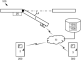
- FIG. 1 a illustrates the door operation management system connected to remote door operation management systems, via communication network, according to an aspect of the disclosure.
- FIG. 1 b illustrates the door operation management system according to an aspect of the disclosure.
- FIG. 2 a illustrates an open state of the door according to an aspect of the disclosure.
- FIG. 2 b illustrates an opening state of the door according to an aspect of the disclosure.
- FIG. 2 c illustrates a closed state of the door according to an aspect of the disclosure.
- FIG. 2 d illustrates a closing state of the door according to an aspect of the disclosure.
- FIG. 3 illustrates a flow chart of the method steps according to some aspects of the disclosure.
- FIG. 4 illustrates a computer program product according to some aspects of the disclosure.
- the functions or steps noted in the blocks can occur out of the order noted in the operational illustrations.
- two blocks shown in succession can in fact be executed substantially concurrently or the blocks can sometimes be executed in the reverse order, depending upon the functionality/acts involved.
- An object of the present disclosure is to provide system, method and computer program product for controlling the operation of a door which seek to mitigate, alleviate, or eliminate one or more of the above-identified deficiencies in the art and disadvantages singly or in any combination.
- the disclosure proposes a door operation management system 100 for controlling operation of a door 1 .
- the illustration of the door 1 in FIG. 1 a is as seen from above.
- the door 1 is arranged on e.g. a doorframe with hinges at the wall.
- the door operation management system 100 comprises at least a first movement sensor device 10 a , 10 b , 10 c arranged at the door 1 , for determining a movement of the door 1 .
- the FIG. 1 b illustrates example installation of the at least first movement sensor device 10 a , 10 b , 10 c arranged at the door 1 .
- a first movement sensor device 10 a is installed in a case 90 arranged at the door 1 as illustrated in FIG. 1 b .
- Existing cases on doors e.g. a case used for an infrared detector, can be used to receive the first movement sensor device 10 a.
- the door operation management system 100 comprises a processing circuitry 102 a , 102 b operatively connected to the at least first movement sensor device 10 a , 10 b , 10 c .
- the processing circuitry 102 a , 102 b is operatively connected to the at least first movement sensor device 10 a , 10 b , 10 c via a communication network 50 .
- the processing circuitry 102 a , 102 b is a local processing circuitry 102 a installed in the vicinity of the at least first movement sensor device 10 a , 10 b , 10 c at the door 1 . As illustrated in FIG.
- the processing circuitry 102 a is installed in the case 90 together with the first movement sensor device 10 a .
- the processing circuitry 102 a , 102 b is a remote processing circuitry 102 b connected to at least first movement sensor device 10 a , 10 b , 10 c via the communication network 50 .
- the communication network 50 is illustrated in FIG. 1 a .
- the communication network 50 is a standardized wireless wide area network such as a Global System for Mobile Communications, GSM, Extended GSM, General Packet Radio Service, GPRS, Enhanced Data Rates for GSM Evolution, EDGE, Wideband Code Division Multiple Access, WCDMA, Long Term Evolution, LTE, Narrowband-Internet of Things, NB-IoT, Third Generation, 3G, Fourth Generation, 4G, Fifth Generation 5G, Worldwide Interoperability for Microwave Access, WiMAX or Ultra Mobile Broadband, UMB or similar network.
- the communication network 50 is a standardized wireless local area network such as a Wireless Local Area Network, WLAN, BluetoothTM, ZigBee, Ultra-Wideband, Near Field Communication, NFC, Radio Frequency Identification, RFID, or similar network.
- the communication network 50 can also be a combination of both a local area network and a wide area network.
- the communication network 50 can also be wired networks.
- the communication network 50 is defined by common Internet Protocols.
- the processing circuitry 102 a , 102 b is configured to cause the door operation management system 100 to obtain at least a first sensor data dd 1 , dd 2 , dd 3 , dd 4 from the at least first movement sensor device 10 a , 10 b , 10 c and determine at least a first state st 1 , st 2 , st 3 , st 4 of the door 1 based on the at least a first sensor data dd 1 , dd 2 , dd 3 , dd 4 .
- An advantage with this solution is that by arranging the at least first movement sensor device 10 a , 10 b , 10 c on the door 1 , which requires a minimum effort, the at least first movement sensor device 10 a , 10 b , 10 c can sense any movement of the door 1 , e.g. an opening or closing of a door, which in turn results in least a first sensor data dd 1 , dd 2 , dd 3 , dd 4 that can be used for determining at least a first state st 1 , st 2 , st 3 , st 4 of the door 1 .
- the at least first sensor data dd 1 , dd 2 , dd 3 , dd 4 is at least any of acceleration data, position data or velocity data. This gives a relative movement data that can be used for determining the at least a first state st 1 , st 2 , st 3 , st 4 of the door 1 .
- the at least first movement sensor device 10 a , 10 b , 10 c is at least any of a gyroscope or an accelerometer.
- the at least first sensor data dd 1 , dd 2 , dd 3 , dd 4 is gyroscope data for determining a position of the door 1 . This has the advantage that a relative movement and also a relative position of the door 1 can be determined. In an example, when the door operation management system 100 in installed on the door 1 , a calibration of the at least first movement sensor device 10 a , 10 b , 10 c is needed in order to e.g. determine the relative position of the door 1 .
- one movement sensor device 10 a , 10 b , 10 c can provide with a plurality of sensor data dd 1 , dd 2 , dd 3 , dd 4 relating to movement.
- the at least first state st 1 , st 2 , st 3 , st 4 of the door 1 is at least any of an open state, an opening state, a closed state and a closing state.
- this gives the advantage that a plurality of states relating to a relative movement of the door 1 can be determined.
- the door 1 is a swing door and the position of the door 1 corresponds to an angle A between an open and a closed position of the swing door. This gives an indication of e.g. to what extent the door 1 is open, but also an indication of e.g. when the door 1 is about to go from an open state to a closed state, when the angle A is decreasing.
- a first movement sensor device 10 a provides with sensor data relating to gyroscope data.
- the movement sensor device 10 a provides with a relative position of the door 1 .
- an open state st 1 is determined, it is also determined that the door is open with a certain angle A in relation to a closed state, as illustrated in FIG. 2 a.
- a first movement sensor device 10 a provides with sensor data relating to acceleration data.
- the movement sensor device 10 a provides with acceleration of the door 1 , wherein the acceleration is determined to be in a direction that corresponds to an opening of a door.
- an opening state st 2 is determined, as illustrated in FIG. 2 b.
- a first movement sensor device 10 a provides with sensor data relating to acceleration data, position data and velocity data.
- the movement sensor device 10 a provides with acceleration data of the door 1 , wherein the acceleration is determined to be in a direction that corresponds to a closing of a door.
- the movement sensor device 10 a further provides with a velocity data of the door. At a certain point the velocity data is zero, meaning that the door 1 has stopped. Before the door 1 stopped, a negative acceleration, or deceleration, was detected. In the example a door was pushed to be closed, and then stopped by a door brake, to prevent damage of the door, and then closed.
- the position data verifies that the door 1 is in a closed position. In the example a closed state st 3 is determined as illustrated in FIG. 2 c.
- a first movement sensor device 10 a provides with acceleration data and position data.
- a first movement sensor device 10 a provides with acceleration data indicating an acceleration in a direction that is indicating a closing of the door 1 , and at the same time the first movement sensor device 10 a provides with position data that is indicating that the door 1 is about to be closed within a short time frame.
- a closing state st 4 is determined as illustrated in FIG. 2 d.
- the at least a first sensor data dd 1 , dd 2 , dd 3 , dd 4 obtained from the at least first movement sensor device 10 a , 10 b , 10 c , 10 d is stored together with a time stamp data in a memory 101 a , 101 b .
- the data can be used for processing at a later point of time, and i.e. that a history of the movement pattern of the door 1 over time becomes available.
- the memory 101 a , 101 b is a local memory 101 a installed in the vicinity of the door 1 .
- the memory 101 a , 101 b is a remote memory 101 b connected to the processing circuitry 102 a , 102 b via the communication network 50 .
- the stored data can be used for e.g. planning of maintenance of the door 1 . If e.g. a door is always accelerating and closing at a high speed without a brake, it can be determined that the door likely needs maintenance sooner than normal.
- the door operation management system 100 further comprises a communication module 105 configured to communicate via a communication network 50 .
- the processing circuitry 102 a , 102 b is operatively connected to the at least first movement sensor device 10 a , 10 b , 10 c and the communication module 105 .
- the processing circuitry 102 a , 102 b is further configured to cause the door operation management system 100 to send, via the communication network 50 , a door state information signal indicative of the at least first state st 1 , st 2 , st 3 , st 4 of the door 1 to at least a first remote door operation management system 200 , 300 .
- the processing circuitry 102 a , 102 b is further configured to cause the door operation management system 100 to receive, via the communication network 50 , a door state information signal indicative of the at least first state st 1 , st 2 , st 3 , st 4 of at least a remote door 2 , 3 in the at least first remote door operation management system 200 , 300 .
- the communication network 50 is a standardized wireless local area network such as a Wireless Local Area Network, WLAN, BluetoothTM, ZigBee, or similar network.
- the communication network is a so called mesh network comprising a number of nodes.
- the door operation management system 100 and the remote door operation management system 200 , 300 are linked together by a mesh network.
- the door operation management system 100 can communicate the at least first state st 1 , st 2 , st 3 , st 4 of the door 1 to other door operation management systems 200 , 300 , and receive at least first state st 1 , st 2 , st 3 , st 4 of at least a remote door 2 , 3 in the at least first remote door operation management system 200 , 300 , in order to e.g. facilitate operation of a plurality of doors, e.g. in a building or the same room, connected to the other door operation management systems 200 , 300 .
- the processing circuitry 102 a , 102 b is further configured to cause the door operation management system 100 to send, via the communication network 50 , a control signal, indicative of a close and/or open operation instruction, to at least a first door actuator device 25 configured to close and/or open the door 1 .
- a door actuator device 25 is sometimes referred to as a door operator device.
- the processing circuitry 102 a , 102 b is further configured to cause the door operation management system 100 to send, via the communication network 50 , the control signal to the at least first remote door operation management system 200 , 300 for closing and/or opening the at least remote door 2 , 3 .
- the remote door operation management systems 200 , 300 also comprising door actuator devices configured to close and/or open the remote doors 2 , 3 of the remote door operation management systems 200 , 300 .
- the door operation management system 100 is connectable to a battery power source and comprised in a case 90 made of a material that is not blocking radio frequency waves, configured to be arranged on the door 1 .
- a battery power source is also comprised in the case 90 , which makes the door operation management system 100 very easy to install.
- the case 90 is attached in the door as illustrate din FIG. 1 b.
- the disclosure further proposes a method for controlling operation of a door 1 .
- the method comprising the step of S 1 obtaining at least a first sensor data dd 1 , dd 2 , dd 3 , dd 4 from the at least first movement sensor device 10 a , 10 b , 10 c arranged at a door 1 and the step of S 2 determining at least a first state st 1 , st 2 , st 3 , st 4 of the door 1 based on the at least a first sensor data dd 1 , dd 2 , dd 3 , dd 4 .
- An advantage with this solution is that by arranging the at least first movement sensor device 10 a , 10 b , 10 c on the door 1 , which requires a minimum effort, the at least first movement sensor device 10 a , 10 b , 10 c can sense any movement of the door 1 , e.g. an opening or closing of a door, which in turn results in least a first sensor data dd 1 , dd 2 , dd 3 , dd 4 that can be used for determining at least a first state st 1 , st 2 , st 3 , st 4 of the door 1 .
- the method further comprising the step of S 3 sending, via a communication network 50 , a door state information signal indicative of the at least first state st 1 , st 2 , st 3 , st 4 of the door 1 to at least a first remote door operation management system 200 , 300 .
- the method further comprising the step of S 4 receiving, via the communication network 50 , a door state information signal indicative of the at least first state st 1 , st 2 , st 3 , st 4 of at least a remote door 2 , 3 in the at least first remote door operation management system 200 , 300 .
- the door operation management system 100 can communicate the at least first state st 1 , st 2 , st 3 , st 4 of the door 1 to other door operation management systems 200 , 300 , and receive at least first state st 1 , st 2 , st 3 , st 4 of at least a remote door 2 , 3 in the at least first remote door operation management system 200 , 300 , in order to e.g. facilitate operation of a plurality of doors, e.g. in a building or the same room, connected to the other door operation management systems 200 , 300 .
- the method further comprising the step of S 5 sending, via the communication network 50 , a control signal, indicative of a close and/or open operation instruction, to at least a first door actuator device 25 configured to close and/or open the door 1 and/or the step of S 6 sending, via the communication network 50 , the control signal to the at least first remote door operation management system 200 , 300 for closing and/or opening the at least remote door 2 , 3 .
- a control signal indicative of a close and/or open operation instruction
- the control signal to the at least first remote door operation management system 200 , 300 for closing and/or opening the at least remote door 2 , 3 .
- the disclosure further proposes a computer program product comprising a non-transitory computer readable medium, having thereon a computer program comprising program instructions, the computer program being loadable into a processing circuitry and configured to cause execution of the method when the computer program is run by the at least one processing circuitry.
- the disclosure further proposes, as illustrated in FIG. 4 , a computer program product 500 comprising a non-transitory computer readable medium, having thereon a computer program comprising program instructions, the computer program being loadable into a processing circuitry 102 a , 102 b and configured to cause execution of the method when the computer program is run by the at least one processing circuitry 102 a , 102 b.
- door operation management system 100 is configured to carry out any or more of the aspects of the described method. According to an aspect of the disclosure, the method is carried out by instructions in a software program that is downloaded and run in the vehicle window control system 100 .
Landscapes
- Engineering & Computer Science (AREA)
- Computer Networks & Wireless Communication (AREA)
- Physics & Mathematics (AREA)
- General Physics & Mathematics (AREA)
- General Engineering & Computer Science (AREA)
- Automation & Control Theory (AREA)
- Power-Operated Mechanisms For Wings (AREA)
Abstract
Description
Claims (12)
Applications Claiming Priority (3)
| Application Number | Priority Date | Filing Date | Title |
|---|---|---|---|
| SE1930199-3 | 2019-06-17 | ||
| SE1930199 | 2019-06-17 | ||
| PCT/EP2020/065895 WO2020254141A1 (en) | 2019-06-17 | 2020-06-09 | A door operation management system |
Publications (2)
| Publication Number | Publication Date |
|---|---|
| US20220307317A1 US20220307317A1 (en) | 2022-09-29 |
| US12221822B2 true US12221822B2 (en) | 2025-02-11 |
Family
ID=71078528
Family Applications (1)
| Application Number | Title | Priority Date | Filing Date |
|---|---|---|---|
| US17/616,835 Active 2041-08-31 US12221822B2 (en) | 2019-06-17 | 2020-06-09 | Door operation management system |
Country Status (4)
| Country | Link |
|---|---|
| US (1) | US12221822B2 (en) |
| EP (1) | EP3983634A1 (en) |
| CN (1) | CN113906193A (en) |
| WO (1) | WO2020254141A1 (en) |
Families Citing this family (3)
| Publication number | Priority date | Publication date | Assignee | Title |
|---|---|---|---|---|
| WO2023094342A1 (en) * | 2021-11-23 | 2023-06-01 | Assa Abloy Entrance Systems Ab | A system and method for testing of a door |
| US20230212883A1 (en) * | 2022-01-06 | 2023-07-06 | Spectrum Brands, Inc. | Lockset with door open and close sensing |
| SE547422C2 (en) * | 2023-06-20 | 2025-09-23 | Assa Abloy Ab | Determining a state of a door |
Citations (17)
| Publication number | Priority date | Publication date | Assignee | Title |
|---|---|---|---|---|
| JP2003162775A (en) | 2001-11-27 | 2003-06-06 | Santekku:Kk | System for monitoring building security |
| US20040140782A1 (en) | 2002-07-09 | 2004-07-22 | Junichiro Okabe | Door sensor and door equipped with such door sensor |
| CN101246356A (en) | 2007-02-05 | 2008-08-20 | Lg电子株式会社 | Building management system and its operation control method |
| EP1970516A2 (en) | 2007-03-15 | 2008-09-17 | BALLAN S.p.A. | Device for controlling the safety of a frame during its movement |
| US20100115853A1 (en) | 2008-11-12 | 2010-05-13 | Globe Motors, Inc. | Method of controlling an automatic door system |
| WO2013177443A1 (en) | 2012-05-23 | 2013-11-28 | Ingersoll-Rand Company | Door lock sensor and alarm |
| DE202014001263U1 (en) | 2014-02-11 | 2014-02-24 | Pepperl + Fuchs Gmbh | Device for determining an opening angle of a door leaf and optical sensor |
| EP2770486A2 (en) | 2013-02-21 | 2014-08-27 | Dale Read | Sensing device |
| US20150027057A1 (en) | 2013-07-26 | 2015-01-29 | Google Inc. | Door State Sensor |
| WO2015051942A1 (en) | 2013-10-07 | 2015-04-16 | Robert Bosch Gmbh | Device and method for determining a state of an object which is to be monitored |
| US20170162012A1 (en) * | 2015-12-07 | 2017-06-08 | Samsung Electronics Co., Ltd. | Electronic apparatus and method for determining states of door thereof |
| WO2017097771A1 (en) | 2015-12-10 | 2017-06-15 | Assa Abloy Ab | Detecting position of a barrier |
| CN106968547A (en) | 2017-05-08 | 2017-07-21 | 中山蓝网物联技术有限公司 | Automatic door opener with self-locking and wireless communication functions |
| US20170260783A1 (en) * | 2016-03-10 | 2017-09-14 | At&T Intellectual Property I, L.P. | Hinge |
| US20180082503A1 (en) * | 2016-09-20 | 2018-03-22 | Schlage Lock Company Llc | Networked door closer and auto-operator |
| US20190019381A1 (en) | 2017-07-13 | 2019-01-17 | Invoxia | Method and Device for Door Monitoring and Door Monitoring System Including Such a Device |
| US10204466B1 (en) | 2018-02-14 | 2019-02-12 | Nortek Security & Control Llc | Continuous calibration of a control device |
Family Cites Families (1)
| Publication number | Priority date | Publication date | Assignee | Title |
|---|---|---|---|---|
| DE602004025107D1 (en) * | 2003-06-16 | 2010-03-04 | Secuman B V | SENSOR ARRANGEMENTS, SYSTEMS AND AUTOMATIC DOOR OPENERS CONCERNING PROCEDURES |
-
2020
- 2020-06-09 US US17/616,835 patent/US12221822B2/en active Active
- 2020-06-09 CN CN202080040821.1A patent/CN113906193A/en active Pending
- 2020-06-09 EP EP20731857.7A patent/EP3983634A1/en active Pending
- 2020-06-09 WO PCT/EP2020/065895 patent/WO2020254141A1/en not_active Ceased
Patent Citations (18)
| Publication number | Priority date | Publication date | Assignee | Title |
|---|---|---|---|---|
| JP2003162775A (en) | 2001-11-27 | 2003-06-06 | Santekku:Kk | System for monitoring building security |
| US20040140782A1 (en) | 2002-07-09 | 2004-07-22 | Junichiro Okabe | Door sensor and door equipped with such door sensor |
| CN101246356A (en) | 2007-02-05 | 2008-08-20 | Lg电子株式会社 | Building management system and its operation control method |
| EP1970516A2 (en) | 2007-03-15 | 2008-09-17 | BALLAN S.p.A. | Device for controlling the safety of a frame during its movement |
| US20100115853A1 (en) | 2008-11-12 | 2010-05-13 | Globe Motors, Inc. | Method of controlling an automatic door system |
| WO2013177443A1 (en) | 2012-05-23 | 2013-11-28 | Ingersoll-Rand Company | Door lock sensor and alarm |
| EP2770486A2 (en) | 2013-02-21 | 2014-08-27 | Dale Read | Sensing device |
| US20150027057A1 (en) | 2013-07-26 | 2015-01-29 | Google Inc. | Door State Sensor |
| WO2015051942A1 (en) | 2013-10-07 | 2015-04-16 | Robert Bosch Gmbh | Device and method for determining a state of an object which is to be monitored |
| CN105612565A (en) | 2013-10-07 | 2016-05-25 | 罗伯特·博世有限公司 | Apparatus and method for determining the state of an object to be monitored |
| DE202014001263U1 (en) | 2014-02-11 | 2014-02-24 | Pepperl + Fuchs Gmbh | Device for determining an opening angle of a door leaf and optical sensor |
| US20170162012A1 (en) * | 2015-12-07 | 2017-06-08 | Samsung Electronics Co., Ltd. | Electronic apparatus and method for determining states of door thereof |
| WO2017097771A1 (en) | 2015-12-10 | 2017-06-15 | Assa Abloy Ab | Detecting position of a barrier |
| US20170260783A1 (en) * | 2016-03-10 | 2017-09-14 | At&T Intellectual Property I, L.P. | Hinge |
| US20180082503A1 (en) * | 2016-09-20 | 2018-03-22 | Schlage Lock Company Llc | Networked door closer and auto-operator |
| CN106968547A (en) | 2017-05-08 | 2017-07-21 | 中山蓝网物联技术有限公司 | Automatic door opener with self-locking and wireless communication functions |
| US20190019381A1 (en) | 2017-07-13 | 2019-01-17 | Invoxia | Method and Device for Door Monitoring and Door Monitoring System Including Such a Device |
| US10204466B1 (en) | 2018-02-14 | 2019-02-12 | Nortek Security & Control Llc | Continuous calibration of a control device |
Non-Patent Citations (3)
| Title |
|---|
| Chinese Office Action in 2020800408211, dated Feb. 14, 2023. |
| International Search Report in PCT/EP2020/065895 mailed Aug. 25, 2020. |
| Swedish Search Report for 1930199-3 mailed Jan. 27, 2020. |
Also Published As
| Publication number | Publication date |
|---|---|
| WO2020254141A9 (en) | 2021-03-18 |
| EP3983634A1 (en) | 2022-04-20 |
| WO2020254141A1 (en) | 2020-12-24 |
| US20220307317A1 (en) | 2022-09-29 |
| CN113906193A (en) | 2022-01-07 |
Similar Documents
| Publication | Publication Date | Title |
|---|---|---|
| US10956876B2 (en) | Connected entrance system | |
| US12221822B2 (en) | Door operation management system | |
| EP3303747B1 (en) | Method for monitoring a position and a displacement of a door closer assembly | |
| KR102746719B1 (en) | Door Operator | |
| EP3458667B1 (en) | Door closer communication | |
| US20160348398A1 (en) | Door improvements and data mining via accelerometer and magnetometer electronic component | |
| US12499716B2 (en) | System and method for controlling the operation of a door | |
| US9683400B2 (en) | Vehicle window management | |
| US11028633B2 (en) | Automatic control of a movable barrier | |
| US10748394B1 (en) | Sensor for barrier | |
| US20240287843A1 (en) | A Door Operation Support System and Method for Predicting Maintenance | |
| US20250265914A1 (en) | A system and a method for collision and intrusion detection of a door | |
| JP6054911B2 (en) | Information processing system, information processing apparatus, state detection method, and program | |
| AU2024278926A1 (en) | A door control system and method for safe configuration of the operation of a door | |
| WO2023094342A1 (en) | A system and method for testing of a door | |
| JP2012243248A (en) | Entry and exit management system |
Legal Events
| Date | Code | Title | Description |
|---|---|---|---|
| AS | Assignment |
Owner name: ASSA ABLOY ENTRANCE SYSTEMS AB, SWEDEN Free format text: ASSIGNMENT OF ASSIGNORS INTEREST;ASSIGNOR:SODERQVIST, SVEN-GUNNAR;REEL/FRAME:058309/0272 Effective date: 20210915 |
|
| FEPP | Fee payment procedure |
Free format text: ENTITY STATUS SET TO UNDISCOUNTED (ORIGINAL EVENT CODE: BIG.); ENTITY STATUS OF PATENT OWNER: LARGE ENTITY |
|
| STPP | Information on status: patent application and granting procedure in general |
Free format text: DOCKETED NEW CASE - READY FOR EXAMINATION |
|
| STPP | Information on status: patent application and granting procedure in general |
Free format text: NON FINAL ACTION MAILED |
|
| STPP | Information on status: patent application and granting procedure in general |
Free format text: FINAL REJECTION MAILED |
|
| STPP | Information on status: patent application and granting procedure in general |
Free format text: ADVISORY ACTION MAILED |
|
| STPP | Information on status: patent application and granting procedure in general |
Free format text: DOCKETED NEW CASE - READY FOR EXAMINATION |
|
| STPP | Information on status: patent application and granting procedure in general |
Free format text: NOTICE OF ALLOWANCE MAILED -- APPLICATION RECEIVED IN OFFICE OF PUBLICATIONS |
|
| STPP | Information on status: patent application and granting procedure in general |
Free format text: PUBLICATIONS -- ISSUE FEE PAYMENT VERIFIED |
|
| STCF | Information on status: patent grant |
Free format text: PATENTED CASE |