US12221408B1 - Photocatalytic reduction of carbon dioxide using Fe2TiO5 nanosheets - Google Patents
Photocatalytic reduction of carbon dioxide using Fe2TiO5 nanosheets Download PDFInfo
- Publication number
- US12221408B1 US12221408B1 US18/786,055 US202418786055A US12221408B1 US 12221408 B1 US12221408 B1 US 12221408B1 US 202418786055 A US202418786055 A US 202418786055A US 12221408 B1 US12221408 B1 US 12221408B1
- Authority
- US
- United States
- Prior art keywords
- catalyst
- tio
- nanosheets
- carbon dioxide
- hours
- Prior art date
- Legal status (The legal status is an assumption and is not a legal conclusion. Google has not performed a legal analysis and makes no representation as to the accuracy of the status listed.)
- Active
Links
- CURLTUGMZLYLDI-UHFFFAOYSA-N Carbon dioxide Chemical compound O=C=O CURLTUGMZLYLDI-UHFFFAOYSA-N 0.000 title claims abstract description 101
- 239000001569 carbon dioxide Substances 0.000 title claims abstract description 77
- 229910002092 carbon dioxide Inorganic materials 0.000 title claims abstract description 77
- 239000002135 nanosheet Substances 0.000 title claims abstract description 75
- 230000009467 reduction Effects 0.000 title description 17
- 230000001699 photocatalysis Effects 0.000 title description 12
- 229910003079 TiO5 Inorganic materials 0.000 claims abstract description 77
- 239000003054 catalyst Substances 0.000 claims abstract description 59
- 238000000034 method Methods 0.000 claims abstract description 55
- 239000012084 conversion product Substances 0.000 claims abstract description 15
- 230000001678 irradiating effect Effects 0.000 claims abstract description 12
- XEEYBQQBJWHFJM-UHFFFAOYSA-N iron Substances [Fe] XEEYBQQBJWHFJM-UHFFFAOYSA-N 0.000 claims description 93
- LCGLNKUTAGEVQW-UHFFFAOYSA-N Dimethyl ether Chemical compound COC LCGLNKUTAGEVQW-UHFFFAOYSA-N 0.000 claims description 60
- OKKJLVBELUTLKV-UHFFFAOYSA-N Methanol Chemical compound OC OKKJLVBELUTLKV-UHFFFAOYSA-N 0.000 claims description 56
- GWEVSGVZZGPLCZ-UHFFFAOYSA-N Titan oxide Chemical compound O=[Ti]=O GWEVSGVZZGPLCZ-UHFFFAOYSA-N 0.000 claims description 46
- 238000006243 chemical reaction Methods 0.000 claims description 26
- 239000000203 mixture Substances 0.000 claims description 18
- VXUYXOFXAQZZMF-UHFFFAOYSA-N titanium(IV) isopropoxide Chemical compound CC(C)O[Ti](OC(C)C)(OC(C)C)OC(C)C VXUYXOFXAQZZMF-UHFFFAOYSA-N 0.000 claims description 12
- 238000010438 heat treatment Methods 0.000 claims description 9
- 239000002904 solvent Substances 0.000 claims description 8
- 239000000725 suspension Substances 0.000 claims description 8
- 229910052742 iron Inorganic materials 0.000 claims description 7
- 239000002244 precipitate Substances 0.000 claims description 7
- 239000010936 titanium Substances 0.000 claims description 7
- 229910052719 titanium Inorganic materials 0.000 claims description 7
- 239000007864 aqueous solution Substances 0.000 claims description 6
- 238000001354 calcination Methods 0.000 claims description 6
- 150000002505 iron Chemical class 0.000 claims description 5
- JEIPFZHSYJVQDO-UHFFFAOYSA-N iron(III) oxide Inorganic materials O=[Fe]O[Fe]=O JEIPFZHSYJVQDO-UHFFFAOYSA-N 0.000 claims description 5
- 239000002245 particle Substances 0.000 claims description 5
- 229910052760 oxygen Inorganic materials 0.000 claims description 4
- 238000002835 absorbance Methods 0.000 claims description 3
- 238000002156 mixing Methods 0.000 claims description 3
- XLYOFNOQVPJJNP-UHFFFAOYSA-N water Substances O XLYOFNOQVPJJNP-UHFFFAOYSA-N 0.000 description 18
- 239000011941 photocatalyst Substances 0.000 description 16
- 238000006722 reduction reaction Methods 0.000 description 16
- 229910001868 water Inorganic materials 0.000 description 14
- 238000004519 manufacturing process Methods 0.000 description 10
- 239000000047 product Substances 0.000 description 9
- CSCPPACGZOOCGX-UHFFFAOYSA-N Acetone Chemical compound CC(C)=O CSCPPACGZOOCGX-UHFFFAOYSA-N 0.000 description 6
- XEKOWRVHYACXOJ-UHFFFAOYSA-N Ethyl acetate Chemical compound CCOC(C)=O XEKOWRVHYACXOJ-UHFFFAOYSA-N 0.000 description 6
- KFZMGEQAYNKOFK-UHFFFAOYSA-N Isopropanol Chemical group CC(C)O KFZMGEQAYNKOFK-UHFFFAOYSA-N 0.000 description 6
- 239000007789 gas Substances 0.000 description 6
- 230000007246 mechanism Effects 0.000 description 6
- OKTJSMMVPCPJKN-UHFFFAOYSA-N Carbon Chemical compound [C] OKTJSMMVPCPJKN-UHFFFAOYSA-N 0.000 description 5
- LFQSCWFLJHTTHZ-UHFFFAOYSA-N Ethanol Chemical compound CCO LFQSCWFLJHTTHZ-UHFFFAOYSA-N 0.000 description 5
- 229910052799 carbon Inorganic materials 0.000 description 5
- 238000000445 field-emission scanning electron microscopy Methods 0.000 description 5
- VCJMYUPGQJHHFU-UHFFFAOYSA-N iron(3+);trinitrate Chemical compound [Fe+3].[O-][N+]([O-])=O.[O-][N+]([O-])=O.[O-][N+]([O-])=O VCJMYUPGQJHHFU-UHFFFAOYSA-N 0.000 description 5
- 239000002086 nanomaterial Substances 0.000 description 5
- 230000008569 process Effects 0.000 description 5
- 238000001878 scanning electron micrograph Methods 0.000 description 5
- IJGRMHOSHXDMSA-UHFFFAOYSA-N Atomic nitrogen Chemical compound N#N IJGRMHOSHXDMSA-UHFFFAOYSA-N 0.000 description 4
- RTAQQCXQSZGOHL-UHFFFAOYSA-N Titanium Chemical compound [Ti] RTAQQCXQSZGOHL-UHFFFAOYSA-N 0.000 description 4
- 238000002173 high-resolution transmission electron microscopy Methods 0.000 description 4
- 239000001257 hydrogen Substances 0.000 description 4
- 229910052739 hydrogen Inorganic materials 0.000 description 4
- 230000031700 light absorption Effects 0.000 description 4
- VNWKTOKETHGBQD-UHFFFAOYSA-N methane Chemical compound C VNWKTOKETHGBQD-UHFFFAOYSA-N 0.000 description 4
- -1 nanoblocks Substances 0.000 description 4
- 238000007540 photo-reduction reaction Methods 0.000 description 4
- 238000004098 selected area electron diffraction Methods 0.000 description 4
- 238000003756 stirring Methods 0.000 description 4
- WEVYAHXRMPXWCK-UHFFFAOYSA-N Acetonitrile Chemical compound CC#N WEVYAHXRMPXWCK-UHFFFAOYSA-N 0.000 description 3
- UHOVQNZJYSORNB-UHFFFAOYSA-N Benzene Chemical compound C1=CC=CC=C1 UHOVQNZJYSORNB-UHFFFAOYSA-N 0.000 description 3
- YMWUJEATGCHHMB-UHFFFAOYSA-N Dichloromethane Chemical compound ClCCl YMWUJEATGCHHMB-UHFFFAOYSA-N 0.000 description 3
- RTZKZFJDLAIYFH-UHFFFAOYSA-N Diethyl ether Chemical compound CCOCC RTZKZFJDLAIYFH-UHFFFAOYSA-N 0.000 description 3
- ZMXDDKWLCZADIW-UHFFFAOYSA-N N,N-Dimethylformamide Chemical compound CN(C)C=O ZMXDDKWLCZADIW-UHFFFAOYSA-N 0.000 description 3
- YXFVVABEGXRONW-UHFFFAOYSA-N Toluene Chemical compound CC1=CC=CC=C1 YXFVVABEGXRONW-UHFFFAOYSA-N 0.000 description 3
- 230000032900 absorption of visible light Effects 0.000 description 3
- 238000004458 analytical method Methods 0.000 description 3
- QVGXLLKOCUKJST-UHFFFAOYSA-N atomic oxygen Chemical compound [O] QVGXLLKOCUKJST-UHFFFAOYSA-N 0.000 description 3
- 230000015572 biosynthetic process Effects 0.000 description 3
- 238000005119 centrifugation Methods 0.000 description 3
- 239000013078 crystal Substances 0.000 description 3
- 239000012153 distilled water Substances 0.000 description 3
- 230000002708 enhancing effect Effects 0.000 description 3
- 239000000446 fuel Substances 0.000 description 3
- 230000006872 improvement Effects 0.000 description 3
- 239000000463 material Substances 0.000 description 3
- 239000001301 oxygen Substances 0.000 description 3
- 239000012071 phase Substances 0.000 description 3
- 239000004065 semiconductor Substances 0.000 description 3
- 238000001228 spectrum Methods 0.000 description 3
- 238000012546 transfer Methods 0.000 description 3
- IAZDPXIOMUYVGZ-UHFFFAOYSA-N Dimethylsulphoxide Chemical compound CS(C)=O IAZDPXIOMUYVGZ-UHFFFAOYSA-N 0.000 description 2
- PMVSDNDAUGGCCE-TYYBGVCCSA-L Ferrous fumarate Chemical compound [Fe+2].[O-]C(=O)\C=C\C([O-])=O PMVSDNDAUGGCCE-TYYBGVCCSA-L 0.000 description 2
- UFHFLCQGNIYNRP-UHFFFAOYSA-N Hydrogen Chemical compound [H][H] UFHFLCQGNIYNRP-UHFFFAOYSA-N 0.000 description 2
- LRHPLDYGYMQRHN-UHFFFAOYSA-N N-Butanol Chemical compound CCCCO LRHPLDYGYMQRHN-UHFFFAOYSA-N 0.000 description 2
- 238000003917 TEM image Methods 0.000 description 2
- WYURNTSHIVDZCO-UHFFFAOYSA-N Tetrahydrofuran Chemical compound C1CCOC1 WYURNTSHIVDZCO-UHFFFAOYSA-N 0.000 description 2
- 238000002441 X-ray diffraction Methods 0.000 description 2
- 238000010521 absorption reaction Methods 0.000 description 2
- 238000000862 absorption spectrum Methods 0.000 description 2
- 238000013459 approach Methods 0.000 description 2
- 230000008901 benefit Effects 0.000 description 2
- 238000012512 characterization method Methods 0.000 description 2
- 150000001875 compounds Chemical class 0.000 description 2
- 230000008878 coupling Effects 0.000 description 2
- 238000010168 coupling process Methods 0.000 description 2
- 238000005859 coupling reaction Methods 0.000 description 2
- 239000008367 deionised water Substances 0.000 description 2
- 229910021641 deionized water Inorganic materials 0.000 description 2
- 238000013461 design Methods 0.000 description 2
- 238000011161 development Methods 0.000 description 2
- 238000009826 distribution Methods 0.000 description 2
- 230000000694 effects Effects 0.000 description 2
- 230000002349 favourable effect Effects 0.000 description 2
- 235000013924 ferrous gluconate Nutrition 0.000 description 2
- 239000004222 ferrous gluconate Substances 0.000 description 2
- 150000002431 hydrogen Chemical class 0.000 description 2
- 238000001027 hydrothermal synthesis Methods 0.000 description 2
- 238000011835 investigation Methods 0.000 description 2
- RBTARNINKXHZNM-UHFFFAOYSA-K iron trichloride Chemical compound Cl[Fe](Cl)Cl RBTARNINKXHZNM-UHFFFAOYSA-K 0.000 description 2
- VRIVJOXICYMTAG-IYEMJOQQSA-L iron(ii) gluconate Chemical compound [Fe+2].OC[C@@H](O)[C@@H](O)[C@H](O)[C@@H](O)C([O-])=O.OC[C@@H](O)[C@@H](O)[C@H](O)[C@@H](O)C([O-])=O VRIVJOXICYMTAG-IYEMJOQQSA-L 0.000 description 2
- BDAGIHXWWSANSR-UHFFFAOYSA-N methanoic acid Natural products OC=O BDAGIHXWWSANSR-UHFFFAOYSA-N 0.000 description 2
- 229910052757 nitrogen Inorganic materials 0.000 description 2
- 230000003287 optical effect Effects 0.000 description 2
- 230000003647 oxidation Effects 0.000 description 2
- 238000007254 oxidation reaction Methods 0.000 description 2
- 230000037361 pathway Effects 0.000 description 2
- 230000001443 photoexcitation Effects 0.000 description 2
- 238000010926 purge Methods 0.000 description 2
- 239000000376 reactant Substances 0.000 description 2
- 230000006798 recombination Effects 0.000 description 2
- 238000005215 recombination Methods 0.000 description 2
- 230000027756 respiratory electron transport chain Effects 0.000 description 2
- 229910001220 stainless steel Inorganic materials 0.000 description 2
- 239000010935 stainless steel Substances 0.000 description 2
- 238000012360 testing method Methods 0.000 description 2
- PFKAKHILNWLJRT-UHFFFAOYSA-H 2-hydroxypropane-1,2,3-tricarboxylate;iron(2+) Chemical compound [Fe+2].[Fe+2].[Fe+2].[O-]C(=O)CC(O)(CC([O-])=O)C([O-])=O.[O-]C(=O)CC(O)(CC([O-])=O)C([O-])=O PFKAKHILNWLJRT-UHFFFAOYSA-H 0.000 description 1
- OSWFIVFLDKOXQC-UHFFFAOYSA-N 4-(3-methoxyphenyl)aniline Chemical compound COC1=CC=CC(C=2C=CC(N)=CC=2)=C1 OSWFIVFLDKOXQC-UHFFFAOYSA-N 0.000 description 1
- UGFAIRIUMAVXCW-UHFFFAOYSA-N Carbon monoxide Chemical compound [O+]#[C-] UGFAIRIUMAVXCW-UHFFFAOYSA-N 0.000 description 1
- XDTMQSROBMDMFD-UHFFFAOYSA-N Cyclohexane Chemical compound C1CCCCC1 XDTMQSROBMDMFD-UHFFFAOYSA-N 0.000 description 1
- 239000004277 Ferrous carbonate Substances 0.000 description 1
- DKKCQDROTDCQOR-UHFFFAOYSA-L Ferrous lactate Chemical compound [Fe+2].CC(O)C([O-])=O.CC(O)C([O-])=O DKKCQDROTDCQOR-UHFFFAOYSA-L 0.000 description 1
- YZCKVEUIGOORGS-UHFFFAOYSA-N Hydrogen atom Chemical compound [H] YZCKVEUIGOORGS-UHFFFAOYSA-N 0.000 description 1
- 229910021575 Iron(II) bromide Inorganic materials 0.000 description 1
- 229910021577 Iron(II) chloride Inorganic materials 0.000 description 1
- 229910021579 Iron(II) iodide Inorganic materials 0.000 description 1
- 229910021578 Iron(III) chloride Inorganic materials 0.000 description 1
- 206010070834 Sensitisation Diseases 0.000 description 1
- 241001455273 Tetrapoda Species 0.000 description 1
- 238000004833 X-ray photoelectron spectroscopy Methods 0.000 description 1
- MDXRFOWKIZPNTA-UHFFFAOYSA-L butanedioate;iron(2+) Chemical compound [Fe+2].[O-]C(=O)CCC([O-])=O MDXRFOWKIZPNTA-UHFFFAOYSA-L 0.000 description 1
- 229910002091 carbon monoxide Inorganic materials 0.000 description 1
- 238000012824 chemical production Methods 0.000 description 1
- 239000007806 chemical reaction intermediate Substances 0.000 description 1
- 239000002131 composite material Substances 0.000 description 1
- 238000001816 cooling Methods 0.000 description 1
- 238000002425 crystallisation Methods 0.000 description 1
- 230000008025 crystallization Effects 0.000 description 1
- 238000010908 decantation Methods 0.000 description 1
- 238000001035 drying Methods 0.000 description 1
- 239000010411 electrocatalyst Substances 0.000 description 1
- 239000007772 electrode material Substances 0.000 description 1
- 238000004146 energy storage Methods 0.000 description 1
- 230000007613 environmental effect Effects 0.000 description 1
- 238000001704 evaporation Methods 0.000 description 1
- 230000008020 evaporation Effects 0.000 description 1
- 238000002474 experimental method Methods 0.000 description 1
- MSNWSDPPULHLDL-UHFFFAOYSA-K ferric hydroxide Chemical compound [OH-].[OH-].[OH-].[Fe+3] MSNWSDPPULHLDL-UHFFFAOYSA-K 0.000 description 1
- 229940032950 ferric sulfate Drugs 0.000 description 1
- RAQDACVRFCEPDA-UHFFFAOYSA-L ferrous carbonate Chemical compound [Fe+2].[O-]C([O-])=O RAQDACVRFCEPDA-UHFFFAOYSA-L 0.000 description 1
- 235000019268 ferrous carbonate Nutrition 0.000 description 1
- 239000011640 ferrous citrate Substances 0.000 description 1
- 235000019850 ferrous citrate Nutrition 0.000 description 1
- 239000011773 ferrous fumarate Substances 0.000 description 1
- 235000002332 ferrous fumarate Nutrition 0.000 description 1
- 229960000225 ferrous fumarate Drugs 0.000 description 1
- 229960001645 ferrous gluconate Drugs 0.000 description 1
- 235000013925 ferrous lactate Nutrition 0.000 description 1
- 239000004225 ferrous lactate Substances 0.000 description 1
- 229960001604 ferrous succinate Drugs 0.000 description 1
- 238000001914 filtration Methods 0.000 description 1
- 235000019253 formic acid Nutrition 0.000 description 1
- 239000002803 fossil fuel Substances 0.000 description 1
- 230000006870 function Effects 0.000 description 1
- 238000000769 gas chromatography-flame ionisation detection Methods 0.000 description 1
- 239000007792 gaseous phase Substances 0.000 description 1
- 239000005431 greenhouse gas Substances 0.000 description 1
- 238000005286 illumination Methods 0.000 description 1
- 239000012535 impurity Substances 0.000 description 1
- 239000011261 inert gas Substances 0.000 description 1
- 229910052500 inorganic mineral Inorganic materials 0.000 description 1
- 239000000543 intermediate Substances 0.000 description 1
- NMCUIPGRVMDVDB-UHFFFAOYSA-L iron dichloride Chemical compound Cl[Fe]Cl NMCUIPGRVMDVDB-UHFFFAOYSA-L 0.000 description 1
- 159000000014 iron salts Chemical class 0.000 description 1
- OXNSNGFUWQVOKD-UHFFFAOYSA-N iron(2+);dicyanide Chemical compound [Fe+2].N#[C-].N#[C-] OXNSNGFUWQVOKD-UHFFFAOYSA-N 0.000 description 1
- MVFCKEFYUDZOCX-UHFFFAOYSA-N iron(2+);dinitrate Chemical compound [Fe+2].[O-][N+]([O-])=O.[O-][N+]([O-])=O MVFCKEFYUDZOCX-UHFFFAOYSA-N 0.000 description 1
- OWZIYWAUNZMLRT-UHFFFAOYSA-L iron(2+);oxalate Chemical compound [Fe+2].[O-]C(=O)C([O-])=O OWZIYWAUNZMLRT-UHFFFAOYSA-L 0.000 description 1
- RUTXIHLAWFEWGM-UHFFFAOYSA-H iron(3+) sulfate Chemical compound [Fe+3].[Fe+3].[O-]S([O-])(=O)=O.[O-]S([O-])(=O)=O.[O-]S([O-])(=O)=O RUTXIHLAWFEWGM-UHFFFAOYSA-H 0.000 description 1
- LIKBJVNGSGBSGK-UHFFFAOYSA-N iron(3+);oxygen(2-) Chemical compound [O-2].[O-2].[O-2].[Fe+3].[Fe+3] LIKBJVNGSGBSGK-UHFFFAOYSA-N 0.000 description 1
- SUBFIBLJQMMKBK-UHFFFAOYSA-K iron(3+);trithiocyanate Chemical compound [Fe+3].[S-]C#N.[S-]C#N.[S-]C#N SUBFIBLJQMMKBK-UHFFFAOYSA-K 0.000 description 1
- 229910000015 iron(II) carbonate Inorganic materials 0.000 description 1
- 229910021506 iron(II) hydroxide Inorganic materials 0.000 description 1
- 229910000360 iron(III) sulfate Inorganic materials 0.000 description 1
- LNOZJRCUHSPCDZ-UHFFFAOYSA-L iron(ii) acetate Chemical compound [Fe+2].CC([O-])=O.CC([O-])=O LNOZJRCUHSPCDZ-UHFFFAOYSA-L 0.000 description 1
- GYCHYNMREWYSKH-UHFFFAOYSA-L iron(ii) bromide Chemical compound [Fe+2].[Br-].[Br-] GYCHYNMREWYSKH-UHFFFAOYSA-L 0.000 description 1
- HEQBUZNAOJCRSL-UHFFFAOYSA-N iron(ii) chromite Chemical compound [O-2].[O-2].[O-2].[Cr+3].[Fe+3] HEQBUZNAOJCRSL-UHFFFAOYSA-N 0.000 description 1
- FZGIHSNZYGFUGM-UHFFFAOYSA-L iron(ii) fluoride Chemical compound [F-].[F-].[Fe+2] FZGIHSNZYGFUGM-UHFFFAOYSA-L 0.000 description 1
- FUEZNWLRTWZOHC-UHFFFAOYSA-N iron(ii) hydride Chemical compound [FeH2] FUEZNWLRTWZOHC-UHFFFAOYSA-N 0.000 description 1
- NCNCGGDMXMBVIA-UHFFFAOYSA-L iron(ii) hydroxide Chemical compound [OH-].[OH-].[Fe+2] NCNCGGDMXMBVIA-UHFFFAOYSA-L 0.000 description 1
- BQZGVMWPHXIKEQ-UHFFFAOYSA-L iron(ii) iodide Chemical compound [Fe+2].[I-].[I-] BQZGVMWPHXIKEQ-UHFFFAOYSA-L 0.000 description 1
- QQOCLJJWXLOEJE-UHFFFAOYSA-N iron(ii) molybdate Chemical compound [Fe+2].[O-][Mo]([O-])(=O)=O QQOCLJJWXLOEJE-UHFFFAOYSA-N 0.000 description 1
- 230000007774 longterm Effects 0.000 description 1
- 239000002082 metal nanoparticle Substances 0.000 description 1
- 239000012621 metal-organic framework Substances 0.000 description 1
- 239000011707 mineral Substances 0.000 description 1
- 235000010755 mineral Nutrition 0.000 description 1
- 238000012986 modification Methods 0.000 description 1
- 230000004048 modification Effects 0.000 description 1
- 230000000877 morphologic effect Effects 0.000 description 1
- 239000002102 nanobead Substances 0.000 description 1
- 239000002127 nanobelt Substances 0.000 description 1
- 239000002159 nanocrystal Substances 0.000 description 1
- 239000002107 nanodisc Substances 0.000 description 1
- 239000002060 nanoflake Substances 0.000 description 1
- 239000002057 nanoflower Substances 0.000 description 1
- 239000011858 nanopowder Substances 0.000 description 1
- 239000002074 nanoribbon Substances 0.000 description 1
- 239000002070 nanowire Substances 0.000 description 1
- LYGJENNIWJXYER-UHFFFAOYSA-N nitromethane Chemical compound C[N+]([O-])=O LYGJENNIWJXYER-UHFFFAOYSA-N 0.000 description 1
- 229910000510 noble metal Inorganic materials 0.000 description 1
- 239000003960 organic solvent Substances 0.000 description 1
- 239000008188 pellet Substances 0.000 description 1
- 239000003208 petroleum Substances 0.000 description 1
- 238000013032 photocatalytic reaction Methods 0.000 description 1
- 239000000843 powder Substances 0.000 description 1
- RUOJZAUFBMNUDX-UHFFFAOYSA-N propylene carbonate Chemical compound CC1COC(=O)O1 RUOJZAUFBMNUDX-UHFFFAOYSA-N 0.000 description 1
- 239000010453 quartz Substances 0.000 description 1
- 238000011946 reduction process Methods 0.000 description 1
- 230000001105 regulatory effect Effects 0.000 description 1
- 238000001223 reverse osmosis Methods 0.000 description 1
- 150000003839 salts Chemical class 0.000 description 1
- 239000004576 sand Substances 0.000 description 1
- 230000008313 sensitization Effects 0.000 description 1
- 238000000926 separation method Methods 0.000 description 1
- VYPSYNLAJGMNEJ-UHFFFAOYSA-N silicon dioxide Inorganic materials O=[Si]=O VYPSYNLAJGMNEJ-UHFFFAOYSA-N 0.000 description 1
- 239000002002 slurry Substances 0.000 description 1
- 239000000243 solution Substances 0.000 description 1
- 238000000527 sonication Methods 0.000 description 1
- 238000001179 sorption measurement Methods 0.000 description 1
- 238000003860 storage Methods 0.000 description 1
- 239000000126 substance Substances 0.000 description 1
- 230000002459 sustained effect Effects 0.000 description 1
- 238000003786 synthesis reaction Methods 0.000 description 1
- PBCFLUZVCVVTBY-UHFFFAOYSA-N tantalum pentoxide Inorganic materials O=[Ta](=O)O[Ta](=O)=O PBCFLUZVCVVTBY-UHFFFAOYSA-N 0.000 description 1
- 239000008399 tap water Substances 0.000 description 1
- 235000020679 tap water Nutrition 0.000 description 1
- YLQBMQCUIZJEEH-UHFFFAOYSA-N tetrahydrofuran Natural products C=1C=COC=1 YLQBMQCUIZJEEH-UHFFFAOYSA-N 0.000 description 1
- 238000005979 thermal decomposition reaction Methods 0.000 description 1
- ZNOKGRXACCSDPY-UHFFFAOYSA-N tungsten(VI) oxide Inorganic materials O=[W](=O)=O ZNOKGRXACCSDPY-UHFFFAOYSA-N 0.000 description 1
- 230000035899 viability Effects 0.000 description 1
- 238000001429 visible spectrum Methods 0.000 description 1
- 238000005406 washing Methods 0.000 description 1
- XLOMVQKBTHCTTD-UHFFFAOYSA-N zinc oxide Inorganic materials [Zn]=O XLOMVQKBTHCTTD-UHFFFAOYSA-N 0.000 description 1
Images


Classifications
-
- C—CHEMISTRY; METALLURGY
- C07—ORGANIC CHEMISTRY
- C07C—ACYCLIC OR CARBOCYCLIC COMPOUNDS
- C07C29/00—Preparation of compounds having hydroxy or O-metal groups bound to a carbon atom not belonging to a six-membered aromatic ring
- C07C29/15—Preparation of compounds having hydroxy or O-metal groups bound to a carbon atom not belonging to a six-membered aromatic ring by reduction of oxides of carbon exclusively
- C07C29/159—Preparation of compounds having hydroxy or O-metal groups bound to a carbon atom not belonging to a six-membered aromatic ring by reduction of oxides of carbon exclusively with reducing agents other than hydrogen or hydrogen-containing gases
-
- B—PERFORMING OPERATIONS; TRANSPORTING
- B01—PHYSICAL OR CHEMICAL PROCESSES OR APPARATUS IN GENERAL
- B01J—CHEMICAL OR PHYSICAL PROCESSES, e.g. CATALYSIS OR COLLOID CHEMISTRY; THEIR RELEVANT APPARATUS
- B01J21/00—Catalysts comprising the elements, oxides, or hydroxides of magnesium, boron, aluminium, carbon, silicon, titanium, zirconium, or hafnium
- B01J21/06—Silicon, titanium, zirconium or hafnium; Oxides or hydroxides thereof
- B01J21/063—Titanium; Oxides or hydroxides thereof
-
- B—PERFORMING OPERATIONS; TRANSPORTING
- B01—PHYSICAL OR CHEMICAL PROCESSES OR APPARATUS IN GENERAL
- B01J—CHEMICAL OR PHYSICAL PROCESSES, e.g. CATALYSIS OR COLLOID CHEMISTRY; THEIR RELEVANT APPARATUS
- B01J23/00—Catalysts comprising metals or metal oxides or hydroxides, not provided for in group B01J21/00
- B01J23/70—Catalysts comprising metals or metal oxides or hydroxides, not provided for in group B01J21/00 of the iron group metals or copper
- B01J23/74—Iron group metals
- B01J23/745—Iron
-
- B—PERFORMING OPERATIONS; TRANSPORTING
- B01—PHYSICAL OR CHEMICAL PROCESSES OR APPARATUS IN GENERAL
- B01J—CHEMICAL OR PHYSICAL PROCESSES, e.g. CATALYSIS OR COLLOID CHEMISTRY; THEIR RELEVANT APPARATUS
- B01J35/00—Catalysts, in general, characterised by their form or physical properties
- B01J35/30—Catalysts, in general, characterised by their form or physical properties characterised by their physical properties
- B01J35/39—Photocatalytic properties
-
- B—PERFORMING OPERATIONS; TRANSPORTING
- B01—PHYSICAL OR CHEMICAL PROCESSES OR APPARATUS IN GENERAL
- B01J—CHEMICAL OR PHYSICAL PROCESSES, e.g. CATALYSIS OR COLLOID CHEMISTRY; THEIR RELEVANT APPARATUS
- B01J35/00—Catalysts, in general, characterised by their form or physical properties
- B01J35/40—Catalysts, in general, characterised by their form or physical properties characterised by dimensions, e.g. grain size
- B01J35/45—Nanoparticles
-
- B—PERFORMING OPERATIONS; TRANSPORTING
- B01—PHYSICAL OR CHEMICAL PROCESSES OR APPARATUS IN GENERAL
- B01J—CHEMICAL OR PHYSICAL PROCESSES, e.g. CATALYSIS OR COLLOID CHEMISTRY; THEIR RELEVANT APPARATUS
- B01J35/00—Catalysts, in general, characterised by their form or physical properties
- B01J35/50—Catalysts, in general, characterised by their form or physical properties characterised by their shape or configuration
-
- B—PERFORMING OPERATIONS; TRANSPORTING
- B01—PHYSICAL OR CHEMICAL PROCESSES OR APPARATUS IN GENERAL
- B01J—CHEMICAL OR PHYSICAL PROCESSES, e.g. CATALYSIS OR COLLOID CHEMISTRY; THEIR RELEVANT APPARATUS
- B01J37/00—Processes, in general, for preparing catalysts; Processes, in general, for activation of catalysts
- B01J37/02—Impregnation, coating or precipitation
- B01J37/03—Precipitation; Co-precipitation
-
- B—PERFORMING OPERATIONS; TRANSPORTING
- B01—PHYSICAL OR CHEMICAL PROCESSES OR APPARATUS IN GENERAL
- B01J—CHEMICAL OR PHYSICAL PROCESSES, e.g. CATALYSIS OR COLLOID CHEMISTRY; THEIR RELEVANT APPARATUS
- B01J37/00—Processes, in general, for preparing catalysts; Processes, in general, for activation of catalysts
- B01J37/08—Heat treatment
- B01J37/10—Heat treatment in the presence of water, e.g. steam
-
- C—CHEMISTRY; METALLURGY
- C07—ORGANIC CHEMISTRY
- C07C—ACYCLIC OR CARBOCYCLIC COMPOUNDS
- C07C29/00—Preparation of compounds having hydroxy or O-metal groups bound to a carbon atom not belonging to a six-membered aromatic ring
- C07C29/15—Preparation of compounds having hydroxy or O-metal groups bound to a carbon atom not belonging to a six-membered aromatic ring by reduction of oxides of carbon exclusively
-
- C—CHEMISTRY; METALLURGY
- C07—ORGANIC CHEMISTRY
- C07C—ACYCLIC OR CARBOCYCLIC COMPOUNDS
- C07C41/00—Preparation of ethers; Preparation of compounds having groups, groups or groups
- C07C41/01—Preparation of ethers
-
- B—PERFORMING OPERATIONS; TRANSPORTING
- B01—PHYSICAL OR CHEMICAL PROCESSES OR APPARATUS IN GENERAL
- B01J—CHEMICAL OR PHYSICAL PROCESSES, e.g. CATALYSIS OR COLLOID CHEMISTRY; THEIR RELEVANT APPARATUS
- B01J2235/00—Indexing scheme associated with group B01J35/00, related to the analysis techniques used to determine the catalysts form or properties
- B01J2235/15—X-ray diffraction
-
- B—PERFORMING OPERATIONS; TRANSPORTING
- B01—PHYSICAL OR CHEMICAL PROCESSES OR APPARATUS IN GENERAL
- B01J—CHEMICAL OR PHYSICAL PROCESSES, e.g. CATALYSIS OR COLLOID CHEMISTRY; THEIR RELEVANT APPARATUS
- B01J2235/00—Indexing scheme associated with group B01J35/00, related to the analysis techniques used to determine the catalysts form or properties
- B01J2235/30—Scanning electron microscopy; Transmission electron microscopy
Definitions
- the present disclosure is directed towards reducing carbon dioxide (CO 2 ), and more particularly, towards a method of reducing CO 2 using Fe 2 TiO 5 nanosheets.
- Materials employed in electrochemical reduction should be available in large quantities with significant efficiency while preserving low costs to ensure their economic viability. Furthermore, favorable properties include high CO 2 adsorption capacity, efficient charge transfer kinetics, and the ability to suppress competing reactions.
- the catalysts should exhibit long-term stability, allowing continuous CO 2 reduction under various operating conditions. To date, different electrode materials and designs have been investigated for the electrochemical reduction of CO 2 , with materials such as metal nanoparticles, metal-organic frameworks, and single-atom catalysts.
- Photocatalysts such as TiO 2 , Fe 2 O 3 , ZnO, Ta 2 O 5 and WO 3 have been developed and TiO 2 has garnered attention as a semiconductor because of its strong oxidation and reduction abilities. Additionally, TiO 2 is eco-friendly, affordable, and may be produced in diverse nanostructures using economical techniques. However, a high rate of charge recombination leads to inadequate photocatalytic capabilities. Hence, enhancing the light absorption capacity of TiO 2 to encompass the visible range of the solar spectrum can improve photocatalytic capabilities. To address this issue, several strategies have been explored, including the application of noble metals, surface sensitization to light, and the creation of carbon-based composites.
- An approach to boost TiO 2 activity under visible light involves incorporating semiconductors with a low band gap energy. This combination extends the optical absorption range into the visible portion of the solar spectrum. Iron (III) oxide (Fe 2 O 3 ), with its narrow band gap of around 1.97 electron Volts (eV) emerges as an option for this purpose.
- Iron (III) oxide (Fe 2 O 3 ) with its narrow band gap of around 1.97 electron Volts (eV) emerges as an option for this purpose.
- the development of a combined Fe 2 TiO 5 nanostructures may improve both photoactivity and selectivity when compared to only a mixture of the Fe 2 O 3 /TiO 2 materials.
- an object of the present disclosure is to develop a Fe 2 TiO 5 nanomaterial for CO 2 reduction, particularly under solar energy conditions.
- a method of reducing carbon dioxide includes contacting a catalyst and the carbon dioxide (CO 2 ) and irradiating the catalyst and the CO 2 with visible light. Further, on irradiating, the CO 2 is reduced to a conversion product.
- the catalyst includes Fe 2 TiO 5 and particles of the Fe 2 TiO 5 are in a form of nanosheets.
- the nanosheets have an average width of 200 nanometers (nm) to 800 nm, and the nanosheets form a hierarchical structure.
- the nanosheets are crystalline.
- the nanosheets have an interplanar distance of 0.3-0.4 nm.
- the nanosheets have an average length of 1 micrometers ( ⁇ m) to 3 ⁇ m.
- the catalyst includes 45 weight percentage (wt. %) to 55 wt. % Fe, 25-35 wt. % 0, and 15-25 wt. % Ti, based on a total weight of the catalyst.
- the catalyst absorbs light from 200-550 nm.
- the catalyst has a peak light absorbance from 375-425 nm.
- the catalyst has a band gap of 1.9 electron Volts (eV) to 2.2 eV.
- the catalyst does not include Fe 2 O 3 or TiO 2 .
- the carbon dioxide is in a gaseous state.
- the carbon dioxide is in an aqueous solution.
- the conversion product is at least one selected from the group consisting of methanol and dimethyl ether.
- the iriadiating is for 1 min to 10 hours.
- the visible light has a wavelength of 400-700 nm, and a power of 10-100 W.
- the conversion product is methanol
- a yield of the methanol is 120 micromoles per gram ( ⁇ mol/g) to 160 ⁇ mol/g of the catalyst after irradiating for 4 hours.
- the conversion product is dimethyl ether, and a yield of the dimethyl ether of 40-60 ⁇ mol/g of the catalyst after irradiating for 4 hours.
- the catalyst has a higher conversion to the conversion product than TiO 2 under the same conditions.
- the method includes mixing an iron salt in a solvent to form a first mixture, adding titanium isopropoxide to the first mixture to form a second mixture, and heating the second mixture in an autoclave at a temperature of 150 degrees Celsius (° C.) 200° C. for 1-24 hours to form a suspension.
- the method further includes separating a precipitate from the suspension and calcining the precipitate at a temperature of 400-800° C. for 1-24 hours to form the catalyst.
- FIG. 1 A is a flowchart illustrating a method for reducing carbon dioxide, according to certain embodiments.
- FIG. 1 B is a flowchart illustrating a method of making Fe 2 TiO 5 , according to certain embodiments.
- FIG. 2 is a schematic illustration depicting a formation process of Fe 2 TiO 5 nanosheets, according to certain embodiments.
- FIG. 3 depicts an experimental setup for photocatalytic carbon dioxide (CO 2 ) conversion with water (H 2 O), according to certain embodiments.
- FIG. 4 shows X-ray diffraction (XRD) patterns of TiO 2 and Fe 2 TiO 5 , according to certain embodiments.
- FIG. 5 A is a transmission electron microscopy (TEM) image of Fe 2 TiO 5 nanosheets, according to certain embodiments.
- FIG. 5 B is a high-resolution transmission electron microscopy (HRTEM) image depicting lattice fringes of Fe 2 TiO 5 nanosheets, according to certain embodiments.
- HRTEM transmission electron microscopy
- FIG. 5 C is an optical image depicting selected area electron diffraction (SAED) pattern of Fe 2 TiO 5 nanosheets, according to certain embodiments.
- SAED selected area electron diffraction
- FIG. 5 D is a scanning electron microscopy (SEM) image of Fe 2 TiO 5 nanosheets, according to certain embodiments.
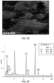
- FIG. 5 E is a field emission scanning electron microscopy (FESEM) image of Fe 2 TiO 5 nanosheets, according to certain embodiments.
- FIG. 5 F depicts an energy-dispersive X-ray (EDX) spectrum of Fe 2 TiO 5 nanosheets according to certain embodiments.
- EDX energy-dispersive X-ray
- FIG. 5 G is an SEM image of Fe 2 TiO 5 nanosheets depicting the presence of iron, according to certain embodiments.
- FIG. 5 H is an SEM image of Fe 2 TiO 5 nanosheets depicting the presence of oxygen, according to certain embodiments.
- FIG. 5 I is an SEM image of Fe 2 TiO 5 nanosheets depicting the presence of titanium, according to certain embodiments.
- FIG. 6 A shows diffuse reflectance (DR) ultra-violet (UV) visible spectra of TiO 2 and Fe 2 TO 5 nanosheets, according to certain embodiments.
- FIG. 6 B is a graph depicting band gap energy calculations from absorption spectra of Fe 2 TO 5 nanosheets, according to certain embodiments.
- FIG. 7 shows the yield of CH 3 OH and dimethyl ether (DME) over TiO 2 and Fe 2 TO 5 photocatalysts at an irradiation time of 1 hour, room temperature, and atmospheric pressure, according to certain embodiments.
- DME dimethyl ether
- FIG. 8 shows the yield of CH 3 OH and dimethyl ether (DME) with TiO 2 and Fe 2 TO 5 photocatalysts over time, according to certain embodiments.
- FIG. 9 is a schematic illustration depicting a reaction mechanism proposed for the photoreduction of CO 2 to CH 3 OH and DME over Fe 2 TO 5 nanosheets under visible light, according to certain embodiments.
- the terms “approximately,” “approximate,” “about,” and similar terms generally refer to ranges that include the identified value within a margin of 20%, 10%, or preferably 5%, and any values therebetween.
- aspects of the present disclosure are directed toward a method of reducing carbon dioxide (CO 2 ) using a Fe 2 TiO 5 nanomaterial.
- the nanomaterial of the present disclosure synthesized via a single-step hydrothermal method, functions as an efficient photocatalyst capable of responding to visible light for CO 2 conversion.
- FIG. 1 A illustrates a schematic flow chart of a method 50 of reducing carbon dioxide.
- the order in which the method 50 is described is not intended to be construed as a limitation, and any number of the described method steps can be combined in any order to implement the method 50. Additionally, individual steps may be removed or skipped from the method 50 without departing from the spirit and scope of the present disclosure.
- the method 50 includes contacting a catalyst and carbon dioxide (CO 2 ).
- the catalyst includes Fe 2 TiO 5 .
- Particles of the Fe 2 TiO 5 are in the form of nanosheets, although in some embodiments, the particles may exist in various morphological shapes, such as nanowires, nanocrystals, nanorectangles, nanotriangles, nanopentagons, nanohexagons, nanoprisms, nanodisks, nanocubes, nanoribbons, nanoblocks, nanobeads, nanotoroids, nanodiscs, nanobarrels, nanogranules, nanowhiskers, nanoflakes, nanofoils, nanopowders, nanoboxes, nanostars, tetrapods, nanobelts, nano-urchins, nanoflowers, etc. and mixtures thereof.
- the nanosheets have an average width of 200-800 nanometers (nm), preferably 250-750 nm, 300-700 nm, 350-650 nm, 400-600 nm, or 450-550 nm. In some embodiments, the nanosheets have an average length of 1-3 micrometers ( ⁇ m), preferably 1.2-2.8 ⁇ m, 1.4-2.6 ⁇ m, 1.6-2.4 ⁇ m, 1.8-2.2 ⁇ m, or about 2 ⁇ m. In some embodiments, the nanosheets form a hierarchical structure, where the nanosheets are stacked on top of one another forming a column of the nanosheets.
- the nanosheets form a hierarchical structure of two or more of the nanosheets stacked on top of one another, preferably 2 to 10,000 nanosheets, 10-1,000 or 100-500 nanosheets.
- the interplanar distance between the nanosheets is between 0.3-0.4 nm, more preferably 0.32-0.38 nm, and yet more preferably 0.35 nm.
- the columns of nanosheets are randomly oriented.
- the nanosheet columns are organized and are evenly spaced parallel to one another.
- the nanosheets are crystalline. In some embodiments, the nanosheets consist of a Fe 2 TiO 5 crystalline phase. In some embodiments, the catalyst does not include Fe 2 O 3 or TiO 2 crystalline phases.
- the Fe 2 TiO 5 catalyst includes 45-55 wt. %, more preferably 51 to 53 wt. %, and yet more preferably 52.9 wt. % Fe, 25-35 wt. %, more preferably 28 to 32 wt. %, and yet more preferably 29.7 wt. % 0, and 15-25 wt. %, more preferably 16 to 18 wt. %, and yet more preferably 17.4 wt. % Ti, based on the total weight of the catalyst.
- the catalyst is contacted with CO 2 , preferably in a reactor.
- the carbon dioxide is in a gaseous state.
- the reactor may optionally include other gases as well, such as CO or hydrogen.
- the reactor is purged with an inert gas or nitrogen to remove other gases before contacting the catalyst with the CO 2 .
- the catalyst is placed in the reactor, preferably as powdered particles, to ensure proper distribution.
- the CO 2 is flowed into the reactor at a flow rate in the range of 5-20 mL/min, preferably 6-19 mL/min, preferably 7-18 mL/min, preferably 8-15 mL/min, preferably 10-12 mL/min, preferably 10 mL/min.
- the carbon dioxide is in an aqueous solution.
- the aqueous solution may be tap water, distilled water, bi-distilled water, deionized water, deionized distilled water, reverse osmosis water, and/or some other water.
- the aqueous solution contains 0.1-100 ppm of the carbon dioxide, preferably 1-90 ppm, 10-80 ppm, 20-70 ppm, 30-60 ppm, and 40-50 ppm.
- the CO 2 in the aqueous solution is flowed into the reactor at a flow rate in the range of 1-100 mL/min, preferably 10-90 mL/min, preferably 20-80 mL/min, preferably 30-70 mL/min, preferably 40-60 mL/min, preferably 50 mL/min.
- the reactor is at least one selected from the group consisting of a fixed-bed reactor, a trickle-bed reactor, a moving bed reactor, a rotating bed reactor, a fluidized bed reactor, and a slurry reactor.
- the reactor is a fixed-bed reactor in the form of a cylindrical reactor, which includes a top portion, a cylindrical body portion, a bottom portion, and a housing.
- the term ‘fixed-bed reactor’ refers to the cylindrical tube filled with catalyst pellets with reactants flowing through the bed and being converted into products.
- method 50 includes irradiating the catalyst and the carbon dioxide with light.
- the steps 52 and 54 may occur simultaneously.
- the light is visible light.
- visible light refers to light having a wavelength ⁇ greater than 400 nm, preferably 400-700 nm, preferably 500-600 nm, preferably 510-590 nm, preferably 520-580 nm, preferably 530-580 nm, preferably 550-580 nm, preferably 570-590 nm, preferably 580-590 nm, preferably 587 nm.
- the irradiation process is carried out under visible light at a power of 10-100 watts (W), preferably 20-90 W, preferably 30-80 W, preferably 40-60 W, and yet more preferably 50 W for 1 minute to 10 hours, preferably 1 to 9 hours, 2 to 8 hours, 3 to 7 hours, 4 to 6 hours, or 5 hours.
- W 10-100 watts
- the catalyst has a band gap of 1.9-2.2 electron volts (eV), preferably 1.95-2.15 eV, 2.0-2.1 eV, or about 2.05 eV.
- the catalyst absorbs light from 200 to 550 nm, preferably 250-500 nm, 300-450 nm, or 350-400 nm, with a peak light absorbance in the range of 375 to 425 nm or about 400 nm.
- the addition of the Fe into the crystal structure improves the absorption of visible light in comparison to TiO 2 alone which does not absorb light after about 400 nm.
- the conversion product is selected from the group consisting of methane, hydrogen, carbon monoxide, methanol and dimethyl ether.
- the hydrogen source for the photoreduction process may be water, hydrogen, or other appropriate sources that produce atomic hydrogen known in the art.
- the yield of methanol is 120-160 ⁇ mol per gram of the catalyst, more preferably 140-155 ⁇ mol per gram of the catalyst, and yet more preferably 149.5 ⁇ mol per gram of the catalyst after irradiation for 4 hours, and the yield of the dimethyl ether is about 40-60 ⁇ mol per gram of the catalyst after irradiation for 4 hours.
- the conversion reaction continues for at least 4 hours, preferably 4-24 hours, 5-20 hours, or 10-15 hours. In other words, the catalyst is stable and does not degrade over such time period.
- the catalyst and carbon dioxide are contacted and not irradiated, the conversion products are not generated.
- the catalyst acts as a photocatalyst and is not activated without the absorption of light.
- the Fe 2 TiO 5 catalyst has a higher conversion to the conversion product than TiO 2 under the same conditions. While not wishing to be bound to a single theory, this improvement is ascribed to the effective absorption of visible light by the Fe 2 TiO 5 , proficient charge transfer characteristics, and heightened electron mobility achieved through the coupling of iron with titanium and the formation of a hierarchical structure.
- FIG. 1 B illustrates a schematic flow chart of a method 70 of making the Fe 2 TiO 5 .
- the order in which the method 70 is described is not intended to be construed as a limitation, and any number of the described method steps can be combined in any order to implement the method 70. Additionally, individual steps may be removed or skipped from the method 70 without departing from the spirit and scope of the present disclosure.
- the method 70 includes mixing an iron salt in a solvent to form a first mixture.
- iron salts include iron (II) acetate, iron (II) bromide, iron (II) carbonate, iron (II) chloride, iron (II) chromite, iron (II) citrate, iron (II) cyanide, iron (II) fluoride, iron (II) fumarate, iron (II) gluconate, iron (II) hydride, iron (II) hydroxide, iron (II) iodide, iron (II) lactate, iron (II) molybdate, iron (II) nitrate, iron (II) oxalate, iron (III) chloride, iron (III) thiocyanate, ferric sulfate, ferrous fumarate, ferrous gluconate, ferrous succinate, iron (III) hydroxide, iron (III) nitrate.
- the iron salt is iron (III) nitrate.
- the solvent is an organic solvent.
- the solvent may include, but is not limited to, tetrahydrofuran, ethyl acetate, dimethylformamide, acetonitrile, acetone, dimethyl sulfoxide, nitromethane, propylene carbonate, ethanol, formic acid, n-butanol, methanol, or any combination thereof.
- the solvent may include benzene, cyclohexane, ethanol, methanol, acetone, ethyl acetate, dichloromethane, toluene, and diethyl ether.
- the solvent is isopropanol.
- the iron salt may be mixed with the solvent via stirring/swirling/sonication/a combination of these methods to form the first mixture.
- the method 70 includes adding titanium isopropoxide to the first mixture to form a second mixture.
- Titanium isopropoxide can be added dropwise to the first mixture.
- the titanium isopropoxide can be added to the first mixture by any method used or known in the art.
- the method 70 includes heating the second mixture in an autoclave, preferably a Teflon-lined stainless-steel autoclave, at a temperature of 150-200° C., more preferably 155 to 165° C., and more preferably 160° C. for 1-24 hours, more preferably 10 to 14 hours, and more preferably 12 hours to form a suspension.
- the heating can be performed by using heating appliances such as ovens, microwaves, autoclaves, hot plates, heating mantles and tapes, oil baths, salt baths, sand baths, air baths, hot-tube furnaces, and hot-air guns.
- method 70 includes separating a precipitate from the suspension.
- the separation may be performed by methods including filtration, decantation, evaporation, and centrifugation.
- the precipitate is separated from the suspension using centrifugation.
- the method 70 includes calcining the precipitate at a temperature of 400-800° C., more preferably 550 to 650° C., and more preferably 600° C. for 1-24 hours, more preferably 1.5 to 5 hours, and more preferably 2 hours to form the catalyst.
- the calcination is carried out by heating it to a high temperature under a restricted supply of ambient oxygen. This is performed to remove impurities or volatile substances and to incur thermal decomposition.
- the calcination is carried out in a furnace, preferably equipped with a temperature control system, which may provide a heating rate of up to 50° C./min, preferably up to 40° C./min, preferably up to 30° C./min, preferably up to 20° C./min, preferably up to 10° C./min, preferably up to 5° C./min, to form the catalyst.
- a temperature control system which may provide a heating rate of up to 50° C./min, preferably up to 40° C./min, preferably up to 30° C./min, preferably up to 20° C./min, preferably up to 10° C./min, preferably up to 5° C./min, to form the catalyst.
- the as-prepared photocatalysts were tested for photocatalytic conversion of CO 2 in a gaseous phase fixed-bed photoreactor, as shown in FIG. 3 .
- 150 milligrams (mg) of powder photocatalysts were dispersed at the bottom of the photoreactor to ensure proper distribution.
- the reactor Prior to introducing reactant gases, the reactor underwent nitrogen purging to eliminate other gases.
- High purity compressed CO 2 regulated by a mass flow controller, was passed through a water saturator for moisture carriage.
- X-ray diffraction (XRD) analysis was employed to investigate the crystal phase and structure of photocatalysts, as shown in FIG. 4 .
- TiO 2 displayed several diffraction peaks, which are characteristics of the TiO 2 photocatalyst.
- the pure Fe 2 TiO 5 exhibited distinct peaks at 2 ⁇ values of 24.2°, 33.1°, 35.7°, 40.8°, 49.4°, 54.1°, and 62.5°, corresponding to the (101), (230), (301), (240), (430), (060), and (232) crystal planes of monoclinic Fe 2 TiO 5 (JCPDS: 076-2372), respectively.
- FIGS. 5 A- 5 I The investigation of Fe 2 TiO 5 nanosheets involved the examination of morphology and microstructural features using field emission scanning electron microscopy (FESEM) and high-resolution transmission electron microscopy (HRTEM), as depicted in FIGS. 5 A- 5 I .
- FIG. 5 A displays the microstructure of Fe 2 TiO 5 , composed of numerous compact nanosheets.
- the interplanar distance was measured at 0.35 nm, corresponding to the (110) plane of Fe 2 TiO 5 , as illustrated in FIG. 5 B .
- SAED selected area electron diffraction
- FIG. 5 C exhibits a clear polycrystalline ring, indicating the good crystallization of Fe 2 TiO 5 nanosheets.
- the SEM image of Fe 2 TiO 5 nanosheets is depicted in FIG. 5 D , and it can be observed that Fe 2 TiO 5 has a significant number of nanosheets.
- the FESEM ( FIG. 5 E ) and energy dispersive X-ray (EDX) analysis of Fe 2 TiO 5 photocatalyst is shown in FIG. 5 F .
- the EDX plot of the elements of Fe 2 TiO 5 nanosheets is depicted in FIG. 5 G - FIG. 5 I .
- FIG. 5 G and FIG. 5 I verifies the existence of iron, oxygen, and titanium, respectively, in the Fe 2 TiO 5 photocatalyst.
- FIG. 6 A illustrates the UV-visible diffuse reflectance absorbance spectra for the Fe 2 TiO 5 sample.
- the Fe 2 TiO 5 nanosheets exhibit strong absorption intensities within the visible light range, especially when compared to TiO 2 .
- the energy band gap (E bg ) of the Fe 2 TiO 5 sample was determined using the Tauc equation, as depicted in equation (1).
- E g ( eV ) 1240 ⁇ ( 1 )
- the Fe 2 TiO 5 sample displays a wavelength of 587 nm, corresponding to a calculated E g value of 2.1 eV.
- the conduction band position (E CB ) of the Fe 2 TiO 5 semiconductor was determined using equation (2).
- E VB E CB +E bg (2)
- Valence band X-ray photoelectron spectroscopy (VB-XPS) was utilized to examine the valence band of the Fe 2 TiO 5 sample. As illustrated in FIG. 6 B , the valence band edges of Fe 2 TiO 5 were observed to be situated around 1.65 eV. The energy band gap (E bg ) for Fe 2 TiO 5 was determined to be 2.1 eV. Therefore, the conduction band of the Fe 2 TiO 5 sample was calculated to be at ⁇ 0.45 eV.
- FIG. 7 The effect of varying TiO 2 and Fe 2 TiO 5 samples on the photoactivity of photocatalytic CO 2 conversion under visible light is demonstrated in FIG. 7 .
- the assessment of the photocatalysts focused on the yield of CH 3 OH and DME, the two resulting products.
- the pure TiO 2 photocatalyst demonstrated minimal CO 2 reduction and exhibited poor efficiency in generating CH 3 OH and DME.
- the utilization of the Fe 2 TiO 5 nanosheets significantly increased the production of CH 3 OH and DME. This improvement is ascribed to the effective absorption of visible light by the nanosheets, proficient charge transfer characteristics, and heightened electron mobility achieved through the coupling of iron with titanium using the single-step hydrothermal process.
- FIG. 8 The influence of irradiation times on the visible-light-driven photocatalytic CO 2 conversion with H 2 O to CH 3 OH and DME over Fe 2 TiO 5 nanosheets are illustrated in FIG. 8 .
- CH 3 OH emerges as the main product in the process of CO 2 photoreduction.
- the catalyst exhibits sustained activity even after 4 hours of continuous irradiation, ensuring ongoing production of CH 3 OH and DME. Consequently, these innovative Fe 2 TiO 5 nanosheets offer heightened photoactivity and stability, thereby enhancing the conversion of CO 2 into solar fuels.
- Fe 2 TiO 5 nanosheets were used as photocatalysts to assess the photocatalytic activity of CO 2 reduction to CH 3 OH and DME. Key reaction steps are succinctly outlined in equations 3 to 7 during the reduction process.
- CO 2 +e ⁇ CO 2 ⁇ (5) CO 2 +6H + +6 e ⁇ ⁇ CH 3 OH+H 2 O (6)
- Equation 3 illustrates the generation of electron-hole pairs upon photoexcitation.
- the conversion of CO 2 takes place in the conduction band through electron participation, whereas holes in the valence band facilitate the oxidation of H 2 O, as elucidated in equations 4 and 5.
- the mechanisms for producing CH 3 OH and DME via the reduction of CO 2 involving 6 and 12 electrons are detailed in equations 6 to 7. The investigation of photoactivity and reaction pathways provides valuable insights into the reaction mechanism.
- FIG. 9 The reaction mechanism for the production of CH 3 OH and DME using Fe 2 TiO 5 nanosheets is illustrated in FIG. 9 .
- VB valence band
- CB conduction band
- Holes in the VB of Fe 2 TiO 5 nanosheets interact with H 2 O, leading to the generation of O 2 and H + .
- absorbed CO 2 molecules undergo reduction to form CH 3 OH and DME, facilitated by the enriched electrons on the surface of Fe 2 TiO 5 nanosheets.
- Fe 2 TiO 5 nanosheets predominantly yield CH 3 OH as the main product, due to the suitable reduction potential of CO 2 /CH 3 OH ( ⁇ 0.38 V).
- the reaction is more favorable for CH 3 OH production as the reduction potential of CO 2 /CH 3 OH ( ⁇ 0.38 V) is lower than the conduction band of Fe 2 TiO 5 nanosheets.
- C 2 H 6 O (CME) requires more electrons and has a conduction band far to that of CH 3 OH compared to Fe 2 TiO 5 nanosheets
- the proper band alignment of Fe 2 TiO 5 contributes to the selective production of CH 3 OH during CO 2 conversion under visible light. Consequently, the Fe 2 TiO 5 nanosheets exhibit significantly enhanced CH 3 OH production due to effective visible light absorption, a suitable band structure, and higher electron mobility with inhibited recombination.
- the Fe 2 TiO 5 nanosheets of the present disclosure demonstrate significant performance, yielding 149.5 ⁇ mol per gram of the catalyst ( ⁇ mole/g-cat) of CH 3 OH and 61.6 ⁇ mole/g-cat of dimethyl ether (DME), respectively.
- the desired hierarchical nanosheets of Fe 2 TiO 5 exhibit 3.8-fold and 4.1-fold higher efficiency in CH 3 OH and DME production, highlighting the advantages of their structure.
- the hierarchical nanosheets of Fe 2 TiO 5 facilitate electron transfer to CO 2 due to their unique structure, providing efficient electron pathways and electron storage sites within the nanosheets, thereby enhancing photoactivity.
- the extended stability of Fe 2 TiO 5 in CO 2 conversion further confirms the controllable selectivity and stability offered by the hierarchical nanosheets structure.
- the fabrication of hierarchical structures holds promise for advancing high-performance photocatalysts for solar fuel production through CO 2 conversion.
Landscapes
- Chemical & Material Sciences (AREA)
- Organic Chemistry (AREA)
- Engineering & Computer Science (AREA)
- Materials Engineering (AREA)
- Chemical Kinetics & Catalysis (AREA)
- Physics & Mathematics (AREA)
- Thermal Sciences (AREA)
- Catalysts (AREA)
Abstract
A method of reducing carbon dioxide (CO2) including contacting a catalyst and the CO2 and irradiating the catalyst and the CO2 with visible light. Upon irradiating the CO2 is reduced to a conversion product. The catalyst includes Fe2TiO5 in the form of nanosheets. The nanosheets have an average width of 200 nanometers (nm) to 800 nm and form a hierarchical structure.
Description
Support provided by the King Fahd University of Petroleum and Minerals (KFUPM) is gratefully acknowledged.
The present disclosure is directed towards reducing carbon dioxide (CO2), and more particularly, towards a method of reducing CO2 using Fe2TiO5 nanosheets.
The “background” description provided herein is to present the context of the disclosure generally. Work of the presently named inventors, to the extent it is described in this background section, as well as aspects of the description that may not otherwise qualify as prior art at the time of filing, are neither expressly nor impliedly admitted as prior art against the present invention.
Burning of fossil fuels produces greenhouse gases such as CO2, NO, and CH4, which negatively impacts the environment. Therefore, CO2 reduction into useful carbon sources such as, CH3OH, dimethyl ether (DME) and CH4, is a positive approach for a robust environmental value-added chemical production and energy storage infrastructure. The electrochemical reduction of CO2 requires improvements in regard to control of product selectivity, the enhancement of product conversion rate, and the minimal needed overpotential. Typically, this process includes numerous proton and electron transfers, thus producing various products, each with several likely reaction intermediates. This complexity poses significant drawbacks in the characterization of molecular-level reaction mechanisms, which are demanding in the design of selective, effective electrodes and stable electrocatalysts.
Materials employed in electrochemical reduction should be available in large quantities with significant efficiency while preserving low costs to ensure their economic viability. Furthermore, favorable properties include high CO2 adsorption capacity, efficient charge transfer kinetics, and the ability to suppress competing reactions. The catalysts should exhibit long-term stability, allowing continuous CO2 reduction under various operating conditions. To date, different electrode materials and designs have been investigated for the electrochemical reduction of CO2, with materials such as metal nanoparticles, metal-organic frameworks, and single-atom catalysts.
Specifically, the use of solar energy for photocatalytic CO2 conversion into high-value fuels is highly desirable. Photocatalysts such as TiO2, Fe2O3, ZnO, Ta2O5 and WO3 have been developed and TiO2 has garnered attention as a semiconductor because of its strong oxidation and reduction abilities. Additionally, TiO2 is eco-friendly, affordable, and may be produced in diverse nanostructures using economical techniques. However, a high rate of charge recombination leads to inadequate photocatalytic capabilities. Hence, enhancing the light absorption capacity of TiO2 to encompass the visible range of the solar spectrum can improve photocatalytic capabilities. To address this issue, several strategies have been explored, including the application of noble metals, surface sensitization to light, and the creation of carbon-based composites.
An approach to boost TiO2 activity under visible light involves incorporating semiconductors with a low band gap energy. This combination extends the optical absorption range into the visible portion of the solar spectrum. Iron (III) oxide (Fe2O3), with its narrow band gap of around 1.97 electron Volts (eV) emerges as an option for this purpose. The development of a combined Fe2TiO5 nanostructures may improve both photoactivity and selectivity when compared to only a mixture of the Fe2O3/TiO2 materials.
Accordingly, an object of the present disclosure is to develop a Fe2TiO5 nanomaterial for CO2 reduction, particularly under solar energy conditions.
In an exemplary embodiment, a method of reducing carbon dioxide is described. The method includes contacting a catalyst and the carbon dioxide (CO2) and irradiating the catalyst and the CO2 with visible light. Further, on irradiating, the CO2 is reduced to a conversion product. The catalyst includes Fe2TiO5 and particles of the Fe2TiO5 are in a form of nanosheets. The nanosheets have an average width of 200 nanometers (nm) to 800 nm, and the nanosheets form a hierarchical structure.
In some embodiments, the nanosheets are crystalline.
In some embodiments, the nanosheets have an interplanar distance of 0.3-0.4 nm.
In some embodiments, the nanosheets have an average length of 1 micrometers (μm) to 3 μm.
In some embodiments, the catalyst includes 45 weight percentage (wt. %) to 55 wt. % Fe, 25-35 wt. % 0, and 15-25 wt. % Ti, based on a total weight of the catalyst.
In some embodiments, the catalyst absorbs light from 200-550 nm.
In some embodiments, the catalyst has a peak light absorbance from 375-425 nm.
In some embodiments, the catalyst has a band gap of 1.9 electron Volts (eV) to 2.2 eV.
In some embodiments, the catalyst does not include Fe2O3 or TiO2.
In some embodiments, the carbon dioxide is in a gaseous state.
In some embodiments, the carbon dioxide is in an aqueous solution.
In some embodiments, the conversion product is at least one selected from the group consisting of methanol and dimethyl ether.
In some embodiments, the iriadiating is for 1 min to 10 hours.
In some embodiments, the visible light has a wavelength of 400-700 nm, and a power of 10-100 W.
In some embodiments, the conversion product is methanol, and a yield of the methanol is 120 micromoles per gram (μmol/g) to 160 μmol/g of the catalyst after irradiating for 4 hours.
In some embodiments, the conversion product is dimethyl ether, and a yield of the dimethyl ether of 40-60 μmol/g of the catalyst after irradiating for 4 hours.
In some embodiments, the catalyst has a higher conversion to the conversion product than TiO2 under the same conditions.
In another exemplary embodiment, a method for making the Fe2TiO5 catalyst is described.
The method includes mixing an iron salt in a solvent to form a first mixture, adding titanium isopropoxide to the first mixture to form a second mixture, and heating the second mixture in an autoclave at a temperature of 150 degrees Celsius (° C.) 200° C. for 1-24 hours to form a suspension.
The method further includes separating a precipitate from the suspension and calcining the precipitate at a temperature of 400-800° C. for 1-24 hours to form the catalyst.
The foregoing general description of the illustrative present disclosure and the following detailed description thereof are merely exemplary aspects of the teachings of this disclosure and are not restrictive.
A more complete appreciation of this disclosure and many of the attendant advantages thereof will be readily obtained as the same becomes better understood by reference to the following detailed description when considered in connection with the accompanying drawings, wherein:
In the drawings, reference numerals designate identical or corresponding parts throughout the several views. Further, as used herein, the words “a,” “an,” and the like generally carry a meaning of “one or more,” unless stated otherwise.
Furthermore, the terms “approximately,” “approximate,” “about,” and similar terms generally refer to ranges that include the identified value within a margin of 20%, 10%, or preferably 5%, and any values therebetween.
Where a numerical limit or range is stated herein, the endpoints are included. Also, all values and subranges within a numerical limit or range are specifically included as if explicitly written out.
Aspects of the present disclosure are directed toward a method of reducing carbon dioxide (CO2) using a Fe2TiO5 nanomaterial. The nanomaterial of the present disclosure, synthesized via a single-step hydrothermal method, functions as an efficient photocatalyst capable of responding to visible light for CO2 conversion.
At step 52, the method 50 includes contacting a catalyst and carbon dioxide (CO2). The catalyst includes Fe2TiO5. Particles of the Fe2TiO5 are in the form of nanosheets, although in some embodiments, the particles may exist in various morphological shapes, such as nanowires, nanocrystals, nanorectangles, nanotriangles, nanopentagons, nanohexagons, nanoprisms, nanodisks, nanocubes, nanoribbons, nanoblocks, nanobeads, nanotoroids, nanodiscs, nanobarrels, nanogranules, nanowhiskers, nanoflakes, nanofoils, nanopowders, nanoboxes, nanostars, tetrapods, nanobelts, nano-urchins, nanoflowers, etc. and mixtures thereof.
In some embodiments, the nanosheets have an average width of 200-800 nanometers (nm), preferably 250-750 nm, 300-700 nm, 350-650 nm, 400-600 nm, or 450-550 nm. In some embodiments, the nanosheets have an average length of 1-3 micrometers (μm), preferably 1.2-2.8 μm, 1.4-2.6 μm, 1.6-2.4 μm, 1.8-2.2 μm, or about 2 μm. In some embodiments, the nanosheets form a hierarchical structure, where the nanosheets are stacked on top of one another forming a column of the nanosheets. The nanosheets form a hierarchical structure of two or more of the nanosheets stacked on top of one another, preferably 2 to 10,000 nanosheets, 10-1,000 or 100-500 nanosheets. In some embodiments, the interplanar distance between the nanosheets is between 0.3-0.4 nm, more preferably 0.32-0.38 nm, and yet more preferably 0.35 nm. In some embodiments, the columns of nanosheets are randomly oriented. In some embodiments, the nanosheet columns are organized and are evenly spaced parallel to one another.
In some embodiments, the nanosheets are crystalline. In some embodiments, the nanosheets consist of a Fe2TiO5 crystalline phase. In some embodiments, the catalyst does not include Fe2O3 or TiO2 crystalline phases.
The Fe2TiO5 catalyst includes 45-55 wt. %, more preferably 51 to 53 wt. %, and yet more preferably 52.9 wt. % Fe, 25-35 wt. %, more preferably 28 to 32 wt. %, and yet more preferably 29.7 wt. % 0, and 15-25 wt. %, more preferably 16 to 18 wt. %, and yet more preferably 17.4 wt. % Ti, based on the total weight of the catalyst.
The catalyst is contacted with CO2, preferably in a reactor. In some embodiments, the carbon dioxide is in a gaseous state. The reactor may optionally include other gases as well, such as CO or hydrogen. In some embodiments, the reactor is purged with an inert gas or nitrogen to remove other gases before contacting the catalyst with the CO2. After purging, the catalyst is placed in the reactor, preferably as powdered particles, to ensure proper distribution. The CO2 is flowed into the reactor at a flow rate in the range of 5-20 mL/min, preferably 6-19 mL/min, preferably 7-18 mL/min, preferably 8-15 mL/min, preferably 10-12 mL/min, preferably 10 mL/min.
In some embodiments, the carbon dioxide is in an aqueous solution. The aqueous solution may be tap water, distilled water, bi-distilled water, deionized water, deionized distilled water, reverse osmosis water, and/or some other water. In some embodiments, the aqueous solution contains 0.1-100 ppm of the carbon dioxide, preferably 1-90 ppm, 10-80 ppm, 20-70 ppm, 30-60 ppm, and 40-50 ppm. The CO2 in the aqueous solution is flowed into the reactor at a flow rate in the range of 1-100 mL/min, preferably 10-90 mL/min, preferably 20-80 mL/min, preferably 30-70 mL/min, preferably 40-60 mL/min, preferably 50 mL/min.
The reactor is at least one selected from the group consisting of a fixed-bed reactor, a trickle-bed reactor, a moving bed reactor, a rotating bed reactor, a fluidized bed reactor, and a slurry reactor. In the present disclosure, the reactor is a fixed-bed reactor in the form of a cylindrical reactor, which includes a top portion, a cylindrical body portion, a bottom portion, and a housing. As used herein, the term ‘fixed-bed reactor’ refers to the cylindrical tube filled with catalyst pellets with reactants flowing through the bed and being converted into products.
At step 54, method 50 includes irradiating the catalyst and the carbon dioxide with light. The steps 52 and 54 may occur simultaneously. In a preferred embodiment, the light is visible light. As used herein, “visible light” refers to light having a wavelength λ greater than 400 nm, preferably 400-700 nm, preferably 500-600 nm, preferably 510-590 nm, preferably 520-580 nm, preferably 530-580 nm, preferably 550-580 nm, preferably 570-590 nm, preferably 580-590 nm, preferably 587 nm. The irradiation process is carried out under visible light at a power of 10-100 watts (W), preferably 20-90 W, preferably 30-80 W, preferably 40-60 W, and yet more preferably 50 W for 1 minute to 10 hours, preferably 1 to 9 hours, 2 to 8 hours, 3 to 7 hours, 4 to 6 hours, or 5 hours.
The catalyst has a band gap of 1.9-2.2 electron volts (eV), preferably 1.95-2.15 eV, 2.0-2.1 eV, or about 2.05 eV. The catalyst absorbs light from 200 to 550 nm, preferably 250-500 nm, 300-450 nm, or 350-400 nm, with a peak light absorbance in the range of 375 to 425 nm or about 400 nm. The addition of the Fe into the crystal structure improves the absorption of visible light in comparison to TiO2 alone which does not absorb light after about 400 nm.
Upon the absorption of light by the Fe2TiO5 catalyst, photoexcitation occurs, resulting in photoreduction of CO2 to form conversion products. In some embodiments, the conversion product is selected from the group consisting of methane, hydrogen, carbon monoxide, methanol and dimethyl ether. The hydrogen source for the photoreduction process may be water, hydrogen, or other appropriate sources that produce atomic hydrogen known in the art.
The yield of methanol is 120-160 μmol per gram of the catalyst, more preferably 140-155 μmol per gram of the catalyst, and yet more preferably 149.5 μmol per gram of the catalyst after irradiation for 4 hours, and the yield of the dimethyl ether is about 40-60 μmol per gram of the catalyst after irradiation for 4 hours. In some embodiments, the conversion reaction continues for at least 4 hours, preferably 4-24 hours, 5-20 hours, or 10-15 hours. In other words, the catalyst is stable and does not degrade over such time period.
In some embodiments, if the catalyst and carbon dioxide are contacted and not irradiated, the conversion products are not generated. In other words, the catalyst acts as a photocatalyst and is not activated without the absorption of light.
In some embodiments, the Fe2TiO5 catalyst has a higher conversion to the conversion product than TiO2 under the same conditions. While not wishing to be bound to a single theory, this improvement is ascribed to the effective absorption of visible light by the Fe2TiO5, proficient charge transfer characteristics, and heightened electron mobility achieved through the coupling of iron with titanium and the formation of a hierarchical structure.
At step 72, the method 70 includes mixing an iron salt in a solvent to form a first mixture. Suitable examples of iron salts include iron (II) acetate, iron (II) bromide, iron (II) carbonate, iron (II) chloride, iron (II) chromite, iron (II) citrate, iron (II) cyanide, iron (II) fluoride, iron (II) fumarate, iron (II) gluconate, iron (II) hydride, iron (II) hydroxide, iron (II) iodide, iron (II) lactate, iron (II) molybdate, iron (II) nitrate, iron (II) oxalate, iron (III) chloride, iron (III) thiocyanate, ferric sulfate, ferrous fumarate, ferrous gluconate, ferrous succinate, iron (III) hydroxide, iron (III) nitrate. In some embodiments, the iron salt is iron (III) nitrate. In some embodiments, the solvent is an organic solvent. In some embodiments, the solvent may include, but is not limited to, tetrahydrofuran, ethyl acetate, dimethylformamide, acetonitrile, acetone, dimethyl sulfoxide, nitromethane, propylene carbonate, ethanol, formic acid, n-butanol, methanol, or any combination thereof. In some embodiments, the solvent may include benzene, cyclohexane, ethanol, methanol, acetone, ethyl acetate, dichloromethane, toluene, and diethyl ether. In a preferred embodiment, the solvent is isopropanol. The iron salt may be mixed with the solvent via stirring/swirling/sonication/a combination of these methods to form the first mixture.
At step 74, the method 70 includes adding titanium isopropoxide to the first mixture to form a second mixture. Titanium isopropoxide can be added dropwise to the first mixture. In some embodiments, the titanium isopropoxide can be added to the first mixture by any method used or known in the art.
At step 76, the method 70 includes heating the second mixture in an autoclave, preferably a Teflon-lined stainless-steel autoclave, at a temperature of 150-200° C., more preferably 155 to 165° C., and more preferably 160° C. for 1-24 hours, more preferably 10 to 14 hours, and more preferably 12 hours to form a suspension. In some embodiments, the heating can be performed by using heating appliances such as ovens, microwaves, autoclaves, hot plates, heating mantles and tapes, oil baths, salt baths, sand baths, air baths, hot-tube furnaces, and hot-air guns.
At step 78, method 70 includes separating a precipitate from the suspension. The separation may be performed by methods including filtration, decantation, evaporation, and centrifugation. In a preferred embodiment, the precipitate is separated from the suspension using centrifugation.
At step 80, the method 70 includes calcining the precipitate at a temperature of 400-800° C., more preferably 550 to 650° C., and more preferably 600° C. for 1-24 hours, more preferably 1.5 to 5 hours, and more preferably 2 hours to form the catalyst. The calcination is carried out by heating it to a high temperature under a restricted supply of ambient oxygen. This is performed to remove impurities or volatile substances and to incur thermal decomposition. Typically, the calcination is carried out in a furnace, preferably equipped with a temperature control system, which may provide a heating rate of up to 50° C./min, preferably up to 40° C./min, preferably up to 30° C./min, preferably up to 20° C./min, preferably up to 10° C./min, preferably up to 5° C./min, to form the catalyst.
The following examples demonstrate a method of reducing carbon dioxide (CO2) using Fe2TiO5 nanosheets. The examples are provided solely for illustration and are not to be construed as limitations of the present disclosure, as many variations thereof are possible without departing from the spirit and scope of the present disclosure.
5.02 millimoles (mmol) of Fe(NO3)3·9H2Owas dissolved in 50 milliliters (mL) of isopropanol with stirring. Following this, a pre-determined amount of titanium isopropoxide was introduced into the mixture under the same stirring conditions. The resultant solution underwent continuous stirring for 4 hours before being transferred to a Teflon-lined stainless-steel autoclave and subjected to heating at 160 degrees Celsius (° C.) for a duration of 12 hours. After cooling, the suspension underwent centrifugation, followed by washing with isopropanol and deionized water, and then drying in an oven at 80° C. for 12 hours. The resulting dried intermediate was subjected to calcination at 600° C. for 2 hours, yielding Fe2TiO5. The schematic illustration for fabricating the Fe2TiO5 nanosheets is depicted in FIG. 2 .
The as-prepared photocatalysts were tested for photocatalytic conversion of CO2 in a gaseous phase fixed-bed photoreactor, as shown in FIG. 3 . A 50 watts (W) LED flood light, coupled with a concentrator, served as the illumination source to activate the photocatalytic reactions, facilitated by a quartz window to adjust light involvement. 150 milligrams (mg) of powder photocatalysts were dispersed at the bottom of the photoreactor to ensure proper distribution. Prior to introducing reactant gases, the reactor underwent nitrogen purging to eliminate other gases. High purity compressed CO2, regulated by a mass flow controller, was passed through a water saturator for moisture carriage. For continuous CO2 reduction, gas flowed through the reactor at a rate of 10 milliliters per minute (mL/min). Product analysis employed an online gas chromatograph (GC) with a flame ionization detector (FID) and a thermal conductivity detector (TCD) (GC/FID/TCD). In the absence of light irradiation or catalysts, carbon-containing products were not detected.
X-ray diffraction (XRD) analysis was employed to investigate the crystal phase and structure of photocatalysts, as shown in FIG. 4 . TiO2 displayed several diffraction peaks, which are characteristics of the TiO2 photocatalyst. The pure Fe2TiO5 exhibited distinct peaks at 2θ values of 24.2°, 33.1°, 35.7°, 40.8°, 49.4°, 54.1°, and 62.5°, corresponding to the (101), (230), (301), (240), (430), (060), and (232) crystal planes of monoclinic Fe2TiO5 (JCPDS: 076-2372), respectively.
The investigation of Fe2TiO5 nanosheets involved the examination of morphology and microstructural features using field emission scanning electron microscopy (FESEM) and high-resolution transmission electron microscopy (HRTEM), as depicted in FIGS. 5A-5I . The transmission electron microscopy (TEM) images of the pure Fe2TiO5 photocatalyst, are illustrated in FIGS. 5A-5C . Further, FIG. 5A displays the microstructure of Fe2TiO5, composed of numerous compact nanosheets. The interplanar distance was measured at 0.35 nm, corresponding to the (110) plane of Fe2TiO5, as illustrated in FIG. 5B . The selected area electron diffraction (SAED) pattern in FIG. 5C exhibits a clear polycrystalline ring, indicating the good crystallization of Fe2TiO5 nanosheets. The SEM image of Fe2TiO5 nanosheets is depicted in FIG. 5D , and it can be observed that Fe2TiO5 has a significant number of nanosheets. The FESEM (FIG. 5E ) and energy dispersive X-ray (EDX) analysis of Fe2TiO5 photocatalyst is shown in FIG. 5F . The EDX plot of the elements of Fe2TiO5 nanosheets is depicted in FIG. 5G -FIG. 5I . FIG. 5G and FIG. 5I verifies the existence of iron, oxygen, and titanium, respectively, in the Fe2TiO5 photocatalyst. These results indicate the effective development of Fe2TiO5 nanosheets, potentially resulting in heightened photocatalytic performance.
The Fe2TiO5 sample displays a wavelength of 587 nm, corresponding to a calculated Eg value of 2.1 eV. The conduction band position (ECB) of the Fe2TiO5 semiconductor was determined using equation (2).
E VB =E CB +E bg (2)
Valence band X-ray photoelectron spectroscopy (VB-XPS) was utilized to examine the valence band of the Fe2TiO5 sample. As illustrated in FIG. 6B , the valence band edges of Fe2TiO5 were observed to be situated around 1.65 eV. The energy band gap (Ebg) for Fe2TiO5 was determined to be 2.1 eV. Therefore, the conduction band of the Fe2TiO5 sample was calculated to be at −0.45 eV.
The experiments examining the conversion of CO2 with H2O were conducted in the presence of visible light. During these tests, it was observed that when the lamp was turned off, no carbon-containing compounds were present in the reaction system. Conversely, under light exposure, a consistent generation of CH3OH and dimethyl ether (DME) was identified. This observation indicates that both the samples and the photoreactors were effectively cleaned, and any carbon-containing compounds were exclusively formed through the reduction of CO2.
The effect of varying TiO2 and Fe2TiO5 samples on the photoactivity of photocatalytic CO2 conversion under visible light is demonstrated in FIG. 7 . The assessment of the photocatalysts focused on the yield of CH3OH and DME, the two resulting products. The pure TiO2 photocatalyst demonstrated minimal CO2 reduction and exhibited poor efficiency in generating CH3OH and DME. However, the utilization of the Fe2TiO5 nanosheets significantly increased the production of CH3OH and DME. This improvement is ascribed to the effective absorption of visible light by the nanosheets, proficient charge transfer characteristics, and heightened electron mobility achieved through the coupling of iron with titanium using the single-step hydrothermal process.
The influence of irradiation times on the visible-light-driven photocatalytic CO2 conversion with H2O to CH3OH and DME over Fe2TiO5 nanosheets are illustrated in FIG. 8 . The gradual increase in CH3OH and DME generation becomes evident as the irradiation time extends. When employing Fe2TiO5 nanosheets, CH3OH emerges as the main product in the process of CO2 photoreduction. The catalyst exhibits sustained activity even after 4 hours of continuous irradiation, ensuring ongoing production of CH3OH and DME. Consequently, these innovative Fe2TiO5 nanosheets offer heightened photoactivity and stability, thereby enhancing the conversion of CO2 into solar fuels.
Fe2TiO5 nanosheets were used as photocatalysts to assess the photocatalytic activity of CO2 reduction to CH3OH and DME. Key reaction steps are succinctly outlined in equations 3 to 7 during the reduction process.
Fe2TiO5 +hv→h + +e − (3)
H2O+h +→OH−+H+ (4)
CO2 +e→CO2− (5)
CO2+6H++6e −→CH3OH+H2O (6)
CO2+12H++12e −→C2H6O+H2O (7)
Fe2TiO5 +hv→h + +e − (3)
H2O+h +→OH−+H+ (4)
CO2 +e→CO2
CO2+6H++6e −→CH3OH+H2O (6)
CO2+12H++12e −→C2H6O+H2O (7)
The reaction mechanism for the production of CH3OH and DME using Fe2TiO5 nanosheets is illustrated in FIG. 9 . When exposed to visible light, electrons excited from the valence band (VB) of Fe2TiO5 nanosheets migrate to the conduction band (CB). Holes in the VB of Fe2TiO5 nanosheets interact with H2O, leading to the generation of O2 and H+. Concurrently, absorbed CO2 molecules undergo reduction to form CH3OH and DME, facilitated by the enriched electrons on the surface of Fe2TiO5 nanosheets. In the context of CO2 reduction with H2O, Fe2TiO5 nanosheets predominantly yield CH3OH as the main product, due to the suitable reduction potential of CO2/CH3OH (−0.38 V). The reaction is more favorable for CH3OH production as the reduction potential of CO2/CH3OH (−0.38 V) is lower than the conduction band of Fe2TiO5 nanosheets. While C2H6O (CME) requires more electrons and has a conduction band far to that of CH3OH compared to Fe2TiO5 nanosheets, the proper band alignment of Fe2TiO5 contributes to the selective production of CH3OH during CO2 conversion under visible light. Consequently, the Fe2TiO5 nanosheets exhibit significantly enhanced CH3OH production due to effective visible light absorption, a suitable band structure, and higher electron mobility with inhibited recombination.
To summarize, the Fe2TiO5 nanosheets of the present disclosure demonstrate significant performance, yielding 149.5 μmol per gram of the catalyst (μmole/g-cat) of CH3OH and 61.6 μmole/g-cat of dimethyl ether (DME), respectively. Compared to TiO2 samples, the desired hierarchical nanosheets of Fe2TiO5 exhibit 3.8-fold and 4.1-fold higher efficiency in CH3OH and DME production, highlighting the advantages of their structure. The hierarchical nanosheets of Fe2TiO5 facilitate electron transfer to CO2 due to their unique structure, providing efficient electron pathways and electron storage sites within the nanosheets, thereby enhancing photoactivity. Moreover, the extended stability of Fe2TiO5 in CO2 conversion further confirms the controllable selectivity and stability offered by the hierarchical nanosheets structure. The fabrication of hierarchical structures holds promise for advancing high-performance photocatalysts for solar fuel production through CO2 conversion.
Numerous modifications and variations of the present disclosure are possible in light of the above teachings. It is therefore to be understood that within the scope of the appended claims, the invention may be practiced otherwise than as specifically described herein.
Claims (18)
1. A method of reducing carbon dioxide, comprising:
contacting a catalyst and the carbon dioxide; and
irradiating the catalyst and the carbon dioxide with visible light,
wherein on the irradiating the carbon dioxide is reduced to a conversion product,
wherein the catalyst comprises Fe2TiO5,
wherein particles of the Fe2TiO5 are in a form of nanosheets,
wherein the nanosheets have an average width of 200-800 nm, and
wherein the nanosheets form a hierarchical structure of two or more of the nanosheets stacked on top of one another.
2. The method of claim 1 , wherein the nanosheets are crystalline.
3. The method of claim 1 , wherein the nanosheets have an interplanar distance of 0.3-0.4 nanometers (nm).
4. The method of claim 1 , wherein the nanosheets have an average length of 1-3 micrometers (μm).
5. The method of claim 1 , wherein the catalyst comprises 45-55 wt. % Fe, 25-35 wt. % O, and 15-25 wt. % Ti, based on a total weight of the catalyst.
6. The method of claim 1 , wherein the catalyst absorbs light from 200-550 nm.
7. The method of claim 1 , wherein the catalyst has a peak light absorbance from 375-425 nm.
8. The method of claim 1 , wherein the catalyst has a band gap of 1.9-2.2 electron volts (eV).
9. The method of claim 1 , wherein the catalyst does not comprise Fe2O3 or TiO2.
10. The method of claim 1 , wherein the carbon dioxide is in a gaseous state.
11. The method of claim 1 , wherein the carbon dioxide is in an aqueous solution.
12. The method of claim 1 , wherein the conversion product is at least one selected from the group consisting of methanol and dimethyl ether.
13. The method of claim 1 , wherein the irradiating is for 1 min to 10 hours.
14. The method of claim 1 , wherein the visible light has a wavelength of 400-700 nm, and a power of 10-100 watts (W).
15. The method of claim 1 , wherein the conversion product is methanol, and a yield of the methanol is 120-160 μmol per gram of the catalyst after irradiating for 4 hours.
16. The method of claim 1 , wherein the conversion product is dimethyl ether, and a yield of the dimethyl ether of 40-60 micromoles per gram (μmol) of the catalyst after irradiating for 4 hours.
17. The method of claim 1 , wherein the catalyst has a higher conversion to the conversion product than TiO2 under the same conditions.
18. The method of claim 1 , wherein the Fe2TiO5 is made by a method comprising:
mixing an iron salt in a solvent to form a first mixture;
adding titanium isopropoxide to the first mixture to form a second mixture;
heating the second mixture in an autoclave at a temperature of 150-200° C. for 1-24 hours to form a suspension;
separating a precipitate from the suspension; and
calcining the precipitate at a temperature of 400-800° C. for 1-24 hours to form the catalyst.
Priority Applications (2)
| Application Number | Priority Date | Filing Date | Title |
|---|---|---|---|
| US18/786,055 US12221408B1 (en) | 2024-07-26 | 2024-07-26 | Photocatalytic reduction of carbon dioxide using Fe2TiO5 nanosheets |
| US18/987,018 US20260028299A1 (en) | 2024-07-26 | 2024-12-19 | Method for catalytically reducing carbon dioxide |
Applications Claiming Priority (1)
| Application Number | Priority Date | Filing Date | Title |
|---|---|---|---|
| US18/786,055 US12221408B1 (en) | 2024-07-26 | 2024-07-26 | Photocatalytic reduction of carbon dioxide using Fe2TiO5 nanosheets |
Related Child Applications (1)
| Application Number | Title | Priority Date | Filing Date |
|---|---|---|---|
| US18/987,018 Continuation US20260028299A1 (en) | 2024-07-26 | 2024-12-19 | Method for catalytically reducing carbon dioxide |
Publications (1)
| Publication Number | Publication Date |
|---|---|
| US12221408B1 true US12221408B1 (en) | 2025-02-11 |
Family
ID=94483795
Family Applications (2)
| Application Number | Title | Priority Date | Filing Date |
|---|---|---|---|
| US18/786,055 Active US12221408B1 (en) | 2024-07-26 | 2024-07-26 | Photocatalytic reduction of carbon dioxide using Fe2TiO5 nanosheets |
| US18/987,018 Pending US20260028299A1 (en) | 2024-07-26 | 2024-12-19 | Method for catalytically reducing carbon dioxide |
Family Applications After (1)
| Application Number | Title | Priority Date | Filing Date |
|---|---|---|---|
| US18/987,018 Pending US20260028299A1 (en) | 2024-07-26 | 2024-12-19 | Method for catalytically reducing carbon dioxide |
Country Status (1)
| Country | Link |
|---|---|
| US (2) | US12221408B1 (en) |
Citations (4)
| Publication number | Priority date | Publication date | Assignee | Title |
|---|---|---|---|---|
| US20140179810A1 (en) * | 2011-07-28 | 2014-06-26 | Sogang University Research Foundation | Method for reducing carbon dioxide by using sunlight and hydrogen and apparatus for same |
| US20140235736A1 (en) | 2011-10-24 | 2014-08-21 | Sogang University Research Foundation | Apparatus and method for reducing carbon dioxide using solar light |
| US9868636B1 (en) | 2012-12-06 | 2018-01-16 | National Technology & Engineering Solutions Of Sandia, Llc | Thermochemically active iron titanium oxide materials |
| US20230381767A1 (en) | 2020-10-15 | 2023-11-30 | IFP Energies Nouvelles | Catalytic bed comprising a particular photocatalytic catalyst |
-
2024
- 2024-07-26 US US18/786,055 patent/US12221408B1/en active Active
- 2024-12-19 US US18/987,018 patent/US20260028299A1/en active Pending
Patent Citations (4)
| Publication number | Priority date | Publication date | Assignee | Title |
|---|---|---|---|---|
| US20140179810A1 (en) * | 2011-07-28 | 2014-06-26 | Sogang University Research Foundation | Method for reducing carbon dioxide by using sunlight and hydrogen and apparatus for same |
| US20140235736A1 (en) | 2011-10-24 | 2014-08-21 | Sogang University Research Foundation | Apparatus and method for reducing carbon dioxide using solar light |
| US9868636B1 (en) | 2012-12-06 | 2018-01-16 | National Technology & Engineering Solutions Of Sandia, Llc | Thermochemically active iron titanium oxide materials |
| US20230381767A1 (en) | 2020-10-15 | 2023-11-30 | IFP Energies Nouvelles | Catalytic bed comprising a particular photocatalytic catalyst |
Non-Patent Citations (3)
| Title |
|---|
| Ankit Mishra, et al., "Waste ilmenite sludge-derived low-cost mesoporous Fe-doped TiO2: A versatile photocatalyst for enhanced visible light photocatalysis without a cocatalyst", Journal of Environmental Chemical Engineering, vol. 11, Issue 5, Oct. 2023, 6 pages total. |
| Min et al., Synthesis of pseudobrookite-type Fe2TiO5 nanoparticles and their Li-ion electroactivity, Ceramics International vol. 38, Issue 7, Sep. 2012, pp. 6009-6013. * |
| Quang Duc Truong, et al., "Photocatalytic reduction of CO2 on FeTiO3/TiO2 photocatalyst", Catalysis Communications, vol. 19, Mar. 2012, 5 pages total. |
Also Published As
| Publication number | Publication date |
|---|---|
| US20260028299A1 (en) | 2026-01-29 |
Similar Documents
| Publication | Publication Date | Title |
|---|---|---|
| Song et al. | Tailoring the crystal forms of the Ni-MOF catalysts for enhanced photocatalytic CO2-to-CO performance | |
| Tahir et al. | Indium-doped TiO2 nanoparticles for photocatalytic CO2 reduction with H2O vapors to CH4 | |
| Wei et al. | A review on bismuth oxyhalide based materials for photocatalysis | |
| Wang et al. | Boosting photocatalytic activity of WO3 nanorods with tailored surface oxygen vacancies for selective alcohol oxidations | |
| Xiao et al. | Deficient Bi24O31Br10 as a highly efficient photocatalyst for selective oxidation of benzyl alcohol into benzaldehyde under blue LED irradiation | |
| Sun et al. | Mesoporous g-C3N4/Zn–Ti LDH laminated van der Waals heterojunction nanosheets as remarkable visible-light-driven photocatalysts | |
| Tahir et al. | Gold–indium modified TiO2 nanocatalysts for photocatalytic CO2 reduction with H2 as reductant in a monolith photoreactor | |
| Adekoya et al. | g-C3N4/(Cu/TiO2) nanocomposite for enhanced photoreduction of CO2 to CH3OH and HCOOH under UV/visible light | |
| Li et al. | Enhanced selective photocatalytic reduction of CO2 to CH4 over plasmonic Au modified g-C3N4 photocatalyst under UV–vis light irradiation | |
| Nagabhushana et al. | Synthesis of bismuth vanadate: its application in H 2 evolution and sunlight-driven photodegradation | |
| Ong et al. | Self-assembly of nitrogen-doped TiO2 with exposed {001} facets on a graphene scaffold as photo-active hybrid nanostructures for reduction of carbon dioxide to methane | |
| Bafaqeer et al. | Synergistic effects of 2D/2D ZnV2O6/RGO nanosheets heterojunction for stable and high performance photo-induced CO2 reduction to solar fuels | |
| Panchangam et al. | Facile fabrication of TiO2-graphene nanocomposites (TGNCs) for the efficient photocatalytic oxidation of perfluorooctanoic acid (PFOA) | |
| Tahir et al. | Photocatalytic reduction of carbon dioxide with water vapors over montmorillonite modified TiO2 nanocomposites | |
| Pang et al. | Highly selective photocatalytic conversion of CO2 by water over Ag-loaded SrNb2O6 nanorods | |
| Tahir et al. | Photocatalytic CO2 methanation over NiO/In2O3 promoted TiO2 nanocatalysts using H2O and/or H2 reductants | |
| Zhao et al. | Ultrasonic spray pyrolysis synthesis of Ag/TiO2 nanocomposite photocatalysts for simultaneous H2 production and CO2 reduction | |
| He et al. | Solvothermal synthesis of mesoporous TiO2: The effect of morphology, size and calcination progress on photocatalytic activity in the degradation of gaseous benzene | |
| Tan et al. | Visible-light-activated oxygen-rich TiO2 as next generation photocatalyst: Importance of annealing temperature on the photoactivity toward reduction of carbon dioxide | |
| Liu et al. | Ni-doped ZnCo2O4 atomic layers to boost the selectivity in solar-driven reduction of CO2 | |
| Iyer et al. | Nanoscale manganese oxide octahedral molecular sieves (OMS-2) as efficient photocatalysts in 2-propanol oxidation | |
| Yang et al. | A comparative study on the photocatalytic behavior of graphene-TiO2 nanostructures: Effect of TiO2 dimensionality on interfacial charge transfer | |
| Muninathan et al. | Enhanced photocatalytic activities of NiS decorated reduced graphene oxide for hydrogen production and toxic dye degradation under visible light irradiation | |
| Jo et al. | Combination of ultrasound-treated 2D g-C3N4 with Ag/black TiO2 nanostructure for improved photocatalysis | |
| Liao et al. | Ultrasonic-assisted hydrothermal synthesis of ceria nanorods and their catalytic properties for toluene oxidation |
Legal Events
| Date | Code | Title | Description |
|---|---|---|---|
| FEPP | Fee payment procedure |
Free format text: ENTITY STATUS SET TO UNDISCOUNTED (ORIGINAL EVENT CODE: BIG.); ENTITY STATUS OF PATENT OWNER: SMALL ENTITY |
|
| FEPP | Fee payment procedure |
Free format text: ENTITY STATUS SET TO SMALL (ORIGINAL EVENT CODE: SMAL); ENTITY STATUS OF PATENT OWNER: SMALL ENTITY |
|
| STCF | Information on status: patent grant |
Free format text: PATENTED CASE |