US12220971B2 - Thermal management system for vehicle - Google Patents
Thermal management system for vehicle Download PDFInfo
- Publication number
- US12220971B2 US12220971B2 US18/068,015 US202218068015A US12220971B2 US 12220971 B2 US12220971 B2 US 12220971B2 US 202218068015 A US202218068015 A US 202218068015A US 12220971 B2 US12220971 B2 US 12220971B2
- Authority
- US
- United States
- Prior art keywords
- refrigerant
- accumulator
- valve
- management system
- thermal management
- Prior art date
- Legal status (The legal status is an assumption and is not a legal conclusion. Google has not performed a legal analysis and makes no representation as to the accuracy of the status listed.)
- Active, expires
Links
Images


Classifications
-
- B—PERFORMING OPERATIONS; TRANSPORTING
- B60—VEHICLES IN GENERAL
- B60H—ARRANGEMENTS OF HEATING, COOLING, VENTILATING OR OTHER AIR-TREATING DEVICES SPECIALLY ADAPTED FOR PASSENGER OR GOODS SPACES OF VEHICLES
- B60H1/00—Heating, cooling or ventilating devices
- B60H1/32—Cooling devices
- B60H1/3204—Cooling devices using compression
- B60H1/323—Cooling devices using compression characterised by comprising auxiliary or multiple systems, e.g. plurality of evaporators, or by involving auxiliary cooling devices
-
- B—PERFORMING OPERATIONS; TRANSPORTING
- B60—VEHICLES IN GENERAL
- B60H—ARRANGEMENTS OF HEATING, COOLING, VENTILATING OR OTHER AIR-TREATING DEVICES SPECIALLY ADAPTED FOR PASSENGER OR GOODS SPACES OF VEHICLES
- B60H1/00—Heating, cooling or ventilating devices
- B60H1/00642—Control systems or circuits; Control members or indication devices for heating, cooling or ventilating devices
- B60H1/00814—Control systems or circuits characterised by their output, for controlling particular components of the heating, cooling or ventilating installation
- B60H1/00878—Control systems or circuits characterised by their output, for controlling particular components of the heating, cooling or ventilating installation the components being temperature regulating devices
- B60H1/00899—Controlling the flow of liquid in a heat pump system
- B60H1/00921—Controlling the flow of liquid in a heat pump system where the flow direction of the refrigerant does not change and there is an extra subcondenser, e.g. in an air duct
-
- B—PERFORMING OPERATIONS; TRANSPORTING
- B60—VEHICLES IN GENERAL
- B60H—ARRANGEMENTS OF HEATING, COOLING, VENTILATING OR OTHER AIR-TREATING DEVICES SPECIALLY ADAPTED FOR PASSENGER OR GOODS SPACES OF VEHICLES
- B60H1/00—Heating, cooling or ventilating devices
- B60H1/00007—Combined heating, ventilating, or cooling devices
-
- B—PERFORMING OPERATIONS; TRANSPORTING
- B60—VEHICLES IN GENERAL
- B60H—ARRANGEMENTS OF HEATING, COOLING, VENTILATING OR OTHER AIR-TREATING DEVICES SPECIALLY ADAPTED FOR PASSENGER OR GOODS SPACES OF VEHICLES
- B60H1/00—Heating, cooling or ventilating devices
- B60H1/00321—Heat exchangers for air-conditioning devices
-
- B—PERFORMING OPERATIONS; TRANSPORTING
- B60—VEHICLES IN GENERAL
- B60H—ARRANGEMENTS OF HEATING, COOLING, VENTILATING OR OTHER AIR-TREATING DEVICES SPECIALLY ADAPTED FOR PASSENGER OR GOODS SPACES OF VEHICLES
- B60H1/00—Heating, cooling or ventilating devices
- B60H1/00485—Valves for air-conditioning devices, e.g. thermostatic valves
-
- B—PERFORMING OPERATIONS; TRANSPORTING
- B60—VEHICLES IN GENERAL
- B60H—ARRANGEMENTS OF HEATING, COOLING, VENTILATING OR OTHER AIR-TREATING DEVICES SPECIALLY ADAPTED FOR PASSENGER OR GOODS SPACES OF VEHICLES
- B60H1/00—Heating, cooling or ventilating devices
- B60H1/00642—Control systems or circuits; Control members or indication devices for heating, cooling or ventilating devices
- B60H1/0073—Control systems or circuits characterised by particular algorithms or computational models, e.g. fuzzy logic or dynamic models
-
- B—PERFORMING OPERATIONS; TRANSPORTING
- B60—VEHICLES IN GENERAL
- B60H—ARRANGEMENTS OF HEATING, COOLING, VENTILATING OR OTHER AIR-TREATING DEVICES SPECIALLY ADAPTED FOR PASSENGER OR GOODS SPACES OF VEHICLES
- B60H1/00—Heating, cooling or ventilating devices
- B60H1/00642—Control systems or circuits; Control members or indication devices for heating, cooling or ventilating devices
- B60H1/00814—Control systems or circuits characterised by their output, for controlling particular components of the heating, cooling or ventilating installation
- B60H1/00878—Control systems or circuits characterised by their output, for controlling particular components of the heating, cooling or ventilating installation the components being temperature regulating devices
- B60H1/00885—Controlling the flow of heating or cooling liquid, e.g. valves or pumps
-
- B—PERFORMING OPERATIONS; TRANSPORTING
- B60—VEHICLES IN GENERAL
- B60H—ARRANGEMENTS OF HEATING, COOLING, VENTILATING OR OTHER AIR-TREATING DEVICES SPECIALLY ADAPTED FOR PASSENGER OR GOODS SPACES OF VEHICLES
- B60H1/00—Heating, cooling or ventilating devices
- B60H1/00642—Control systems or circuits; Control members or indication devices for heating, cooling or ventilating devices
- B60H1/00814—Control systems or circuits characterised by their output, for controlling particular components of the heating, cooling or ventilating installation
- B60H1/00878—Control systems or circuits characterised by their output, for controlling particular components of the heating, cooling or ventilating installation the components being temperature regulating devices
- B60H1/00899—Controlling the flow of liquid in a heat pump system
-
- B—PERFORMING OPERATIONS; TRANSPORTING
- B60—VEHICLES IN GENERAL
- B60H—ARRANGEMENTS OF HEATING, COOLING, VENTILATING OR OTHER AIR-TREATING DEVICES SPECIALLY ADAPTED FOR PASSENGER OR GOODS SPACES OF VEHICLES
- B60H1/00—Heating, cooling or ventilating devices
- B60H1/32—Cooling devices
- B60H1/3204—Cooling devices using compression
- B60H1/3205—Control means therefor
- B60H1/3213—Control means therefor for increasing the efficiency in a vehicle heat pump
-
- B—PERFORMING OPERATIONS; TRANSPORTING
- B60—VEHICLES IN GENERAL
- B60H—ARRANGEMENTS OF HEATING, COOLING, VENTILATING OR OTHER AIR-TREATING DEVICES SPECIALLY ADAPTED FOR PASSENGER OR GOODS SPACES OF VEHICLES
- B60H1/00—Heating, cooling or ventilating devices
- B60H1/32—Cooling devices
- B60H1/3204—Cooling devices using compression
- B60H1/3227—Cooling devices using compression characterised by the arrangement or the type of heat exchanger, e.g. condenser, evaporator
-
- F—MECHANICAL ENGINEERING; LIGHTING; HEATING; WEAPONS; BLASTING
- F25—REFRIGERATION OR COOLING; COMBINED HEATING AND REFRIGERATION SYSTEMS; HEAT PUMP SYSTEMS; MANUFACTURE OR STORAGE OF ICE; LIQUEFACTION SOLIDIFICATION OF GASES
- F25B—REFRIGERATION MACHINES, PLANTS OR SYSTEMS; COMBINED HEATING AND REFRIGERATION SYSTEMS; HEAT PUMP SYSTEMS
- F25B43/00—Arrangements for separating or purifying gases or liquids; Arrangements for vaporising the residuum of liquid refrigerant, e.g. by heat
- F25B43/006—Accumulators
-
- F—MECHANICAL ENGINEERING; LIGHTING; HEATING; WEAPONS; BLASTING
- F25—REFRIGERATION OR COOLING; COMBINED HEATING AND REFRIGERATION SYSTEMS; HEAT PUMP SYSTEMS; MANUFACTURE OR STORAGE OF ICE; LIQUEFACTION SOLIDIFICATION OF GASES
- F25B—REFRIGERATION MACHINES, PLANTS OR SYSTEMS; COMBINED HEATING AND REFRIGERATION SYSTEMS; HEAT PUMP SYSTEMS
- F25B6/00—Compression machines, plants or systems, with several condenser circuits
- F25B6/04—Compression machines, plants or systems, with several condenser circuits arranged in series
-
- B—PERFORMING OPERATIONS; TRANSPORTING
- B60—VEHICLES IN GENERAL
- B60H—ARRANGEMENTS OF HEATING, COOLING, VENTILATING OR OTHER AIR-TREATING DEVICES SPECIALLY ADAPTED FOR PASSENGER OR GOODS SPACES OF VEHICLES
- B60H1/00—Heating, cooling or ventilating devices
- B60H1/32—Cooling devices
- B60H1/3204—Cooling devices using compression
- B60H1/3228—Cooling devices using compression characterised by refrigerant circuit configurations
-
- B—PERFORMING OPERATIONS; TRANSPORTING
- B60—VEHICLES IN GENERAL
- B60H—ARRANGEMENTS OF HEATING, COOLING, VENTILATING OR OTHER AIR-TREATING DEVICES SPECIALLY ADAPTED FOR PASSENGER OR GOODS SPACES OF VEHICLES
- B60H1/00—Heating, cooling or ventilating devices
- B60H1/00642—Control systems or circuits; Control members or indication devices for heating, cooling or ventilating devices
- B60H1/00814—Control systems or circuits characterised by their output, for controlling particular components of the heating, cooling or ventilating installation
- B60H1/00878—Control systems or circuits characterised by their output, for controlling particular components of the heating, cooling or ventilating installation the components being temperature regulating devices
- B60H2001/00957—Control systems or circuits characterised by their output, for controlling particular components of the heating, cooling or ventilating installation the components being temperature regulating devices comprising locations with heat exchange within the refrigerant circuit itself, e.g. cross-, counter-, or parallel heat exchange
-
- B—PERFORMING OPERATIONS; TRANSPORTING
- B60—VEHICLES IN GENERAL
- B60H—ARRANGEMENTS OF HEATING, COOLING, VENTILATING OR OTHER AIR-TREATING DEVICES SPECIALLY ADAPTED FOR PASSENGER OR GOODS SPACES OF VEHICLES
- B60H1/00—Heating, cooling or ventilating devices
- B60H1/32—Cooling devices
- B60H2001/3269—Cooling devices output of a control signal
- B60H2001/3285—Cooling devices output of a control signal related to an expansion unit
-
- F—MECHANICAL ENGINEERING; LIGHTING; HEATING; WEAPONS; BLASTING
- F25—REFRIGERATION OR COOLING; COMBINED HEATING AND REFRIGERATION SYSTEMS; HEAT PUMP SYSTEMS; MANUFACTURE OR STORAGE OF ICE; LIQUEFACTION SOLIDIFICATION OF GASES
- F25B—REFRIGERATION MACHINES, PLANTS OR SYSTEMS; COMBINED HEATING AND REFRIGERATION SYSTEMS; HEAT PUMP SYSTEMS
- F25B2400/00—Component parts or details not otherwise provided for in this subclass
- F25B2400/04—Refrigeration circuit bypassing means
- F25B2400/0419—Refrigeration circuit bypassing means for superheaters
-
- F—MECHANICAL ENGINEERING; LIGHTING; HEATING; WEAPONS; BLASTING
- F25—REFRIGERATION OR COOLING; COMBINED HEATING AND REFRIGERATION SYSTEMS; HEAT PUMP SYSTEMS; MANUFACTURE OR STORAGE OF ICE; LIQUEFACTION SOLIDIFICATION OF GASES
- F25B—REFRIGERATION MACHINES, PLANTS OR SYSTEMS; COMBINED HEATING AND REFRIGERATION SYSTEMS; HEAT PUMP SYSTEMS
- F25B2400/00—Component parts or details not otherwise provided for in this subclass
- F25B2400/05—Compression system with heat exchange between particular parts of the system
- F25B2400/054—Compression system with heat exchange between particular parts of the system between the suction tube of the compressor and another part of the cycle
Definitions
- the present disclosure relates to a thermal management system for a vehicle and, more particularly, a thermal management system for a vehicle that can perform both heating and cooling using only a refrigerant in a vehicle.
- a vehicle is equipped with a thermal management system for performing thermal management on the entirety of the vehicle.
- a thermal management system manages energy for interior air-conditioning, cooling of power electronic (PE) parts, and cooling or heating of a batter in a vehicle.
- PE power electronic
- a thermal management system for a vehicle may be defined in a broad meaning as a system including an air conditioning system and a heat pump system for air conditioning and a cooling system that uses cooling water or a refrigerant for thermal management and cooling of the parts of a power system.
- a thermal management system of the related art includes a compressor a water cooled condenser (WCC), a chiller, an external condenser (an air cooled condenser), an internal heat exchanger (IHX), an expansion valve, etc.
- WCC water cooled condenser
- chiller an external condenser
- IHX internal heat exchanger
- expansion valve etc.
- the internal heat exchanger (IHX) may be an inner condenser, an evaporator, an accumulator, etc., and a compressor, an external condenser, and expansion valve, and an evaporator are main components of a common air conditioning system.
- a thermal management system of the related art can be operated in a cooling mode in which heated air is supplied to the interior of a vehicle, a heating mode (an air conditioning mode) in which cooled air is supplied to the interior of a vehicle, a dehumidifying mode in which dehumidified air is supplied to the interior of a vehicle, etc.
- a refrigerant and an electric heater e.g., a PTC heater
- an electric heater e.g., a PTC heater
- a mode in which heat for heating an interior using compressor work may be performed (e.g., Tesla Lossy Mode is performed).
- a heating mode for example, Tesla Lossy Mode
- a high-temperature refrigerant compressed by a compressor passes through an inner condenser and heating air flows around the inner condenser so that air heated in the inner condenser by the high-temperature refrigerant is supplied to the interior of a vehicle.
- the heating mode in which a compressor is driven as described above, some of the high-temperature and high-pressure refrigerant compressed by the compressor is sent to the inner condenser and the other is sent to the water cooled condenser, so the refrigerants discharge heat in the inner condenser and the water cooled condenser, respectively. Accordingly, the heat of the refrigerant transfers to heating air in the inner condenser (interior air heat discharge) and the heat of the refrigerant transfers to cooling water in the water cooled condenser.
- cooling water should be circulated through a cooling water line by operating an electronic heat pump, etc. of a cooling system to discharge heat in the water cooled condenser.
- a chiller is a heat exchanger in which heat exchange between a refrigerant and cooling water occurs.
- the refrigerant that has transmitted heat to the cooling water in the water cooled condenser flows to a chiller through an expansion valve and the cooling water receiving heat in the water cooled condenser also flows to the chiller, so heat transfers back to the refrigerant from the cooling water in the chiller in which heat exchange occurs between the refrigerant and the cooling water.
- cooling water is used to cool power electronic (PE) parts, such as a motor, an inverter, a charger, and a converter, a battery, oil (using an oil cooler), etc., and cooling water that has cooled power electronic parts or a battery transmits heat to an air-conditioning refrigerant in a chiller.
- PE power electronic
- the water-cooled cooling system it is possible to discharge heat of cooling water to the outside and it is possible to use a refrigerant receiving heat from the cooling water in the heating mode, so it is possible to recover and use waste heat.
- a specific heat transfer medium such as cooling water is required to supply additional heat amount for heating during a heating mode, so there is a defect that a loss of heat may be generated when heat transfers, and a separate cooling water circulation process for implementing the mode is required.
- RPM speed of a compressor
- the present disclosure has been made in an effort to solve the problems described above and an objective of the present disclosure is to provide a thermal management system for a vehicle that can perform both heating and cooling using only a refrigerant in a vehicle, that can perform heating even without using or even minimally using an electric heater because it can supply a sufficient heat amount for heating even using only compressor work, and that can solve the problems of securing a sufficient heat amount, noise, and durability of a compressor that are generated when only compressor work is used.
- a thermal management system for a vehicle, the thermal management system including: an accumulator at which vapor-liquid separation of a refrigerant is performed; a compressor configured to compress a refrigerant; an inner condenser at which heat exchange is performed between a refrigerant and heating air; an outer condenser at which heat exchange is performed between a refrigerant and external air; a first expansion valve configured to expand a refrigerant; an evaporator at which heat exchange is performed between a refrigerant and heating air; a refrigerant recirculation line diverging from a refrigerant line between the compressor and the inner condenser, connected to the accumulator, and provided to selectively recirculate a refrigerant compressed by the compressor to the accumulator; and a discharge valve installed in the refrigerant recirculation line and provided to be able to selectively discharge a refrigerant, which has passed through the
- the thermal management system of the present disclosure it is possible to achieve a refrigerant recirculation effect using the accumulator that functions as a vapor-liquid separator and it is possible to provide an operation mode that uses the refrigerant recirculation effect.
- the heat exchange unit for heat exchange between refrigerants is installed in the accumulator and is used one of internal heat exchangers (IHX), so a double-pipe effect can be achieved by the accumulator and the heat exchange unit.
- IHX internal heat exchangers
- a Tesla Lossy mode in heating and a double-pipe effect in cooling can be achieved, energy efficiency of the system can be improved, and both the cooling performance and the heating performance of the thermal management system can be improved.
- FIG. 1 is a diagram showing the configuration of a thermal management system according to an embodiment of the present disclosure
- FIG. 2 is a block diagram showing a control element and operation element in the thermal management system according to an embodiment of the present disclosure
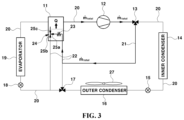
- FIG. 3 is a diagram showing a refrigerant recirculation state that is performed in the early state of a heating mode in the thermal management system according to an embodiment of the present disclosure
- FIG. 4 is a diagram showing a refrigerant recirculation state for refrigerant recirculation and interior heat discharge in a heating mode in the thermal management system according to an embodiment of the present disclosure
- FIG. 5 is a diagram showing a P-H curve in the heating mode of FIG. 4 ;
- FIG. 6 is a diagram showing a refrigerant state in a heating mode in which an interior air heat absorption (interior heat absorption) process in the thermal management system according to an embodiment of the present disclosure
- FIG. 7 is a diagram showing a P-H curve in the heating mode of FIG. 6 ;
- FIG. 8 is a diagram showing a refrigerant state in a cooling mode in the configuration of a thermal management system according to an embodiment of the present disclosure.
- FIG. 9 is a diagram showing a P-H curve in the cooling mode of FIG. 8 .
- first and/or second, etc. may be used herein to describe various elements, but these elements should not be limited by these terms. These terms are only used to distinguish one element from another element. For instance, a first element discussed below could be termed a second element without departing from the teachings of the present disclosure. Similarly, the second element could also be termed the first element.
- FIG. 1 is a diagram showing the configuration of a thermal management system according to an embodiment of the present disclosure, which shows a thermal management circuit for cooling and heating of a vehicle.
- FIG. 2 is a block diagram showing a control element and operation elements in the thermal management system according to an embodiment of the present disclosure, which shows a controller 1 , valves, and a compressor 12 .
- a thermal management system includes an accumulator 11 , a compressor 12 , a first valve 13 , an inner condenser 14 , a second expansion valve 15 , an outer condenser (an air cooled condenser) 16 , a second valve 17 , a first expansion valve 18 , and an evaporator 19 that are disposed along a path through which a refrigerant circulates.
- the components of the thermal management system are connected through a refrigerant line 20 so that a refrigerant can circulate, and the first valve 13 and the second valve 17 , and the first expansion valve 18 and the second expansion valve 15 may be electronic valves having internal channels of which the opening-closing state and the opening amount are controlled by the controller 1 .
- the first valve 13 and the second valve 17 of the valves may be 3-way valves.
- the refrigerant line 20 of the has a second diverging pipe 22 diverging from the refrigerant line at the outlet of the outer condenser 16 , passing through the accumulator 11 , and then connected back to the refrigerant line at the outlet of the outer condenser 16 .
- the second diverging pipe 22 diverges from an upstream position of the refrigerant line at the outlet of the outer condenser 16 in the refrigerant flow direction and is then connected to the inside of the accumulator 11 , and the second valve 17 that is a 3-way valve is installed at the diverging point at the upstream position from which the second diverging pipe 22 diverges in the refrigerant line at the outlet of the outer condenser 16 .
- the second diverging pipe 22 that has passed through the accumulator 11 joins the refrigerant line at a downstream position in the refrigerant flow direction of the refrigerant line at the outlet of the outer condenser 16 , that is, at a downstream position further than the position, at which the second valve 17 is installed, of the refrigerant line at the outlet of the outer condenser 16 .
- the second diverging pipe 22 is installed to pass through the lower portion of the internal space of the accumulator 11 , and a heat exchange unit 23 is installed in the second diverging pipe 22 in the accumulator 11 . That is, the heat exchange unit 23 is installed in the second diverging pipe 22 that passes through the lower portion of the internal space of the accumulator 11 , and the internal channel of the second diverging pipe 22 and the internal channel of the heat exchange unit 23 communicate with each other.
- the heat exchange unit 23 is installed at the line section of the second diverging pipe 22 that is positioned in the accumulator 11 , and a discharge valve 24 that is a 3-way valve is installed at the line section of the second diverging pipe 22 at the outlet of the heat exchange unit 23 to be positioned in the accumulator 11 .
- the discharge valve 24 may also be an electronic valve having an internal channel of which the opening-closing state and the opening amount are controlled by the controller 1 .
- the line section of the second diverging pipe 22 at the outlet of the heat exchange unit 23 is connected to a first port 25 a of the discharge valve 24 installed in the accumulator 11 , so the refrigerant flowing through the second diverging pipe 22 sequentially passes through the heat exchange unit 23 and the discharge valve 24 .
- the line section of the second diverging pipe 22 that extends out of the accumulator 11 and is connected to the refrigerant line at the outlet of the outer condenser 16 is connected to a second port 25 b of the discharge valve 24 in the accumulator 11 .
- the line section of the second diverging pipe 22 that is connected to the refrigerant line 20 between the second valve 17 and the first expansion valve 18 from the inside of the accumulator 11 is connected to the second port 25 b of the discharge valve 24 .
- the discharge valve 24 has a discharge port 25 c for discharging a refrigerant into the accumulator 11 . Accordingly, a refrigerant compressed by the compressor 12 , as will be described below, is recirculated through the first valve 13 , the first diverging pipe 21 , and the second diverging pipe 22 and then discharged into the accumulator 11 through the discharge port 25 c of the discharge valve 24 .
- the first expansion valve 18 is installed in the refrigerant line 20 at a downstream position further than the joining position of the second diverging pipe 22 , the evaporator 19 is installed at a downstream position further than the first expansion valve 18 , and the accumulator 11 is installed at a downstream position further than the evaporator 19 .
- the refrigerant line at the outlet of the first expansion valve is connected to an inlet of the evaporator 19 and the refrigerant line at the outlet of the evaporator 19 is connected to the inlet of the accumulator 11 .
- the refrigerant line at the outlet of the accumulator 11 is connected to the inlet of the compressor 12 and the refrigerant line at the outlet of the compressor 12 is connected to the inlet of the inner condenser 14 . Accordingly, when the compressor 12 is driven, the refrigerant stored in the accumulator 11 can be suctioned and then compressed in the compressor and then discharged to the refrigerant line at the inlet of the inner condenser 14 .
- the second expansion valve 15 is installed in the refrigerant line at the outlet of the inner condenser 14 , the refrigerant line at the outlet of the second expansion valve 15 is connected to the inlet of the outer condenser 16 , and the refrigerant line 20 at the outlet of the outer condenser 16 is connected to the second valve 17 .
- the first diverging pipe 21 diverges from the refrigerant line at the outlet of the compressor 12 and is connected to the line section of the second diverging pipe 22 at the inlet of the accumulator 11 , that is, the line section of the second diverging pipe 22 between the second valve 17 and the accumulator 11 .
- the first valve 13 that is a 3-way valve is installed at the diverging position, at which the first diverging pipe 21 diverges, in the refrigerant line at the outlet of the compressor 12 .
- the first diverging pipe 21 and the second diverging pipe 22 are refrigerant recirculation lines connected to the accumulator 11 from the refrigerant line 20 between the compressor 12 and the inner condenser 14 to recirculate the high-temperature and high-pressure refrigerant compressed by the compressor 12 to the accumulator 11 .
- the first diverging pipe 21 , the second diverging pipe 22 , the first valve 13 , the second valve 17 , and the discharge valve 24 are refrigerant lines and valves constituting a refrigerant recirculation circuit for recirculating the high-temperature and high-pressure refrigerant compressed by the compressor 12 to the accumulator 11 , and are used to recirculate the high-temperature and high-pressure refrigerant compressed by the compressor to the accumulator 11 through the first valve 13 from the refrigerant lines at the inlet of the inner condenser 14 and the outlet of the compressor 12 while the compressor 12 is driven.
- the accumulator 11 , the compressor 12 , the outer condenser 16 , the first expansion valve 18 , and the evaporator 19 are components of well-known air conditioning systems that recirculate a refrigerant and use a refrigeration cycle.
- the compressor 12 may be an electric compressor that is operated by power from a battery.
- the internal heat exchanger (IHX) in the configuration may be the inner condenser 14 , the evaporator 19 , the accumulator 11 that shows a double-pipe effect in heating while functioning as a vapor-liquid separator, or the like.
- the accumulator 11 in the configuration is provided such that a refrigerant is separated into vapor and liquid therein, the refrigerant line at the outlet of the evaporator 19 is connected to the refrigerant inlet of the accumulator 11 , and the refrigerant line at the inlet of the compressor 12 is connected to the refrigerant outlet of the accumulator 11 .
- the accumulator 11 has a heat exchanger type of device configuration having the heat exchange unit 23 through which a refrigerant passes.
- the accumulator 11 is installed in the refrigerant line 20 between the evaporator 19 and the compressor 12 such that only a gas-state refrigerant is supplied to the compressor 12 , thereby improving efficiency and durability of the compressor.
- the compressor 12 in the configuration is a component for compressing a refrigerant, and the inner condenser 14 and the outer condenser 16 , which are provided such that heat exchange occurs between a refrigerant and air, condense the refrigerant compressed by the compressor 12 into liquid.
- the inner condenser 14 of the two condensers is installed in a passage for supplying heating air into a vehicle, and the outer condenser 16 may be installed at the front of a car body through which air, which flows inside through an opening at the front of a vehicle, can pass.
- An electric heater (e.g., a PTC heater) not shown may be further installed in the passage in which the inner condenser 14 is installed.
- the electric heater is operated by power from a battery and the operation of the electric heater is controlled by the controller 1 .
- the electric heater When the electric heater operates, the electric heater heats heating air that is blown by a blower 26 , and heating air heated while passing through the electric heater is supplied into a vehicle, whereby heating can be performed.
- the second expansion valve 15 is installed in the refrigerant line at the inlet of the outer condenser 16 and the first expansion valve 18 is installed in the refrigerant line at the inlet of the evaporator 19 .
- the first expansion valve 18 and the second expansion valve 15 both serve to expand a refrigerant liquefied through condensation, and each may have an expansion section and a bypass passage in a valve body thereof.
- the first expansion valve 18 and the second expansion valve 15 are both may be electronic expansion valves having an internal channel of which the opening-closing state and the opening amount are controlled by the controller 1 .
- the bypass passage is fully opened and the internal channel of the expansion section is closed, whereby a refrigerant flows only through the bypass passage without flowing through the refrigerant channel of the expansion section. Since a refrigerant passes through the bypass passage of the first expansion valve 18 and the second expansion valve 15 and bypasses the expansion section, the refrigerant does not expand.
- the evaporator 19 cools air that is blown into a vehicle using latent heat of evaporation of the refrigerant expanding through the first expansion valve 18 while evaporating the refrigerant.
- the evaporator 19 may be installed in an air passage that is connected to the interior of a vehicle to supply heating air into the vehicle, that is, may be installed in a heating air passage provided separately from the heating air passage in which the inner condenser 14 is installed.
- cooling air suctioned by the blower 26 passes through the evaporator 19 , is cooled by a low-temperature refrigerant in the evaporator while passing through the evaporator 19 , and is then discharged into a vehicle, whereby interior heating is performed.
- thermal management system The configuration of a thermal management system according to an embodiment of the present disclosure was described above, and operation modes of the thermal management system are described in detail hereafter.
- thermal management system of the present disclosure it is possible to achieve a refrigerant recirculation effect using the accumulator 11 that functions as a vapor-liquid separator and it is possible to provide an operation mode that uses the refrigerant recirculation effect.
- the thermal management system of the present disclosure can perform both heating and cooling using only a refrigerant and can implement a Tesla Lossy mode, in which heat for heating is supplied using compressor work, using only a refrigerant even without cooling water.
- the accumulator 11 and the heat exchange unit may be used as an internal heat exchanger IHX and the heat exchange unit 23 that performs heat exchange with a refrigerant is installed in the accumulator 110 , so a double-pipe effect can be achieved by the accumulator 11 and the heat exchange unit 23 .
- a Tesla Lossy mode in heating and a double-pipe effect in cooling can be achieved, energy efficiency of the thermal management system can be improved, and both the cooling performance and the heating performance of the thermal management system can be improved.
- FIGS. 3 and 4 are diagrams showing a heating mode of the thermal management system according to an embodiment of the present disclosure.
- FIG. 3 shows a refrigerant recirculation state that is performed in the early stage of the heating mode and
- FIG. 4 shows a refrigerant recirculation state for refrigerant recirculation and interior heat discharge in the heating mode.
- FIG. 5 is a diagram showing a P-H curve in the heating mode of FIG. 4 .
- the controller 1 drives and controls the compressor such that compressor work, that is, additional load is generated in the compressor 12 , and a refrigerant compressed at a high temperature and a high pressure is discharged through the outlet of the compressor 12 that is in operation.
- the controller 1 controls the opening state of the discharge valve 24 such that the refrigerant recirculated to the accumulator 11 from the compressor 12 can be discharged into the accumulator 11 through the discharge port 25 c of the discharge valve 24 .
- the position of a valve body in a valve housing is controlled by the controller 1 to close only the internal channel connected to the second port 25 b in the discharge valve 24 .
- the controller 1 controls also the opening states of the first valve 13 and the second valve 17 . That is, in the first valve 13 , a valve body in a valve housing is controlled to close the internal channel that is connected to the outlet port connected with the refrigerant line at the inlet of the inner condenser 14 and to open the internal channels that are respectively connected to the inlet port connected with the refrigerant line at the outlet of the compressor 12 and to the diverging port connected with the first diverging pipe 21
- a valve body in a valve housing is controlled to close all of the internal channels that are respectively connected to the outlet port connected with the refrigerant line at the inlet of the first expansion valve 18 and to the diverging port connected with the second diverging pipe 22 .
- the first diverging pipe 21 and the second diverging pipe 22 are refrigerant lines constituting a refrigerant recirculation circuit for recirculating the high-temperature and high-pressure refrigerant discharged from the compressor 12 to the accumulator 11 .
- the refrigerant recirculation circuit is used to recirculate the high-temperature and high-pressure refrigerant compressed by the compressor 12 to the accumulator 11 from the refrigerant line at the outlet of the compressor 12 through the first valve 13 and the discharge valve 24 while the compressor is driven in the early stage of the heating mode.
- the temperature and pressure of the refrigerant discharged from the compressor are increased to predetermined levels by compressor work (load) and a refrigerant recirculation effect during the early stage of the heating mode, the process is changed into the heating mode shown in FIG. 4 to perform both refrigerant recirculation and interior heating of a vehicle.
- the controller 1 controls the opening state and the opening amount of the first valve 13 such that a portion of the refrigerant discharged from the compressor 12 flows to the inner condenser 14 from the first valve 13 through the refrigerant line 20 and the other refrigerant is recirculated to the accumulator 11 through the refrigerant recirculation circuit in the same way as the early stage of the heating mode shown in FIG. 3 .
- the other refrigerant distributed to the first diverging pipe 21 of the refrigerant recirculation circuit through the first valve 13 flows to the accumulator 11 through the first diverging pipe 21 , the second diverging pipe 22 , and the discharge valve 24 in the same way as the early stage of the heating mode described above.
- a portion of the refrigerant compressed by the compressor 12 may be recirculated through a heating circuit including the inner condenser 14 to be used for heating, and the high-temperature and high-pressure refrigerant compressed by the compressor 12 heats the air flowing around the inner condenser while passing through the inner condenser 14 .
- the heating air blown by the blower 26 and the high-temperature and high-pressure refrigerant passing through the inner condenser 14 exchange heat with each other in the inner condenser 14 , and the heating air heated by the refrigerant at the inner condenser 14 is discharged into a vehicle, whereby heating is performed (“interior heat discharge”).
- the refrigerant that has passed through the inner condenser 14 passes through the second expansion valve 15 .
- the second expansion valve is controlled by the controller 1 such that the refrigerant channel of the expansion section is opened, and accordingly, the refrigerant that has passed through the inner condenser 14 expands through the expansion section of the second expansion valve 15 and the expanding refrigerant flows at a low temperature and a low pressure to the outer condenser 16 .
- External air that is, air flowing inside through the opening at the front of a vehicle is supposed to pass through the outer condenser 16 , and external air suctioned by a cooling fan 27 can pass through the outer condenser 16 .
- the first expansion valve 18 is controlled to be fully opened by the controller 1 , so the bypass passage is opened. Accordingly, the refrigerant flows through the bypass passage without passing through the expansion section of the first expansion valve 18 , so the refrigerant intactly flows to the evaporator 19 without expanding. As a result, the refrigerant that has passed through the evaporator 19 flows to the compressor 12 after mixed with the refrigerant in the accumulator 11 , and then undergoes again the refrigerant recirculation process described above.
- a portion of the high-temperature and high-pressure refrigerant discharged from the compressor 12 flows to the heating circuit such that a heating mode is performed, and the other small amount of refrigerant is recirculated to the accumulator 11 . Accordingly, it is possible to increase the heat amount of the thermal management system through refrigerant recirculation instead of using an electric heater.
- refrigerant recirculation can be stopped, and a normal heating mode in which all the high-temperature and high-pressure refrigerant compressed by the compressor 12 is recirculated through a heating circuit with refrigerant recirculation stopped can be performed.
- the internal channel connected to the diverging port connected with the first diverging pipe 21 is closed, and the internal channels connected to the inlet port, which is connected with the refrigerant line at the outlet of the compressor 12 , and the outlet port connected with the refrigerant line at the inlet of the inner condenser 14 are opened.
- FIG. 6 is a diagram showing a refrigerant state in a heating mode in which the interior air heat absorption (“interior heat absorption”) process is further performed in addition to refrigerant recirculation, interior heat discharge, and external air heat absorption
- FIG. 7 is a diagram showing a P-H curve in a heating mode.
- the heating mode shown in FIG. 4 is a mode in which an external air heat absorption process is performed in addition to refrigerant recirculation and interior heat discharge for heating the interior of a vehicle, and in the heating mode shown in FIG. 4 , heat can be supplied to the accumulator 11 that is a vapor-liquid separator by the refrigerant recirculation and the external air heat absorption process.
- the heating mode shown in FIG. 6 is a mode in which an interior air heat absorption (“interior heat absorption”) process is further performed in addition to refrigerant recirculation and interior heat discharge for heating the interior of a vehicle, and the an external air heat absorption process, and in the heating mode shown in FIG. 6 , heat can be supplied to the accumulator 11 that is a vapor-liquid separator by the refrigerant recirculation, the external air heat absorption process, and the added interior heat absorption process.
- an interior air heat absorption (“interior heat absorption”) process is further performed in addition to refrigerant recirculation and interior heat discharge for heating the interior of a vehicle, and the an external air heat absorption process, and in the heating mode shown in FIG. 6 , heat can be supplied to the accumulator 11 that is a vapor-liquid separator by the refrigerant recirculation, the external air heat absorption process, and the added interior heat absorption process.
- the process of refrigerant recirculation in the heating mode shown in FIG. 6 is not different from that described with reference to FIGS. 3 and 4 .
- the process in which heating is performed through interior heat discharge from the inner condenser 14 and the exterior air heat absorption process by the outer condenser 16 in the heating mode shown in FIG. 6 are also not different from that described with reference to FIGS. 3 and 4 .
- a refrigerant expands through the second expansion valve 15 after passing through the inner condenser 14 , and the refrigerant that has expanded through the second expansion valve 15 passes through the outer condenser 16 .
- the second expansion valve 15 is controlled by the controller 1 such that the refrigerant channel of the expansion section thereof is opened, so the refrigerant that has passed through the inner condenser 14 can expand through the refrigerant channel of the expansion section in the second expansion valve 15 .
- an external air heat absorption process of a refrigerant is performed in the outer condenser 16 , and while a refrigerant passes through the outer condenser 16 , the refrigerant receives heat from the external air flowing around the outer condenser 16 and then flows back to the first expansion valve 18 through the refrigerant line 20 .
- the refrigerant since the refrigerant has sufficiently reached a low temperature and a low pressure through the second expansion valve 15 , the refrigerant passes through the bypass passage of the first expansion valve 18 without expanding after undergoing the external heat absorption process in the outer condenser 16 .
- the first expansion valve 18 is controlled to be fully opened by the controller 1 , and in this case, the bypass passage of the first expansion valve 18 is opened. Accordingly, a refrigerant does not pass through the expansion section of the first expansion valve 18 and intactly flow to the evaporator 19 without expanding through the bypass passage.
- the refrigerant that has passed through the evaporator 19 , as described above, thereafter, is recovered into the accumulator 11 through the refrigerant line 20 , and the recovered refrigerant is mixed with the refrigerant in the accumulator 11 . Thereafter, the refrigerant in the accumulator 11 flows to the compressor 12 and then undergoes again the refrigerant recirculation process described above.
- refrigerant recirculation interior heat discharge (interior air heat discharge), external air heat absorption, and interior air heat absorption (“interior heat absorption”) can be simultaneously performed, and the refrigerant recirculation of these processes may be stopped, if necessary.
- a portion of a heat amount that is provided by compressor work can be supplied into the accumulator 11 , which is a vapor-liquid separator, by refrigerant recirculation, and accordingly, a refrigerant that has absorbed heat supplied into the accumulator 11 can be supplied from the accumulator 11 to the compressor 12 .
- the refrigerant receiving heat at the accumulator 11 in the refrigerant recirculation process during the heating mode recirculates through a refrigerant circuit such as a heating circuit.
- refrigerant recirculation, and external air heat absorption and internal air heat absorption processes can be simultaneously performed by controlling compressor work (load) and valves, and heat can be continuously supplied to the accumulator 11 that is a vapor-liquid separator by the refrigerant recirculation, and external air heat absorption and internal air heat absorption processes.
- a refrigerant is sent under pressure by driving the compressor 12 , that is, a refrigerant is compressed at a high temperature and a high pressure and then sent out, it is possible to increase a refrigerant recirculation amount, and accordingly, it is possible to improve heat pump performance.
- FIG. 8 is a diagram showing refrigerant circulation and state in a cooling mode in the configuration of a thermal management system according to an embodiment of the present disclosure
- FIG. 9 is a diagram showing a P-H curve in the cooling mode of FIG. 8 .
- a refrigerant circulates in order of the accumulator 11 , the compressor 12 , the outer condenser 16 , the first expansion valve 18 , and the evaporator 19 .
- the operation and functions of the compressor 12 , the outer condenser 16 , the first expansion valve 18 , and the evaporator 19 that are operated during the cooling mode are not different from those of the main components that perform the process of a refrigeration cycle in well-known air conditioning systems, that is, the operation and functions of a compressor, a condenser, an expansion valve, and an evaporator that are well known in the art.
- the internal channel connected to the diverging port connected with the first diverging pipe 21 is controlled to be closed, and the internal channels connected to the outlet port, which is connected with the refrigerant line at the outlet of the evaporator 19 , and the inlet port connected with the refrigerant line at the inlet of the inner condenser 14 are controlled to be opened.
- the second expansion valve 15 is controlled to be fully opened such that the expansion section is closed and the bypass passage is opened, whereby the high-temperature and high-pressure refrigerant passes through the second expansion valve 15 without expanding and then flows to the outer condenser 16 and keeps flowing through the outer condenser 16 .
- the refrigerant cooled and condensed by air in the outer condenser 16 flows from the second valve 17 to the second diverging pipe 22 , moves to the accumulator 11 through the second diverging pipe 22 , and then passes through the heat exchange unit 23 in the accumulator 11 .
- the opening-closing state of the second valve 17 is controlled by the controller 1 such that the refrigerant that has passed through the outer condenser 16 can flow to the accumulator 11 through the second diverging pipe 22 from the second valve 17 . That is, the opening-closing state of the second valve 17 is controlled such that the refrigerant channel connected to the outlet port connected with the refrigerant line at the inlet of the first expansion valve 18 is closed and the internal channels connected to the inlet port connected with the refrigerant line at the outlet of the outer condenser 16 and to the diverging port connected with the second diverging pipe 22 are opened.
- the refrigerant that has passed through the heat exchange unit 23 in the accumulator 11 is discharged from the accumulator 11 , flows through the second diverging pipe 22 , and then moves to the refrigerant line at the inlet of the first expansion valve 18 from the second diverging pipe 22 .
- the expansion section is controlled to be closed and the bypass passage is controlled to be fully opened in the second expansion valve but the bypass passage is controlled to be opened and the expansion section is controlled to be opened in the first expansion valve 18 so that a refrigerant can expand well. Accordingly, a refrigerant expands into a low-temperature and low-pressure state in the first expansion valve 18 and then flows to the evaporator 19 .
- the air cooled by the refrigerant at the evaporator 19 is discharged in a vehicle, whereby the interior of the vehicle is cooled.
- the refrigerant that has passed through the evaporator 19 moves to the accumulator 11 and is then circulated again through the same refrigerant circuit by the compressor 12 during the cooling mode.
- the opening state of the internal channels of the discharge valve 25 is controlled by the controller 1 such that the first port 25 a and the second port 25 b communicate with each other and the discharge port 25 c is closed. Accordingly, all the refrigerant that has passed through the heat exchange unit 23 flows to the second diverging pipe 22 outside the accumulator 11 without flowing into the accumulator 11 .
- the accumulator 11 which is a vapor-liquid separator, and the heat exchange unit 23 can be used as internal heat exchangers (IHX), so a double-pipe effect can also be secured.
Landscapes
- Engineering & Computer Science (AREA)
- Physics & Mathematics (AREA)
- Thermal Sciences (AREA)
- Mechanical Engineering (AREA)
- General Engineering & Computer Science (AREA)
- Analytical Chemistry (AREA)
- Chemical & Material Sciences (AREA)
- Power Engineering (AREA)
- Software Systems (AREA)
- Theoretical Computer Science (AREA)
- Mathematical Physics (AREA)
- Fuzzy Systems (AREA)
- Air-Conditioning For Vehicles (AREA)
Abstract
Description
Claims (14)
Applications Claiming Priority (2)
| Application Number | Priority Date | Filing Date | Title |
|---|---|---|---|
| KR1020220094307A KR20240016469A (en) | 2022-07-29 | 2022-07-29 | Thermal management system for vehicle |
| KR10-2022-0094307 | 2022-07-29 |
Publications (2)
| Publication Number | Publication Date |
|---|---|
| US20240034127A1 US20240034127A1 (en) | 2024-02-01 |
| US12220971B2 true US12220971B2 (en) | 2025-02-11 |
Family
ID=89508346
Family Applications (1)
| Application Number | Title | Priority Date | Filing Date |
|---|---|---|---|
| US18/068,015 Active 2043-06-29 US12220971B2 (en) | 2022-07-29 | 2022-12-19 | Thermal management system for vehicle |
Country Status (4)
| Country | Link |
|---|---|
| US (1) | US12220971B2 (en) |
| KR (1) | KR20240016469A (en) |
| CN (1) | CN117465183A (en) |
| DE (1) | DE102022134671A1 (en) |
Citations (3)
| Publication number | Priority date | Publication date | Assignee | Title |
|---|---|---|---|---|
| US20140090407A1 (en) * | 2011-03-24 | 2014-04-03 | Airbus Operations Gmbh | Multifunctional refrigerant container and method of operating such a refrigerant container |
| US20160052365A1 (en) * | 2013-06-14 | 2016-02-25 | Mitsubishi Heavy Industries Automotive Thermal Systems Co., Ltd. | Heat-pump-type vehicular air-conditioning system |
| US20180222287A1 (en) * | 2015-08-04 | 2018-08-09 | Denso Corporation | Heat pump system |
-
2022
- 2022-07-29 KR KR1020220094307A patent/KR20240016469A/en active Pending
- 2022-12-19 US US18/068,015 patent/US12220971B2/en active Active
- 2022-12-23 DE DE102022134671.4A patent/DE102022134671A1/en active Pending
- 2022-12-27 CN CN202211691488.8A patent/CN117465183A/en active Pending
Patent Citations (3)
| Publication number | Priority date | Publication date | Assignee | Title |
|---|---|---|---|---|
| US20140090407A1 (en) * | 2011-03-24 | 2014-04-03 | Airbus Operations Gmbh | Multifunctional refrigerant container and method of operating such a refrigerant container |
| US20160052365A1 (en) * | 2013-06-14 | 2016-02-25 | Mitsubishi Heavy Industries Automotive Thermal Systems Co., Ltd. | Heat-pump-type vehicular air-conditioning system |
| US20180222287A1 (en) * | 2015-08-04 | 2018-08-09 | Denso Corporation | Heat pump system |
Also Published As
| Publication number | Publication date |
|---|---|
| DE102022134671A1 (en) | 2024-02-01 |
| KR20240016469A (en) | 2024-02-06 |
| CN117465183A (en) | 2024-01-30 |
| US20240034127A1 (en) | 2024-02-01 |
Similar Documents
| Publication | Publication Date | Title |
|---|---|---|
| CN116194313B (en) | Steam injection module and heat pump system using the same | |
| KR101656583B1 (en) | Air conditioning system for a motor vehicle | |
| US10882377B2 (en) | Cooling and heating system for vehicle | |
| CN102781693B (en) | vehicle climate control system and temperature control method | |
| KR101192346B1 (en) | Heat pump type speed heating apparatus | |
| KR102111322B1 (en) | Heat pump system for vehicle | |
| KR101015640B1 (en) | Vehicle air conditioning system | |
| US20100000713A1 (en) | Vehicle air conditioning system | |
| KR20180007021A (en) | Heat pump system for vehicle | |
| CN116056922B (en) | Steam injection module and heat pump system using the steam injection module | |
| CN106061777A (en) | Heat pump system for vehicle | |
| KR20160110063A (en) | Air-conditioning system of a motor vehicle and method for operating the air-conditioning system | |
| CN102679477A (en) | Heat pump system for vehicle | |
| KR20210126361A (en) | Vapor injection heat pump system | |
| CN221090418U (en) | Indirect heat pump thermal management system and vehicle | |
| CN113547956A (en) | Vehicle thermal management system | |
| CN114475161A (en) | Heat management system of automobile and automobile | |
| JP2020192965A (en) | Heat exchange system | |
| CN109982877B (en) | Vehicle heat pump system | |
| KR20200060633A (en) | Cooling and heating system for vehicle | |
| KR102587577B1 (en) | Air conditioning system | |
| KR20190098068A (en) | Heat pump system for vehicle | |
| CN116605005A (en) | Automotive thermal management system and automobile | |
| US20250222743A1 (en) | Thermal management system for a vehicle | |
| US12220971B2 (en) | Thermal management system for vehicle |
Legal Events
| Date | Code | Title | Description |
|---|---|---|---|
| AS | Assignment |
Owner name: KIA CORPORATION, KOREA, REPUBLIC OF Free format text: ASSIGNMENT OF ASSIGNORS INTEREST;ASSIGNOR:KIM, JONG WON;REEL/FRAME:062143/0614 Effective date: 20221206 Owner name: HYUNDAI MOTOR COMPANY, KOREA, REPUBLIC OF Free format text: ASSIGNMENT OF ASSIGNORS INTEREST;ASSIGNOR:KIM, JONG WON;REEL/FRAME:062143/0614 Effective date: 20221206 |
|
| FEPP | Fee payment procedure |
Free format text: ENTITY STATUS SET TO UNDISCOUNTED (ORIGINAL EVENT CODE: BIG.); ENTITY STATUS OF PATENT OWNER: LARGE ENTITY |
|
| STPP | Information on status: patent application and granting procedure in general |
Free format text: DOCKETED NEW CASE - READY FOR EXAMINATION |
|
| STPP | Information on status: patent application and granting procedure in general |
Free format text: NON FINAL ACTION MAILED |
|
| STPP | Information on status: patent application and granting procedure in general |
Free format text: RESPONSE TO NON-FINAL OFFICE ACTION ENTERED AND FORWARDED TO EXAMINER |
|
| STPP | Information on status: patent application and granting procedure in general |
Free format text: NOTICE OF ALLOWANCE MAILED -- APPLICATION RECEIVED IN OFFICE OF PUBLICATIONS |
|
| STPP | Information on status: patent application and granting procedure in general |
Free format text: PUBLICATIONS -- ISSUE FEE PAYMENT VERIFIED |
|
| STCF | Information on status: patent grant |
Free format text: PATENTED CASE |