US12220943B2 - Driving mechanism of bicycle free-coaster hub - Google Patents
Driving mechanism of bicycle free-coaster hub Download PDFInfo
- Publication number
- US12220943B2 US12220943B2 US17/882,804 US202217882804A US12220943B2 US 12220943 B2 US12220943 B2 US 12220943B2 US 202217882804 A US202217882804 A US 202217882804A US 12220943 B2 US12220943 B2 US 12220943B2
- Authority
- US
- United States
- Prior art keywords
- hub
- driving mechanism
- gear
- sun gear
- clutch
- Prior art date
- Legal status (The legal status is an assumption and is not a legal conclusion. Google has not performed a legal analysis and makes no representation as to the accuracy of the status listed.)
- Active, expires
Links
- 210000000078 claw Anatomy 0.000 claims description 7
- 230000001133 acceleration Effects 0.000 description 2
- 238000005096 rolling process Methods 0.000 description 2
- 238000009987 spinning Methods 0.000 description 2
- 230000003292 diminished effect Effects 0.000 description 1
- 239000007769 metal material Substances 0.000 description 1
- 238000012986 modification Methods 0.000 description 1
- 230000004048 modification Effects 0.000 description 1
- 230000001681 protective effect Effects 0.000 description 1
- 239000002699 waste material Substances 0.000 description 1
Images


Classifications
-
- B—PERFORMING OPERATIONS; TRANSPORTING
- B60—VEHICLES IN GENERAL
- B60B—VEHICLE WHEELS; CASTORS; AXLES FOR WHEELS OR CASTORS; INCREASING WHEEL ADHESION
- B60B27/00—Hubs
- B60B27/0015—Hubs for driven wheels
- B60B27/0021—Hubs for driven wheels characterised by torque transmission means from drive axle
- B60B27/0026—Hubs for driven wheels characterised by torque transmission means from drive axle of the radial type, e.g. splined key
-
- B—PERFORMING OPERATIONS; TRANSPORTING
- B60—VEHICLES IN GENERAL
- B60B—VEHICLE WHEELS; CASTORS; AXLES FOR WHEELS OR CASTORS; INCREASING WHEEL ADHESION
- B60B27/00—Hubs
- B60B27/02—Hubs adapted to be rotatably arranged on axle
- B60B27/023—Hubs adapted to be rotatably arranged on axle specially adapted for bicycles
-
- B—PERFORMING OPERATIONS; TRANSPORTING
- B60—VEHICLES IN GENERAL
- B60B—VEHICLE WHEELS; CASTORS; AXLES FOR WHEELS OR CASTORS; INCREASING WHEEL ADHESION
- B60B27/00—Hubs
- B60B27/02—Hubs adapted to be rotatably arranged on axle
- B60B27/04—Hubs adapted to be rotatably arranged on axle housing driving means, e.g. sprockets
- B60B27/047—Hubs adapted to be rotatably arranged on axle housing driving means, e.g. sprockets comprising a freewheel mechanisms
-
- B—PERFORMING OPERATIONS; TRANSPORTING
- B60—VEHICLES IN GENERAL
- B60B—VEHICLE WHEELS; CASTORS; AXLES FOR WHEELS OR CASTORS; INCREASING WHEEL ADHESION
- B60B35/00—Axle units; Parts thereof ; Arrangements for lubrication of axles
- B60B35/12—Torque-transmitting axles
- B60B35/121—Power-transmission from drive shaft to hub
- B60B35/122—Power-transmission from drive shaft to hub using gearings
- B60B35/125—Power-transmission from drive shaft to hub using gearings of the planetary type
-
- B—PERFORMING OPERATIONS; TRANSPORTING
- B62—LAND VEHICLES FOR TRAVELLING OTHERWISE THAN ON RAILS
- B62M—RIDER PROPULSION OF WHEELED VEHICLES OR SLEDGES; POWERED PROPULSION OF SLEDGES OR SINGLE-TRACK CYCLES; TRANSMISSIONS SPECIALLY ADAPTED FOR SUCH VEHICLES
- B62M11/00—Transmissions characterised by the use of interengaging toothed wheels or frictionally-engaging wheels
- B62M11/04—Transmissions characterised by the use of interengaging toothed wheels or frictionally-engaging wheels of changeable ratio
- B62M11/14—Transmissions characterised by the use of interengaging toothed wheels or frictionally-engaging wheels of changeable ratio with planetary gears
- B62M11/16—Transmissions characterised by the use of interengaging toothed wheels or frictionally-engaging wheels of changeable ratio with planetary gears built in, or adjacent to, the ground-wheel hub
-
- F—MECHANICAL ENGINEERING; LIGHTING; HEATING; WEAPONS; BLASTING
- F16—ENGINEERING ELEMENTS AND UNITS; GENERAL MEASURES FOR PRODUCING AND MAINTAINING EFFECTIVE FUNCTIONING OF MACHINES OR INSTALLATIONS; THERMAL INSULATION IN GENERAL
- F16D—COUPLINGS FOR TRANSMITTING ROTATION; CLUTCHES; BRAKES
- F16D41/00—Freewheels or freewheel clutches
- F16D41/24—Freewheels or freewheel clutches specially adapted for cycles
- F16D41/28—Freewheels or freewheel clutches specially adapted for cycles with intermediate wedging coupling members
-
- F—MECHANICAL ENGINEERING; LIGHTING; HEATING; WEAPONS; BLASTING
- F16—ENGINEERING ELEMENTS AND UNITS; GENERAL MEASURES FOR PRODUCING AND MAINTAINING EFFECTIVE FUNCTIONING OF MACHINES OR INSTALLATIONS; THERMAL INSULATION IN GENERAL
- F16D—COUPLINGS FOR TRANSMITTING ROTATION; CLUTCHES; BRAKES
- F16D41/00—Freewheels or freewheel clutches
- F16D41/24—Freewheels or freewheel clutches specially adapted for cycles
- F16D41/30—Freewheels or freewheel clutches specially adapted for cycles with hinged pawl co-operating with teeth, cogs, or the like
-
- F—MECHANICAL ENGINEERING; LIGHTING; HEATING; WEAPONS; BLASTING
- F16—ENGINEERING ELEMENTS AND UNITS; GENERAL MEASURES FOR PRODUCING AND MAINTAINING EFFECTIVE FUNCTIONING OF MACHINES OR INSTALLATIONS; THERMAL INSULATION IN GENERAL
- F16D—COUPLINGS FOR TRANSMITTING ROTATION; CLUTCHES; BRAKES
- F16D41/00—Freewheels or freewheel clutches
- F16D41/24—Freewheels or freewheel clutches specially adapted for cycles
- F16D41/34—Freewheels or freewheel clutches specially adapted for cycles with expandable or contractable clamping ring or band
-
- F—MECHANICAL ENGINEERING; LIGHTING; HEATING; WEAPONS; BLASTING
- F16—ENGINEERING ELEMENTS AND UNITS; GENERAL MEASURES FOR PRODUCING AND MAINTAINING EFFECTIVE FUNCTIONING OF MACHINES OR INSTALLATIONS; THERMAL INSULATION IN GENERAL
- F16H—GEARING
- F16H1/00—Toothed gearings for conveying rotary motion
- F16H1/28—Toothed gearings for conveying rotary motion with gears having orbital motion
-
- B—PERFORMING OPERATIONS; TRANSPORTING
- B60—VEHICLES IN GENERAL
- B60B—VEHICLE WHEELS; CASTORS; AXLES FOR WHEELS OR CASTORS; INCREASING WHEEL ADHESION
- B60B35/00—Axle units; Parts thereof ; Arrangements for lubrication of axles
- B60B35/12—Torque-transmitting axles
-
- B—PERFORMING OPERATIONS; TRANSPORTING
- B60—VEHICLES IN GENERAL
- B60Y—INDEXING SCHEME RELATING TO ASPECTS CROSS-CUTTING VEHICLE TECHNOLOGY
- B60Y2200/00—Type of vehicle
- B60Y2200/10—Road Vehicles
- B60Y2200/13—Bicycles; Tricycles
Definitions
- the disclosure relates to bicycle hubs, and particularly to a driving mechanism of a bicycle free-coaster hub.
- Typical driven bicycle hubs operate through some form of over-running clutch. Often this is a simple ratchet mechanism that allows any forward drive relative to the wheel to engage the hub. A drawback of this arrangement is that any attempt to move the bicycle backwards is indistinguishable from forward drive to the mechanism and so forces the cranks and pedals to rotate backwards. For riders who wish to ride backwards (e.g., for trick riding) this is inconvenient.
- freecoaster hubs are often made with a large degree of backlash or “slack” before engagement occurs.
- slack backlash
- the rider needs to make a large pedaling motion before drive engages. This reduces the chances of accidental engagement of the drive.
- having this large degree of slack is undesirable when pedaling the bicycle forwards. It makes acceleration slower and pedaling engagement more jerky.
- the rider must deliberately reset this slack to ensure that drive is not accidentally engaged. That is, after pedaling, and before turning the bicycle around to coast backwards, the rider should back-pedal slightly to re-open the slack or “gap” between the drive elements and the driven part of the hub.
- this slack or “gap” can be inconsistent. So, if a hub is designed such that the maximum slack/gap is a quarter turn at the pedal, the rider would need to back-pedal at least a quarter turn to fully open the gap. If the rider misjudges this and only back-pedals a tenth of a turn, or if the drive mechanism is shaken by an impact such as landing from a trick/jump, then the angle of pedal movement before engagement may well be less. This member that a rider can never quite be sure how much they will need to pedal before engaging drive. If drive engages sooner or later than expected it can throw off the rider's balance and possibly even cause the rider to come off the bicycle. To counteract this, riders will often pedal very cautiously initially to ensure drive is properly engaged before pedaling hard to gain speed, this can waste precious time or space for acceleration between tricks.
- a hub design has been disclosed that attempts to partially remedy these problems by constantly biasing the drive elements of the hub against the direction of wheel rotation; such that forward movement of the hub biases the elements towards engagement and backward movement of the hub biases the elements out of engagement.
- this approach still has its flaws. It allows for an undesirable outcome in the situation where the wheel of the bicycle is spinning forwards (for example in the air during a jump) immediately before landing rolling backwards. Because the forward spinning wheel is constantly biasing the drive elements into engagement there is a good chance that, on landing, they will engage before the wheel has rotated backwards enough to pull them out of engagement. The result of this is that the drive may be forcibly engaged on landing and again throw the rider from the bicycle by the sudden forceful backward movement of the cranks.
- one of the objectives of the disclosure is to provide a driving mechanism of a bicycle free-coaster hub which can maintain a constant gap or slack between the driving system of the bicycle hub and the driven element when the bicycle wheel is coasting backward or when the bicycle is freewheeling forwards.
- the driving mechanism of a bicycle free-coaster hub is disposed within a cavity defined by a hub axle and a hub shell.
- the driving mechanism comprises a driving assembly, a clutch assembly, an epicyclic gear assembly, a resisting member, a forward drag member and a reverse drag member.
- the driving assembly comprises a sprocket having a plurality of sprocket teeth projecting radially relative to the hub axle and a drive sleeve projecting axially from the sprocket wherein a cylindrical axle hole is defined by the sprocket and the drive sleeve for being passed through both by the hub axle.
- the clutch assembly includes an output clutch unit disposed on the cavity of the hub and an input clutch unit coupled with the drive sleeve to form a clutching or engaging state with the output clutch unit.
- the epicyclic gear assembly includes a sun gear, a ring gear, a planet gear carrier and a plurality of planet gears.
- the sun gear includes a disk coupled with the input clutch unit, a gear portion extending axially from the disk and a first through hole defined by the disk and the gear portion for being passed therethrough by the hub axle.
- the ring gear is mounted on an inner wall of the hub shell.
- the planet gear carrier includes an annular body defined a second through hole for being passed therethrough by the hub axle and a plurality of planet gear arms fixed to the annular body at intervals.
- Each of planetary gears is connected to each of the planetary gear arms and engaged respectively with the ring gear and the gear portion of the sun gear.
- the resisting member is disposed between the sun gear and the hub axle to apply resistance to the rotation of the sun gear.
- the forward drag member is disposed between the ring gear and the sun gear to apply drag to the sun gear when the hub rotates forward.
- the reverse drag member is disposed between the planet gear carrier and the hub axel to apply drag to the planet gear carrier when the hub rotates in reverse.
- the output clutch unit includes a hub shell liner mounted on the inner wall of the hub shell and having an engaged surface facing to the hub axle and the input clutch unit includes a plurality of cams, a first cam receiver, a second cam receiver and a first retaining unit.
- Each of the cams has a first portion, a second portion, an inner surface and a roughened outer surface.
- the first cam receiver includes a plurality of receiving rooms integrally and angularly disposed on the drive sleeve.
- Each of the receiving rooms includes a first ramp and a second ramp arranged symmetrically with the first ramp.
- Each of the ramps has a first top portion with a first radial distance to the axis of the hub axle and a first bottom portion with a second radial distance to the axis of the hub axle wherein the first radial distance is greater than the second radial distance.
- the first portion of each of the cams is received respectively in each of the receiving rooms of the first ramp or the second ramp in a way that each of the cams can slide along the first ramp or the second ramp from the bottom portion to the top portion or the top portion to the bottom portion to enable the roughened outer surface of each of the cams to engage or disengage the engaged surface of the hub shell liner.
- the second cam receiver includes a plurality of pockets disposed on the disk of the sun gear for receiving the second portion of each of the cams so that each of the cams is constrained to the sun gear.
- the first retaining unit includes a retaining device and a coil-spring wherein the retaining device is received in one of the receiving rooms and in contact with the first or second ramps thereof and the coil-spring has one end inserted into the retaining device and a coil body encircled on the outer surface of each of the cams and the retaining piece respectively so that each of the cams can be moved stably along the first or second ramps of each of the receiving rooms.
- the output clutch unit includes a hub shell liner mounted on an inner wall of the hub shell and having an engaged surface facing to the hub axle wherein the engaged surface includes a plurality of ratchet teeth and a plurality of inclined surfaces, each of the inclined surfaces being arranged between two adjacent ratchet teeth and the input clutch unit includes a plurality of pawls, a first pawl receiver, a second pawl receiver and a second retaining unit.
- Each of the pawls has a first portion and a second portion.
- the first pawl receiver includes a plurality of pawl receiving rooms integrally and angularly disposed on the periphery of the drive sleeve.
- the first portion of each of the pawls is received in the pawl receiving room so that each of the pawls can move with the drive sleeve.
- the second pawl receiver includes a plurality of holding rooms disposed on the disk of the sun gear for housing the second portion of each of the pawls.
- the second retaining unit is connected with each of the pawls to retain it in a first position where it not engaged with the engaged surface of the hub shell liner.
- Each of the holding rooms has a raised portion so that when the sun gear moves forward, the raised portion will exert an outward thrust to push each of the pawls to a second position to engage with the ratchet teeth of the engaged surface of the hub shell liner.
- the output clutch unit includes a hub shell liner mounted on an inner wall of the cavity of the hub shell and having an inner cone surface facing to the hub axle and the input clutch unit includes a first clutch member, a second clutch member and a connecting member.
- the first clutch member includes a clutch portion and a sleeve portion extending axially from one end of the clutch portion.
- the second clutch member includes an external threaded portion disposed on the drive sleeve.
- the clutch portion of the clutch device includes a threaded hole for engagement with the external threaded portion so that the clutch device can be driven by the drive sleeve to axially move along the hub axle and an outer cone surface for cooperating with the inner cone surface of the hub shell liner to form a clutching or engaging state.
- the sleeve portion has a through hole communicated with the threaded hole of the clutch portion so that the hub axle can pass through the first clutch device.
- the connecting member includes a plurality of first engaging devices disposed on the sleeve portion of the clutch device and a plurality of second engaging devices disposed on the disk of the sun gear to engage with the first engaging devices so that the clutch device can move linearly relative to the sun gear or rotate with the sun gear.
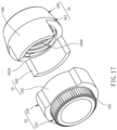
- FIG. 1 is a perspective view of a bicycle free-coaster hub disposed with a first embodiment of the disclosed driving mechanism
- FIG. 2 is a cross-sectional view taken along the direction 2 - 2 of FIG. 1 ;
- FIG. 3 is an exploded perspective view of the driving assembly and the input clutch unit of the first embodiment of the disclosed driving mechanism shown in FIG. 1 ;
- FIG. 4 is a combined perspective view of the driving assembly and the input clutch unit shown in FIG. 3 ;
- FIG. 5 is an exploded perspective view of the epicyclic gear assembly, the resisting member, the forward drag member and the reverse drag member of the first embodiment of the disclosed driving mechanism shown in FIG. 1 ;
- FIG. 6 is a combined perspective view of the sun gear and the ring gear, the cams and the forward drag member of the first embodiment of the disclosed driving mechanism shown in FIG. 1 ;
- FIG. 7 is a cross-sectional view taken along the direction 7 - 7 of FIG. 2 ;
- FIG. 8 is a cross-sectional view of a second embodiment of the disclosed driving mechanism wherein the cross-sectional direction is the same as that of FIG. 2 of the first embodiment;
- FIG. 9 is an exploded perspective view of the driving assembly and the input clutch unit of the second embodiment of the disclosed driving mechanism shown in FIG. 8 ;
- FIG. 10 is a combined perspective view of the driving assembly and the input clutch unit shown in FIG. 9 ;
- FIG. 11 is a cross-sectional view taken along the direction 11 - 11 of FIG. 8 ;
- FIG. 12 is a perspective view of the sun gear of the epicyclic gear assembly of the second embodiment of the disclosed driving mechanism shown in FIG. 8 ;
- FIG. 13 is a combined perspective view of the sun gear and the ring gear of the epicyclic gear assembly, the pawls of the input clutch unit and the forward drag member of the second embodiment of the disclosed driving mechanism shown in FIG. 8 ;
- FIG. 14 is a combined perspective view of the driving assembly and the input clutch unit of a third embodiment of the disclosed driving mechanism
- FIG. 15 is a combined perspective view of the driving assembly and the input clutch unit of a fourth embodiment of the disclosed driving mechanism
- FIG. 16 is a partial cross-sectional view of a fifth embodiment of the disclosed driving mechanism wherein the cross-sectional direction is the same as that of FIG. 2 of the first embodiment.
- FIG. 17 is an exploded perspective view of the clutch device and the sun gear of the fifth embodiment of the disclosed driving mechanism shown in FIG. 16 .
- reference number 900 shows a bicycle free-coaster hub disposed with a driving mechanism 100 of a first embodiment of the disclosure.
- the hub 900 includes a hub shell 901 and a hub axle 902 .
- the hub shell 901 is mounted on two bicycle frame elements 903 , as shown by the dotted line in FIG. 2 , by two hub bolts 904 .
- Each of the hub bolts 904 thread directly into the hub axle 902 such that two main-bearings 905 and a protective cover mechanism 906 are constrained to the shoulders 907 of the hub axle 902 by a plurality of hub sleeves 908 .
- the hub shell 901 is able to rotate smoothly about an axis X-X′ of the hub axle 902 .
- the hub 900 further has a cavity 909 defined by the hub shell 901 and the hub axle 902 .
- the driving mechanism 100 is disposed within the cavity 909 .
- the driving mechanism 100 comprises a driving assembly 10 , a clutch assembly 20 , an epicyclic gear assembly 30 , a resisting member 40 , a forward drag member 50 and a reverse drag member 70 .
- the driving assembly 10 comprises a sprocket 12 and a drive sleeve 14 .
- the sprocket 12 includes a plurality of sprocket teeth 120 projecting radially relative to the hub axle 902 .
- the drive sleeve 14 projects axially from the sprocket 12 and has a cylindrical axle hole 122 defined by the sprocket 12 and the drive sleeve 14 .
- the hub axle 902 passes through the axle hole 122 via a driver-bearing 910 so that the driving assembly 10 is rotated around the hub axle 902 .
- the clutch assembly 20 includes an output clutch unit 22 disposed on the cavity 909 of the hub 900 and an input clutch unit 24 coupled with the drive sleeve 14 to form a clutching or engaging state with the output clutch unit 22 .
- the epicyclic gear assembly 30 includes a sun gear 32 having a disk 320 and a gear portion 322 extending axially from the disk 320 , a ring gear 34 , a plurality of planet gears 36 and a planet gear carrier 38 .
- the output clutch unit 22 is a hub shell liner mounted on the inner wall 9010 of the hub shell 901 and having an engaged surface 220 , as shown in FIG. 7 , facing to the hub axle 902 .
- the input clutch unit 24 includes a plurality of cams 240 , a first cam receiver 242 , a second cam receiver 244 and a first retaining unit 246 .
- Each of the cams 240 has a first portion 2400 , a second portion 2402 , a concave arc inner surface 2404 and a roughened outer surface 2406 .
- the first cam receiver 242 includes a plurality of receiving rooms 2420 integrally and angularly arranged about the periphery of the drive sleeve 14 .
- Each of the receiving rooms 2420 includes a first ramp 2422 and a second ramp 2424 arranged symmetrically with the first ramp 2422 .
- Each of the ramps 2422 , 2424 has a first bottom portion 2426 and a first top portion 2428 . As shown in FIG. 7 , the radial distance d 1 between the first bottom 2426 and the hub axle 902 is smaller than the radial distance d 2 between the first top portion 2428 and the hub axle 902 .
- the first ramp 2422 and the second ramp 2424 are used to enable the drive assembly 10 to be assembled on the left or right side of the hub shell 901 .
- the first portion 2400 of each of the cams 240 is received in each of the receiving rooms 2420 in a way that the inner surface 2404 is in contact with the first ramp 2420 in a manner that can slide along the first ramp 2422 from the bottom portion 2426 to the top portion 2428 or the top portion 2428 to the bottom portion 2426 to enable the roughened outer surface 2406 to engage or disengage the engaged surface 220 of the hub shell liner 22 .
- the second cam receiver 244 includes a plurality of pockets 2440 disposed on the disk 320 of the sun gear 32 for receiving the second portion 2402 of each of the cams 240 so that each of the cams 240 can move with the sun gear 32 .
- the first retaining unit 246 includes a retaining piece 2460 and a coil-spring 2462 . The retaining piece 2460 is received in one of the receiving rooms 2420 and in contact with the second ramp 2424 thereof.
- the coil-spring 2462 has one end 2464 inserted into an inserted hole 2466 of the retaining piece 2460 and a coil body 2468 encircled on a first groove 2408 of each of the cams 240 and a second groove 2469 of the retaining piece 2460 respectively so that each of the cams 240 can be moved along the first ramp 2422 of each of the receiving rooms 2420 .
- the disk 320 of and the gear portion 322 of the sun gear 32 defines a first axle hole 324 for being passed therethrough by the hub axle 902 to allow the sun gear 32 to rotate therearound.
- the ring gear 34 is mounted on the inner wall 9010 of the hub shell 901 relative to the gear portion 322 of the sun gear 32 .
- the planet gear carrier 38 has a second axle hole 380 for being passed therethrough by the hub axle 902 to allow the planet gear carrier 38 to rotate therearound and a plurality of gear arms 382 .
- Each of the planet gears 36 is connected to each of the gear arms 382 in a way that it can rotate around each of the gear arms 382 and is engaged respectively with the ring gear 34 and the gear portion 322 of the sun gear 32 .
- the resisting member 40 in this embodiment, includes a wave spring 42 and a washer 44 .
- the wave spring 42 and the washer 64 are received in a recessed space 326 defined by the disk 320 of the sun gear 32 and a corresponding hub sleeve 908 so that the wave spring 42 is energized by the overall assembly of the hub 900 to the bicycle frames 903 by the hub bolts 904 to apply resistance to the rotation of the sun gear 32 .
- the forward drag member 50 in this embodiment, is a forward drag spring having a head end 52 , a tail end 54 and a helical body 56 .
- the helical body 56 encircles the disk 322 of the sun gear 32 in a forward direction from the head end 52 and the tail end 54 is inserted into an inserted hole 340 of the ring gear 34 so that the forward drag spring 50 can apply drag to the sun gear 32 when the hub 900 rotates forward.
- the reverse drag member 70 in this embodiment, as shown in FIG. 5 , includes a locating sleeve or liner 72 and a reverse drag spring 74 .
- the locating sleeve 72 includes an annular body 720 , an outer surface 722 and an inner surface 724 .
- the annular body 720 defines a third axle hole 726 for being passed therethrough by the hub axle 902 .
- the outer surface 722 has a ring edge 7220 engaging with an inner wall 384 of the planet gear carrier 38 and the inner surface 724 has a plurality of protrusions 7240 and elastic clips 7242 to tightly sleeve on the hub axle 902 via another corresponding hub sleeve 908 .
- the reverse drag spring 74 has a head end 742 , a tail end 744 and a helical body 746 .
- the helical body 746 encircles the outer surface 722 of the locating sleeve 72 in a reverse direction from the head end 742 and the tail end 744 is embedded on the planet gear carrier 38 so that the reverse drag spring 74 can apply drag to the planet gear carrier 38 when the hub rotates in reverse.
- the chain causes the driving assembly 10 to rotate forward (clockwise as viewed in FIG. 1 ).
- the cams 240 are initially restrained from moving forward by the sun gear 32 .
- the sun gear 32 is restrained from movement by the friction created by the forward drag member 50 .
- the driving assembly 10 advances relative to the cams 26
- the first ramp 2422 move against the inner surface 2404 to move the cams 240 radially outwards.
- the roughened outer surface 2406 come into contact with the engaged surface 220 of the hub shell liner 22 .
- Such a cam action produces a high contact force and the driving mechanism 100 becomes fully engaged with the wheel such that the bicycle is driven forwards, as shown by the arrow in FIG. 7 .
- the cams 240 are carried forward relative to the driving assembly 10 , initially by the hub shell liner 22 and then by the friction applied by the forward drag member 50 so that the cams 240 move down the first ramp 2422 and are no longer held out against the hub shell liner 22 and therefore the wheel is fully disengaged.
- the cams 240 are carried forward from the top portion 2428 to the bottom portion 2426 , the friction between the forward drag member 50 and the disk 320 is overwhelmed and the forward drag member 50 slips relative to the sun gear 32 . At this point, the bicycle will freewheel forward.
- the hub 900 rotates backward (anticlockwise as viewed in FIG. 7 ).
- the hub shell 901 , the hub shell liner 22 and the ring gear 34 move backward relative to the hub axle 902 .
- This backward movement will attempt to turn the planet gear carrier 38 backwards but this movement will be resisted by the reverse drag member 70 .
- the epicyclic gear assembly 30 will therefore be engaged and overwhelm the friction applied to the sung ear 32 , causing the sun gear 32 to rotate forwards.
- the pockets 2440 will carry the cams 240 forward and further away from engagement with the hub shell liner 22 .
- FIG. 8 to FIG. 13 show that the bicycle free-coaster hub 900 is disposed with a driving mechanism 200 of a second embodiment of the disclosure. It must be mentioned here that in the following description of the driving mechanism 200 , the same reference numbers are used for the same components as those of the driving mechanism 100 . The differences between the driving mechanism 200 and the driving mechanism 100 are as follows:
- FIG. 14 shows a combined perspective view of the driving assembly and the driven clutch unit of a driving mechanism 300 of a third embodiment of the disclosure.
- the driving mechanism 300 differs from the driving mechanism 200 in that it includes a third retaining unit 31 having a plurality of sheet-like springs 310 .
- Each of the sheet-like springs 310 has a proximal end 312 fixed on arc-shaped concave base 2522 of the pawl receiving room 2520 and a distal end 314 connected with the claw body 2502 of each of the pawls 250 to retain each of the pawls 250 in the first position.
- FIG. 15 shows a combined perspective view of the driving assembly and the driven clutch unit of a driving mechanism 400 of a fourth embodiment of the disclosure.
- the driving mechanism 400 differs from the driving mechanism 200 in that when the pawls 250 are made of metal materials, the driving mechanism 400 includes a fourth retaining unit 41 having a plurality of magnetic members 410 .
- Each of the magnetic members 410 is embedded in the ramp surface 2524 of each of the pawl receiving rooms 2520 to retain each of the pawls 250 in the first position by its magnetic force.
- the driving mechanism 500 differs from the driving mechanism 100 in that the driving mechanism 500 includes a clutch assembly 51 having an output clutch unit 53 and an input clutch unit 55 .
- the output clutch unit 53 in this embodiment, is also a hub shell liner having an inner cone surface 530 facing to the hub axle 902 .
- the input clutch unit 55 has a first clutch member 56 , a second clutch member 57 and a connecting member 58 .
- the first clutch member 56 includes a clutch portion 560 and a sleeve portion 562 extending axially from one end of the clutch portion 560 .
- the second clutch member 57 is an external threaded portion disposed on the drive sleeve 14 .
- the clutch portion 560 has a threaded hole 5600 for engagement with the second clutch member 57 so that the first clutch member 56 can be driven by the drive sleeve 14 to axially move along the hub axle 902 and an outer cone surface 5602 for cooperating with the inner conical surface 530 of the output clutch unit 53 to form a clutching or engaging state.
- the sleeve portion 562 has a through hole 5620 communicated with the threaded hole 5600 of the clutch portion 560 so that the hub axle 902 can pass through the input clutch unit 55 .
- the connecting member 58 includes two first engaging devices 580 symmetrically disposed on the sleeve portion 562 and two second engaging devices 582 symmetrically disposed on the disk 320 of the sun gear 32 to engage with the first engaging devices 580 so that the input clutch unit 55 can move linearly relative to the sun gear 32 or rotate with the sun gear 32 .
Landscapes
- Engineering & Computer Science (AREA)
- Mechanical Engineering (AREA)
- General Engineering & Computer Science (AREA)
- Chemical & Material Sciences (AREA)
- Combustion & Propulsion (AREA)
- Transportation (AREA)
- Retarders (AREA)
Abstract
Description
-
- the
driving mechanism 200 includes a clutch assembly 21 having an outputclutch unit 23 and an inputclutch unit 25. The outputclutch unit 23, in this embodiment, is also a hub shell liner having an engagedsurface 230 with a plurality ofratchet teeth 232 and aninclined surface 234 between twoadjacent ratchet teeth 232, as shown inFIG. 11 . the inputclutch unit 25 includes a plurality ofpawls 250, afirst pawl receiver 252, asecond pawl receiver 254 and asecond retaining unit 256. Each of thepawls 250 includes acylindrical root 2500 and aclaw body 2502 extending outward from thecylindrical root 2500. In this embodiment, thefirst pawl receiver 252 includes a plurality ofpawl receiving rooms 2520 integrally and angularly arranged about the periphery of thedrive sleeve 14. Each of thepawl receiving rooms 2520 has an arc-shapedconcave base 2522 and aramp surface 2524 extending outward from the arc-shapedconcave base 2522. Thesecond pawl receiver 254 includes a plurality of holdingrooms 2540 integrally and angularly arranged on thedisk 320 of thesun gear 32. In combination, a part of thecylindrical root 2500 is held in the arc-shapedconcave base 2522 and a part of theclaw body 2502 extends along aramp surface 2524 so that each of thepawls 250 can swing between a first position and a second position. Another part of thecylindrical root 2500 and another part of theclaw body 2502 are housed in theholding room 2540. Furthermore, each of theholding rooms 2540 has a raisedportion 2542 so that when thesun gear 32 moves forward, the raisedportion 2542 will exert an outward thrust to push each of thepawls 250 from the first position to the second position to engage with theratchet teeth 232 of the engagedsurface 230 of thehub shell liner 23. Thesecond retaining unit 256 is a coil-spring having oneend 2560 inserted into aninsert hole 142 of thedrive sleeve 14 and acoil body 2562 encircled on the outer surface of each of thepawls 250 to retain each of thepawls 250 in the first position.
- the
Claims (13)
Applications Claiming Priority (6)
| Application Number | Priority Date | Filing Date | Title |
|---|---|---|---|
| TW110131498A TWI777747B (en) | 2021-08-25 | 2021-08-25 | bicycle hub clutch |
| TW110131498 | 2021-08-25 | ||
| TW110212252U TWM624044U (en) | 2021-10-18 | 2021-10-18 | Bicycle hub clutch mechanism assembly |
| TW110212252 | 2021-10-18 | ||
| TW111203381 | 2022-04-01 | ||
| TW111203381U TWM638429U (en) | 2022-04-01 | 2022-04-01 | Pawl-type free-sliding clutch mechanism for bicycle hub |
Publications (2)
| Publication Number | Publication Date |
|---|---|
| US20230066122A1 US20230066122A1 (en) | 2023-03-02 |
| US12220943B2 true US12220943B2 (en) | 2025-02-11 |
Family
ID=85285493
Family Applications (1)
| Application Number | Title | Priority Date | Filing Date |
|---|---|---|---|
| US17/882,804 Active 2043-08-25 US12220943B2 (en) | 2021-08-25 | 2022-08-08 | Driving mechanism of bicycle free-coaster hub |
Country Status (1)
| Country | Link |
|---|---|
| US (1) | US12220943B2 (en) |
Families Citing this family (1)
| Publication number | Priority date | Publication date | Assignee | Title |
|---|---|---|---|---|
| CN116464721A (en) * | 2023-06-12 | 2023-07-21 | 邢台轩路自行车零配件有限公司 | Mute bicycle flywheel |
Citations (6)
| Publication number | Priority date | Publication date | Assignee | Title |
|---|---|---|---|---|
| US3995503A (en) * | 1974-05-29 | 1976-12-07 | Fichtel & Sachs A.G. | Multiple-speed hub |
| US4615423A (en) * | 1982-08-17 | 1986-10-07 | Fichtel & Sachs Ag | Hub for a two-wheeled vehicle |
| US20020179394A1 (en) * | 2001-05-31 | 2002-12-05 | Chin-Fu Wu | Clutch of hub of bicycle |
| US20120083383A1 (en) * | 2010-09-30 | 2012-04-05 | Sram Deutschland Gmbh | Hub with mechanism to permit backwards movement without pedal movement |
| US20170101161A1 (en) * | 2015-10-08 | 2017-04-13 | Alon Cohen | Bicycle drive mechanism to enable coasting |
| US20180045279A1 (en) * | 2015-02-27 | 2018-02-15 | Fxgear Co., Ltd. | Adjustable speed gear apparatus |
-
2022
- 2022-08-08 US US17/882,804 patent/US12220943B2/en active Active
Patent Citations (6)
| Publication number | Priority date | Publication date | Assignee | Title |
|---|---|---|---|---|
| US3995503A (en) * | 1974-05-29 | 1976-12-07 | Fichtel & Sachs A.G. | Multiple-speed hub |
| US4615423A (en) * | 1982-08-17 | 1986-10-07 | Fichtel & Sachs Ag | Hub for a two-wheeled vehicle |
| US20020179394A1 (en) * | 2001-05-31 | 2002-12-05 | Chin-Fu Wu | Clutch of hub of bicycle |
| US20120083383A1 (en) * | 2010-09-30 | 2012-04-05 | Sram Deutschland Gmbh | Hub with mechanism to permit backwards movement without pedal movement |
| US20180045279A1 (en) * | 2015-02-27 | 2018-02-15 | Fxgear Co., Ltd. | Adjustable speed gear apparatus |
| US20170101161A1 (en) * | 2015-10-08 | 2017-04-13 | Alon Cohen | Bicycle drive mechanism to enable coasting |
Also Published As
| Publication number | Publication date |
|---|---|
| US20230066122A1 (en) | 2023-03-02 |
Similar Documents
| Publication | Publication Date | Title |
|---|---|---|
| EP1413509B1 (en) | Bicycle hub transmission | |
| US5964332A (en) | Rear hub drive engagement mechanism | |
| US4593799A (en) | One way clutch mechanism for bicycle freewheel hub | |
| US7682283B2 (en) | Bicycle hub transmission with a power control mechanism for a shift assist mechanism | |
| US6641500B2 (en) | Bicycle hub transmission with a power control mechanism for a shift assist mechanism | |
| US8376897B2 (en) | Internally geared hub for bicycle | |
| US20170101161A1 (en) | Bicycle drive mechanism to enable coasting | |
| US5961416A (en) | Internally mounted bicycle transmission | |
| CA2303686C (en) | Freewheel clutch | |
| US20020183159A1 (en) | Internal transmission device with automatic shift mechanism for a bicycle | |
| US4059028A (en) | Multiple speed hub with coaster brake | |
| US5027930A (en) | Coaster brake assembly | |
| KR100195515B1 (en) | Control device of bicycle forward change drive | |
| US12220943B2 (en) | Driving mechanism of bicycle free-coaster hub | |
| US6010425A (en) | Automatic bicycle hub transmission using flyweights | |
| US11226016B1 (en) | Automatic free-coasting freewheel apparatus | |
| US6325739B1 (en) | Bicycle hub transmission with a mechanism for stopping rotation of one or more sun gears relative to another member | |
| TWM624044U (en) | Bicycle hub clutch mechanism assembly | |
| US6361461B1 (en) | Multiple-speed chain driving device | |
| TWI777747B (en) | bicycle hub clutch | |
| US5810139A (en) | Bicycle and a friction device for controlling a clamping roller coupling of a bicycle hub of a bicycle | |
| KR20010110061A (en) | Apparatus for controlling a speed changing apparatus for bicycles | |
| US4119182A (en) | Two-speed bicycle hub with coaster brake and pedal actuated speed shift | |
| TWM638429U (en) | Pawl-type free-sliding clutch mechanism for bicycle hub | |
| US20250033408A1 (en) | Mechanical assembly to disengage a bicycle rear hub with a pawl and ratchet-ring clutch mechanism |
Legal Events
| Date | Code | Title | Description |
|---|---|---|---|
| AS | Assignment |
Owner name: BEAR CORPORATION, CALIFORNIA Free format text: ASSIGNMENT OF ASSIGNORS INTEREST;ASSIGNOR:FRENCH, GEORGE;REEL/FRAME:060742/0483 Effective date: 20220804 Owner name: TEDDY FORMOSA CO., LTD., TAIWAN Free format text: ASSIGNMENT OF ASSIGNORS INTEREST;ASSIGNOR:FRENCH, GEORGE;REEL/FRAME:060742/0483 Effective date: 20220804 |
|
| FEPP | Fee payment procedure |
Free format text: ENTITY STATUS SET TO UNDISCOUNTED (ORIGINAL EVENT CODE: BIG.); ENTITY STATUS OF PATENT OWNER: SMALL ENTITY |
|
| FEPP | Fee payment procedure |
Free format text: ENTITY STATUS SET TO SMALL (ORIGINAL EVENT CODE: SMAL); ENTITY STATUS OF PATENT OWNER: SMALL ENTITY |
|
| STPP | Information on status: patent application and granting procedure in general |
Free format text: DOCKETED NEW CASE - READY FOR EXAMINATION |
|
| STPP | Information on status: patent application and granting procedure in general |
Free format text: NOTICE OF ALLOWANCE MAILED -- APPLICATION RECEIVED IN OFFICE OF PUBLICATIONS |
|
| ZAAB | Notice of allowance mailed |
Free format text: ORIGINAL CODE: MN/=. |
|
| STPP | Information on status: patent application and granting procedure in general |
Free format text: PUBLICATIONS -- ISSUE FEE PAYMENT VERIFIED |
|
| STCF | Information on status: patent grant |
Free format text: PATENTED CASE |