US12220809B2 - Sensing device and robot manipulator having the same - Google Patents
Sensing device and robot manipulator having the same Download PDFInfo
- Publication number
- US12220809B2 US12220809B2 US17/640,388 US202017640388A US12220809B2 US 12220809 B2 US12220809 B2 US 12220809B2 US 202017640388 A US202017640388 A US 202017640388A US 12220809 B2 US12220809 B2 US 12220809B2
- Authority
- US
- United States
- Prior art keywords
- cover
- force
- force sensor
- robot manipulator
- sensing device
- Prior art date
- Legal status (The legal status is an assumption and is not a legal conclusion. Google has not performed a legal analysis and makes no representation as to the accuracy of the status listed.)
- Active, expires
Links
- 230000014509 gene expression Effects 0.000 claims description 62
- 239000000463 material Substances 0.000 claims description 9
- 239000012636 effector Substances 0.000 claims description 7
- 238000000034 method Methods 0.000 description 14
- 230000036555 skin type Effects 0.000 description 8
- 230000008569 process Effects 0.000 description 5
- 230000006870 function Effects 0.000 description 4
- 230000008859 change Effects 0.000 description 3
- 230000003247 decreasing effect Effects 0.000 description 3
- 238000004519 manufacturing process Methods 0.000 description 3
- 238000000926 separation method Methods 0.000 description 3
- 238000009825 accumulation Methods 0.000 description 2
- 238000009826 distribution Methods 0.000 description 2
- 238000003466 welding Methods 0.000 description 2
- 230000008901 benefit Effects 0.000 description 1
- 230000005540 biological transmission Effects 0.000 description 1
- 239000011159 matrix material Substances 0.000 description 1
- 238000012986 modification Methods 0.000 description 1
- 230000004048 modification Effects 0.000 description 1
- 239000004065 semiconductor Substances 0.000 description 1
Images


Classifications
-
- B—PERFORMING OPERATIONS; TRANSPORTING
- B25—HAND TOOLS; PORTABLE POWER-DRIVEN TOOLS; MANIPULATORS
- B25J—MANIPULATORS; CHAMBERS PROVIDED WITH MANIPULATION DEVICES
- B25J13/00—Controls for manipulators
- B25J13/08—Controls for manipulators by means of sensing devices, e.g. viewing or touching devices
- B25J13/081—Touching devices, e.g. pressure-sensitive
-
- B—PERFORMING OPERATIONS; TRANSPORTING
- B25—HAND TOOLS; PORTABLE POWER-DRIVEN TOOLS; MANIPULATORS
- B25J—MANIPULATORS; CHAMBERS PROVIDED WITH MANIPULATION DEVICES
- B25J13/00—Controls for manipulators
- B25J13/08—Controls for manipulators by means of sensing devices, e.g. viewing or touching devices
- B25J13/085—Force or torque sensors
-
- B—PERFORMING OPERATIONS; TRANSPORTING
- B25—HAND TOOLS; PORTABLE POWER-DRIVEN TOOLS; MANIPULATORS
- B25J—MANIPULATORS; CHAMBERS PROVIDED WITH MANIPULATION DEVICES
- B25J17/00—Joints
-
- B—PERFORMING OPERATIONS; TRANSPORTING
- B25—HAND TOOLS; PORTABLE POWER-DRIVEN TOOLS; MANIPULATORS
- B25J—MANIPULATORS; CHAMBERS PROVIDED WITH MANIPULATION DEVICES
- B25J19/00—Accessories fitted to manipulators, e.g. for monitoring, for viewing; Safety devices combined with or specially adapted for use in connection with manipulators
- B25J19/0075—Means for protecting the manipulator from its environment or vice versa
-
- B—PERFORMING OPERATIONS; TRANSPORTING
- B25—HAND TOOLS; PORTABLE POWER-DRIVEN TOOLS; MANIPULATORS
- B25J—MANIPULATORS; CHAMBERS PROVIDED WITH MANIPULATION DEVICES
- B25J19/00—Accessories fitted to manipulators, e.g. for monitoring, for viewing; Safety devices combined with or specially adapted for use in connection with manipulators
- B25J19/02—Sensing devices
-
- G—PHYSICS
- G01—MEASURING; TESTING
- G01L—MEASURING FORCE, STRESS, TORQUE, WORK, MECHANICAL POWER, MECHANICAL EFFICIENCY, OR FLUID PRESSURE
- G01L5/00—Apparatus for, or methods of, measuring force, work, mechanical power, or torque, specially adapted for specific purposes
- G01L5/22—Apparatus for, or methods of, measuring force, work, mechanical power, or torque, specially adapted for specific purposes for measuring the force applied to control members, e.g. control members of vehicles, triggers
Definitions
- the present disclosure of invention relates to a sensing device and a robot manipulator having the sensing device, and more specifically the present disclosure of invention relates to a sensing device and a robot manipulator having the sensing device, capable of detecting magnitude, a direction and a position of a force for entire area of a cover, using a single force sensor measuring the force and a torque.
- a robot manipulator is widely used in an industrial field such as a vehicle manufacturing factory, a semiconductor manufacturing factory and so on, and the robot manipulator includes multiple joints and a tool equipped at an end, for performing a predetermined process.
- the efficiency of the process may be increased and the process at an extreme environment may be easily performed, by the robot manipulator.
- the safety in the process is the most important issue.
- a sensor is attached to the robot manipulator and a force applied to the robot manipulator is measured, so that the operation of the robot manipulator may be controlled safely.
- FIG. 1 is a schematic view illustrating a conventional robot manipulator having a sensing system configured to measure an external force.
- the sensing methods for measuring the force applied to a joint link 120 are as follows in two ways.
- a torque sensor 140 is equipped to a joint 130 between the joint links 120 adjacent to each other, to measure a force applied to the joint link 120 .
- the torque sensor 140 is equipped to each joint 130 , and thus an impact of the robot manipulator 10 may be detected and the external force applied to the robot manipulator 10 may be measured.
- the torque sensor 140 should be linearly equipped to an actuator (not shown) formed at the joint 130 , and thus a joint module should be designed complicatedly and cost may be increased. Further, a relatively small error occurring in the torque sensor 140 of a start joint 130 a makes a relatively large error at an end due to error accumulation. Here, to minimize the error accumulation, a relatively expensive torque sensor having fine accuracy and high stiffness should be used.
- a skin type film sensor 150 covering each joint link 120 is used.
- a flexible skin type film sensor 150 is attached to a surface of the joint link 120 , and thus magnitude, a position and a distribution of the force applied to the joint link 120 may be measured. However directions of the force applied to the joint can not be measured with this method.
- both the magnitude of the force and the position and the distribution of the force are obtained at the same time and the film sensor 150 may be useful.
- a plurality of sensor nodes are arranged over an entire surface of the film sensor, and thus the number of the sensor nodes are increased and a wiring is complicated.
- a high sensitive and expensive sensor is hard to be used, so that reliability of the sensing results may be decreased.
- the present invention is developed to solve the above-mentioned problems of the related arts.
- the present invention provides a sensing device capable of detecting magnitude, a direction and a position of a force applied to an arbitrary position of a cover, using a single force sensor which measures the force and a torque and is disposed at a position of an entire surface between a body of various kinds of structures and the cover covering the body.
- the present invention also provides a robot manipulator having the sensing device.
- a sensing device includes a cover, a force sensor and a force information calculating part.
- the cover has a predetermined shape and is configured to cover a body.
- Robot can use multiple number of the present invention to cover whole robot areas.
- the force sensor is disposed at a position between the body and the cover, and is configured to measure a force and a torque applied via the cover at the position.
- the force information calculating part is configured to obtain an information on the force applied to the cover from data measured by the force sensor, when the force is applied to an arbitrary position of the cover.
- the force information calculating part may be configured to obtain the information of the force applied to the cover, by using an information on the predetermined shape of the cover in addition to the data measured by the force sensor.
- the arbitrary position of the cover may be defined by a predetermined expression with respect to the position at which the force sensor is disposed.
- the force (f) and the torque (q) measured by the force sensor may have a geometric locational relation with the applied force (p) and the position (c) of the cover at which the force is applied.
- the cover may have a rigid material, and the cover may have the predetermined shape such as a plane shape, a partial cylindrical shape, a partial spherical shape and a curved shape.
- the body may be one of a robot, a mobile device, a game device, a display and a smart device.
- the force sensor may be disposed at each cover.
- a robot manipulator includes a cover, a force sensor and a force information calculating part.
- the cover has a predetermined shape and is configured to cover a body of a robot.
- the force sensor is disposed at a position between the body and the cover, and is configured to measure a force and a torque.
- the force information calculating part is configured to obtain an information on the force applied to an arbitrary position of the cover from data measured by the force sensor and an information on the shape of the cover.
- the force sensor may be a 6-axis force sensor measuring forces and torques along three directions perpendicular to one another.
- the body may be formed with a plurality of joint links.
- the cover may be divided into a plural to cover the joint link, and the force sensor may be disposed at each divided cover.
- the cover may be divided into the plural along an axis circumferential direction of the joint link.
- a plane surface may be formed in an inner surface of the cover to form a contact portion making contact with a horizontal surface of the force sensor.
- the information of the force may include at least one of magnitude of the force, a direction of the force and a position of the force.
- the cover may have a rigid material, and the force sensor may be disposed at each cover.
- the robot manipulator may further include a joint link configured to form a robot joint, a joint disposed between the joint links adjacent to each other, and an end effector formed at an end of the joint link.
- the body may be the joint link.
- the force applied to the arbitrary position on the cover may be easily and effectively detected by the single force sensor which is disposed at a position of an entire surface between the cover and the body of the structure such as the robot.
- the direction of the force applied to the cover may be also measured in addition to the magnitude and position of the force.
- the number of the wiring is decreased and thus the wiring may be easily formed and arranged.
- the torque sensor is unnecessary to be equipped at the joint, the structure of the joint may be more simplified.
- the sensing device may be easily manufactured by using the cover having the rigid material conventionally used for protecting an inside of the structure such as the robot.
- FIG. 1 is a schematic view illustrating a conventional robot manipulator having a sensing system configured to measure an external force
- FIG. 2 is a schematic view illustrating a robot manipulator having a sensing device according to an example embodiment of the present invention
- FIG. 3 is a cross-sectional view showing a portion ‘A’ of FIG. 2 ;
- FIG. 4 A and FIG. 4 B are cross-sectional views illustrating a joint link
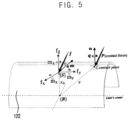
- FIG. 5 is a schematic view illustrating a directional relation and a position relation between a force measured by a force sensor disposed under a cover and a force actually applied to the cover.
- robot manipulator 110 base 120: joint link 122: cover 123: contact portion 130: joint 140: torque sensor 150: skin type film sensor 160: end effector 170: force sensor
- FIG. 2 is a schematic view illustrating a robot manipulator having a sensing device according to an example embodiment of the present invention.
- FIG. 3 is a cross-sectional view showing a portion ‘A’ of FIG. 2 .
- FIG. 4 A and FIG. 4 B are cross-sectional views illustrating a joint link.
- the sensing device includes a cover 122 , a force sensor 170 and a force information calculating part (not shown).
- the sensing device may be equipped to an outer shape of a structure such as a robot having a predetermined body, and may be further equipped to the outer shape of various kinds of structures, and the structure is not limited to a robot manipulator explained below.
- the sensing device is explained to be equipped to the robot, and the robot manipulator 100 is explained as a representative example to which the sensing device is equipped.
- the robot manipulator 100 may include the cover 122 , the force sensor 170 and the force information calculating part (not shown).
- the robot manipulator 100 includes a joint link 120 , a joint 130 and an end effector 160 which are included in the conventional robot manipulator, and the above conventional components, the robot manipulator 100 according to the present example embodiment further includes the cover 122 , the force sensor 170 and the force information calculating part.
- the joint link 120 is a plural, and the plurality of joint links 120 is serially connected from a base 110 forming a fixing portion, to form a robot joint similar with a human joint.
- the joint 130 is formed between the base 110 and the joint link 120 or between the joint links 120 adjacent to each other, and an actuator (not shown) is formed at the joint 130 to perform various kinds of actions.
- the joint link 120 may be rotated with respect to the joint 130 , may be rotated with respect to an axis of the joint link 120 , or may be linearly driven using a cylindrical type actuator.
- various kinds of robot manipulators 100 having multiple degrees of freedom may be manufactured by applying various kinds of designing methods such as the change of the number of the joint links 120 , the change of the design of the actuator at the joint, and so on.
- the end effector 160 is formed at an end of the endmost joint link 120 , and various kinds of end effectors 160 may be equipped considering required functions such as gripping, welding, assembling, and so on.
- the cover 122 covers an outer surface of the joint link 120 .
- a predetermined separation space is formed between the joint link 120 and the cover 122 , and the force sensor 170 may be disposed in the separation space.
- a plurality of the covers 122 which is separated with each other may cover an entire outer surface of the joint link 120 , and each force sensor 170 may be disposed in each separation space formed between the joint link 120 and each of the covers 122 . That is, the cover 122 covering the outer surface of each joint link 120 may be divided into a plural.
- the plurality of the covers 122 separated with each other covers the outer surface of the single joint link 120 , as illustrated in FIG. 4 A .
- the plurality of covers 122 may cover the entire surface of the joint link 120 along an axis circumferential direction of the joint link 120 . In FIG.
- FIG. 4 A three covers 122 spaced with each other by 120° are disposed along the axis circumferential direction of the joint link 120 , for covering the joint link 120 .
- FIG. 4 B four covers 122 spaced with each other by 90° are disposed along the axis circumferential direction of the joint link 120 , for covering the joint link 120 .
- the method for covering the single joint link 120 using the plurality of covers 122 may not be limited to the above mentioned methods, and may be variously changed. Further, the number of the covers 122 is not limited thereto, the shape of each of the covers 122 may be changed variously, and the distance between the covers 122 may also be changed variously. However, for the convenience of the manufacturing, the number of the divided covers may be properly controlled.
- the divided covers 122 adjacent to each other for the single joint link 120 may be separated with each other and may not be interfered.
- a single force sensor 170 is disposed between the divided cover 122 and the joint link 120 , and each force sensor 170 measures the force applied to each cover 122 making contact with each force sensor 170 .
- the specific force sensor 170 measuring the force applied to the specific cover 122 is not affected by the force applied to other cover 122 .
- the cover 122 covers the joint link 120 disposed inside of the cover 122 , a power transmission (not shown), an electric circuit (not shown), a wiring (not shown) and so on, and also covers the outer surface.
- the outer surface of the device may look clean and neat.
- the cover 122 covers the joint link 120 in addition to the wiring as mentioned above, and the cover 122 transmits the force applied at an arbitrary position of the cover 122 to the force sensor 170 .
- the cover 122 may include a rigid material.
- the cover 122 has a predetermined shape, which means that the shape of the cover 122 is not changed or the shape of the cover 122 is restored to an original shape once changed.
- the arbitrary position of the cover 122 may be defined as a predetermined expression with respect to a specific reference point or position.
- the arbitrary position of the cover 122 may be defined as the predetermined expression with respect to the position at which the force sensor 170 is disposed.
- the expression may include various kinds of geometrical functions and may be defined variously according to the shape of the cover 122 .
- the expression may be a plane function defining the extending plane of the cover 122 .
- an arbitrary position of the cover 122 may be defined as a predetermined geometrical function, with respect to a predetermined defined reference position of the cover.
- the cover 122 may have a plane shape, a partial cylindrical shape, a partial spherical shape, a curved shape and so on.
- the force sensor 170 is disposed at an arbitrary position of an entire surface between the joint link 120 and the cover 122 covering the joint link 120 , to measure a force and a moment transmitted from the cover 122 .
- single force sensor 170 may be disposed at the arbitrary position mentioned above.
- the force sensor 170 is disposed between an upper portion of the joint link 120 and a lower portion of the cover 122 , and the single force sensor 170 is disposed at the position of the entire surface between the joint link 120 and the cover 122 .
- a skin type film sensor disposed all over the entire surface of the joint link 120 is not used in the present example embodiment.
- the force sensor 170 may be disposed at a center of the cover 122 .
- the force sensor 170 measures the force and the moment transmitted to the cover 122 which has a rigid material.
- the force information calculating part calculates a force information including magnitude, a direction and a position of the force actually applied to the cover 122 , based on the force and the moment measured by the force sensor 170 .
- a contact portion 123 is formed at the cover 122 , so that the cover 122 may contact with an upper horizontal surface of the force sensor 170 easily.
- the contact portion 123 forms a plane surface on an inner surface of the cover 122 having a curved surface.
- the force sensor 170 measures the force and the moment at the same time, and thus the force sensor 170 may be a multi-axis force sensor having three axes or six axes.
- the force sensor 170 may be the six-axis force sensor measuring a three-axis direction force (f x , f y , f z ) and a three-axis direction torque (m x , m y , m z ).
- the six-axis force sensor 170 disposed between the cover 122 and the joint link 120 measures the three-axis direction force and the three-axis direction torque applied to the force sensor 170 , as the force is applied to the arbitrary position of the cover 122 due to an external impact and so on.
- the force information calculating part calculates the magnitude, the direction and the position of the force applied to the cover 122 , based on the force and the torque measured by the force sensor 170 .
- the geometrical information on the shape of the cover 122 is obtained, the geometrical relation between the six-axis values mentioned above measured by the force sensor 170 and the force applied to the surface of the cover 122 may be obtained.
- the force information calculating part may obtain or calculate the magnitude, the direction, and the position of the force applied to the cover 122 fast and accurately, using the forces and torques measured by the force sensor 170 and the geometrical shape of the cover 122 .
- the six-axis data are measured by the six-axis force sensor 170 and the geometrical shape of the cover 122 is obtained, and then the magnitude, the direction and the position of the force applied to the cover 122 is easily obtained.
- the number of the information on the force applied to the cover 122 may change as the number of the data measured by the force sensor 170 changes.
- the force information calculating part may include a memory storing the data and a calculating part like a CPU calculating the data.
- the robot manipulator 100 may be operated by a controller (not shown). For example, the magnitude of the force applied to the cover 122 is larger than a predetermined value, the controller may control the robot manipulator 110 to be automatically stopped or to move along alternative path.
- the cover 122 covering the joint link 120 is divided into a plural spaced apart from each other, and the force sensor 170 is disposed between each divided cover 122 and the joint link 120 . As the number of the divided covers increases, the information of the force applied to the joint link 120 may be obtained more accurately.
- FIG. 5 is a schematic view illustrating a directional relation and a position relation between a force measured by a force sensor disposed under a cover and a force applied to the cover.
- a surface S in FIG. 5 has a cylindrical shape having a radius r 0 and an axis parallel with a y axis.
- ⁇ has a limiting value as ⁇ .
- the force f measured by the force sensor 170 is expressed as a three-axis contact force p.
- the moment m measured by the force sensor 170 is related to the torque q, the contact position c, and the three-axis contact force p.
- the force f and the torque q measured by the force sensor 170 have a geometrical locational relation among the applied force p and the position c of the cover to which the force is applied.
- the force-moment equilibrium equations are expressed by Expression (3) and Expression (4).
- a normal vector n of the surface is expressed by Expression (6).
- the axis is a line passing through r 0 , and is expressed by Expression (13) and Expression (14).
- f which is parameterized by ⁇ is parallel with the axis.
- K is obtained from Expression (16).
- K 4 D 2 r 0 2 +K 2 [r 0 2 ⁇ Af ⁇ 2 ⁇ D 2 ⁇ A ⁇ 1 m′ ⁇ 2 ] ⁇ ( f T m ′) 2 0.
- the geometrical relationship is defined, and the three-axis external force p and the contact positon c of the surface are expressed by the force f and m measured by the force sensor 170 . Accordingly, from the geometrical shape of the cover 122 and the measured data of the force and the torque by the force sensor 170 , the force information including the magnitude, the direction and the position of the force actually applied to the cover 122 is obtained.
- the robot manipulator 100 having the sensing device is explained, but as mentioned above, the sensing device may be configured to various kinds of structures except for the robot manipulator.
- the cover 122 is disposed to cover the body of the robot, and further may be disposed or equipped to various kinds of structures such as a robot body, a mobile device, a game device, a display like a television, a smart device and so on.
- the robot manipulator includes a first joint 130 between the base 110 and the joint link 120 , and the controller (not shown) controls the actuator (not shown) equipped to the joint 130 disposed between the joint links 120 adjacent to each other, so that the robot manipulator performs joint movements and the end effector 160 connected to the end joint link 120 performs an operation of gripping the object, welding, assembling and so on.
- the force sensor 170 disposed at the position between the cover 122 and the joint link 120 measures the force and the torque transmitted from the cover 122 having the rigid material.
- the force sensor 170 is the six-axis force sensor 170 measuring the three-axis force and the three-axis torque, and thus the force information calculating part (not shown) obtains the information on the magnitude, the direction and the position of the force applied to the arbitrary position of the cover 122 using the measured data from the force sensor 170 and the geometrical shape of the cover 122 .
- the relation equation matching the relationship between the geometrical shape of the cover 122 and the force applied to the surface of the cover 122 from the measured data from the force sensor 170 is used, to obtain the magnitude, the direction and the position of the force applied to the cover 122 fast and accurately.
- the controller controls the operation of the robot manipulator 100 .
- the robot manipulator having a plurality of joint links 120 is explained as an example, but the example mentioned above may be applied to any of normal robot bodies forming an outer shape of the robot having the joint link 120 .
- the force applied to the arbitrary position on the cover may be easily and effectively detected by the single force sensor which is disposed at a position of an entire surface between the cover and the body of the structure such as the robot.
- the direction of the force applied to the cover may be also measured in addition to the magnitude and position of the force.
- the number of the wiring is decreased and thus the wiring may be easily formed and arranged.
- the torque sensor is unnecessary to be equipped at the joint, the structure of the joint may be more simplified.
- the sensing device may be easily manufactured by using the cover having the rigid material conventionally used for protecting an inside of the structure such as the robot.
Landscapes
- Engineering & Computer Science (AREA)
- Robotics (AREA)
- Mechanical Engineering (AREA)
- Human Computer Interaction (AREA)
- Physics & Mathematics (AREA)
- General Physics & Mathematics (AREA)
- Force Measurement Appropriate To Specific Purposes (AREA)
- Manipulator (AREA)
Abstract
Description
| * Reference numerals |
| 100: robot manipulator | 110: base | ||
| 120: joint link | 122: cover | ||
| 123: contact portion | 130: joint | ||
| 140: torque sensor | 150: skin type film sensor | ||
| 160: end effector | 170: force sensor | ||
S(r)=r T A T Ar−r 0 2=0 Expression (1)
f=p Expression (3)
m=q+(c−x 0)×p Expression (4)
m′=q+c×p Expression (5)
q=KA2c Expression (7)
m′=KA 2 c+c×f. Expression (8)
Γ(K)c=m′ Expression (9)
cTA2c=r0 2 Expression (10)
c=r 0 +λf Expression (12)
K 4 D 2 r 0 2 +K 2 [r 0 2 ∥Af∥ 2 −D 2 ∥A −1 m′∥ 2]−(f T m′)2=0. Expression (16)
D=det(A),σD 2 ∥A −1 m′∥ 2 −R 2 ∥Af∥ 2 Expression (17)
limγ→∞σ=(m′ 1)2 −r 0 2(f 2 2 +f 3 2) Expression (20)
K 2σ−(f T m′)2=0 Expression (21)
Claims (17)
Applications Claiming Priority (3)
| Application Number | Priority Date | Filing Date | Title |
|---|---|---|---|
| KR10-2019-0126391 | 2019-10-11 | ||
| KR1020190126391A KR102791357B1 (en) | 2019-10-11 | 2019-10-11 | Structure for sensing external force applied to robot |
| PCT/KR2020/001673 WO2021071030A1 (en) | 2019-10-11 | 2020-02-05 | Sensing device and robot manipulator comprising same |
Publications (2)
| Publication Number | Publication Date |
|---|---|
| US20220331977A1 US20220331977A1 (en) | 2022-10-20 |
| US12220809B2 true US12220809B2 (en) | 2025-02-11 |
Family
ID=75437197
Family Applications (1)
| Application Number | Title | Priority Date | Filing Date |
|---|---|---|---|
| US17/640,388 Active 2041-03-22 US12220809B2 (en) | 2019-10-11 | 2020-02-05 | Sensing device and robot manipulator having the same |
Country Status (3)
| Country | Link |
|---|---|
| US (1) | US12220809B2 (en) |
| KR (1) | KR102791357B1 (en) |
| WO (1) | WO2021071030A1 (en) |
Families Citing this family (2)
| Publication number | Priority date | Publication date | Assignee | Title |
|---|---|---|---|---|
| KR102457268B1 (en) * | 2021-06-03 | 2022-10-20 | 주식회사 피치랩 | Safety impactk apparatus for robot |
| KR102594841B1 (en) | 2022-03-02 | 2023-10-30 | 재단법인대구경북과학기술원 | System and method for measuring external force of robot |
Citations (10)
| Publication number | Priority date | Publication date | Assignee | Title |
|---|---|---|---|---|
| US5513106A (en) | 1991-12-20 | 1996-04-30 | Honda Giken Kogyo Kabushiki Kaisha | System for controlling locomotion of a walking robot having a sensor for detecting externally exerted forces |
| KR100753557B1 (en) | 2006-08-23 | 2007-08-30 | 삼성물산 주식회사 | Interface device of the working robot |
| KR20160146979A (en) | 2014-05-28 | 2016-12-21 | 엑스 디벨롭먼트 엘엘씨 | Robotic devices with ambient indications of joint status |
| US20170312921A1 (en) | 2016-04-28 | 2017-11-02 | Seiko Epson Corporation | Robot and robot system |
| US20180065256A1 (en) * | 2016-09-08 | 2018-03-08 | Fanuc Corporation | Human-collaborative robot |
| US20180079090A1 (en) * | 2016-09-16 | 2018-03-22 | Verb Surgical Inc. | Robotic arms |
| US20190248030A1 (en) * | 2016-10-31 | 2019-08-15 | Life Robotics Inc. | Robot arm mechanism |
| KR20190120838A (en) | 2018-04-12 | 2019-10-25 | 한국기계연구원 | Robot manipulator |
| US20210197381A1 (en) * | 2017-10-26 | 2021-07-01 | Comau S.P.A. | Automated Device With A Sensorized Covered Movable Structure, In Particular A Robot |
| US20220203563A1 (en) * | 2019-02-06 | 2022-06-30 | Kuka Deutschland Gmbh | Robot having at least one covering and at least one contact sensor |
Family Cites Families (3)
| Publication number | Priority date | Publication date | Assignee | Title |
|---|---|---|---|---|
| KR101665543B1 (en) * | 2009-08-12 | 2016-10-13 | 삼성전자 주식회사 | Tabilization apparatus for humanoid robot and method thereof |
| KR101481241B1 (en) * | 2012-12-27 | 2015-01-12 | 현대자동차주식회사 | Method and system for controlling walking of robot |
| KR101793139B1 (en) * | 2015-11-27 | 2017-11-03 | 한국기계연구원 | Skin assembly for robot and Robot using the same |
-
2019
- 2019-10-11 KR KR1020190126391A patent/KR102791357B1/en active Active
-
2020
- 2020-02-05 US US17/640,388 patent/US12220809B2/en active Active
- 2020-02-05 WO PCT/KR2020/001673 patent/WO2021071030A1/en not_active Ceased
Patent Citations (11)
| Publication number | Priority date | Publication date | Assignee | Title |
|---|---|---|---|---|
| US5513106A (en) | 1991-12-20 | 1996-04-30 | Honda Giken Kogyo Kabushiki Kaisha | System for controlling locomotion of a walking robot having a sensor for detecting externally exerted forces |
| KR100753557B1 (en) | 2006-08-23 | 2007-08-30 | 삼성물산 주식회사 | Interface device of the working robot |
| KR20160146979A (en) | 2014-05-28 | 2016-12-21 | 엑스 디벨롭먼트 엘엘씨 | Robotic devices with ambient indications of joint status |
| US20170312921A1 (en) | 2016-04-28 | 2017-11-02 | Seiko Epson Corporation | Robot and robot system |
| US20180065256A1 (en) * | 2016-09-08 | 2018-03-08 | Fanuc Corporation | Human-collaborative robot |
| JP2018039086A (en) | 2016-09-08 | 2018-03-15 | ファナック株式会社 | Human cooperative type robot |
| US20180079090A1 (en) * | 2016-09-16 | 2018-03-22 | Verb Surgical Inc. | Robotic arms |
| US20190248030A1 (en) * | 2016-10-31 | 2019-08-15 | Life Robotics Inc. | Robot arm mechanism |
| US20210197381A1 (en) * | 2017-10-26 | 2021-07-01 | Comau S.P.A. | Automated Device With A Sensorized Covered Movable Structure, In Particular A Robot |
| KR20190120838A (en) | 2018-04-12 | 2019-10-25 | 한국기계연구원 | Robot manipulator |
| US20220203563A1 (en) * | 2019-02-06 | 2022-06-30 | Kuka Deutschland Gmbh | Robot having at least one covering and at least one contact sensor |
Non-Patent Citations (1)
| Title |
|---|
| International Search Report issued Jul. 7, 2020, corresponding to International Application No. PCT/KR2020/001673. |
Also Published As
| Publication number | Publication date |
|---|---|
| KR20210043795A (en) | 2021-04-22 |
| US20220331977A1 (en) | 2022-10-20 |
| KR102791357B1 (en) | 2025-04-09 |
| WO2021071030A1 (en) | 2021-04-15 |
Similar Documents
| Publication | Publication Date | Title |
|---|---|---|
| Nguyen | Constructing stable grasps | |
| US11077547B2 (en) | Parallel mechanism with kinematically redundant actuation | |
| Zhang et al. | Vision-based sensing of external forces acting on soft robots using finite element method | |
| Dollar et al. | Joint coupling design of underactuated grippers | |
| JP7192292B2 (en) | Robot and robot anomaly detection method | |
| Rimon et al. | The Mechanics of Robot Grasping | |
| Hsu et al. | On grasping and coordinated manipulation by a multifingered robot hand | |
| Kim et al. | A novel intrinsic force sensing method for robot manipulators during human–robot interaction | |
| US12220809B2 (en) | Sensing device and robot manipulator having the same | |
| Sim et al. | Collision detection and safe reaction algorithm for non-backdrivable manipulator with single force/torque sensor | |
| KR102076907B1 (en) | Robot manipulator | |
| Tian et al. | Multi-tap resistive sensing and fem modeling enables shape and force estimation in soft robots | |
| Jung et al. | Kinematic analysis and motion planning for a planar multiarticulated omnidirectional mobile robot | |
| Seo et al. | Planar, bimanual, whole-arm grasping | |
| Robson et al. | Kinematic synthesis and design of the robust closed loop articulated minimally actuated (CLAM) hand | |
| Patel et al. | An analysis of unified manipulation with robot arms and dexterous hands via optimization-based motion synthesis | |
| Kaneko | Twin-head six-axis force sensors | |
| Notash | Joint sensor fault detection for fault tolerant parallel manipulators | |
| US20250296235A1 (en) | Robotic end effector with tactile sensing | |
| Lee et al. | An active sensing strategy for contact location without tactile sensors using robot geometry and kinematics | |
| Ghosal | Kinematics of serial manipulators | |
| Levin et al. | Dual Arm Steering of Deformable Linear Objects in 2-D and 3-D Environments Using Euler's Elastica Solutions | |
| Kim et al. | Robotic handwriting: multi-contact manipulation based on reactional internal contact hypothesis | |
| Wong et al. | Sensor observability index: Evaluating sensor alignment for task-space observability in robotic manipulators | |
| Wong et al. | Sensor observability analysis for maximizing task-space observability of articulated robots |
Legal Events
| Date | Code | Title | Description |
|---|---|---|---|
| AS | Assignment |
Owner name: KOREA INSTITUTE OF MACHINERY & MATERIALS, KOREA, REPUBLIC OF Free format text: ASSIGNMENT OF ASSIGNORS INTEREST;ASSIGNORS:KIM, UIKYUM;PARK, CHANHUN;DO, HYUNMIN;AND OTHERS;REEL/FRAME:059168/0629 Effective date: 20220207 |
|
| FEPP | Fee payment procedure |
Free format text: ENTITY STATUS SET TO UNDISCOUNTED (ORIGINAL EVENT CODE: BIG.); ENTITY STATUS OF PATENT OWNER: LARGE ENTITY |
|
| STPP | Information on status: patent application and granting procedure in general |
Free format text: DOCKETED NEW CASE - READY FOR EXAMINATION |
|
| STPP | Information on status: patent application and granting procedure in general |
Free format text: NON FINAL ACTION MAILED |
|
| STPP | Information on status: patent application and granting procedure in general |
Free format text: RESPONSE TO NON-FINAL OFFICE ACTION ENTERED AND FORWARDED TO EXAMINER |
|
| STPP | Information on status: patent application and granting procedure in general |
Free format text: NOTICE OF ALLOWANCE MAILED -- APPLICATION RECEIVED IN OFFICE OF PUBLICATIONS |
|
| ZAAB | Notice of allowance mailed |
Free format text: ORIGINAL CODE: MN/=. |
|
| STPP | Information on status: patent application and granting procedure in general |
Free format text: PUBLICATIONS -- ISSUE FEE PAYMENT VERIFIED |
|
| STCF | Information on status: patent grant |
Free format text: PATENTED CASE |