US12219273B2 - Camera module, camera, terminal device, and method for determining image information - Google Patents
Camera module, camera, terminal device, and method for determining image information Download PDFInfo
- Publication number
- US12219273B2 US12219273B2 US17/732,109 US202217732109A US12219273B2 US 12219273 B2 US12219273 B2 US 12219273B2 US 202217732109 A US202217732109 A US 202217732109A US 12219273 B2 US12219273 B2 US 12219273B2
- Authority
- US
- United States
- Prior art keywords
- light
- light filtering
- filtering layer
- camera module
- lens
- Prior art date
- Legal status (The legal status is an assumption and is not a legal conclusion. Google has not performed a legal analysis and makes no representation as to the accuracy of the status listed.)
- Active, expires
Links
- 238000000034 method Methods 0.000 title claims description 75
- 238000001914 filtration Methods 0.000 claims abstract description 422
- 230000003287 optical effect Effects 0.000 claims abstract description 50
- 238000004590 computer program Methods 0.000 claims description 33
- 230000008569 process Effects 0.000 claims description 32
- 238000010586 diagram Methods 0.000 description 61
- 238000005070 sampling Methods 0.000 description 26
- 101100248200 Arabidopsis thaliana RGGB gene Proteins 0.000 description 22
- 238000003491 array Methods 0.000 description 15
- 238000012545 processing Methods 0.000 description 10
- 230000006870 function Effects 0.000 description 7
- 230000007704 transition Effects 0.000 description 5
- 230000015572 biosynthetic process Effects 0.000 description 4
- 239000003086 colorant Substances 0.000 description 4
- 238000012986 modification Methods 0.000 description 4
- 230000004048 modification Effects 0.000 description 4
- 238000004806 packaging method and process Methods 0.000 description 4
- 238000003786 synthesis reaction Methods 0.000 description 4
- 238000005516 engineering process Methods 0.000 description 3
- 239000000758 substrate Substances 0.000 description 3
- 229920001621 AMOLED Polymers 0.000 description 2
- 238000006243 chemical reaction Methods 0.000 description 2
- 239000011521 glass Substances 0.000 description 2
- 238000003384 imaging method Methods 0.000 description 2
- 239000000463 material Substances 0.000 description 2
- 229910001285 shape-memory alloy Inorganic materials 0.000 description 2
- 230000005540 biological transmission Effects 0.000 description 1
- 230000008859 change Effects 0.000 description 1
- 239000011248 coating agent Substances 0.000 description 1
- 238000000576 coating method Methods 0.000 description 1
- 238000004891 communication Methods 0.000 description 1
- 230000000295 complement effect Effects 0.000 description 1
- 238000011161 development Methods 0.000 description 1
- 230000004069 differentiation Effects 0.000 description 1
- 230000000694 effects Effects 0.000 description 1
- 239000004973 liquid crystal related substance Substances 0.000 description 1
- 238000005259 measurement Methods 0.000 description 1
- 238000007639 printing Methods 0.000 description 1
- 239000002096 quantum dot Substances 0.000 description 1
- 239000011347 resin Substances 0.000 description 1
- 229920005989 resin Polymers 0.000 description 1
- 239000004065 semiconductor Substances 0.000 description 1
- 230000003068 static effect Effects 0.000 description 1
Images


Classifications
-
- H—ELECTRICITY
- H04—ELECTRIC COMMUNICATION TECHNIQUE
- H04N—PICTORIAL COMMUNICATION, e.g. TELEVISION
- H04N25/00—Circuitry of solid-state image sensors [SSIS]; Control thereof
- H04N25/10—Circuitry of solid-state image sensors [SSIS]; Control thereof for transforming different wavelengths into image signals
- H04N25/11—Arrangement of colour filter arrays [CFA]; Filter mosaics
-
- H—ELECTRICITY
- H04—ELECTRIC COMMUNICATION TECHNIQUE
- H04N—PICTORIAL COMMUNICATION, e.g. TELEVISION
- H04N23/00—Cameras or camera modules comprising electronic image sensors; Control thereof
- H04N23/57—Mechanical or electrical details of cameras or camera modules specially adapted for being embedded in other devices
-
- H—ELECTRICITY
- H04—ELECTRIC COMMUNICATION TECHNIQUE
- H04N—PICTORIAL COMMUNICATION, e.g. TELEVISION
- H04N23/00—Cameras or camera modules comprising electronic image sensors; Control thereof
- H04N23/50—Constructional details
- H04N23/54—Mounting of pick-up tubes, electronic image sensors, deviation or focusing coils
-
- H—ELECTRICITY
- H04—ELECTRIC COMMUNICATION TECHNIQUE
- H04N—PICTORIAL COMMUNICATION, e.g. TELEVISION
- H04N23/00—Cameras or camera modules comprising electronic image sensors; Control thereof
- H04N23/50—Constructional details
- H04N23/55—Optical parts specially adapted for electronic image sensors; Mounting thereof
-
- H—ELECTRICITY
- H04—ELECTRIC COMMUNICATION TECHNIQUE
- H04N—PICTORIAL COMMUNICATION, e.g. TELEVISION
- H04N25/00—Circuitry of solid-state image sensors [SSIS]; Control thereof
- H04N25/10—Circuitry of solid-state image sensors [SSIS]; Control thereof for transforming different wavelengths into image signals
- H04N25/11—Arrangement of colour filter arrays [CFA]; Filter mosaics
- H04N25/13—Arrangement of colour filter arrays [CFA]; Filter mosaics characterised by the spectral characteristics of the filter elements
- H04N25/131—Arrangement of colour filter arrays [CFA]; Filter mosaics characterised by the spectral characteristics of the filter elements including elements passing infrared wavelengths
-
- H—ELECTRICITY
- H04—ELECTRIC COMMUNICATION TECHNIQUE
- H04N—PICTORIAL COMMUNICATION, e.g. TELEVISION
- H04N25/00—Circuitry of solid-state image sensors [SSIS]; Control thereof
- H04N25/10—Circuitry of solid-state image sensors [SSIS]; Control thereof for transforming different wavelengths into image signals
- H04N25/11—Arrangement of colour filter arrays [CFA]; Filter mosaics
- H04N25/13—Arrangement of colour filter arrays [CFA]; Filter mosaics characterised by the spectral characteristics of the filter elements
- H04N25/133—Arrangement of colour filter arrays [CFA]; Filter mosaics characterised by the spectral characteristics of the filter elements including elements passing panchromatic light, e.g. filters passing white light
-
- H—ELECTRICITY
- H04—ELECTRIC COMMUNICATION TECHNIQUE
- H04N—PICTORIAL COMMUNICATION, e.g. TELEVISION
- H04N25/00—Circuitry of solid-state image sensors [SSIS]; Control thereof
- H04N25/10—Circuitry of solid-state image sensors [SSIS]; Control thereof for transforming different wavelengths into image signals
- H04N25/11—Arrangement of colour filter arrays [CFA]; Filter mosaics
- H04N25/13—Arrangement of colour filter arrays [CFA]; Filter mosaics characterised by the spectral characteristics of the filter elements
- H04N25/135—Arrangement of colour filter arrays [CFA]; Filter mosaics characterised by the spectral characteristics of the filter elements based on four or more different wavelength filter elements
-
- H—ELECTRICITY
- H04—ELECTRIC COMMUNICATION TECHNIQUE
- H04N—PICTORIAL COMMUNICATION, e.g. TELEVISION
- H04N25/00—Circuitry of solid-state image sensors [SSIS]; Control thereof
- H04N25/48—Increasing resolution by shifting the sensor relative to the scene
Definitions
- This application relates to the field of camera modules, and in particular, to a camera module, a camera, a terminal device, and a method for determining image information.
- a maximum resolution of an image sensor a size of a single photosensitive unit, accuracy of color reproduction, a dynamic range, and the like are important factors that affect image quality.
- one photosensitive unit in the image sensor can receive only one fixed color (for example, a light beam in one color of red, yellow, green, and blue), while light in all the other colors is lost. Therefore, the complete tricolor of red (R), green (G), and blue (B) of the current photosensitive unit needs to be obtained by using a color guessing algorithm based on a color received by a photosensitive unit around the photosensitive unit.
- the color guessing algorithm may cause an inaccurate color collected by a photosensitive unit, resulting in a false color.
- This application provides a camera module, a camera, a terminal device, and a method for determining image information, to improve accuracy of light beam collection performed by a photosensitive unit on a photographed object.
- this application provides a camera module.
- the camera module may include an optical lens component, a light filtering layer, an image sensor and a drive module.
- the optical lens component is configured to receive a light beam from a photographed object, and transmit the light beam to the light filtering layer.
- the light filtering layer is configured to move a position under the drive of the drive module, and respectively transmit light signals filtered at different positions to the image sensor.
- the image sensor is configured to receive the light signals at the different positions that are transmitted from the light filtering layer, and determine image information based on the light signals at the different positions.
- the position of the light filtering layer is moved, so that light signals filtered at different spatial positions are respectively transmitted to the image sensor, and the image sensor may complete sampling at different physical spatial positions, thereby increasing a sampling frequency at a spatial position, and helping improve a resolution of an image of the photographed object.
- the light filtering layer includes M light filtering units, one light filtering unit allows light signals within at least one wavelength range to be filtered, the image sensor includes N photosensitive units, one photosensitive unit corresponds to at least three different light filtering units, and both N and M are integers greater than 2.
- the light filtering unit is configured to move a position under the drive of the drive module to correspond to different photosensitive units, and respectively transmit filtered light signals to the different photosensitive units.
- the photosensitive unit is configured to: receive light signals respectively transmitted from the at least three corresponding different light filtering units, to obtain P light signals, and determine image information based on the P light signals, where P is an integer greater than 2, and wavelength ranges of at least three of the P light signals are different.
- the drive module drives the light filtering unit to move the position to correspond to different photosensitive units, so that one photosensitive unit may receive P real light signals transmitted from at least three corresponding light filtering units.
- Wavelength ranges of at least three of the P light signals are different.
- the photosensitive unit may obtain at least three real light signals within different wavelength ranges.
- Image information is determined based on the P light signals without a color guessing process, thereby helping improve accuracy of light beam collection performed by the photosensitive unit on the photographed object, and helping avoid a false color caused by color guessing.
- the at least three different light signals include a red light signal, a green light signal, and a blue light signal, the photosensitive unit may collect a full color from the photographed object.
- the light filtering unit may include a light filter and a first lens, and the first lens is located on a surface that is of the light filter and that is opposite to the optical lens component.
- the first lens is configured to converge the light beam from the optical lens component, and transmit a converged light beam to the light filter.
- the light filter is configured to filter the converged light beam, and respectively transmit filtered light signals to the different photosensitive units.
- light filters and first lenses are not all center-aligned.
- the light filtering unit if the light filtering unit is located at a central position of the light filtering layer, a center of the first lens is aligned with a center of the light filter. If the light filtering unit is located in a region of the light filtering layer other than the central position, a first distance between the center of the light filtering layer and a center of the light filtering layer is greater than a second distance between the center of the first lens and the center of the light filtering layer.
- a difference between a first distance corresponding to a light filtering unit at a first position and a corresponding second distance is less than a difference between a first distance corresponding to a light filtering unit at a second position and a corresponding second distance.
- a distance between the first position and the center of the light filtering layer is less than a distance between the second position and the center of the light filtering layer.
- the light filtering unit further includes a second lens, and the second lens is located on a surface that is of the light filter and that is opposite to the image sensor.
- the light filtering unit includes the light filter, the first lens, and the second lens.
- the second lens is configured to receive light signals from the light filter, converge the light signals, and respectively transmit converged light signals to the different photosensitive units.
- a center of the second lens is aligned with the center of the light filter.
- the camera module may further include M collimation lenses, and one collimation lens corresponds to one first lens.
- the collimation lens may be located between the first lens and a photosensitive unit, and the collimation lens is configured to collimate a converged light signal from the first lens, and transmit collimated light to a corresponding photosensitive unit.
- the collimation lens may be located between the first lens and the optical lens component, and the collimation lens is configured to collimate the light beam from the optical lens component, and transmit collimated light to the first lens. With the collimation lens, an output light signal can be closer to parallel light.
- an arrangement manner of light filters in at least three different light filtering units corresponding to one photosensitive unit may include any one of the following cases.
- one photosensitive unit may collect a full color, that is, a red light signal, a green light signal, and a blue light signal, from the photographed object without a color guessing process, thereby improving accuracy of light beam collection performed by the photosensitive unit on the photographed object.
- a W light filter is disposed, so that in a scenario with relatively low ambient luminance, an amount of light entering the image sensor in the camera module can be increased.
- a W ⁇ light filter is disposed, so that based on a light attenuation characteristic of the W ⁇ light filter, an amount of light entering the image sensor in the camera module can be reduced in an extremely bright environment.
- a combination of the W light filter and the W ⁇ light filter can achieve dynamic range representation of a higher range in an environment with a high light ratio.
- a NIR light filter is disposed, so that a unique image in a NIR band can be obtained.
- the drive module may drive the light filtering layer to move the position in a direction perpendicular to a stripe formed by same light filters, so that one photosensitive unit may collect a full color, that is, a red light signal, a green light signal, and a blue light signal, from the photographed object without a color guessing process, thereby improving accuracy of light beam collection performed by the photosensitive unit on the photographed object, and helping reduce a time for image photographing by the camera module.
- the preset rule includes arrangement at equal intervals; or the preset rule includes that the light filtering layer is divided into at least two regions, arrangement is performed at equal intervals in each region, and intervals corresponding to the at least two regions are different or the same.
- the drive module is configured to drive the light filtering unit to switch between the different photosensitive units in a plane parallel to the image sensor and respectively along a row direction and a column direction of the array. If the arrangement manner of the light filters in the at least three light filtering units is RGB or RYB, the drive module is configured to drive the light filtering unit to switch between the different photosensitive units in a plane parallel to the image sensor and along a column direction or a row direction of the array.
- the light filtering unit moves between the K regions under the drive of the drive module, so that one photosensitive unit may receive light signals at K different spatial positions from a corresponding light filtering unit, thereby increasing a frequency of the photosensitive unit in light signal sampling at a spatial position, and helping improve a resolution of a formed image.
- the camera module may complete sampling at different physical spatial positions by using a same photosensitive unit, thereby increasing a sampling frequency at a spatial position, and helping improve a resolution of an image of the photographed object.
- the light filtering unit is configured to: under the drive of the drive module, move between the K regions along a plane parallel to the image sensor, where a movement distance between two adjacent regions is less than a distance between geometric centers of two adjacent photosensitive units.
- K is a square of an integer greater than 1.
- the light filtering unit may be configured to: under the drive of the drive module, move between the K regions along the plane parallel to the image sensor, where the movement distance between two adjacent regions is less than or equal to 1/ ⁇ K multiplied by a size of a photosensitive unit.
- the light filtering unit includes a light filter and a first lens, and the first lens is located on a surface that is of the light filter and that is opposite to the optical lens component.
- the light filter is fixed to the first lens.
- the first lens is configured to converge the light beam from the optical lens component, and transmit a converged light beam to the light filter.
- the light filter is configured to filter the converged light beam from the first lens, and transmit filtered light signals to the corresponding photosensitive unit.
- light filters and first lenses are not all center-aligned.
- the light filtering unit if the light filtering unit is located at a central position of the light filtering layer, a center of the first lens is aligned with a center of the light filter. If the light filtering unit is located in a region of the light filtering layer other than the central position, a first distance between the center of the light filtering layer and a center of the light filtering layer is greater than a second distance between the center of the first lens and the center of the light filtering layer.
- a difference between a first distance corresponding to a light filtering unit at a first position and a corresponding second distance is less than a difference between a first distance corresponding to a light filtering unit at a second position and a corresponding second distance.
- a distance between the first position and the center of the light filtering layer is less than a distance between the second position and the center of the light filtering layer.
- the camera module further includes a second lens, and the second lens is located on a surface that is of the light filter and that is opposite to the image sensor.
- the second lens is fixed to the light filter.
- the second lens is configured to receive light signals from the corresponding light filter, converge the light signals, and transmit converged light signals to the corresponding photosensitive unit.
- a center of the second lens is aligned with the center of the light filter.
- the image sensor may be a black-and-white image sensor.
- this application provides a camera module.
- the camera module includes an optical lens component, M first lenses, M light filters, an image sensor, and a drive module.
- One light filter allows light signals within at least one wavelength range to be filtered
- the image sensor includes N photosensitive units, one first lens corresponds to one photosensitive unit, one photosensitive unit corresponds to one light filter, and both N and M are integers greater than 2.
- the optical lens component is configured to receive a light beam from a photographed object, and transmit the light beam to the M first lenses.
- the first lens is configured to converge the light beam from the optical lens component, move between K regions under the drive of the drive module, and transmit light signals at K different spatial positions that are obtained in the K regions to the corresponding light filter, where K is an integer greater than 1.
- the light filter is configured to filter the light signals from the corresponding first lens, and transmit filtered light signals to the corresponding photosensitive unit.
- the photosensitive unit is configured to receive the light signals at the K different spatial positions from the corresponding light filter, and determine image information based on the light signals at the K different spatial positions.
- a quantity of photosensitive units is equal to a quantity of light filters.
- the first lens moves between the K regions under the drive of the drive module, so that one photosensitive unit may receive light signals at K different spatial positions from a corresponding light filter, thereby increasing a frequency of the photosensitive unit in light signal sampling at a spatial position, and helping improve a resolution of a formed image.
- the camera module may complete sampling at different physical spatial positions by using a same photosensitive unit, thereby increasing a sampling frequency at a spatial position, and helping improve a resolution of an image of the photographed object.
- the first lens is configured to: under the drive of the drive module, move between the K regions along a plane parallel to the image sensor, where a movement distance between two adjacent regions is less than a distance between geometric centers of two adjacent photosensitive units.
- K is a square of an integer greater than 1.
- the first lens may be configured to: under the drive of the drive module, move between the K regions along the plane parallel to the image sensor, where the movement distance between two adjacent regions is less than or equal to 1/ ⁇ K multiplied by a size of a photosensitive unit.
- the light filter is located on a surface that is of the photosensitive unit and that is opposite to the optical lens component. In other words, the light filter is fixed to the photosensitive unit.
- the camera module may further include M second lenses, and one second lens corresponds to one first lens.
- the second lens is configured to receive converged light from the corresponding first lens, further converge the converged light, and transmit further converged light to a corresponding light filter.
- the camera module further includes M collimation lenses, and one collimation lens corresponds to one first lens.
- the collimation lens is located between the first lens and a photosensitive unit, and the collimation lens is configured to collimate converged light from the first lens, and transmit collimated light to a corresponding photosensitive unit.
- the collimation lens is located between the first lens and the optical lens component, and the collimation lens is configured to collimate the light beam from the optical lens component, and transmit collimated light to the corresponding first lens. With the collimation lens, an output light signal can be close to parallel light.
- the M light filters may be repeatedly arranged in any one of the following manners.
- a W light filter is disposed, so that in a scenario with relatively low ambient luminance, an amount of light entering the image sensor in the camera module can be increased.
- a W ⁇ light filter is disposed, so that based on a light attenuation characteristic of the W ⁇ light filter, an amount of light entering the image sensor in the camera module can be reduced in an extremely bright environment.
- a combination of the W light filter and the W ⁇ light filter can achieve dynamic range representation of a higher range in an environment with a high light ratio.
- a NIR light filter is disposed, so that a unique image in a NIR band can be obtained.
- the preset rule includes arrangement at equal intervals; or the preset rule includes that the light filtering layer is divided into at least two regions, arrangement is performed at equal intervals in each region, and intervals corresponding to the at least two regions are different or the same.
- this application provides a camera.
- the camera includes any camera module described above and a fixing structure, and the fixing structure is configured to fix the camera module.
- this application provides a terminal device.
- the terminal device includes any camera module described above and a processor, and the processor is configured to process image information in the camera module.
- this application provides a method for determining image information.
- the method may be applied to a camera module.
- the camera module includes a light filtering layer.
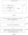
- the method includes: receiving a light beam from a photographed object, and transmitting the light beam to the light filtering layer; moving a position of the light filtering layer; and obtaining light signals filtered at different positions from the light filtering layer, and determining image information based on the light signals at the different positions.
- the position of the light filtering layer is moved, so that light signals filtered by the light filtering layer at different spatial positions are obtained, to complete sampling at different physical spatial positions, thereby increasing a sampling frequency at a spatial position, and helping improve a resolution of an image of the photographed object.
- the light filtering layer includes M light filtering units
- the camera module further includes N photosensitive units
- one light filtering unit allows light signals within at least one wavelength range to be filtered
- one photosensitive unit corresponds to at least three different light filtering units
- both N and M are integers greater than 2.
- Positions of the light filtering units may be moved, so that each light filtering unit corresponds to different photosensitive units. Light signals respectively filtered by at least three corresponding different light filtering units are obtained, to obtain P light signals, and image information is determined based on the P light signals.
- P is an integer greater than 2, and wavelength ranges of at least three of the P light signals are different.
- the positions of the light filtering units are moved, so that each light filtering unit corresponds to different photosensitive units, and one photosensitive unit may obtain P real light signals transmitted by at least three corresponding light filtering units. Wavelength ranges of at least three of the P light signals are different. Image information is determined based on the P light signals without a color guessing process, thereby helping improve accuracy of light beam collection performed by the photosensitive unit on the photographed object, and helping avoid a false color caused by color guessing. Further, if the at least three different light signals include a red light signal, a green light signal, and a blue light signal, a full color from the photographed object can be obtained.
- the light filtering unit may include a light filter. If an arrangement manner of light filters in the at least three different light filtering units is RGGB, RYYB, RGBW, RYBW, RGBWW-(NIR), or RYBWW-(NIR), switching is performed between the different photosensitive units in a plane parallel to the N photosensitive units and respectively along a row direction and a column direction of the array. If the arrangement manner of the light filters in the at least three different light filtering units is RGB or RYB, switching is performed between the different photosensitive units in a plane parallel to the N photosensitive units and along a column direction or a row direction of the array.
- RGGB, RYYB, RGBW, and RYBW are all 2*2 arrays, RGBWW-(NIR) and RYBWW-(NIR) are both 3*2 arrays or 2*3 arrays, and RGB and RYB are both 1*3 arrays or 3*1 arrays.
- the light filtering layer includes M light filtering units, and M is an integer greater than 2.
- the light filtering units may be moved between the K regions, to obtain light signals at K different spatial positions in the K regions, where K is an integer greater than 1.
- Image information is determined based on the light signals at the K different spatial positions.
- the light filtering units move between the K regions, so that light signals at K different spatial positions may be obtained, thereby increasing a frequency in light signal sampling at a spatial position, and helping improve a resolution of a formed image of the photographed object.
- the camera module may further include N photosensitive units.
- the light filtering units may move between the K regions along a plane parallel to the N photosensitive units, where a movement distance between two adjacent regions is less than a distance between geometric centers of two adjacent photosensitive units, and N is an integer greater than 2.
- this application provides a method for determining image information.
- the method may be applied to a camera module, the camera module includes M first lenses, and M is an integer greater than 2.
- the method includes: receiving a light beam from a photographed object, and transmitting the light beam to the M first lenses; converging the light beam, and moving the M first lenses between K regions; obtaining light signals at K different spatial positions in the K regions; and determining image information based on the light signals at the K different spatial positions, where K is an integer greater than 1.
- the first lenses move between the K regions, so that light signals at K different spatial positions may be obtained, thereby increasing a frequency in light signal sampling at a spatial position, and helping improve a resolution of a formed image of the photographed object.
- the camera module may further include N photosensitive units, and N is an integer greater than 2. Movement may be performed between the K regions along a plane parallel to the N photosensitive units, where a movement distance between two adjacent regions is less than a distance between geometric centers of two adjacent photosensitive units.
- this application provides a computer-readable storage medium.
- the computer-readable storage medium stores a computer program or instructions.
- the terminal device is enabled to perform the method in any one of the fifth aspect or the possible implementations of the fifth aspect, or the terminal device is enabled to perform the method in any one of the sixth aspect or the possible implementations of the sixth aspect.
- this application provides a computer program product.
- the computer program product includes a computer program or instructions.
- the terminal device is enabled to perform the method in any one of the fifth aspect or the possible implementations of the fifth aspect, or the terminal device is enabled to perform the method in any one of the sixth aspect or the possible implementations of the sixth aspect.
- this application provides a computer-readable storage medium.
- the computer-readable storage medium stores a computer program or instructions.
- the computer program or the instructions are executed by a camera, the camera is enabled to perform the method in any one of the fifth aspect or the possible implementations of the fifth aspect, or the camera is enabled to perform the method in any one of the sixth aspect or the possible implementations of the sixth aspect.
- this application provides a computer program product.
- the computer program product includes a computer program or instructions.
- the camera is enabled to perform the method in any one of the fifth aspect or the possible implementations of the fifth aspect, or the camera is enabled to perform the method in any one of the sixth aspect or the possible implementations of the sixth aspect.
- FIG. 1 a is a schematic diagram of a relationship between a pixel size and a resolution according to this application;
- FIG. 1 b is another schematic diagram of a relationship between a pixel size and a resolution according to this application;
- FIG. 2 a is a schematic diagram of a structure of a camera module according to this application.
- FIG. 2 b is a schematic diagram of a structure of another camera module according to this application.
- FIG. 3 a is a schematic diagram of a structure of a processing unit according to this application.
- FIG. 3 b is a schematic diagram of a structure of another light filtering unit according to this application.
- FIG. 3 c is a schematic diagram of a position relationship between a center of a light filter and a center of a first lens according to this application;
- FIG. 4 a is a schematic diagram of an arrangement manner of light filters in four light filtering units corresponding to one photosensitive unit according to this application;
- FIG. 4 b is a schematic diagram of another arrangement manner of light filters in four light filtering units corresponding to one photosensitive unit according to this application;
- FIG. 4 c is a schematic diagram of still another arrangement manner of light filters in four light filtering units corresponding to one photosensitive unit according to this application;
- FIG. 4 d is a schematic diagram of yet another arrangement manner of light filters in four light filtering units corresponding to one photosensitive unit according to this application;
- FIG. 4 e is a schematic diagram of an arrangement manner of light filters in six light filtering units corresponding to one photosensitive unit according to this application;
- FIG. 4 f is a schematic diagram of another arrangement manner of light filters in six light filtering units corresponding to one photosensitive unit according to this application;
- FIG. 4 g is a schematic diagram of an arrangement manner of light filters in three light filtering units corresponding to one photosensitive unit according to this application;
- FIG. 5 a is a schematic diagram of a structure of a light filtering layer according to this application.
- FIG. 5 b is a schematic diagram of a structure of another light filtering layer according to this application.
- FIG. 5 c is a schematic diagram of a structure of still another light filtering layer according to this application.
- FIG. 5 d is a schematic diagram of a structure of yet another light filtering layer according to this application.
- FIG. 5 e is a schematic diagram of a structure of still yet another light filtering layer according to this application.
- FIG. 5 f is a schematic diagram of a structure of a further light filtering layer according to this application.
- FIG. 5 g is a schematic diagram of a structure of a still further light filtering layer according to this application.
- FIG. 5 h is a schematic diagram of a structure of a yet further light filtering layer according to this application.
- FIG. 5 i is a schematic diagram of a structure of a light filtering layer according to this application.
- FIG. 6 is a schematic diagram of a relationship between a light filtering unit and a photosensitive unit according to this application;
- FIG. 7 is a schematic diagram of a process of moving a position of a light filtering unit to correspond to different photosensitive units according to this application;
- FIG. 8 is a schematic diagram of another process of moving a position of a light filtering unit to correspond to different photosensitive units according to this application;
- FIG. 9 is a schematic diagram of a structure of another camera module according to this application.
- FIG. 10 is a schematic diagram of a process of moving a first lens between K regions according to this application.
- FIG. 11 is a schematic diagram of a position relationship between a light filter and a photosensitive unit according to this application.
- FIG. 12 a is a schematic diagram of a position relationship between a first lens and a second lens according to this application;
- FIG. 12 b is a schematic diagram of another position relationship between a first lens and a second lens according to this application.
- FIG. 12 c is a schematic diagram of a position relationship and a light path between a first lens, a second lens, and a collimation lens according to this application;
- FIG. 13 is a schematic diagram of a structure of a terminal device according to an embodiment of this application.
- FIG. 14 is a schematic flowchart of a method for determining image information according to an embodiment of this application.
- FIG. 15 is a schematic flowchart of another method for determining image information according to an embodiment of this application.
- the resolution refers to a maximum quantity of pixels (photosensitive units) that are on an image sensor in a camera module and that can be used for imaging.
- the pixel refers to a minimum unit that constitutes an imaging region of the image sensor.
- a pixel size refers to a physical size of the pixel, that is, a distance between centers of adjacent pixels.
- the resolution is inversely proportional to the pixel size.
- FIG. 1 a and FIG. 1 b for a relationship between the pixel size and the resolution for a same photosensitive area.
- the pixel size is a, and the resolution is 4*4.
- the pixel size is a/2, and the resolution is 8*8. It can be determined from FIG. 1 a and FIG. 1 b that a smaller pixel size indicates a higher resolution, and a larger pixel size indicates a lower resolution.
- the high-resolution image looks clearer and sharper.
- the full color refers to a color constituted by three basic colors of red, green, and blue.
- a light beam from a photographed object passes through an optical lens component and is decomposed into monochromatic light signals by light filtering units in a light filtering layer.
- a light intensity value corresponding to each monochromatic light signal is recorded by a photosensitive unit in the image sensor to obtain unprocessed image data, and image information can be determined based on the unprocessed image data.
- a photosensitive unit of an image sensor can receive only a light signal in one fixed color (for example, one of red, yellow, green, and blue), while light in other colors needs to be determined by using a color guessing algorithm. Therefore, a resolution of an image formed by using a camera module in a conventional technology is relatively low.
- this application proposes a camera module.
- a light filtering layer that is, each light filtering unit in the light filtering layer
- a drive module to switch between different photosensitive units, so that each photosensitive unit can receive light signals transmitted from different light filtering units, and the photosensitive unit does not need to determine different light signals by using the color guessing algorithm, thereby helping improve a resolution of an image formed by using the camera module.
- the camera module proposed in this application is specifically described below with reference to FIG. 2 a to FIG. 12 c.
- FIG. 2 a is a schematic diagram of a structure of a camera module according to this application.
- the camera module may include an optical lens component, a light filtering layer, an image sensor, and a drive module.
- the optical lens component is configured to receive a light beam from a photographed object, and transmit the light beam to the light filtering layer.
- the light filtering layer is configured to move a position under the drive of the drive module, and respectively transmit light signals filtered at different positions to the image sensor.
- the image sensor is configured to receive the light signals at the different positions that are transmitted from the light filtering layer, and determine image information based on the light signals at the different positions.
- the drive module drives the light filtering layer to move the position, so that light signals filtered at different spatial positions may be respectively transmitted to the image sensor, and the image sensor may complete sampling at different physical spatial positions, thereby increasing a frequency of the image sensor in sampling at a spatial position, and helping improve a resolution of an image of the photographed object.
- the following further describes the camera module shown in FIG. 2 a , to provide an example of a specific implementation solution.
- FIG. 2 b is a schematic diagram of a structure of another camera module according to this application.
- the camera module may include an optical lens component, a light filtering layer, an image sensor, and a drive module.
- the light filtering layer includes M light filtering units, one light filtering unit allows light signals within at least one wavelength range to be filtered (which may also be referred to as pass), the image sensor includes N photosensitive units, and both M and N are integers greater than 2.
- one photosensitive unit corresponds to at least three different light filtering units.
- the optical lens component is configured to receive a light beam from a photographed object, and transmit the light beam to the light filtering layer.
- the light filtering unit is configured to move a position under the drive of the drive module to correspond to different photosensitive units, and respectively transmit filtered light signals to the different photosensitive units.
- the photosensitive unit is configured to: receive light signals respectively transmitted from the at least three corresponding different light filtering units, to obtain P light signals, and determine image information based on the P light signals, where P is an integer greater than 2, and wavelength ranges of at least three of the P light signals are different.
- the light filtering unit may be a minimum unit in the light filtering layer, and may selectively allow a wavelength range of an input light beam to pass. For example, in the input light beam, a light signal within a red light wavelength range is allowed to pass, and/or a light signal within a green light wavelength range is allowed to pass, and/or a light signal within a blue light wavelength range is allowed to pass.
- At least three different light filtering units corresponding to a photosensitive unit A include a light filtering unit a, a light filtering unit b, and a light filtering unit c.
- the light filtering unit a allows a light signal a to be filtered
- the light filtering unit b allows a light signal b to be filtered
- the light filtering unit c allows a light signal c to be filtered
- a wavelength range of the light signal a, a wavelength range of the light signal b, and a wavelength range of the light signal c are different from each other.
- the light filtering unit a, the light filtering unit b, and the light filtering unit c all move under the drive of the drive module to correspond to the photosensitive unit A.
- the photosensitive unit A may obtain the light signal a filtered by the light filtering unit a, the light signal b filtered by the light filtering unit b, and the light signal c filtered by the light filtering unit c. That is, the photosensitive unit A may obtain three light signals, and wavelength ranges corresponding to the three light signals are different from each other. If the wavelength ranges corresponding to the three light signals are respectively a red light wavelength range, a green light wavelength range, and a blue light wavelength range, the photosensitive unit A may collect a full color of the light beam from the photographed object.
- the drive module drives the light filtering unit to move the position to correspond to different photosensitive units, so that one photosensitive unit may receive P real light signals transmitted from at least three corresponding light filtering units.
- Wavelength ranges of at least three of the P light signals are different.
- the photosensitive unit may obtain at least three real light signals within different wavelength ranges.
- Image information is determined based on the P light signals without a color guessing process, thereby helping improve accuracy of light beam collection performed by the photosensitive unit on the photographed object, and helping avoid a false color caused by color guessing.
- the at least three different light signals include a red light signal, a green light signal, and a blue light signal, the photosensitive unit may collect a full color from the photographed object.
- one photosensitive unit corresponds to one light filtering unit.
- the light filtering unit is configured to move between K regions under the drive of the drive module, and transmit light signals at K different spatial positions that are obtained in the K regions to the corresponding photosensitive unit, where K is an integer greater than 1.
- the photosensitive unit is configured to receive the light signals at the K different spatial positions from the corresponding light filtering unit, and determine image information based on the light signals at the K different spatial positions.
- the drive module drives the light filtering unit to move between the K regions, so that one photosensitive unit may receive light signals at K different spatial positions from a corresponding light filtering unit, thereby increasing a frequency of the photosensitive unit in light signal sampling at a spatial position, and helping improve a resolution of a formed image.
- the camera module may complete sampling at different physical spatial positions by using a same photosensitive unit, thereby increasing a sampling frequency at a spatial position, and helping improve a resolution of an image of the photographed object.
- the K regions are K different spatial regions, and intensity of light signals corresponding to the K different spatial regions may be different.
- a light signal filtered by a light filtering unit is always input into a photosensitive unit corresponding to the light filtering unit.
- FIG. 2 a and FIG. 2 b The following describes each functional module and structure shown in FIG. 2 a and FIG. 2 b , to provide an example of a specific implementation.
- the optical lens component may include at least one optical lens, and may be configured to receive the light beam from the photographed object, and change a transmission direction of the light beam from the photographed object, so that the light beam is input into the light filtering layer as much as possible. Further, a focal length may be changed under the drive of a focus motor, so that the image sensor forms a clear image.
- FIG. 3 a is a schematic diagram of a structure of a light filtering layer according to this application.
- the light filtering unit includes a light filter and a first lens, and the first lens may be located on a surface that is of the light filter and that is opposite to the optical lens component.
- the first lens is configured to converge the light beam from the optical lens component, and transmit a converged light beam to the light filter.
- the light filter is configured to filter the converged light beam, and respectively transmit filtered light signals to different photosensitive units.
- the first lens is disposed above the light filter, and the first lens may collect and shape the light beam from the photographed object.
- FIG. 3 b is a schematic diagram of a structure of another light filtering unit according to this application.
- the light filtering unit may include a first lens, a light filter, and a second lens.
- the first lens may be located on a surface that is of the light filter and that is opposite to the optical lens component
- the second lens is located on a surface that is of the light filter and that is opposite to the image sensor.
- the first lens and the second lens are located on opposite surfaces of the light filter.
- the first lens is configured to converge the light beam from the optical lens component, and transmit a converged light beam to the light filter.
- the light filter is configured to filter the converged light beam, and transmit filtered light signals to the second lens.
- the second lens is configured to receive the light signals from the light filter, converge the light signals, and respectively transmit converged light signals to different photosensitive units.
- the second lens is disposed so that on one hand, the light signals filtered by the light filter can be further converged, and on the other hand, a distance between the light filter and the photosensitive unit can be increased, thereby helping reduce packaging difficulty of the camera module.
- FIG. 3 c is a schematic diagram of a position relationship between a center of a light filter and a center of a first lens according to this application. If the light filtering unit is located at a central position of the light filtering layer, the center of the first lens is aligned with the center of the light filter. If the light filtering unit is located in a region of the light filtering layer other than the central position, a first distance between the center of the light filtering layer and a center of the light filtering layer is greater than a second distance between the center of the first lens and the center of the light filtering layer.
- the center of the first lens is closer to the center of the light filtering layer than the center of the light filtering layer. This helps prevent one light filter from transmitting a filtered light signal to two photosensitive units at a time when the light beam from the photographed object is input at a relatively large angle, to avoid a “cross-color” problem.
- a difference between a first distance corresponding to a light filtering unit at a first position and a corresponding second distance is less than a difference between a first distance corresponding to a light filtering unit at a second position and a corresponding second distance.
- a distance between the first position and the center of the light filtering layer is less than a distance between the second position and the center of the light filtering layer.
- the first distance is a distance between a center of the light filtering layer and the center of the light filtering layer.
- the second distance is a distance between a center of a first lens and the center of the light filtering layer.
- a distance between the center of the light filter and the center of the first lens is larger, which may be of a stepped type.
- the center of the light filter is farther from the center of the light filtering layer than the center of the first lens.
- the light filters may have a geometrically symmetrical shape (for example, a square or regular hexagonal shape), the light filters may be closely arranged into an array, and an effective array region in the array may be rectangular or square as a whole, that is, the light filtering layer may be square or rectangular. It may be understood that when the light filters are square, the light filtering layer formed by closely arranging the light filters may be square or rectangular. When the light filters are in the regular hexagonal shape, the light filtering layer formed by closely arranging the light filters may be approximately rectangular or square as a whole, and has an uneven edge.
- a geometrically symmetrical shape for example, a square or regular hexagonal shape
- the center of the light filtering layer may be an intersection between diagonal lines of a rectangular or square effective region.
- the center of the light filter refers to a geometric center of the light filter
- the center of the first lens refers to a geometric center of the first lens.
- the center of the light filter is an intersection between diagonal lines.
- the first lens is spherical or ellipsoidal, the center of the first lens is also an intersection between diagonal lines.
- a center of the second lens is aligned with the center of the light filter.
- the camera module may further include M collimation lenses, and one collimation lens corresponds to one first lens.
- the collimation lens may be located between the first lens and a photosensitive unit, and the collimation lens is configured to collimate a converged light signal from the first lens, and transmit collimated light to a corresponding photosensitive unit.
- the collimation lens may be located between the first lens and the optical lens component, and the collimation lens is configured to collimate the light beam from the optical lens component, and transmit collimated light to the first lens. With the collimation lens, an output light signal can be closer to parallel light.
- the camera module may include a light filter, a first lens, and a collimation lens.
- the camera module may include a light filter, a first lens, a second lens, and a collimation lens.
- an arrangement manner of light filters in at least three different light filtering units corresponding to one photosensitive unit may include any one of the following cases.
- FIG. 4 a is a schematic diagram of an arrangement manner of light filters in four light filtering units corresponding to one photosensitive unit according to this application.
- the four light filters RGGB may form a 2*2 array.
- the R light filter is a light filter that allows a red light signal to be filtered.
- the G light filter is a light filter that allows a green light signal to be filtered.
- the B light filter is a light filter that allows a blue light signal to be filtered.
- one photosensitive unit may collect a full color, that is, a red light signal, a green light signal, and a blue light signal, from the photographed object without a color guessing process, thereby helping improve accuracy of light beam collection performed by the photosensitive unit on the photographed object.
- a structure of the light filtering layer may be shown in FIG. 5 a , and the light filters in the light filtering layer may be arranged by using RGGB shown in FIG. 4 a as a minimum repeatable unit.
- Two R light filters, two B light filters and four G light filters are distributed around each G light filter.
- a quantity of G light filters in the light filtering layer is twice a quantity of light filters for each of other two colors.
- FIG. 4 b is a schematic diagram of another arrangement manner of light filters in four light filtering units corresponding to one photosensitive unit according to this application.
- the four light filters RYYB may form a 2*2 array.
- the R light filter is a light filter that allows a red light signal to be filtered.
- the Y light filter is a light filter that allows a red light signal and a green light signal to be filtered.
- the B light filter is a light filter that allows a blue light signal to be filtered.
- one photosensitive unit may collect a full color, that is, a red light signal, a green light signal, and a blue light signal, from the photographed object without a color guessing process, thereby helping improve accuracy of light beam collection performed by the photosensitive unit on the photographed object.
- a structure of the light filtering layer may be shown in FIG. 5 b , and the light filters in the light filtering layer may be arranged by using RYYB shown in FIG. 4 b as a minimum repeatable unit.
- FIG. 4 c is a schematic diagram of still another arrangement manner of light filters in four light filtering units corresponding to one photosensitive unit according to this application.
- the four light filters RYBW may form a 2*2 array.
- R light filter, the Y light filter, and the B light filter refer to the description of the foregoing case 2. Details are not described herein again.
- the W light filter is a white light filter that allows all visible light to pass. With the W light filter, in a scenario with relatively low ambient luminance, an amount of light entering the image sensor in the camera module can be increased for synthesis into a low-light image of higher quality. It should be understood that, the case 3 may be understood as replacing a repeated Y light filter in the case 2 with a W light filter.
- a structure of the light filtering layer may be shown in FIG. 5 c , and the light filters in the light filtering layer may be arranged by using RYBW shown in FIG. 4 c as a minimum repeatable unit.
- FIG. 4 d is a schematic diagram of yet another arrangement manner of light filters in four light filtering units corresponding to one photosensitive unit according to this application.
- the four light filters RGBW may form a 2*2 array.
- the R light filter, the G filter, and the B light filter refer to the description of the foregoing case 1.
- the W light filter refer to the description of the foregoing case 3. Details are not described herein again. It should be understood that, the case 4 may be understood as replacing a G filter in the case 1 with a W light filter.
- a structure of the light filtering layer may be shown in FIG. 5 d , and the light filters in the light filtering layer may be arranged by using RGBW shown in FIG. 4 d as a minimum repeatable unit.
- the six light filters RGBWW-(NIR) may form a 3*2 array or a 2*3 array.
- FIG. 4 e is a schematic diagram of another arrangement manner of light filters in six light filtering units corresponding to one photosensitive unit according to this application. That the RGBWW-(NIR) light filters form a 3*2 array is used as an example for description.
- the R light filter, the G filter, and the B light filter refer to the description of the foregoing case 1.
- the W light filter refer to the description of the foregoing case 3. Details are not described herein again one by one.
- the W ⁇ light filter is a white light reduced filter (also referred to as a white light reduced lens), which allows 50% (or a lower percentage, such as 25%) of visible light to pass.
- the near-infrared (NIR) light filter is a light filter that allows a near-infrared light signal to pass.
- a structure of the light filtering layer may be shown in FIG. 5 e , and the light filters in the light filtering layer may be arranged by using RGBWW-(NIR) shown in FIG. 4 e as a minimum repeatable unit.
- the six light filters RYBWW-(NIR) may form a 3*2 array or a 2*3 array.
- FIG. 4 f is a schematic diagram of another arrangement manner of light filters in six light filtering units corresponding to one photosensitive unit according to this application. That the four light filters RYBWW-(NIR) form a 3*2 array is used as an example for description.
- the R light filter, the Y light filter, and the B light filter refer to the description of the foregoing case 2.
- For the W light filter refer to the description of the foregoing case 3.
- For the W ⁇ light filter and the NIR light filter refer to the description of the foregoing case 5. Details are not described herein again one by one.
- a structure of the light filtering layer may be shown in FIG. 5 f , and the light filters in the light filtering layer may be arranged by using RYBWW-(NIR) shown in FIG. 4 f as a minimum repeatable unit.
- a W light filter is disposed, so that in a scenario with relatively low ambient luminance, an amount of light entering the image sensor in the camera module can be increased.
- a W ⁇ light filter is disposed, so that based on a light attenuation characteristic of the W ⁇ light filter, an amount of light entering the image sensor in the camera module can be reduced in an extremely bright environment.
- a combination of the W light filter and the W ⁇ light filter can achieve dynamic range representation of a higher range in an environment with a high light ratio.
- a NIR light filter is disposed, so that a unique image in a NIR band can be obtained.
- the three light filters RGB may form a 1*3 array or a 3*1 array.
- FIG. 4 g is a schematic diagram of another arrangement manner of light filters in three light filtering units corresponding to one photosensitive unit according to this application. That the RGB light filters form a 1*3 array is used as an example.
- the R light filter, the G light filter, and the B light filter refer to the description of the foregoing case 1. Details are not described herein again.
- a structure of the light filtering layer may be shown in FIG. 5 g , and the light filters in the light filtering layer may be arranged by using RGB shown in FIG. 4 g as a minimum repeatable unit.
- a structure of the light filtering layer may alternatively be a combination of a 1*3 array formed by three RGB light filters and a 3*1 array formed by three RGB light filters, referring to a light filtering layer shown in FIG. 5 h.
- the case 8 may be understood as replacing the G light filter in the foregoing case 7 with a Y light filter.
- G light filter in the foregoing case 7
- Y light filter for a specific structure, refer to the description of the foregoing case 7. Details are not described herein again.
- the drive module may drive the light filtering layer to move the position in a direction perpendicular to a stripe formed by same light filters, so that one photosensitive unit may collect a full color, that is, a red light signal, a green light signal, and a blue light signal, from the photographed object without a color guessing process, thereby improving accuracy of light beam collection performed by the photosensitive unit on the photographed object, and helping reduce a time for image photographing by the camera module.
- the particular light filters allow particular light signals to pass.
- the particular light filters may allow light signals within a particular wavelength range to be filtered.
- the particular light filters are disposed in the light filtering layer, so that particular light signals can be detected.
- light filters that allow the light signals within the particular wavelength ranges to pass may be disposed in the light filtering layer.
- a light filter that allows the light signal of about 810 nm to pass may be disposed in the light filtering layer.
- the light signal of about 810 nm is a particular light signal
- the light filter that allows the light signal of about 810 nm to pass is a particular light filter.
- the preset rule may be arrangement at equal intervals.
- the particular light filters are uniformly distributed in the light filtering layer.
- the particular light filters are uniformly distributed in a region (for example, a central region, an edge region, or an intermediate transition region) of the light filtering layer.
- the preset rule may be that the light filtering layer is divided into at least two regions, arrangement is performed at equal intervals in each region, and intervals corresponding to the at least two regions are different.
- the light filtering layer may be divided into a central region, an edge region, and an intermediate transition region, the particular light filters are arranged at equal intervals in the central region, the edge region, and the intermediate transition region, but an interval corresponding to the central region, an interval corresponding to the edge region, and an interval corresponding to the intermediate transition region are unequal to each other.
- the preset rule may be that the light filtering layer is divided into at least two regions, arrangement is performed at equal intervals in each region, and intervals corresponding to the at least two regions are the same.
- the central region, the edge region, and the intermediate transition region may be rectangular, or may be circular. This is not limited in this application.
- FIG. 5 i is a schematic diagram of a structure of another light filtering layer according to this application.
- the light filtering layer is arranged by using RYYB shown in FIG. 4 b as a minimum repeatable unit, and particular light filters are disposed at equal intervals (one is disposed every three light filters along a row direction of the array, and one is disposed every two light filters along a column direction of the array).
- the light filtering layer is arranged by using RYYB as a minimum repeatable unit, and a light filter at a preset position in RYYB is replaced with a particular light filter.
- the arrangement manners of light filters in at least three different light filtering units corresponding to one photosensitive unit in the foregoing case 1 to case 9 are merely examples.
- light filters in at least three different light filtering units corresponding to one photosensitive unit may alternatively be arranged in any other possible arrangement manner.
- RGGB, RYYB, RGBW, and RYBW may all be a 1*4 array or a 4*1 array.
- RGBWW-(NIR) and RYBWW-(NIR) may both be a 1*6 array or a 6*1 array.
- RGB and RYB may be arranged with two in one row and one in another row.
- the arrangement manner of light filters in at least three different light filtering units is not limited in this application.
- the drive module may be configured to drive the light filtering unit to move a position, to correspond to different photosensitive units.
- the drive module may be configured to drive the light filtering unit to switch from one photosensitive unit to another photosensitive unit. In other words, the light filtering unit moves the position based on a photosensitive unit level.
- a shape of the light filter may be consistent with a shape of the photosensitive unit.
- a size of the light filter is greater than a size of the photosensitive unit, and a ratio of the size of the light filter to the size of the photosensitive unit ranges between 1 and 1.5 times.
- FIG. 6 is a schematic diagram of a relationship between a light filtering unit and a photosensitive unit according to this application.
- a size of a total effective region of the light filtering layer is also greater than a size of a corresponding effective region of the image sensor below the light filtering layer, whose ratio is consistent with or slightly greater than the ratio of the size of the light filter to the size of the photosensitive unit. This can help overcome impact of a process deviation during packaging of the light filtering layer and the image sensor. It should be noted that, to facilitate packaging of the camera module, generally, the quantity M of light filtering units is greater than the quantity N of photosensitive units, and both M and N are positive integers greater than 2.
- the drive module may be configured to drive the light filtering unit to switch between different photosensitive units in a plane parallel to the image sensor and respectively along a row direction and a column direction of the array.
- RGGB, RYYB, RGBW, and RYBW are all 2*2 arrays, and RGBWW-(NIR) and RYBWW-(NIR) are both 3*2 arrays or 2*3 arrays.
- the drive module is configured to drive the light filtering unit to switch between different photosensitive units in a plane parallel to the image sensor and along a column direction or a row direction of the array.
- RGB and RYB are both 1*3 arrays or 3*1 arrays.
- the plane parallel to the image sensor is a plane in which XOY are located, a row direction is a direction in which an X axis is located, and a column direction is a direction in which a Y axis is located.
- the R light filtering unit is referred to as R for short
- the G light filtering unit is referred to as G for short
- the B light filtering unit is referred to as B for short
- the Y light filtering unit is referred to as Y for short
- the W light filtering unit is referred to as W for short
- the W ⁇ light filtering unit is referred to as W ⁇ for short
- the NIR light filtering unit is referred to as NIR for short.
- each R may be replaced with the R light filtering unit
- each G may be replaced with the G light filtering unit
- each B may be replaced with the B light filtering unit
- each Y may be replaced with the Y light filtering unit
- each W may be replaced with the W filtering unit
- each NIR may be replaced with the NIR light filtering unit
- each W ⁇ may be replaced with the W ⁇ light filtering unit.
- FIG. 7 shows an example of a schematic diagram of a process of moving a position of a light filtering unit to correspond to different photosensitive units according to this application.
- FIG. 7 ( a ) shows an initial state for reference, in which one photosensitive unit corresponds to one light filtering unit below, and light filtering units R 22 , G 22 , G 22 , and B 22 marked by a circle correspond to four photosensitive units (a photosensitive unit a, a photosensitive unit b, a photosensitive unit c, and a photosensitive unit d) below.
- the drive module drives the light filtering layer to move by a distance of a side length of one photosensitive unit along a column direction (a positive direction of a Y axis) to obtain a correspondence shown in FIG. 7 ( b ) .
- the photosensitive unit a corresponds to G 22
- the photosensitive unit b corresponds to B 22
- the photosensitive unit c corresponds to R 32
- the photosensitive unit d corresponds to G 32 .
- the drive module then drives the light filtering layer to move by a distance of a side length of one photosensitive unit along a row direction (a negative direction of an X axis) to obtain a correspondence shown in FIG. 7 ( c ) .
- the photosensitive unit a corresponds to B 22
- the photosensitive unit b corresponds to G 23
- the photosensitive unit c corresponds to G 32
- the photosensitive unit d corresponds to R 33 .
- the drive module then drives the light filtering layer to move by a distance of a side length of one photosensitive unit along the column direction (the positive direction of the Y axis) to obtain a correspondence shown in FIG. 7 ( d ) .
- FIG. 7 ( d ) the correspondence shown in FIG.
- the photosensitive unit a corresponds to G 32
- the photosensitive unit b corresponds to R 33
- the photosensitive unit c corresponds to B 32
- the photosensitive unit d corresponds to G 33 .
- the photosensitive unit a respectively corresponds to R 22 , G 22 , B 22 , and G 32 , that is, the photosensitive unit a may receive a red light signal from R 22 , a green light signal from G 22 , a blue light signal from B 22 , and a green light signal from G 32 .
- the photosensitive unit b respectively corresponds to G 22 , B 22 , G 23 , and R 33 , that is, the photosensitive unit b may receive a green light signal from G 22 , a blue light signal from B 22 , a green light signal from G 32 , and a red light signal from R 33 .
- the photosensitive unit c respectively corresponds to G 22 , R 32 , G 32 , and B 32 , that is, the photosensitive unit c may respectively receive a green light signal from G 22 , a red light signal from R 32 , a green light signal from G 32 , and a blue light signal from B 32 .
- the photosensitive unit d respectively corresponds to B 22 , G 32 , R 33 , and G 33 , that is, the photosensitive unit d may respectively receive a blue light signal from B 22 , a green light signal from G 32 , a red light signal from R 33 , and a green light signal from G 33 .
- Each photosensitive unit in the circle may receive one red light signal, one blue light signal, and two green light signals.
- the directions in which the drive module drives the light filtering layer to move are merely examples, and movement may be performed in other directions to enable the light filtering unit to correspond to different photosensitive units.
- the photosensitive unit a in FIG. 7 ( a ) is used as an example.
- the photosensitive unit a corresponds to R 22 .
- the drive module may drive the light filtering layer to move by a distance of a side length of one photosensitive unit along the row direction (the negative direction of the X axis). In this case, the photosensitive unit a corresponds to G 22 .
- the drive module then drives the light filtering layer to move by a distance of a side length of one photosensitive unit along the column direction (the positive direction of the Y axis).
- the photosensitive unit a corresponds to B 22 .
- the drive module then drives the light filtering layer to move by a distance of a side length of one photosensitive unit along a row direction (a positive direction of the X axis).
- the photosensitive unit a corresponds to G 22 . That is, the photosensitive unit a respectively corresponds to R 22 , G 22 , B 22 and G 22 , and the photosensitive unit a may respectively receive a red light signal from R 22 , green light signals from two G 22 , and a blue light signal from B 22 .
- numbers for example, 22 , 23 , and 33 ) are merely used to indicate different positions.
- R 22 and R 23 are two same light filters, but are located at different positions.
- one photosensitive unit corresponds to three light filtering units, that is, one photosensitive unit corresponds to three light filters RGB.
- FIG. 8 shows an example of a schematic diagram of another process of moving a position of a light filtering unit to correspond to different photosensitive units according to this application.
- FIG. 8 ( a ) shows an initial state for reference, in which one photosensitive unit corresponds to one light filtering unit below, and light filtering units R 21 , G 21 , and B 21 marked by an ellipse correspond to three photosensitive units (a photosensitive unit 1 , a photosensitive unit 2 , and a photosensitive unit 3 ) below.
- the drive module drives the light filtering layer to move by a distance of a side length of one photosensitive unit along a column direction (a negative direction of a Y axis) to obtain a correspondence shown in FIG. 8 ( b ) .
- the photosensitive unit 1 corresponds to B 11
- the photosensitive unit 2 corresponds to R 21
- the photosensitive unit 3 corresponds to G 21 .
- the drive module then drives the light filtering layer to move by a distance of a side length of one photosensitive unit along the column direction (the negative direction of the Y axis) to obtain a correspondence shown in FIG. 8 ( c ) .
- FIG. 8 ( c ) In the correspondence shown in FIG.
- the photosensitive unit 1 corresponds to G 11
- the photosensitive unit 2 corresponds to B 11
- the photosensitive unit 3 corresponds to R 21 .
- the photosensitive unit 1 respectively corresponds to R 21 , B 11 , and G 11 , that is, the photosensitive unit 1 may receive a red light signal from R 21 , a green light signal from G 11 , and a blue light signal from B 11 .
- the photosensitive unit 2 respectively corresponds to G 21 , R 21 , and B 11 , that is, the photosensitive unit 2 may receive a green light signal from G 21 , a red light signal from R 21 , and a blue light signal from B 11 .
- the photosensitive unit 3 respectively corresponds to B 21 , G 21 , and R 21 , that is, the photosensitive unit 3 may respectively receive a blue light signal from B 21 , a green light signal from G 21 , and a red light signal from R 21 . That is, each marked photosensitive unit may receive one red light signal, one blue light signal, and one green light signal.
- the drive module may drive the light filtering layer to move in a column direction or a row direction. That is, the drive module may drive the light filtering layer to move in a direction of a single axis. With reference to FIG. 5 g , the drive module drives the light filtering layer to move the position in a direction perpendicular to a stripe formed by same light filters. In addition, full color sampling requires to collect only light signals filtered by three light filtering units, thereby helping reduce a time for image photographing by the camera module.
- the drive module may drive the light filtering unit to move between K regions along a plane parallel to the image sensor, where a movement distance between two adjacent regions is less than a distance between geometric centers of two adjacent photosensitive units.
- a movement distance between two adjacent regions is less than a distance between geometric centers of two adjacent photosensitive units.
- K is a square of an integer greater than 1.
- the light filtering unit may be configured to: under the drive of the drive module, move between the K regions along the plane parallel to the image sensor, where the movement distance between two adjacent regions is less than or equal to 1/ ⁇ K multiplied by the size of the photosensitive unit. Refer to the following description in FIG. 10 . A first lens in the description in FIG. 10 is replaced with a photosensitive unit. Details are not described herein one by one.
- the drive module may alternatively drive the light filtering layer to rotate by an angle on a plane perpendicular to the image sensor.
- rotation is performed by using a Z axis as a rotation axis, to correct a tilt deviation and a rotation deviation of the light filtering layer, so that an image with a better effect can be formed.
- a driving manner of the drive module includes, but is not limited to, electrostatic driving, voltage driving, thermoelectric driving, magnetoelectric driving, shape memory alloy (SMA) driving, motor driving, or the like.
- the drive module may be a micro-electro-mechanical system (MEMS) drive, a motor, or a servo motor.
- the drive module may drive, under the control of an electrical signal from a circuit board, the light filtering unit to switch from one photosensitive unit to another photosensitive unit.
- the photosensitive unit may be configured to: receive light signals respectively transmitted from at least three corresponding different light filtering units, to obtain P light signals, and perform optical-to-electrical conversion on the P light signals to obtain electrical signals, to form an image.
- one photosensitive unit corresponds to four light filtering units, that is, one photosensitive unit corresponds to four light filters RGGB.
- the photosensitive unit may receive light signals respectively transmitted from the four light filters RGGB.
- the R light filter may transmit a red light signal to the photosensitive unit
- each G light filter may transmit a green light signal to the photosensitive unit
- the B light filter may transmit a blue light signal to the photosensitive unit.
- the photosensitive unit may receive light signals respectively transmitted from the four corresponding light filters RGGB, that is, the photosensitive unit may receive one red light signal, two green light signals, and one blue light signal. In this way, the photosensitive unit may collect the full color from the photographed object, thereby helping improve accuracy of light beam collection performed by the photosensitive unit on the photographed object.
- one photosensitive unit corresponds to four light filtering units, that is, one photosensitive unit corresponds to four light filters RYYB.
- the photosensitive unit may receive light signals respectively transmitted from the four light filters RYYB.
- the R light filter may transmit a red light signal to the photosensitive unit
- each Y light filter may transmit a green light signal and a red light signal to the photosensitive unit
- the B light filter may transmit a blue light signal to the photosensitive unit.
- the photosensitive unit may receive light signals respectively transmitted from the four corresponding light filters RYYB, that is, the photosensitive unit may receive three red light signals, two green light signals, and one blue light signal. In this way, the photosensitive unit may also collect the full color from the photographed object, thereby improving accuracy of light beam collection performed by the photosensitive unit on the photographed object.
- one photosensitive unit corresponds to four light filtering units, that is, one photosensitive unit corresponds to four light filters RGBW.
- the photosensitive unit may receive light signals respectively transmitted from the four light filters RGBW.
- the R light filter may transmit a red light signal to the photosensitive unit
- the G light filter may transmit a green light signal to the photosensitive unit
- the B light filter may transmit a blue light signal to the photosensitive unit
- the W light filter may transmit a 100% white light signal to the photosensitive unit.
- the photosensitive unit may receive light signals respectively transmitted from the four corresponding light filters RGBW, that is, the photosensitive unit may receive one red light signal, one green light signal, one blue light signal, and one white light signal. In this way, the photosensitive unit may also collect the full color from the photographed object, thereby helping improve accuracy of light beam collection performed by the photosensitive unit on the photographed object.
- an amount of light entering the image sensor can be increased.
- one photosensitive unit may receive two red light signals, one green light signal, one blue light signal, and one 100% white light signal.
- one photosensitive unit may receive one red light signal, one green light signal, one blue light signal, one 100% white light signal, one white light signal (25%) reduced white light signal, and one near-infrared light signal.
- the photosensitive unit may also collect the full color from the photographed object, thereby helping improve accuracy of light beam collection performed by the photosensitive unit on the photographed object.
- an amount of light entering the image sensor can be reduced.
- a unique image in a NIR band can be obtained.
- one photosensitive unit may receive two red light signals, one green light signal, one blue light signal, one 100% white light signal, one white light (25%) reduced white light signal, and one near-infrared light signal.
- one photosensitive unit may receive one red light signal, one green light signal, and one blue light signal. In this way, the photosensitive unit may also collect the full color from the photographed object, thereby helping improve accuracy of light beam collection performed by the photosensitive unit on the photographed object.
- one photosensitive unit may receive two red light signals, one green light signal, and one blue light signal. In this way, the photosensitive unit may also collect the full color from the photographed object, thereby helping improve accuracy of light beam collection performed by the photosensitive unit on the photographed object.
- the photosensitive unit may further receive a particular light signal filtered by the particular light filter, and may output intensity of the particular light signal, so that the particular light signal can be detected.
- the photosensitive unit may include one or more pixels.
- one light filtering unit corresponds to one pixel.
- one light filtering unit corresponds to a plurality of pixels, each pixel may collect a light signal transmitted by the light filtering unit, and the plurality of pixels may output one or more results.
- a same light signal may be detected by using a plurality of pixels, so that a signal-to-noise ratio of a detected light signal can be effectively improved.
- the photosensitive unit may be a photodetector (PD), a high-speed photodiode, a charge coupled device (CCD), or a complementary metal-oxide-semiconductor (CMOS) phototransistor.
- the image sensor converts a light signal into an electrical signal, and then transmits the electrical signal to an ISP to convert the electrical signal into a digital image signal.
- the image sensor may be a black-and-white image sensor.
- the black-and-white image sensor is currently relatively mature, and the camera module may directly use an existing mature black-and-white image sensor, so that costs of the camera module can be reduced.
- FIG. 9 is a schematic diagram of a structure of another camera module according to this application.
- the camera module may include an optical lens component, M first lenses, M light filters, an image sensor, and a drive module.
- One light filter allows light signals within at least one wavelength range to be filtered
- the image sensor includes N photosensitive units, one first lens corresponds to one photosensitive unit, one photosensitive unit corresponds to one light filter, and both N and M are integers greater than 2.
- the optical lens component is configured to receive a light beam from a photographed object, and transmit the light beam to the M first lenses.
- the first lens is configured to converge the light beam from the optical lens component, move between K regions under the drive of the drive module, and transmit light signals at K different spatial positions that are obtained in the K regions to the corresponding light filter, where K is an integer greater than 1.
- the light filter is configured to filter the light signals from the corresponding first lens, and transmit filtered light signals to the corresponding photosensitive unit.
- the photosensitive unit is configured to receive the light signals at the K different spatial positions from the corresponding light filter, and determine image information based on the light signals at the K different spatial positions.
- the first lens moves between the K regions under the drive of the drive module, so that one photosensitive unit may receive light signals at K different spatial positions from a corresponding light filter, thereby increasing a frequency of the photosensitive unit in light signal sampling at a spatial position, and helping improve a resolution of an image of the photographed object.
- the camera module may complete sampling at different physical spatial positions by using a same photosensitive unit, thereby increasing a sampling frequency at a spatial position.
- the K regions are K different spatial regions, and intensity of light signals corresponding to the K different spatial regions may be different.
- the light filter may allow a light signal within at least one wavelength range in the light signals to be filtered.
- a light signal filtered by a light filter is always input into a photosensitive unit corresponding to the light filter.
- the first lens is configured to: under the drive of the drive module, move between the K regions along a plane parallel to the image sensor, where a movement distance between two adjacent regions is less than a distance between geometric centers of two adjacent photosensitive units.
- K is a square of an integer greater than 1.
- the first lens may be configured to: under the drive of the drive module, move between the K regions along the plane parallel to the image sensor, where the movement distance between two adjacent regions is less than or equal to 1/ ⁇ K multiplied by a size of a photosensitive unit.
- the photosensitive unit is square.
- a side length is L
- a space corresponding to one photosensitive unit is divided into four regions
- a size of the photosensitive unit is the side length L of the photosensitive unit.
- FIG. 10 is described by using an example in which the distance by which the drive module drives the first lens to move is L/2.
- the light filter is fixed to the first lens.
- the drive module may drive the first lens and the light filter together to move between the K regions. Based on the structure 1, for a position relationship between the first lens and the light filter, refer to the descriptions in FIG. 3 a and FIG. 3 c . Details are not described herein again.
- the camera module further includes M second lenses, and one second lens corresponds to one light filter.
- one second lens corresponds to one light filter.
- a center of the second lens is aligned with the center of the light filter.
- the structure 1 may be consistent with the structure of the camera module shown in FIG. 2 b and the optional implementation, except as follows: Based on the structure 1, the drive module drives the light filter and the first lens together to move between the K regions, and the obtained light signals at the K spatial positions are transmitted to one photosensitive unit. In FIG. 2 b and the optional implementation, the drive module drives the light filtering unit to move the position, to correspond to different photosensitive units, and the light filtering unit respectively transmits the filtered light signals to the different photosensitive units.
- the image sensor may be a black-and-white image sensor.
- An existing black-and-white image sensor that is relatively mature may be used, so that costs of the camera module can be reduced.
- the light filter and the photosensitive unit are disposed together.
- the drive module drives the first lens to move between the K regions, the light filter remains stationary.
- FIG. 11 is a schematic diagram of a position relationship between a light filter and a photosensitive unit according to this application.
- the light filter is located on a surface that is of the photosensitive unit and that is opposite to the optical lens component.
- FIG. 11 is described by using the four light filters RGGB in the foregoing case 1 are used as an example.
- One light filter is located on a surface that is of one photosensitive unit and that is opposite to the optical lens component.
- a size of the light filter may be consistent with a size of the photosensitive unit.
- the camera module may further include M second lenses, and one second lens corresponds to one first lens.
- FIG. 12 a is a schematic diagram of a position relationship between a first lens and a second lens according to this application.
- the second lens is located on a surface that is of the first lens and that is opposite to the image sensor.
- the second lens is configured to receive converged light from the corresponding first lens, further converge the converged light, and transmit further converged light to a corresponding light filter.
- FIG. 12 b is a schematic diagram of another position relationship between a first lens and a second lens according to this application.
- a transparent substrate is disposed between the first lens and the second lens.
- the first lens and the second lens are located on two opposite surfaces of the transparent substrate.
- the transparent substrate may be glass.
- the camera module may further include M collimation lenses, and one collimation lens corresponds to one first lens.
- FIG. 12 c is a schematic diagram of a position relationship and a light path between a first lens, a second lens, and a collimation lens according to this application.
- the collimation lens is located between the first lens and a photosensitive unit, and the collimation lens is configured to collimate converged light from the first lens, and transmit collimated light to a corresponding photosensitive unit. With the collimation lens, an output light signal can be closer to parallel light.
- the collimation lens shown in FIG. 12 c may alternatively be located between the first lens and the optical lens component, and the collimation lens is configured to collimate the light beam from the optical lens component, and transmit collimated light to the corresponding first lens.
- a collimated and converged light beam may be formed, and the collimated and converged light beam is transmitted to a corresponding light filter.
- the camera module in this application may alternatively include more lenses, to converge and collimate the light beam from the photographed object. A quantity of lenses is not limited in this application.
- the M light filters may be repeatedly arranged in any one of the following manners.
- a W light filter is disposed, so that in a scenario with relatively low ambient luminance, an amount of light entering the image sensor in the camera module can be increased.
- a W ⁇ light filter is disposed, so that based on a light attenuation characteristic of the W ⁇ light filter, an amount of light entering the image sensor in the camera module can be reduced in an extremely bright environment.
- a combination of the W light filter and the W ⁇ light filter can achieve dynamic range representation of a higher range in an environment with a high light ratio.
- a NIR light filter is disposed, so that a unique image in a NIR band can be obtained.
- the preset rule includes arrangement at equal intervals; or the preset rule includes that the light filtering layer is divided into at least two regions, arrangement is performed at equal intervals in each region, and intervals corresponding to the at least two regions are different or the same.
- an arrangement manner of the light filters may be any manner in the foregoing case 1 to case 9.
- an arrangement manner of the light filters may be any manner in the foregoing case 1 to case 9.
- M is generally an integer equal to N.
- the image sensor may be a black-and-white image sensor or a color image sensor.
- the color image sensor is a combination of the light filter and the photosensitive unit in the structure 2.
- the camera module may further include a light bandpass filter (refer to FIG. 2 b or FIG. 9 ).
- the light bandpass filter is a piece of planar glass or a glass-like resin material, which blocks or absorbs light of a particular wavelength through surface coating or material doping, and transmits light of a specified wavelength, to implement a function of selectively allowing light of different wavelengths to pass.
- this application may further provide a camera.
- the camera may include the camera module and a fixing structure, and the fixing structure is configured to fix the camera module.
- the fixing structure is configured to fix the camera module.
- other components such as a processor or a memory may be further included.
- any camera having a photographing function may use the camera module provided in this application.
- this application may further provide a terminal device.
- the terminal device may include the camera module and a processor, and the processor may be configured to process image information in the camera module.
- the processor may be configured to process image information in the camera module.
- other components such as a memory, a wireless communications apparatus, a sensor, a touchscreen, and a display may be further included.
- the terminal device may be a portable device, for example, a mobile phone, a tablet computer, a wearable device (for example, a smartwatch), or a camera (such as a mirrorless camera).
- a portable terminal device includes but is not limited to a portable terminal device using iOS®, Android®, Microsoft®, or another operating system.
- FIG. 13 is a schematic diagram of a structure of a terminal device according to an embodiment of this application.
- the terminal device 100 may include a processor 110 , a memory 111 , a camera module 112 , a display 113 , and the like. It should be understood that the hardware structure shown in FIG. 13 is merely an example.
- the terminal device to which this application is applicable may have more or fewer components than the terminal device 100 shown in FIG. 13 , may combine two or more components, or may have different component configurations. Components shown in the figure may be implemented in hardware, software, or a combination of hardware and software that includes one or more signal processing and/or application-specific integrated circuits.
- the processor 110 may include one or more processing units.
- the processor 110 may include an application processor (AP), a graphics processing unit (GPU), an image signal processor (ISP), a controller, and a digital signal processor (DSP).
- AP application processor
- GPU graphics processing unit
- ISP image signal processor
- DSP digital signal processor
- Different processing units may be independent components, or may be integrated into one or more processors.
- the camera module 112 may be configured to capture dynamic and static images and the like.
- the terminal device 100 may include one or Q camera modules 112 , and Q is a positive integer greater than or equal to 1.
- the terminal device 100 may include two camera modules 112 , one camera module 112 is a front-facing camera module, and the other camera module 112 is a rear-facing camera module.
- the terminal device 100 may alternatively include three camera modules 112 , one camera module 112 is a front-facing camera module, and the other two camera modules 112 are rear-facing camera modules.
- one camera module 112 is a rear-facing camera module, and the other two camera modules 112 are front-facing camera modules.
- the terminal device 100 includes four camera modules 112 , one camera module 112 is a front-facing camera module, and the other three camera modules 112 are rear-facing camera modules.
- the display 113 may be configured to display an image, a video, and the like.
- the display 113 may include a display panel.
- the display panel may be a liquid crystal display (LCD), an organic light-emitting diode (OLED), an active-matrix organic light emitting diode (AMOLED), a flexible light-emitting diode (FLED), Miniled, MicroLed, Micro-oLed, a quantum dot light emitting diode (QLED), or the like.
- the terminal device 100 may include one or H displays 113 , where H is a positive integer greater than 1.
- the terminal device 100 may implement a display function by using the GPU, the display 113 , the application processor, and the like.
- this application provides a method for determining image information, referring to a description in FIG. 14 .
- the method for determining image information may be applied to the camera module in any one of the embodiments shown in FIG. 2 b .
- the camera module includes a light filtering layer.
- the method includes the following steps.
- This step may be that the optical lens component transmits the light beam from the photographed object to the light filtering units.
- the optical lens component transmits the light beam from the photographed object to the light filtering units.
- This step gives example descriptions of the following two implementations of moving the light filtering layer.
- the light filtering layer includes M light filtering units
- the camera module further includes N photosensitive units
- one light filtering unit allows light signals within at least one wavelength range to be filtered
- one photosensitive unit corresponds to at least three different light filtering units
- both N and M are integers greater than 2. Positions of the light filtering units may be moved, so that each light filtering unit corresponds to different photosensitive units.
- the light filtering unit may include a light filter. If an arrangement manner of light filters in at least three different light filtering units corresponding to one photosensitive unit is RGGB, RYYB, RGBW, RYBW, RGBWW-(NIR), or RYBWW-(NIR), switching is performed between different photosensitive units in a plane parallel to the N photosensitive units and respectively along a row direction and a column direction of the array.
- RGGB, RYYB, RGBW, and RYBW are all 2*2 arrays, and RGBWW-(NIR) and RYBWW-(NIR) are both 3*2 arrays or 2*3 arrays.
- RGB and RYB are both 1*3 arrays or 3*1 arrays.
- the light filtering layer includes M light filtering units, and M is an integer greater than 2.
- the light filtering units may be moved between the K regions, to obtain light signals at K different spatial positions in the K regions, where K is an integer greater than 1.
- the camera module may further include N photosensitive units, and N is an integer greater than 2. Movement may be performed between the K regions along a plane parallel to the N photosensitive units, where a movement distance between two adjacent regions is less than a distance between geometric centers of two adjacent photosensitive units.
- the light signals respectively filtered by the at least three corresponding different light filtering units may be obtained, to obtain P light signals, and image information is determined based on the P light signals.
- P is an integer greater than 2, and wavelength ranges of at least three of the P light signals are different.
- the positions of the light filtering units are moved, so that each light filtering unit corresponds to different photosensitive units, and P real light signals transmitted by at least three corresponding light filtering units may be obtained.
- Wavelength ranges of at least three of the P light signals are different.
- Image information is determined based on the P light signals without a color guessing process, thereby helping improve accuracy of light beam collection performed by the photosensitive unit on the photographed object, and helping avoid a false color caused by a color guessing algorithm.
- the at least three different light signals include a red light signal, a green light signal, and a blue light signal, a full color from the photographed object can be obtained.
- the light signals at the K different spatial positions may be obtained, and image information is determined based on the light signals at the K different spatial positions.
- the positions of the light filtering units are moved, so that light signals at K different spatial positions may be obtained, thereby increasing a frequency in light signal sampling at a spatial position, and helping further improve a resolution of a formed image of the photographed object.
- step 1403 the position of the light filtering layer is moved, so that light signals filtered by the light filtering layer at different spatial positions are obtained, to complete sampling at different physical spatial positions, thereby increasing a sampling frequency at a spatial position, and helping improve a resolution of an image of the photographed object.
- this application provides another method for determining image information, referring to a description in FIG. 15 .
- the method for determining image information may be applied to the camera module in any one of the embodiments shown in FIG. 9 .
- the camera module may include M first lenses, and M is an integer greater than 2.
- the method includes the following steps.
- This step may be that the optical lens component transmits the light beam from the photographed object to the M first lenses.
- the optical lens component transmits the light beam from the photographed object to the M first lenses.
- the camera module may further include N photosensitive units, and N is an integer greater than 2. Movement may be performed between the K regions along a plane parallel to the N photosensitive units, where a movement distance between two adjacent regions is less than a distance between geometric centers of two adjacent photosensitive units. For a specific process, refer to the description of moving the first lens between the K regions. Details are not described herein again one by one.
- intensity of the light signals at the K different spatial positions may be different.
- the description of the camera module based on FIG. 9 Details are not described herein again one by one.
- the light signals at the K different spatial positions may be converted into electrical signals, and image information is determined based on the electrical signals obtained after conversion.
- the first lenses move between the K regions, so that light signals at K different spatial positions may be obtained, thereby increasing a frequency in light signal sampling at a spatial position, and helping improve a resolution of a formed image of the photographed object.
- the computer-readable storage medium stores a computer program or instructions.
- the terminal device is enabled to perform the method in any possible implementation in any one of the foregoing embodiments.
- the computer program product includes a computer program or instructions.
- the method in any one of the foregoing embodiments may be implemented.
- the computer-readable storage medium stores a computer program or instructions.
- the computer program or the instructions are executed by a camera, the camera is enabled to perform the method in any possible implementation in any one of the foregoing embodiments.
- the computer program product includes a computer program or instructions.
- the computer program or the instructions are executed by a camera, the method in the possible implementation in any one of the foregoing embodiments is implemented.
- the camera module shown in FIG. 2 b is used as an example.
- the light filtering unit is configured to move a position under the drive of the drive module, to correspond to different photosensitive units. Further, when corresponding to each photosensitive unit, the light filtering unit may move between K regions under the drive of the drive module, and transmit all light signals at K different spatial positions that are obtained in the K regions to the corresponding photosensitive unit.
- the photosensitive unit is configured to receive the light signals at the K different spatial positions that are respectively transmitted from at least three corresponding different light filtering units, to obtain P*K light signals. That is, the photosensitive unit may obtain P*K real light signal within wavelength ranges without a color guessing process, thereby helping improve accuracy of light beam collection performed by the photosensitive unit on the photographed object.
- each photosensitive unit may receive light signals at K different spatial positions from a corresponding light filter, thereby increasing a frequency of the photosensitive unit in light signal sampling at a spatial position, and helping improve a resolution of an image of a photographed object.
- At least one means one or more, and “a plurality of” means two or more.
- And/or describes an association relationship between associated objects, and represents that three relationships may exist.
- a and/or B may represent the following cases: A exists alone, both A and B exist, and B exists alone, where A and B may be singular or plural.
- At least one of the following items (pieces)” or a similar expression thereof indicates any combination of these items, including a single item (piece) or any combination of a plurality of items (pieces).
- At least one (piece) of a, b, or c may represent: a, b, c, “a and b”, “a and c”, “b and c”, or “a, b, and c”, where a, b, and c may be singular or plural.
- the character “/” usually indicates an “or” relationship between associated objects.
- this application may be provided as a method, a system, or a computer program product. Therefore, this application may use a form of hardware only embodiments, software only embodiments, or embodiments with a combination of software and hardware. In addition, this application may use a form of a computer program product that is implemented on one or more computer-usable storage media (including but not limited to a disk memory, a CD-ROM, an optical memory, and the like) that include computer-usable program code.
- a computer-usable storage media including but not limited to a disk memory, a CD-ROM, an optical memory, and the like
- These computer program instructions may be provided for a general-purpose computer, a dedicated computer, an embedded processor, or a processor of another programmable data processing device to generate a machine, so that the instructions executed by the computer or the processor of the another programmable data processing device generate an apparatus for implementing a specific function in one or more procedures in the flowcharts and/or in one or more blocks in the block diagrams.
- These computer program instructions may alternatively be stored in a computer-readable memory that can indicate a computer or another programmable data processing device to work in a specific manner, so that the instructions stored in the computer-readable memory generate an artifact that includes an instruction apparatus.
- the instruction apparatus implements a specific function in one or more procedures in the flowcharts and/or in one or more blocks in the block diagrams.
- These computer program instructions may alternatively be loaded onto the computer or the another programmable data processing device, so that a series of operations and steps are performed on the computer or the another programmable device, to generate computer-implemented processing. Therefore, the instructions executed on the computer or the another programmable device provide steps for implementing a specific function in one or more procedures in the flowcharts and/or in one or more blocks in the block diagrams.
Landscapes
- Engineering & Computer Science (AREA)
- Multimedia (AREA)
- Signal Processing (AREA)
- Physics & Mathematics (AREA)
- Spectroscopy & Molecular Physics (AREA)
- Blocking Light For Cameras (AREA)
- Studio Devices (AREA)
- Color Television Image Signal Generators (AREA)
Abstract
Description
-
- Case 1: One photosensitive unit corresponds to four light filtering units, light filters in the four light filtering units are RGGB, and RGGB form a 2*2 array.
- Case 2: One photosensitive unit corresponds to four light filtering units, light filters in the four light filtering units are RYYB, and RYYB form a 2*2 array.
-
- Case 3: One photosensitive unit corresponds to four light filtering units, light filters in the four light filtering units are RGB white (white, W), and RGBW form a 2*2 array.
- Case 4: One photosensitive unit corresponds to four light filtering units, light filters in the four light filtering units are RYBW, and RYBW form a 2*2 array.
-
- Case 5: One photosensitive unit corresponds to six light filtering units, light filters in the six light filtering units are RGBWW-(NIR), and RGBWW-(NIR) form a 3*2 array or a 2*3 array.
- Case 6: One photosensitive unit corresponds to six light filtering units, light filters in the six light filtering units are RYBWW-near-infrared (NIR), and RYBWW-(NIR) form a 3*2 array or a 2*3 array.
-
- Case 7: One photosensitive unit corresponds to three light filtering units, light filters in the three light filtering units are RGB, and RGB form a 1*3 array or a 3*1 array.
- Case 8: One photosensitive unit corresponds to three light filtering units, light filters in the three light filtering units are RYB, and RYB form a 1*3 array or a 3*1 array.
-
- Case 9: Based on any one of the
foregoing case 1 to case 8, the light filtering layer may further include particular light filters disposed according to a preset rule, and the particular light filters allow particular light signals to be filtered.
- Case 9: Based on any one of the
-
- Manner 1: Four light filters are RGGB, and RGGB form a 2*2 array.
- Manner 2: Four light filters are RYYB, and RYYB form a 2*2 array.
- Manner 3: Four light filters are RGBW, and RGBW form a 2*2 array.
- Manner 4: Four light filters are RYBW, and RYBW form a 2*2 array.
-
- Manner 5: Six light filters are RGBWW-(NIR), and RGBWW-(NIR) form a 3*2 array or a 2*3 array.
- Manner 6: Six light filters are RYBWW-(NIR), and RYBWW-(NIR) form a 3*2 array or a 2*3 array.
-
- Manner 7: Three light filters are RGB, and RGB form a 1*3 array or a 3*1 array.
- Manner 8: Three light filters are RYB, and RYB form a 1*3 array or a 3*1 array.
- Manner 9: Based on any one of the foregoing
manner 1 to manner 8, some of the M light filters are particular light filters that allow particular light signals to be filtered, and the particular light filters are arranged in a light filtering layer according to a preset rule.
-
- Implementation 1: Positions of light filtering units are moved, so that each light filtering unit corresponds to different photosensitive units.
-
- Implementation 2: Light filtering units are moved between K regions.
-
- Case 1: One photosensitive unit corresponds to four light filtering units, and light filters in the four light filtering units are RGGB.
-
- Case 2: One photosensitive unit corresponds to four light filtering units, and light filters in the four light filtering units are RYYB.
-
- Case 3: One photosensitive unit corresponds to four light filtering units, and light filters in the four light filtering units are RYBW.
-
- Case 4: One photosensitive unit corresponds to four light filtering units, and light filters in the four light filtering units are RGBW.
-
- Case 5: One photosensitive unit corresponds to six light filtering units, and light filters in the six light filtering units are RGBWW-(NIR).
-
- Case 6: One photosensitive unit corresponds to six light filtering units, and light filters in the six light filtering units are RYBWW-(NIR).
-
- Case 7: One photosensitive unit corresponds to three light filtering units, and light filters in the three light filtering units are RGB.
-
- Case 8: One photosensitive unit corresponds to three light filtering units, and light filters in the three light filtering units are RYB.
-
- Case 9: Based on any one of the foregoing
case 1 to case 8, the light filtering layer may further include particular light filters disposed according to a preset rule.
- Case 9: Based on any one of the foregoing
-
- Structure 1: The light filter is located on a surface that is of the first lens and that is opposite to the image sensor.
-
- Structure 2: The light filter is located on a surface that is of the photosensitive unit and that is opposite to the optical lens component.
-
- Manner 1: Four light filters are RGGB, and RGGB form a 2*2 array. For details, refer to the description of the foregoing
case 1. - Manner 2: Four light filters are RYYB, and RYYB form a 2*2 array. For details, refer to the description of the foregoing
case 2. - Manner 3: Four light filters are RGBW, and RGBW form a 2*2 array. For details, refer to the description of the foregoing
case 3. - Manner 4: Four light filters are RYBW, and RYBW form a 2*2 array. For details, refer to the description of the foregoing
case 4.
- Manner 1: Four light filters are RGGB, and RGGB form a 2*2 array. For details, refer to the description of the foregoing
-
- Manner 5: Six light filters are RGBWW-(NIR), and RGBWW-(NIR) form a 3*2 array or a 2*3 array. For details, refer to the description of the foregoing case 5.
- Manner 6: Six light filters are RYBWW-(NIR), and RYBWW-(NIR) form a 3*2 array or a 2*3 array. For details, refer to the description of the foregoing case 6.
-
- Manner 7: Three light filters are RGB, and RGB form a 1*3 array or a 3*1 array. For details, refer to the description of the foregoing case 7.
- Manner 8: Three light filters are RYB, and RYB form a 1*3 array or a 3*1 array. For details, refer to the description of the foregoing case 8.
- Manner 9: Based on any one of the foregoing
manner 1 to manner 8, some of the M light filters are particular light filters that allow particular light signals to be filtered, and the particular light filters are arranged in a light filtering layer according to a preset rule. For details, refer to the description of the foregoing case 9. Details are not described herein again one by one.
-
- Step 1401: Receive a light beam from a photographed object, and transmit the light beam to the light filtering layer.
-
- Step 1402: Move a position of the light filtering layer.
-
- Implementation 1: Positions of M light filtering units are moved, so that each light filtering unit corresponds to different photosensitive units.
-
- Implementation 2: Light filtering units are moved between K regions.
-
- Step 1403: Obtain light signals filtered at different positions from the light filtering layer, and determine image information based on the light signals at the different positions.
-
- Step 1501: Receive a light beam from a photographed object, and transmit the light beam to the M first lenses.
-
- Step 1502: Converge the light beam, and move the M first lenses between K regions, where K is an integer greater than 1.
-
- Step 1503: Obtain light signals at K different spatial positions in the K regions.
-
- Step 1504: Determine image information based on the light signals at the K different spatial positions.
Claims (19)
Applications Claiming Priority (3)
| Application Number | Priority Date | Filing Date | Title |
|---|---|---|---|
| CN201911159781.8 | 2019-11-22 | ||
| CN201911159781.8A CN112839215B (en) | 2019-11-22 | 2019-11-22 | Camera module, camera, terminal device, image information determination method and storage medium |
| PCT/CN2020/114434 WO2021098349A1 (en) | 2019-11-22 | 2020-09-10 | Camera module, camera, terminal device and image information determination method |
Related Parent Applications (1)
| Application Number | Title | Priority Date | Filing Date |
|---|---|---|---|
| PCT/CN2020/114434 Continuation WO2021098349A1 (en) | 2019-11-22 | 2020-09-10 | Camera module, camera, terminal device and image information determination method |
Publications (2)
| Publication Number | Publication Date |
|---|---|
| US20220256128A1 US20220256128A1 (en) | 2022-08-11 |
| US12219273B2 true US12219273B2 (en) | 2025-02-04 |
Family
ID=75921753
Family Applications (1)
| Application Number | Title | Priority Date | Filing Date |
|---|---|---|---|
| US17/732,109 Active 2041-02-19 US12219273B2 (en) | 2019-11-22 | 2022-04-28 | Camera module, camera, terminal device, and method for determining image information |
Country Status (4)
| Country | Link |
|---|---|
| US (1) | US12219273B2 (en) |
| EP (1) | EP4040785B1 (en) |
| CN (1) | CN112839215B (en) |
| WO (1) | WO2021098349A1 (en) |
Families Citing this family (7)
| Publication number | Priority date | Publication date | Assignee | Title |
|---|---|---|---|---|
| CN114650376B (en) * | 2022-03-02 | 2024-12-20 | 维沃移动通信有限公司 | Image sensor and electronic device |
| CN114755738B (en) * | 2022-04-18 | 2025-06-06 | 山东大学 | A carbon fiber cloth automatic deviation detection and correction device and control method thereof |
| CN115278000B (en) * | 2022-06-24 | 2025-01-24 | 维沃移动通信有限公司 | Image sensor, image generation method, camera module and electronic device |
| CN115118856B (en) * | 2022-06-24 | 2024-06-25 | 维沃移动通信有限公司 | Image sensor, image processing method, camera module and electronic equipment |
| CN117560563A (en) * | 2022-08-01 | 2024-02-13 | 华为技术有限公司 | Multispectral modules and electronic equipment |
| CN115361532B (en) * | 2022-08-17 | 2023-11-21 | 维沃移动通信有限公司 | Image sensor, image acquisition method and device |
| CN120166277A (en) * | 2023-12-15 | 2025-06-17 | 三赢科技(深圳)有限公司 | Imaging module and camera device |
Citations (18)
| Publication number | Priority date | Publication date | Assignee | Title |
|---|---|---|---|---|
| JPH1028697A (en) | 1996-05-11 | 1998-02-03 | Youichi Inaba | Paper diaper having decubitus preventing cushion and diaper cover |
| JP2003163940A (en) | 2001-11-28 | 2003-06-06 | Seiko Epson Corp | Digital camera and imaging method using digital camera |
| CN101119445A (en) | 2006-08-02 | 2008-02-06 | 三星电子株式会社 | Image sensor for improving image quality and image sensing method using same |
| US20120105691A1 (en) | 2010-11-03 | 2012-05-03 | Sony Corporation | Lens and colour filter arrangement, super-resolution camera system and method |
| US20140091419A1 (en) | 2011-06-06 | 2014-04-03 | Asahi Glass Company, Limited | Optical filter, solid-state imaging element, imaging device lens and imaging device |
| CN204479784U (en) | 2015-04-02 | 2015-07-15 | 北京京仪博电光学技术有限责任公司 | A kind of six wavelength narrow band micro light-filters |
| US20150334357A1 (en) * | 2014-05-16 | 2015-11-19 | Omnivision Technologies, Inc. | Wafer level camera having movable color filter grouping |
| CN105611123A (en) | 2015-12-18 | 2016-05-25 | 广东欧珀移动通信有限公司 | Imaging method, image sensor, imaging device and electronic device |
| CN106412389A (en) | 2015-07-31 | 2017-02-15 | 双光圈国际株式会社 | Sensor assembly with selective infrared filter array |
| CN106412533A (en) | 2015-08-03 | 2017-02-15 | 索尼公司 | Digital imaging device, digital imaging equipment and digital imaging method |
| CN107144937A (en) | 2017-06-30 | 2017-09-08 | 广东欧珀移动通信有限公司 | Lens module, camera module and electronic device |
| US20170338265A1 (en) * | 2015-01-13 | 2017-11-23 | Sony Corporation | Solid-state imaging device, manufacturing method thereof, and electronic apparatus |
| US20180160040A1 (en) * | 2012-11-28 | 2018-06-07 | Corephotonics Ltd. | High resolution thin multi-aperture imaging systems |
| CN108332855A (en) | 2018-05-16 | 2018-07-27 | 德州尧鼎光电科技有限公司 | A kind of hyperspectral imager device of Wavelength tunable |
| US10072970B1 (en) * | 2015-12-15 | 2018-09-11 | Lockheed Martin Corporation | Hyperspectral notch filter imaging |
| US10249021B2 (en) * | 2016-11-29 | 2019-04-02 | Guangdong Oppo Mobile Telecommunications Corp., Ltd. | Image processing method and apparatus, and electronic device |
| US10432904B2 (en) * | 2015-10-27 | 2019-10-01 | Samsung Electronics Co., Ltd | Image processing device and operational method thereof |
| WO2019215986A1 (en) | 2018-05-08 | 2019-11-14 | ソニーセミコンダクタソリューションズ株式会社 | Image-capturing element, and method for manufacturing image-capturing element |
-
2019
- 2019-11-22 CN CN201911159781.8A patent/CN112839215B/en active Active
-
2020
- 2020-09-10 WO PCT/CN2020/114434 patent/WO2021098349A1/en not_active Ceased
- 2020-09-10 EP EP20889796.7A patent/EP4040785B1/en active Active
-
2022
- 2022-04-28 US US17/732,109 patent/US12219273B2/en active Active
Patent Citations (21)
| Publication number | Priority date | Publication date | Assignee | Title |
|---|---|---|---|---|
| JPH1028697A (en) | 1996-05-11 | 1998-02-03 | Youichi Inaba | Paper diaper having decubitus preventing cushion and diaper cover |
| JP2003163940A (en) | 2001-11-28 | 2003-06-06 | Seiko Epson Corp | Digital camera and imaging method using digital camera |
| CN101119445A (en) | 2006-08-02 | 2008-02-06 | 三星电子株式会社 | Image sensor for improving image quality and image sensing method using same |
| US20080030803A1 (en) * | 2006-08-02 | 2008-02-07 | Samsung Electronics Co., Ltd. | Image sensor for improving image quality and image sensing method using the same |
| US20120105691A1 (en) | 2010-11-03 | 2012-05-03 | Sony Corporation | Lens and colour filter arrangement, super-resolution camera system and method |
| US20140091419A1 (en) | 2011-06-06 | 2014-04-03 | Asahi Glass Company, Limited | Optical filter, solid-state imaging element, imaging device lens and imaging device |
| US20180160040A1 (en) * | 2012-11-28 | 2018-06-07 | Corephotonics Ltd. | High resolution thin multi-aperture imaging systems |
| US20150334357A1 (en) * | 2014-05-16 | 2015-11-19 | Omnivision Technologies, Inc. | Wafer level camera having movable color filter grouping |
| CN105100558A (en) | 2014-05-16 | 2015-11-25 | 全视科技有限公司 | Wafer level camera having movable color filter grouping |
| US20170338265A1 (en) * | 2015-01-13 | 2017-11-23 | Sony Corporation | Solid-state imaging device, manufacturing method thereof, and electronic apparatus |
| CN204479784U (en) | 2015-04-02 | 2015-07-15 | 北京京仪博电光学技术有限责任公司 | A kind of six wavelength narrow band micro light-filters |
| CN106412389A (en) | 2015-07-31 | 2017-02-15 | 双光圈国际株式会社 | Sensor assembly with selective infrared filter array |
| CN106412533A (en) | 2015-08-03 | 2017-02-15 | 索尼公司 | Digital imaging device, digital imaging equipment and digital imaging method |
| US10178360B2 (en) * | 2015-08-03 | 2019-01-08 | Sony Corporation | Imaging sensor coupled with layered filters |
| US10432904B2 (en) * | 2015-10-27 | 2019-10-01 | Samsung Electronics Co., Ltd | Image processing device and operational method thereof |
| US10072970B1 (en) * | 2015-12-15 | 2018-09-11 | Lockheed Martin Corporation | Hyperspectral notch filter imaging |
| CN105611123A (en) | 2015-12-18 | 2016-05-25 | 广东欧珀移动通信有限公司 | Imaging method, image sensor, imaging device and electronic device |
| US10249021B2 (en) * | 2016-11-29 | 2019-04-02 | Guangdong Oppo Mobile Telecommunications Corp., Ltd. | Image processing method and apparatus, and electronic device |
| CN107144937A (en) | 2017-06-30 | 2017-09-08 | 广东欧珀移动通信有限公司 | Lens module, camera module and electronic device |
| WO2019215986A1 (en) | 2018-05-08 | 2019-11-14 | ソニーセミコンダクタソリューションズ株式会社 | Image-capturing element, and method for manufacturing image-capturing element |
| CN108332855A (en) | 2018-05-16 | 2018-07-27 | 德州尧鼎光电科技有限公司 | A kind of hyperspectral imager device of Wavelength tunable |
Also Published As
| Publication number | Publication date |
|---|---|
| EP4040785B1 (en) | 2024-08-21 |
| WO2021098349A1 (en) | 2021-05-27 |
| EP4040785A1 (en) | 2022-08-10 |
| US20220256128A1 (en) | 2022-08-11 |
| CN112839215B (en) | 2022-05-13 |
| CN112839215A (en) | 2021-05-25 |
| EP4040785A4 (en) | 2022-12-14 |
Similar Documents
| Publication | Publication Date | Title |
|---|---|---|
| US12219273B2 (en) | Camera module, camera, terminal device, and method for determining image information | |
| US8514319B2 (en) | Solid-state image pickup element and image pickup apparatus | |
| JP6064040B2 (en) | Optimizing optics to improve light field capture and manipulation | |
| KR102477092B1 (en) | Apparatus and method for acquiring image | |
| US9398272B2 (en) | Low-profile lens array camera | |
| JP5903670B2 (en) | Three-dimensional imaging apparatus, image processing apparatus, image processing method, and image processing program | |
| US11397475B2 (en) | Display device, electronic device and method for driving display device | |
| JP2023535538A (en) | Infrared and non-infrared channel blender for depth mapping using structured light | |
| CN102918355A (en) | Three-dimensional image pickup apparatus, light-transparent unit, image processing apparatus, and program | |
| US11889186B2 (en) | Focus detection device, focus detection method, and image capture apparatus | |
| EP4060405B1 (en) | Electronic device | |
| US10057520B2 (en) | Image sensor, image acquiring device comprising same, and portable terminal comprising the device | |
| EP2763400B1 (en) | Imaging element, and imaging device | |
| US20230030068A1 (en) | Electronic equipment | |
| JP2004157059A (en) | Imaging device and lens optical system | |
| CN112600995A (en) | Camera assembly, calibration method thereof and electronic equipment | |
| US12483804B2 (en) | Subsampling and wobulation in colour filter arrays having smallest repeating units with different sub-units | |
| US12222476B2 (en) | Imaging device | |
| US20230345105A1 (en) | Electronic device and camera module thereof | |
| CN111314634A (en) | Manufacturing method of image sensor, sensor and pixel reading method | |
| CN107329267A (en) | Near-eye display and near-eye display system | |
| JP2004080605A (en) | Imaging unit | |
| CN113739915A (en) | Spectrum appearance, module and terminal equipment of making a video recording | |
| CN112600997A (en) | Camera assembly, calibration method thereof and electronic equipment |
Legal Events
| Date | Code | Title | Description |
|---|---|---|---|
| FEPP | Fee payment procedure |
Free format text: ENTITY STATUS SET TO UNDISCOUNTED (ORIGINAL EVENT CODE: BIG.); ENTITY STATUS OF PATENT OWNER: LARGE ENTITY |
|
| STPP | Information on status: patent application and granting procedure in general |
Free format text: DOCKETED NEW CASE - READY FOR EXAMINATION |
|
| STPP | Information on status: patent application and granting procedure in general |
Free format text: NON FINAL ACTION MAILED |
|
| STPP | Information on status: patent application and granting procedure in general |
Free format text: RESPONSE TO NON-FINAL OFFICE ACTION ENTERED AND FORWARDED TO EXAMINER |
|
| STPP | Information on status: patent application and granting procedure in general |
Free format text: FINAL REJECTION MAILED |
|
| AS | Assignment |
Owner name: HUAWEI TECHNOLOGIES CO., LTD., CHINA Free format text: ASSIGNMENT OF ASSIGNORS INTEREST;ASSIGNORS:FENG, JUN;LI, MING;LIAO, WENZHE;AND OTHERS;SIGNING DATES FROM 20220706 TO 20240826;REEL/FRAME:068403/0178 |
|
| STPP | Information on status: patent application and granting procedure in general |
Free format text: RESPONSE AFTER FINAL ACTION FORWARDED TO EXAMINER |
|
| STPP | Information on status: patent application and granting procedure in general |
Free format text: NOTICE OF ALLOWANCE MAILED -- APPLICATION RECEIVED IN OFFICE OF PUBLICATIONS |
|
| ZAAB | Notice of allowance mailed |
Free format text: ORIGINAL CODE: MN/=. |
|
| STPP | Information on status: patent application and granting procedure in general |
Free format text: AWAITING TC RESP., ISSUE FEE NOT PAID |
|
| STPP | Information on status: patent application and granting procedure in general |
Free format text: NOTICE OF ALLOWANCE MAILED -- APPLICATION RECEIVED IN OFFICE OF PUBLICATIONS |
|
| STPP | Information on status: patent application and granting procedure in general |
Free format text: PUBLICATIONS -- ISSUE FEE PAYMENT RECEIVED |
|
| STPP | Information on status: patent application and granting procedure in general |
Free format text: PUBLICATIONS -- ISSUE FEE PAYMENT VERIFIED |
|
| STCF | Information on status: patent grant |
Free format text: PATENTED CASE |