US12215818B2 - Method for controlling handheld gimbal, and handheld gimbal - Google Patents
Method for controlling handheld gimbal, and handheld gimbal Download PDFInfo
- Publication number
- US12215818B2 US12215818B2 US17/202,738 US202117202738A US12215818B2 US 12215818 B2 US12215818 B2 US 12215818B2 US 202117202738 A US202117202738 A US 202117202738A US 12215818 B2 US12215818 B2 US 12215818B2
- Authority
- US
- United States
- Prior art keywords
- imaging device
- continue
- axis motor
- control
- yaw axis
- Prior art date
- Legal status (The legal status is an assumption and is not a legal conclusion. Google has not performed a legal analysis and makes no representation as to the accuracy of the status listed.)
- Active, expires
Links
- 238000000034 method Methods 0.000 title claims abstract description 49
- 238000003384 imaging method Methods 0.000 claims abstract description 200
- 238000005096 rolling process Methods 0.000 claims abstract description 70
- 230000004044 response Effects 0.000 claims abstract description 42
- 230000001960 triggered effect Effects 0.000 claims abstract description 35
- 230000000630 rising effect Effects 0.000 claims description 32
- 230000008859 change Effects 0.000 claims description 19
- 238000003825 pressing Methods 0.000 abstract description 8
- 230000003287 optical effect Effects 0.000 description 14
- 238000005259 measurement Methods 0.000 description 9
- 238000004590 computer program Methods 0.000 description 8
- 238000010586 diagram Methods 0.000 description 8
- 230000000694 effects Effects 0.000 description 5
- 230000007246 mechanism Effects 0.000 description 3
- 230000006870 function Effects 0.000 description 2
- 241000238876 Acari Species 0.000 description 1
- 238000012986 modification Methods 0.000 description 1
- 230000004048 modification Effects 0.000 description 1
- 238000012545 processing Methods 0.000 description 1
- 238000013519 translation Methods 0.000 description 1
Images


Classifications
-
- F—MECHANICAL ENGINEERING; LIGHTING; HEATING; WEAPONS; BLASTING
- F16—ENGINEERING ELEMENTS AND UNITS; GENERAL MEASURES FOR PRODUCING AND MAINTAINING EFFECTIVE FUNCTIONING OF MACHINES OR INSTALLATIONS; THERMAL INSULATION IN GENERAL
- F16M—FRAMES, CASINGS OR BEDS OF ENGINES, MACHINES OR APPARATUS, NOT SPECIFIC TO ENGINES, MACHINES OR APPARATUS PROVIDED FOR ELSEWHERE; STANDS; SUPPORTS
- F16M11/00—Stands or trestles as supports for apparatus or articles placed thereon ; Stands for scientific apparatus such as gravitational force meters
- F16M11/02—Heads
- F16M11/04—Means for attachment of apparatus; Means allowing adjustment of the apparatus relatively to the stand
- F16M11/06—Means for attachment of apparatus; Means allowing adjustment of the apparatus relatively to the stand allowing pivoting
- F16M11/10—Means for attachment of apparatus; Means allowing adjustment of the apparatus relatively to the stand allowing pivoting around a horizontal axis
-
- F—MECHANICAL ENGINEERING; LIGHTING; HEATING; WEAPONS; BLASTING
- F16—ENGINEERING ELEMENTS AND UNITS; GENERAL MEASURES FOR PRODUCING AND MAINTAINING EFFECTIVE FUNCTIONING OF MACHINES OR INSTALLATIONS; THERMAL INSULATION IN GENERAL
- F16M—FRAMES, CASINGS OR BEDS OF ENGINES, MACHINES OR APPARATUS, NOT SPECIFIC TO ENGINES, MACHINES OR APPARATUS PROVIDED FOR ELSEWHERE; STANDS; SUPPORTS
- F16M11/00—Stands or trestles as supports for apparatus or articles placed thereon ; Stands for scientific apparatus such as gravitational force meters
- F16M11/02—Heads
- F16M11/04—Means for attachment of apparatus; Means allowing adjustment of the apparatus relatively to the stand
- F16M11/06—Means for attachment of apparatus; Means allowing adjustment of the apparatus relatively to the stand allowing pivoting
- F16M11/12—Means for attachment of apparatus; Means allowing adjustment of the apparatus relatively to the stand allowing pivoting in more than one direction
- F16M11/121—Means for attachment of apparatus; Means allowing adjustment of the apparatus relatively to the stand allowing pivoting in more than one direction constituted of several dependent joints
- F16M11/123—Means for attachment of apparatus; Means allowing adjustment of the apparatus relatively to the stand allowing pivoting in more than one direction constituted of several dependent joints the axis of rotation intersecting in a single point, e.g. by using gimbals
-
- F—MECHANICAL ENGINEERING; LIGHTING; HEATING; WEAPONS; BLASTING
- F16—ENGINEERING ELEMENTS AND UNITS; GENERAL MEASURES FOR PRODUCING AND MAINTAINING EFFECTIVE FUNCTIONING OF MACHINES OR INSTALLATIONS; THERMAL INSULATION IN GENERAL
- F16M—FRAMES, CASINGS OR BEDS OF ENGINES, MACHINES OR APPARATUS, NOT SPECIFIC TO ENGINES, MACHINES OR APPARATUS PROVIDED FOR ELSEWHERE; STANDS; SUPPORTS
- F16M11/00—Stands or trestles as supports for apparatus or articles placed thereon ; Stands for scientific apparatus such as gravitational force meters
- F16M11/02—Heads
- F16M11/18—Heads with mechanism for moving the apparatus relatively to the stand
-
- F—MECHANICAL ENGINEERING; LIGHTING; HEATING; WEAPONS; BLASTING
- F16—ENGINEERING ELEMENTS AND UNITS; GENERAL MEASURES FOR PRODUCING AND MAINTAINING EFFECTIVE FUNCTIONING OF MACHINES OR INSTALLATIONS; THERMAL INSULATION IN GENERAL
- F16M—FRAMES, CASINGS OR BEDS OF ENGINES, MACHINES OR APPARATUS, NOT SPECIFIC TO ENGINES, MACHINES OR APPARATUS PROVIDED FOR ELSEWHERE; STANDS; SUPPORTS
- F16M11/00—Stands or trestles as supports for apparatus or articles placed thereon ; Stands for scientific apparatus such as gravitational force meters
- F16M11/20—Undercarriages with or without wheels
- F16M11/2007—Undercarriages with or without wheels comprising means allowing pivoting adjustment
- F16M11/2035—Undercarriages with or without wheels comprising means allowing pivoting adjustment in more than one direction
- F16M11/2071—Undercarriages with or without wheels comprising means allowing pivoting adjustment in more than one direction for panning and rolling
-
- F—MECHANICAL ENGINEERING; LIGHTING; HEATING; WEAPONS; BLASTING
- F16—ENGINEERING ELEMENTS AND UNITS; GENERAL MEASURES FOR PRODUCING AND MAINTAINING EFFECTIVE FUNCTIONING OF MACHINES OR INSTALLATIONS; THERMAL INSULATION IN GENERAL
- F16M—FRAMES, CASINGS OR BEDS OF ENGINES, MACHINES OR APPARATUS, NOT SPECIFIC TO ENGINES, MACHINES OR APPARATUS PROVIDED FOR ELSEWHERE; STANDS; SUPPORTS
- F16M13/00—Other supports for positioning apparatus or articles; Means for steadying hand-held apparatus or articles
- F16M13/04—Other supports for positioning apparatus or articles; Means for steadying hand-held apparatus or articles for supporting on, or holding steady relative to, a person, e.g. by chains, e.g. rifle butt or pistol grip supports, supports attached to the chest or head
-
- G—PHYSICS
- G05—CONTROLLING; REGULATING
- G05D—SYSTEMS FOR CONTROLLING OR REGULATING NON-ELECTRIC VARIABLES
- G05D3/00—Control of position or direction
-
- F—MECHANICAL ENGINEERING; LIGHTING; HEATING; WEAPONS; BLASTING
- F16—ENGINEERING ELEMENTS AND UNITS; GENERAL MEASURES FOR PRODUCING AND MAINTAINING EFFECTIVE FUNCTIONING OF MACHINES OR INSTALLATIONS; THERMAL INSULATION IN GENERAL
- F16M—FRAMES, CASINGS OR BEDS OF ENGINES, MACHINES OR APPARATUS, NOT SPECIFIC TO ENGINES, MACHINES OR APPARATUS PROVIDED FOR ELSEWHERE; STANDS; SUPPORTS
- F16M2200/00—Details of stands or supports
- F16M2200/04—Balancing means
- F16M2200/041—Balancing means for balancing rotational movement of the head
-
- F—MECHANICAL ENGINEERING; LIGHTING; HEATING; WEAPONS; BLASTING
- F16—ENGINEERING ELEMENTS AND UNITS; GENERAL MEASURES FOR PRODUCING AND MAINTAINING EFFECTIVE FUNCTIONING OF MACHINES OR INSTALLATIONS; THERMAL INSULATION IN GENERAL
- F16M—FRAMES, CASINGS OR BEDS OF ENGINES, MACHINES OR APPARATUS, NOT SPECIFIC TO ENGINES, MACHINES OR APPARATUS PROVIDED FOR ELSEWHERE; STANDS; SUPPORTS
- F16M2200/00—Details of stands or supports
- F16M2200/04—Balancing means
- F16M2200/044—Balancing means for balancing rotational movement of the undercarriage
Definitions
- the present disclosure relates to the field of smart terminals and, more specifically, to a method for controlling a handheld gimbal, and a handheld gimbal.
- a handheld gimbal may include a handle and a gimbal connected to the handle.
- An imaging device can be disposed on the gimbal.
- the handheld gimbal can control the execution of the direction movements, such as rotation and tilting, of the imaging device, such that excellent images and videos may be captured in various direction.
- the handheld gimbal can provide a flashlight mode.
- the axis of the handle may coincide with the optical axis of the imaging device, and the lens of the imaging device may face forward, similar to the structure of a flashlight.
- a user can manually control the imaging device to rotate around the optical axis by using a control button provided on the handle to complete a 360° rollover. This feature is also called the Roll 360 mode.
- the user when the user is controlling under the Roll 360 mode, the user needs to press the control button on the handle at all time.
- the imaging device may stop rolling and flipping. As such, the user operation is inflexible and inconvenient.
- the present disclosure provides a handheld gimbal control method and a handheld gimbal to improve the flexibility of the user operation and improve the user experience.
- a first aspect of the present disclosure provides a handheld gimbal control method.
- the method includes acquiring an input signal; and performing a first control operation triggered by a first trigger signal in response to the input signal being a predetermined first trigger signal.
- the first control operation is used to control a yaw axis motor disposed on the handheld gimbal to start and continue to work as to enable an imaging device carried by the handheld gimbal to start and continue a rolling rotation.
- a second aspect of the present disclosure provides a handheld gimbal.
- the handheld gimbal includes a gimbal including a gimbal base and a plurality of axis joints, each of the axis joints including a motor and an axis arm drivingly connected to the motor; a handle connected to the gimbal base; an imaging device carried by the gimbal; a memory storing program instructions; and a processor.
- the processor is configured to execute the program instructions to acquire an input signal; and perform a first control operation triggered by a first trigger signal in response to the input signal being a predetermined first trigger signal.
- the first control operation is used to control a yaw axis motor disposed on the handheld gimbal to start and continue to work as to enable an imaging device carried by the handheld gimbal to start and continue a rolling rotation.
- a third aspect of the present disclosure provides storage medium.
- the storage medium includes a readable storage medium and a computer program.
- the computer program is used to implement the handheld gimbal control method provided by any one of the embodiments of the first aspect mentioned above.
- a fourth aspect of the present disclosure provides software product.
- the software product includes a computer program (i.e., executable instructions), and the computer program can be stored in a storage medium.
- a processor may be configured to read the computer program from the readable storage medium. Further, the processor can execute the computer program to implement the handheld gimbal control method provided by any one of the embodiments of the first aspect mentioned above.
- the present disclosure provides a handheld gimbal control method and a handheld gimbal.
- a first control operation being triggered by a first trigger signal in response to the input signal being a predetermined first trigger signal can be performed.
- the first control operation is used to control the yaw axis motor disposed on the handheld gimbal to start and continue to work, such that the imaging device carried by the handheld gimbal may be enabled to start and continue a rolling rotation. Since the user is prevented from pressing the control button on the handle at all times, the flexibility of the user operation and the user experience may be improved.
- FIG. 1 is a structural diagram of a handheld gimbal according to embodiments of the present disclosure.
- FIG. 2 is a diagram illustrating the working principle of the handheld gimbal according to embodiments of the present disclosure.
- FIG. 3 is a flowchart of a method for controlling the handheld gimbal according to a first embodiment of the present disclosure.
- FIG. 4 is an attitude view of the handheld gimbal according to the first embodiment of the present disclosure.
- FIG. 5 is a diagram illustrating a trigger signal according to the first embodiment of the present disclosure.
- FIG. 6 is a flowchart of a method for controlling the handheld gimbal according to a second embodiment of the present disclosure.
- FIG. 7 is a structural schematic diagram of the handheld gimbal according to embodiments of the present disclosure.
- the method for controlling the handheld gimbal provided in the embodiments of the present disclosure can be applied to a device including a multi-axis gimbal.
- a handheld gimbal including a three-axis gimbal may be used as an example for illustrative description. It can be understood that the gimbal may also be a gimbal with other structures such as single-axis, two-axis, or four-axis.
- FIG. 1 is a structural diagram of a handheld gimbal according to embodiments of the present disclosure.
- the handheld gimbal may include a handle 10 , a three-axis gimbal, and an imaging device 9 .
- a control button 11 can be arranged on the handle 10 to input the control amount of a rocker movement for controlling the motor movement of the three-axis gimbal. It should be noted that the implementations of the control button 11 is not limited in the present embodiments. For example, the control button 11 may be a rocker.
- the three-axis gimbal may include a gimbal base 4 and three axis joints.
- the gimbal base 4 may be connected to the handle 10 .
- Each axis joint may include a motor and an axis arm drivingly connected to the motor. More specifically, the three axis joint may include a yaw axis joint, a pitch axis joint, and a roll axis joint.
- the yaw axis may also be referred to as the translation axis.
- the yaw axis joint may be connected to the gimbal base 4 .
- the yaw axis joint includes a yaw axis motor 3 and a yaw axis arm 5 drivingly connected to the yaw axis motor 3 .
- the roll axis joint includes a roll axis motor 2 and a roll axis arm 8 drivingly connected to the roll axis motor 2 .
- the pitch axis joint includes a pitch axis motor 1 and a pitch axis arm 7 drivingly connected to the pitch axis motor 1 .
- the yaw axis motor 3 , the roll axis motor 2 , and the pitch axis motor 1 may rotate with respect to the axes in different directions in a body coordinate system of the handle 10 and the imaging device 9 .
- the handle 10 is vertical and the optical axis of the imaging device 9 is horizontal.
- the yaw axis motor 3 can rotate around the yaw axis of the imaging device 9
- the roll axis motor 2 can rotate around the roll axis of the imaging device 9
- the pitch axis motor 1 can rotate around the pitch axis of the imaging device 9 . If the handle 10 is rotated 90° clockwise such that the handle may be horizontal, and the pitch axis motor 1 is rotated 90° counterclockwise such that the optical axis of the imaging device 9 may still be horizontal.
- the handle 10 generally includes a front side and a rear side.
- the front side is generally provided with function operating parts such as a rocker, and the rear side facing away from the front side may also be provided with some function keys, such as shortcut keys.
- the lens of the imaging device 9 may face toward a direction that the rear side of the handle 10 faces.
- the handle 10 may be rotated 90° clockwise such that the handle may be horizontal, that is, the handle 10 may be fall forward by 90°.
- the imaging device 9 follows the movement of the handle 10 , when the handle 10 falls forward by 90°, if the initial attitude of the imaging device 9 is facing forward and the optical axis is horizontal, the imaging device may be rotated to a position facing downward at this time.
- the pitch axis motor may be controlled to rotate 90°.
- the optical axis of the imaging device 9 may be parallel or coincident with the axis of the handle 10 , and the flashlight mode may be used at this time.
- the pitch axis motor can be controlled to rotate the imaging device 9 , such that the optical axis of the imaging device 9 may be parallel or coincident with the axis of the handle 10 . Subsequently, the handle 10 may be rotated to fall forward, and the imaging device 9 may follow the movement and adjust to the flashlight mode in the end.
- the handheld gimbal may include an imaging device fixing mechanism 6 for fixing the imaging device 9 .
- the shape and position of the imaging device fixing mechanism 6 are not limited in the embodiments of the present disclosure.
- an inertial measurement element may be arranged on the imaging device fixing mechanism 6 .
- the inertial measurement element may be a gyroscope, an accelerometer, etc.
- the gimbal is a single-axis gimbal, it may be rotatably connected to the handle through the yaw axis motor.
- FIG. 2 is a diagram illustrating the working principle of the handheld gimbal according to embodiments of the present disclosure.
- the handheld gimbal can form a closed-loop control system by using the inertial measurement element as the feedback element and the motor as the output element.
- the control amount may be the attitude of the handheld gimbal, including the attitude of the handle and/or the imaging device.
- the measured attitude may achieve the target attitude by using the feedback control. More specifically, the target attitude can be reached by the amount of rocker output by the controller and the torque output by the motor.
- the controller of the handheld gimbal can control the movement of the motors of the three axes to realize the change of the attitude of the three-axis gimbal.
- the measured attitude can be reached by the measurement of the gyroscope. Further, based on the target attitude and the measured attitude, the controller can further control the movement of the motors of the three axes, such that the measured attitude may reach the target attitude, and the closed-loop control may be achieved.
- a remote controller may include a rocker provided on the handle, or another controller connected to the handheld gimbal.
- the embodiments of the present disclosure do not limit the designs of connection between the imaging device 9 and the three-axis gimbal.
- the imaging device 9 may be fixedly disposed on the three-axis gimbal.
- the imaging device 9 may be detachably disposed on the three-axis gimbal.
- the embodiments of the present disclosure do not limit the type of the imaging device 9 .
- the imaging device 9 may be a camera, a video camera, a smartphone, etc.
- the imaging device 9 may include an inertial measurement unit.
- the embodiments of the present disclosure do not limit the shape of the handle 10 and the control button 11 provided on the handle 10 , and the position of the control button 11 on the handle 10 is not limited.
- FIG. 3 is a flowchart of a method for controlling the handheld gimbal according to a first embodiment of the present disclosure.
- the execution body may be a handheld gimbal.
- the method for controlling the handheld gimbal provided in the present embodiment may include:
- the first control operation may be used to control the yaw axis motor disposed on the handheld gimbal to start and continue to work, such that the imaging device carried by the handheld gimbal may be enabled to start and continue a rolling rotation.
- the input signal may be detected to determine whether the input signal is a predetermined trigger signal.
- the present embodiment does not limit the number and implementations of the predetermined trigger signals. Different trigger signals can trigger different control operations.
- the first trigger signal may trigger the first control operation.
- the first control operation may be used to control the yaw axis motor disposed on the handheld gimbal to start and continue to work, such that the imaging device carried by the handheld gimbal may be enabled to start and continue a rolling rotation, that is, the rotation driven by the yaw axis motor in the flashlight mode.
- the handheld gimbal when the user keeps pressing the control button on the handle, the handheld gimbal can continuously detect a signal, thereby controlling the imaging device to keep rolling and flipping.
- the handheld gimbal cannot detect the signal, thus controls the imaging device to stop rolling and flipping.
- the first trigger signal can be detected in the input signal, indicating that the first trigger signal may be a signal that occupies a limited time in the time domain. Therefore, the user does not need to press the control button on the handle at all times.
- the handheld gimbal may be triggered to perform a control operation.
- the method for controlling the handheld gimbal provided in the present embodiment may trigger the imaging device to start and continue a rolling rotation when it is determined that the input signal includes the first trigger signal, thereby preventing the user from pressing the control button on the handle at all times, which may improve the flexibility of the user operation and user experience.
- the first trigger signal may be received and a motion mode of the imaging device may be controlled based on a pre-configured corresponding instruction.
- the first trigger signal may trigger one of two motion modes, which may be a continuous clockwise rotation and a continuous counterclockwise rotation, respectively.
- the imaging device may be rotated counterclockwise under the drive of the yaw axis motor. Further, if the user shakes the rocker to the right, when viewed from the direction of the handle, the imaging device may be rotated clockwise under the drive of the yaw axis motor.
- the attitudes of the imaging device and the handle are not limited before the imaging device is triggered to start and continue the rolling rotation.
- FIG. 4 is an attitude view of the handheld gimbal according to the first embodiment of the present disclosure.
- the imaging device 9 is facing forward, and the horizontal direction is the roll axis direction of the body coordinate system of the imaging device.
- the optical axis of the imaging device 9 is parallel to the axis of the handle 10 , and the imaging device 9 is in the flashlight mode.
- the yaw axis motor disposed on the handheld gimbal is controlled to work continuously, it is possible to realize the continuous rolling rotation of the imaging device around the yaw axis motor.
- the imaging device may continue the rolling rotation around its optical axis.
- the optical axis of the imaging device forms an angle with the axis of the handle.
- the axis of the handle 10 is horizontal.
- the optical axis of the imaging device forms an angle with the axis of the handle.
- the axis of the handle 10 is inclined.
- the continuous rolling rotation of the imaging device may also be realized.
- performing the first control operation triggered by the first trigger signal may include determining the first control operation triggered by the first trigger signal based on a predetermined correspondence between the trigger signal and the control operation; and performing the first control operation.
- the present embodiment does not specifically limit the multiple predetermined trigger signals and the control operations triggered by different trigger signals.
- the predetermined trigger signal can be an edge signal.
- the edge signal may include a rising edge signal and a falling edge signal.
- the number and sequence of the rising edge signal and/or the falling edge signals included in the trigger signal are not limited.
- the trigger signal can include two consecutive rising edge signals, two consecutive falling edge signals, one rising edge signal and one falling edge signal, one falling edge signal and one rising edge signal, two rising edge signals and one falling edge signal, etc.
- the rising edge signal can be the moment when the low level becomes the high level
- the falling edge signal can be the moment when the high level becomes the low level
- the edge rate of the edge signal can be the response time of the signal edge change generally measured by the rising time and falling time of the signal.
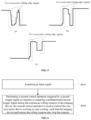
- FIG. 5 is a diagram illustrating a trigger signal according to the first embodiment of the present disclosure.
- the trigger signal can include two consecutive falling edge signals. As shown in FIG. 5 ( b ) , the trigger signal can include two consecutive rising edge signals. As shown in FIG. 5 ( c ) , the trigger signal can include two consecutive rising edge signals. In particular, the difference between FIG. 5 ( b ) and FIG. 5 ( c ) is that the amplitude of the second rising edge signal is different.
- control operation may include at least one of the following implementations.
- the yaw axis motor may be controlled to start and continue to work, such that the imaging device may start and continue the rolling rotation in a clockwise direction.
- the yaw axis motor may be controlled to start and continue to work, such that the imaging device may start and continue the rolling rotation in a counterclockwise direction.
- the yaw axis motor may be controlled to start and continue to work, such that the imaging device may start and continue the rolling rotation in a clockwise direction until the rotation angle reaches a first predetermined angle, then the yaw axis motor may be controlled to stop working.
- the yaw axis motor may be controlled to start and continue to work, such that the imaging device may start and continue the rolling rotation in a counterclockwise direction until the rotation angle reaches a second predetermined angle, then the yaw axis motor may be controlled to stop working.
- the yaw axis motor may be controlled to start and continue to work, such that the imaging device may start and continue the rolling rotation in a clockwise direction. After the rotation angle reaches a third predetermined angle, the yaw axis motor may be controlled to continue to work until the roll angle of the imaging device is approximately 0°, then the yaw axis motor may be controlled to stop working.
- the yaw axis motor may be controlled to start and continue to work, such that the imaging device may start and continue the rolling rotation in a counterclockwise direction. After the rotation angle reaches a fourth predetermined angle, the yaw axis motor may be controlled to continue to work until the roll angle of the imaging device is approximately 0°, then the yaw axis motor may be controlled to stop working.
- the first and second implementations described above may be used to realize the continuous rolling rotation of the imaging device.
- the third and fourth implementations described above may be used to realize the continuous rolling rotation and the automatic rotation stop of the imaging device until the rotation reaches the predetermined angle.
- the fifth and sixth implementations described above may be used to realize the continuous rolling rotation and the automatic rotation stop of the imaging device until the rotation reaches the predetermined angle, and the stopping attitude of the imaging device may be automatically maintained horizontal.
- the roll angle of the imaging device may be approximately 0°, which allows a very small error. That is, the roll angle of the imaging device may be smaller than a predetermined value.
- the present embodiment does not limit the specific value of the predetermined value.
- At least one of the first predetermined angle, the second predetermined angle, the third predetermined angle, and the fourth predetermined angle may be 360°.
- acquiring the input signal may include acquiring the operation direction and control amount of the rocker in response to detecting the user triggering the rocker disposed on the handheld gimbal; and generating the input signal based on the operation direction and control amount of the rocker.
- the user can operate the rocker disposed on the handheld gimbal, thereby inputting the operation direction and control amount of the rocker. Further, the handheld gimbal can acquire the input signal generated based on the operation direction and control amount of the rocker.
- triggering operation performed by the user is not limited in the present embodiment.
- the input signal may be an edge signal
- generating the input signal based on the operation direction and control amount of the rocker may include determining whether the input signal is a rising edge signal or a falling edge signal based on the operation direction; and determining a starting point and an ending point of the amplitude change of the input signal at the rising edge or the falling edge based on the control amount of the rocker.
- moving the rocker to the left may generate a rising edge signal, and moving the rocker to the right may generate a falling edge signal.
- moving the rocker up may generate a rising edge signal, and moving the rocker down may generate a falling edge signal.
- the starting point and ending point of the amplitude change of the input signal at the rising edge or the falling edge may be determined based on the control amount of the rocker. As long as a movement of the rocker is detected, the amplitude change at the rising edge or the falling edge can be a predetermined amplitude.
- the user may move the rocker from an initial position to the right to the maximum position, and the user may move the rocker from the middle position to the right of the rocker to the right to the maximum position.
- the starting point and ending point of the corresponding rising signal may be the same, and both of which may be the predetermined amplitudes.
- acquiring the control amount of the rocker may include acquiring a starting value and an ending value of the control amount based on the initial position and the ending position of the rocker in the operation direction.
- Determining the starting point and ending point of the amplitude change of the input signal at the rising edge or the falling edge based on the control amount of the rocker may include determining the starting point and ending point of the amplitude change of the input signal at the rising edge or the falling edge, respectively, based on starting value and ending value of the control amount.
- the user moves the rocker for the first time, the user moves the rocker from the initial position of the rocker to the right to the maximum position.
- the starting value of the control amount may be 0, and the ending value may be the predetermined maximum value of the control amount.
- the starting point and ending point of the amplitude change of the first rising edge signal may correspond to the predetermined amplitude value.
- the user pulls the rocker back from the maximum position to the right to the middle position to the right, and move the rocker a second time from the middle position to the right.
- the starting value of the control amount may be half of the predetermined maximum value
- the ending value may be the predetermined maximum value of the control amount.
- the starting point and ending point of the amplitude change of the first rising edge signal may correspond to half of the predetermined amplitude value. More specifically, if the user moves the rocker, the amplitude of the second move may be greater than or equal to half of the amplitude of the first move. Therefore, the user may perform the second move without waiting for the rocker to be completely reset after the first move, thereby ensuring a good user experience.
- the triggering operation performed by the user on the rocker disposed on the handheld gimbal may include the user moving the rocker to the right or left for N consecutive times, where N is a positive integer.
- N is not limited in the present embodiment. In some embodiments, N may be equal to two.
- moving the rocker to the right or left twice in succession may trigger the generation of two electrical signals.
- the triggering of the second electrical signal may be determined to be successful.
- the amplitude of the second electrical signal may also be greater than or equal to 1/3, 4/3, 2/3, or other values of the amplitude of the first electrical signal.
- the first move generally has a relatively large amplitude. For example, a full move of the rocker. Subsequently, the rocker needs to be pulled back to continue the second move.
- the starting position of the rocker generally does not need to return to the initial position of the rocker.
- the amplitude of the move will also decrease. Therefore, when it is determined that the amplitude of the second electrical signal is greater than or equal to half of the amplitude of the first electrical signal, it can be determined that the triggering of the second electrical signal is successful. As such, the accuracy of the trigger signal determination may be improved, and the accuracy of the handheld gimbal control operation may be improved.
- the triggering of the electrical signal may be determined to be successful.
- the trigger signal is generally a short time domain signal.
- the electrical signal can be determined as the trigger signal only when the time of the signal edge change of each electrical signal is short enough.
- the accuracy of the trigger signal determination may be improved, which may further improve the accuracy of the handheld gimbal control operation.
- the present embodiment does not limit the specific value of the first predetermined duration.
- the first predetermined duration may be 100 ticks, where tick may indicate the duration of the processing unit.
- the triggering of the electrical signal may be determined to be successful if the time interval between the two electrical signals is less than a second predetermined duration.
- an electrical signal can be determined to be the trigger signal only when the time interval between the two electrical signals is short enough.
- the accuracy of the trigger signal determination may be improved, which may further improve the accuracy of the handheld gimbal control operation.
- the present embodiment does not limit the specific value of the second predetermined duration.
- the second predetermined duration may be 500 ms.
- acquiring the input signal may include receiving the input signal transmitted by a controller of the handheld gimbal, the input signal may be generated after the user perform a trigger operation on the controller.
- the handheld gimbal may be connected to the controller to transmit data and signals.
- the present embodiment does not limit the specific implementation manner of the controller.
- the controller can be a smart terminal, a tablet computer, a desktop computer, a remote controller, etc.
- an application may be pre-installed on the controller.
- the input signal acquired by the handheld gimbal may be the signal transmitted by the controller.
- the controller may include a touch display screen.
- a control area may be displayed on the touch display screen, and the input signal may be generated after the user performs a touch operation in the control area.
- control area may be a virtual rocker displayed on a touch display.
- the method for controlling the handheld gimbal provided in the present embodiment in S 302 , before performing the first control operation triggered by the first trigger signal, the method may further include determining whether the roll angle of the handle of the handheld gimbal is approximately 0°; and performing the first control operation in response to the roll angle of the handle being approximately 0°.
- whether the handle is horizontal may be determined by determining whether the roll angle of the handle of the handheld gimbal is approximately 0°.
- the first control operation may be performed. For specifics, reference may be made to FIG. 4 ( a ) and FIG. 4 ( b ) .
- the imaging device may be controlled to start and continue the rolling rotation, which may improve the imaging and recording effect when the imaging device is rolling and rotating, thereby improving the user experience.
- determining whether the roll angle of the handle is approximately 0° may include acquiring attitude information of the imaging device; acquiring attitude information of the handle based on the attitude information of the imaging device; and determining whether the roll angle of the handle is approximately 0° based on the attitude information of the handle.
- an inertial measurement unit may be disposed in the imaging device, and the attitude information of the imaging device may be acquired through the inertial measurement unit. As such, the attitude information of the handle may be acquired. Further, whether the roll angle of the handle is approximately 0° can be determined based on the attitude information of the handle.
- the method for controlling the handheld gimbal provided in the present embodiment in S 302 , before performing the first control operation triggered by the first trigger signal, the method may further include determining whether the roll angle of the imaging device is approximately 0°; and performing the first control operation in response to the roll angle of the imaging device being approximately 0°.
- whether the imaging device is horizontal may be determined by determining whether the roll angle of the imaging device is approximately 0°.
- the first control operation may be performed.
- FIG. 4 ( a ) , FIG. 4 ( b ) , and FIG. 4 ( c ) are examples of the first control operation.
- the imaging device may be controlled to start and continue the rolling rotation, which may improve the imaging and recording effect when the imaging device is rolling and rotating, thereby improving the user experience.
- determining whether the roll angle of the imaging device is approximately 0° may include acquiring the attitude information of the imaging device; and determining whether the roll angle of the imaging device is approximately 0° based on the attitude information of the imaging device.
- an inertial measurement unit may be disposed in the imaging device, and the attitude information of the imaging device may be acquired through the inertial measurement unit. Further, whether the roll angle of the imaging device is approximately 0° can be determined based on the attitude information of the imaging device.
- the method for controlling the handheld gimbal provided in the present embodiment, in S 302 , before performing the first control operation triggered by the first trigger signal, the method may further include determining whether the pitch angle and/or the yaw angle of the imaging device are approximately 0°; and performing the first control operation in response to the pitch angle and/or the yaw angle of the imaging device being approximately 0°.
- whether the imaging device is tilted upward or downward may be determined by determining whether the pitch angle of the imaging device is approximately 0°. For example, as the attitudes shown in FIG. 4 ( b ) and FIG. 4 ( c ) , the imaging device may be tilted upward. Whether the imaging device is deflected to the left or right may be determined by determining whether the yaw angle of the imaging device is approximately 0°. When the roll angle, pitch angle, and yaw angle of the imaging device are all approximately 0°, the handheld gimbal can be determined to be in the flashlight mode. At this time, the yaw axis motor disposed on the handheld gimbal may be controlled to work continuously, which may realize the continuous rolling rotation of the imaging device around its optical axis.
- the imaging device may be controlled to start and continue the rolling rotation, which may improve the imaging and recording effect when the imaging device is rolling and rotating, thereby improving the user experience.
- approximately 0° means that a very small error is allowed.
- the error may be smaller than a predetermined value.
- the present embodiments do not limit the specific value of the predetermined value.
- the embodiments of the present discolored provide a method for controlling a handheld gimbal including acquiring an input signal, and performing a first control operation triggered by a first trigger signal in response to the input signal being a predetermined first trigger signal.
- the first control operation may be used to control the yaw axis motor disposed on the handheld gimbal to start and continue to work, such that the imaging device carried by the handheld gimbal may be enabled to start and continue a rolling rotation.
- the imaging device may be triggered to start and continue the rolling rotation, which may relieve the user from pressing the control button on the handle at all times, thereby improving the flexibility of the user operation and the user experience.
- FIG. 6 is a flowchart of a method for controlling the handheld gimbal according to a second embodiment of the present disclosure.
- the execution body may be a handheld gimbal, which may be applied to a scene in which an imaging device has been triggered to perform a rolling rotation.
- the method for controlling the handheld gimbal provided in the present embodiment may include:
- the second control operation may be used to control the yaw axis motor that is working to stop working, such that the imaging device performing the rolling rotation may stop the rotation.
- the input signal may be detected to determine whether the input signal is a predetermined trigger signal. If the input signal is the predetermined second trigger signal, the second trigger signal may trigger a second control operation.
- the second control operation may be used to control the yaw axis motor that is working to stop working, such that the imaging device performing the rolling rotation may stop the rotation.
- the rolling rotation of the imaging device may be triggered to automatically stop.
- the user may be prevented from continuously pressing the control button on the handle then releasing the control button to control the imaging device to stop rotating, thereby improving the flexibility of the user control and the user experience.
- the second trigger signal may be received and used to control a motion mode of the imaging device based on a pre-configured corresponding instruction.
- the second trigger signal may trigger one of two motion modes, which may be a continuous clockwise rotation which may stop when the roll angle is 0°, and a continuous counterclockwise rotation which may stop when the roll angle is 0°, respectively.
- a stop trigger button of the handheld gimbal may be disposed on the back of the handle, and the second trigger signal may be generated by double-clicking the stop trigger button.
- the motion mode triggered by the second trigger signal may be the continuous clockwise rotation which may stop until the roll angle is 0°.
- the motion mode triggered by the second trigger signal may be the continuous counterclockwise rotation which may stop until the roll angle is 0°. That is, the imaging device may continue to move to a horizontal position and stop based on the current mode.
- the double-click operation may also generate two electrical signals. If the amplitude of the second electrical signal is greater than or equal to half of the amplitude of the first electrical signal, the triggering of the second electrical signal may be determined to be successful. That is, the amplitude of the second press may be greater than or equal to half of the amplitude of the first press.
- the user experience may be that the user does not need to fully release the control button to completely reset the control button after the first press, and only a certain degree of release may be needed. For example, the second press can be performed by releasing the control button halfway.
- the amplitude of the second electrical signal may be greater than or equal to 1/3, 4/3, 2/3, or other values of the amplitude of the first electrical signal.
- the second control operation may be any one of the following:
- the yaw axis motor that is working may be controlled to stop working immediately such that the imaging device that is performing the rolling rotation may stop the rotation immediately.
- the yaw axis motor that is working may continue to work until the roll angle of the imaging device is 0°, and the yaw axis motor may be controlled to stop working such that the imaging device performing the rolling rotation may be controlled to stop the rotation.
- the imaging device may be stopped immediately.
- the stopping attitude of the imaging device may be maintained as horizontal automatically.
- the roll angle of the imaging device may be approximately 0°, which allows for a very small error. That is, the roll angle of the imaging device may be smaller than a predetermined value.
- the present embodiment does not limit the specific value of the predetermined value.
- the method for controlling a handheld gimbal provided in the first embodiment shown in FIG. 3 to FIG. 5 and the method for controlling a handheld gimbal provided in the present embodiment may be combined with each other.
- the embodiments of the present disclosure provide a method for controlling a handheld gimbal including acquiring an input signal, and performing a second control operation triggered by a second trigger signal in response to determining the input signal to be a predetermined second trigger signal.
- the second control operation may be used to control the yaw axis motor that is working to stop working, such that the imaging device currently performing the rolling rotation may stop the rotation.
- the imaging device performing the rolling rotation may be triggered to stop the rolling rotation, thereby improving the flexibility of the user operation and the user experience.
- FIG. 7 is a structural schematic diagram of the handheld gimbal according to embodiments of the present disclosure.
- the handheld gimbal provided in the present embodiment may be used to execute the control methods of the handheld gimbal provided in the embodiments shown in FIG. 3 to FIG. 6 .
- the handheld gimbal provided in the present embodiment includes a handle 71 , a gimbal 72 , and an imaging device 73 .
- the gimbal 72 may include a gimbal base and a plurality of axis joints, and each axis joint may include a motor and an axis arm drivingly connected to the motor.
- the handle 71 may be connected to the gimbal base, and the imaging device 73 may be disposed on the gimbal.
- the gimbal may further include a processor 74 and a memory 75 .
- the memory 75 may be used to store instructions.
- the processor 74 may be configured to execute the instructions to acquire an input signal; and perform a first control operation triggered by a first trigger signal in response to the input signal being a predetermined first trigger signal.
- the first control operation may be used to control the yaw axis motor disposed on the handheld gimbal to start and continue to work, such that the imaging device carried by the handheld gimbal may be enabled to start and continue the rolling rotation.
- the processor 74 may be further configured to determine whether the roll angle of the handle of the handheld gimbal is approximately 0°; and perform the first control operation in response to the roll angle of the handle being approximately 0°.
- the processor 74 may be further configured to acquire attitude information of the imaging device; acquire attitude information of the handle based on the attitude information of the imaging device; and determine whether the roll angle of the handle is approximately 0° based on the attitude information of the handle.
- the processor 74 may be further configured to determine whether the roll angle of the imaging device is approximately 0°; and perform the first control operation in response to the roll angle of the imaging device being approximately 0°.
- the processor 74 may be further configured to acquire the attitude information of the imaging device; and determine whether the roll angle of the imaging device is approximately 0° based on the attitude information of the imaging device.
- the processor 74 may be further configured to determine whether the pitch angle and/or the yaw angle of the imaging device are approximately 0°; and perform the first control operation in response to the pitch angle and/or the yaw angle of the imaging device being approximately 0°.
- the processor 74 may be further configured to acquire the operation direction and control amount of the rocker in response to detecting the user performing a trigger operation on the rocker disposed on the handheld gimbal; and generate the input signal based on the operation direction and control amount of the rocker.
- the processor 74 may be further configured to determine whether the input signal is a rising edge signal or a falling edge signal based on the operation direction; and determine a starting point and an ending point of the amplitude change of the input signal at the rising edge or the falling edge based on the control amount of the rocker.
- the processor 74 may be further configured to acquire a starting value and an ending value of the control amount based on the initial position and the ending position of the rocker in the operation direction.
- Determining the starting point and ending point of the amplitude change of the input signal at the rising edge or the falling edge based on the control amount of the rocker may include determining the starting point and ending point of the amplitude change of the input signal at the rising edge or the falling edge, respectively, based on the starting value and the ending value of the control amount.
- the trigger operation may include the user moving the rocker to the right or left twice in a row.
- moving the rocker to the right or left twice in a row may trigger two electrical signals.
- the triggering of the second electrical signal may be determined to be successful.
- the processor 74 may be further configured to receive the input signal transmitted by a controller of the handheld gimbal, wherein the input signal may be generated after the user performs a trigger operation on the controller.
- the controller may include a touch display screen.
- a control area may be displayed on the touch display screen, and the input signal may be generated after the user performs a touch operation in the control area.
- the processor 74 may be further configured to determine the first control operation triggered by the first trigger signal based on a predetermined correspondence between the trigger signal and the control operation; and perform the first control operation.
- control operation may include at least one of the following implementations:
- the yaw axis motor may be controlled to start and continue to work, such that the imaging device may start and continue the rolling rotation in a clockwise direction.
- the yaw axis motor may be controlled to start and continue to work, such that the imaging device may start and continue the rolling rotation in a counterclockwise direction.
- the yaw axis motor may be controlled to start and continue to work, such that the imaging device may start and continue the rolling rotation in a clockwise direction until the rotation angle reaches a first predetermined angle, then the yaw axis motor may be controlled to stop working.
- the yaw axis motor may be controlled to start and continue to work, such that the imaging device may start and continue the rolling rotation in a counterclockwise direction until the rotation angle reaches a second predetermined angle, then the yaw axis motor may be controlled to stop working.
- the yaw axis motor may be controlled to start and continue to work, such that the imaging device may start and continue the rolling rotation in a clockwise direction. After the rotation angle reaches a third predetermined angle, the yaw axis motor may be controlled to continue to work until the roll angle of the imaging device is approximately 0°, then the yaw axis motor may be controlled to stop working.
- the yaw axis motor may be controlled to start and continue to work, such that the imaging device may start and continue the rolling rotation in a counterclockwise direction. After the rotation angle reaches a fourth predetermined angle, the yaw axis motor may be controlled to continue to work until the roll angle of the imaging device is approximately 0°, then the yaw axis motor may be controlled to stop working.
- At least one of the first predetermined angle, the second predetermined angle, the third predetermined angle, and the fourth predetermined angle may be 360°.
- the trigger signal may be an edge signal.
- the processor 74 may be further configured to perform a second control operation triggered by a second trigger signal in response to determining the input signal to be a predetermined second trigger signal.
- the second control operation may be used to control the yaw axis motor that is working to stop working, such that the imaging device currently performing the rolling rotation may stop the rotation.
- the second control operation may be any one of the following:
- the yaw axis motor that is working may be controlled to stop working immediately such that the imaging device that is performing the rolling rotation may stop the rotation immediately.
- the yaw axis motor that is working may continue to work until the roll angle of the imaging device is 0°, and the yaw axis motor may be controlled to stop working such that the imaging device performing the rolling rotation may be controlled to stop the rotation.
- the handheld gimbal provided in the present embodiment may be used to execute the handheld gimbal control method provided in the embodiments shown in FIG. 3 to FIG. 6 .
- the technical principles and technical effects are similar, and will not be repeated herein again.
- a method consistent with the disclosure can be implemented in the form of computer program stored in a non-transitory computer-readable storage medium, which can be sold or used as a standalone product.
- the computer program can include instructions that enable a computer device, such as a personal computer, a server, or a network device, to perform part or all of a method consistent with the disclosure, such as one of the exemplary methods described above.
- the storage medium can be any medium that can store program codes, for example, a USB disk, a mobile hard disk, a read-only memory (ROM), a random access memory (RAM), a magnetic disk, or an optical disk.
Landscapes
- Engineering & Computer Science (AREA)
- General Engineering & Computer Science (AREA)
- Mechanical Engineering (AREA)
- Physics & Mathematics (AREA)
- General Physics & Mathematics (AREA)
- Automation & Control Theory (AREA)
- Accessories Of Cameras (AREA)
- Studio Devices (AREA)
- Human Computer Interaction (AREA)
- Manufacturing & Machinery (AREA)
Abstract
Description
Claims (20)
Applications Claiming Priority (1)
| Application Number | Priority Date | Filing Date | Title |
|---|---|---|---|
| PCT/CN2018/115766 WO2020097893A1 (en) | 2018-11-15 | 2018-11-15 | Hand-held gimbal controlling method and hand-held gimbal |
Related Parent Applications (1)
| Application Number | Title | Priority Date | Filing Date |
|---|---|---|---|
| PCT/CN2018/115766 Continuation WO2020097893A1 (en) | 2018-11-15 | 2018-11-15 | Hand-held gimbal controlling method and hand-held gimbal |
Publications (2)
| Publication Number | Publication Date |
|---|---|
| US20210247783A1 US20210247783A1 (en) | 2021-08-12 |
| US12215818B2 true US12215818B2 (en) | 2025-02-04 |
Family
ID=66060259
Family Applications (1)
| Application Number | Title | Priority Date | Filing Date |
|---|---|---|---|
| US17/202,738 Active 2041-02-23 US12215818B2 (en) | 2018-11-15 | 2021-03-16 | Method for controlling handheld gimbal, and handheld gimbal |
Country Status (5)
| Country | Link |
|---|---|
| US (1) | US12215818B2 (en) |
| EP (1) | EP3822534A4 (en) |
| JP (1) | JP7244639B2 (en) |
| CN (1) | CN109642701A (en) |
| WO (1) | WO2020097893A1 (en) |
Families Citing this family (5)
| Publication number | Priority date | Publication date | Assignee | Title |
|---|---|---|---|---|
| WO2021026760A1 (en) * | 2019-08-13 | 2021-02-18 | 深圳市大疆创新科技有限公司 | Cradle head system and control method therefor |
| CN111457233B (en) * | 2020-04-03 | 2024-12-10 | 中山市央果电子科技有限公司 | A multifunctional pan-tilt three-axis stabilizer |
| CN113227931A (en) * | 2020-07-28 | 2021-08-06 | 深圳市大疆创新科技有限公司 | Holder control method, device, equipment and computer readable storage medium |
| CN114352909A (en) * | 2020-10-14 | 2022-04-15 | 杭州零零科技有限公司 | Handheld cloud platform |
| USD1042601S1 (en) * | 2021-08-17 | 2024-09-17 | Guilin Zhishen Information Technology Co., Ltd | Stabilizer |
Citations (26)
| Publication number | Priority date | Publication date | Assignee | Title |
|---|---|---|---|---|
| JPH0469637A (en) | 1990-07-10 | 1992-03-04 | Minolta Camera Co Ltd | Film winding device for camera |
| CN101424946A (en) | 2007-11-02 | 2009-05-06 | 深圳迈瑞生物医疗电子股份有限公司 | Pulse positioning system and method for compensating pulse positioning error thereof |
| CN201400308Y (en) | 2009-05-11 | 2010-02-10 | 董韬 | Unmanned orthophoto holder |
| JP4668474B2 (en) * | 2001-08-01 | 2011-04-13 | Hoya株式会社 | Electronic endoscope system |
| CN203806107U (en) | 2014-03-25 | 2014-09-03 | 江苏海事职业技术学院 | Ship channel detection device |
| WO2014136435A1 (en) | 2013-03-07 | 2014-09-12 | 日本電気株式会社 | Space stabilizing device and space stabilization method |
| CN104881033A (en) | 2015-03-27 | 2015-09-02 | 深圳市大疆创新科技有限公司 | Cloud-tilt control system, cloud-tilt control method, and unmanned aerial vehicle |
| CN105090695A (en) | 2015-09-29 | 2015-11-25 | 深圳市大疆创新科技有限公司 | Handle pan-tilt and control method thereof |
| CN204879354U (en) | 2015-08-18 | 2015-12-16 | 桂林飞宇电子科技有限公司 | Handheld triaxial cloud platform with rocker |
| JP2016099856A (en) | 2014-11-25 | 2016-05-30 | 株式会社Jvcケンウッド | Gimbal device and gimbal device control method |
| JP3204705U (en) * | 2015-03-31 | 2016-06-09 | 點碩科技集團有限公司SwiftCam Technologies Group Company Limited | 360 degree gimbal system |
| CN105759853A (en) | 2016-03-30 | 2016-07-13 | 深圳市哈博森科技有限公司 | Handheld holder and control method |
| CN205610783U (en) | 2016-05-03 | 2016-09-28 | 深圳火星探索科技有限公司 | Take automatic visual tracking's handheld camera shooting pan -tilt that shoots of self stabilization |
| WO2016154996A1 (en) | 2015-04-02 | 2016-10-06 | 深圳市大疆创新科技有限公司 | Stabilized platform, follow-up control system thereof and method therefor |
| US20160301845A1 (en) | 2015-04-10 | 2016-10-13 | Freefly Systems, Inc. | Method, system, and device for controlling a stabilized camera remotely |
| CN205754480U (en) | 2016-06-29 | 2016-11-30 | 深圳火星探索科技有限公司 | A handheld cloud platform with spiral weight counterweight structure |
| CN106444859A (en) | 2016-11-10 | 2017-02-22 | 广州市景沃电子有限公司 | Transverse-rolling-angular-motion-isolated single-axis stable holder and control method |
| CN107094368A (en) | 2017-01-12 | 2017-08-25 | 深圳市大疆灵眸科技有限公司 | Handheld pan-tilt and its control method |
| EP3214354A1 (en) | 2015-12-26 | 2017-09-06 | Wu Han Aibird UAV Co., Ltd | Handheld pan tilt head enabling motion control with rocker |
| EP3236311A1 (en) | 2016-04-20 | 2017-10-25 | Guilin Feiyu Technology Corporation Ltd. | Stable and controllable shooting apparatus |
| WO2017206072A1 (en) | 2016-05-31 | 2017-12-07 | 深圳市大疆灵眸科技有限公司 | Pan-tilt control method and apparatus, and pan-tilt |
| JP2017537333A (en) | 2015-09-16 | 2017-12-14 | エスゼット ディージェイアイ オスモ テクノロジー カンパニー リミテッドSZ DJI Osmo Technology Co., Ltd. | Shooting system |
| CN108323191A (en) | 2018-02-11 | 2018-07-24 | 深圳市大疆创新科技有限公司 | Cloud platform and its control method, unmanned aerial vehicle |
| CN108323192A (en) | 2018-01-05 | 2018-07-24 | 深圳市大疆创新科技有限公司 | Control method of handheld cloud deck and handheld cloud deck |
| CN108375992A (en) | 2018-02-09 | 2018-08-07 | 桂林智神信息技术有限公司 | The control method and control device of hand-held holder |
| CN108700249A (en) | 2017-10-30 | 2018-10-23 | 深圳市大疆创新科技有限公司 | Method for controlling pan-tilt, pan-tilt, control system and movable device |
Family Cites Families (1)
| Publication number | Priority date | Publication date | Assignee | Title |
|---|---|---|---|---|
| PL3236312T3 (en) * | 2016-04-20 | 2019-10-31 | Guilin Feiyu Tech Corporation Ltd | Triaxial stabilizer for mobile phone |
-
2018
- 2018-11-15 CN CN201880003274.2A patent/CN109642701A/en active Pending
- 2018-11-15 WO PCT/CN2018/115766 patent/WO2020097893A1/en not_active Ceased
- 2018-11-15 EP EP18940107.8A patent/EP3822534A4/en not_active Withdrawn
- 2018-11-15 JP JP2021525698A patent/JP7244639B2/en active Active
-
2021
- 2021-03-16 US US17/202,738 patent/US12215818B2/en active Active
Patent Citations (27)
| Publication number | Priority date | Publication date | Assignee | Title |
|---|---|---|---|---|
| JPH0469637A (en) | 1990-07-10 | 1992-03-04 | Minolta Camera Co Ltd | Film winding device for camera |
| JP4668474B2 (en) * | 2001-08-01 | 2011-04-13 | Hoya株式会社 | Electronic endoscope system |
| CN101424946A (en) | 2007-11-02 | 2009-05-06 | 深圳迈瑞生物医疗电子股份有限公司 | Pulse positioning system and method for compensating pulse positioning error thereof |
| CN201400308Y (en) | 2009-05-11 | 2010-02-10 | 董韬 | Unmanned orthophoto holder |
| WO2014136435A1 (en) | 2013-03-07 | 2014-09-12 | 日本電気株式会社 | Space stabilizing device and space stabilization method |
| CN203806107U (en) | 2014-03-25 | 2014-09-03 | 江苏海事职业技术学院 | Ship channel detection device |
| JP2016099856A (en) | 2014-11-25 | 2016-05-30 | 株式会社Jvcケンウッド | Gimbal device and gimbal device control method |
| CN104881033A (en) | 2015-03-27 | 2015-09-02 | 深圳市大疆创新科技有限公司 | Cloud-tilt control system, cloud-tilt control method, and unmanned aerial vehicle |
| JP3204705U (en) * | 2015-03-31 | 2016-06-09 | 點碩科技集團有限公司SwiftCam Technologies Group Company Limited | 360 degree gimbal system |
| WO2016154996A1 (en) | 2015-04-02 | 2016-10-06 | 深圳市大疆创新科技有限公司 | Stabilized platform, follow-up control system thereof and method therefor |
| CN106133631A (en) | 2015-04-02 | 2016-11-16 | 深圳市大疆创新科技有限公司 | Stabilized platform and following control system thereof and method |
| US20160301845A1 (en) | 2015-04-10 | 2016-10-13 | Freefly Systems, Inc. | Method, system, and device for controlling a stabilized camera remotely |
| CN204879354U (en) | 2015-08-18 | 2015-12-16 | 桂林飞宇电子科技有限公司 | Handheld triaxial cloud platform with rocker |
| JP2017537333A (en) | 2015-09-16 | 2017-12-14 | エスゼット ディージェイアイ オスモ テクノロジー カンパニー リミテッドSZ DJI Osmo Technology Co., Ltd. | Shooting system |
| CN105090695A (en) | 2015-09-29 | 2015-11-25 | 深圳市大疆创新科技有限公司 | Handle pan-tilt and control method thereof |
| EP3214354A1 (en) | 2015-12-26 | 2017-09-06 | Wu Han Aibird UAV Co., Ltd | Handheld pan tilt head enabling motion control with rocker |
| CN105759853A (en) | 2016-03-30 | 2016-07-13 | 深圳市哈博森科技有限公司 | Handheld holder and control method |
| EP3236311A1 (en) | 2016-04-20 | 2017-10-25 | Guilin Feiyu Technology Corporation Ltd. | Stable and controllable shooting apparatus |
| CN205610783U (en) | 2016-05-03 | 2016-09-28 | 深圳火星探索科技有限公司 | Take automatic visual tracking's handheld camera shooting pan -tilt that shoots of self stabilization |
| WO2017206072A1 (en) | 2016-05-31 | 2017-12-07 | 深圳市大疆灵眸科技有限公司 | Pan-tilt control method and apparatus, and pan-tilt |
| CN205754480U (en) | 2016-06-29 | 2016-11-30 | 深圳火星探索科技有限公司 | A handheld cloud platform with spiral weight counterweight structure |
| CN106444859A (en) | 2016-11-10 | 2017-02-22 | 广州市景沃电子有限公司 | Transverse-rolling-angular-motion-isolated single-axis stable holder and control method |
| CN107094368A (en) | 2017-01-12 | 2017-08-25 | 深圳市大疆灵眸科技有限公司 | Handheld pan-tilt and its control method |
| CN108700249A (en) | 2017-10-30 | 2018-10-23 | 深圳市大疆创新科技有限公司 | Method for controlling pan-tilt, pan-tilt, control system and movable device |
| CN108323192A (en) | 2018-01-05 | 2018-07-24 | 深圳市大疆创新科技有限公司 | Control method of handheld cloud deck and handheld cloud deck |
| CN108375992A (en) | 2018-02-09 | 2018-08-07 | 桂林智神信息技术有限公司 | The control method and control device of hand-held holder |
| CN108323191A (en) | 2018-02-11 | 2018-07-24 | 深圳市大疆创新科技有限公司 | Cloud platform and its control method, unmanned aerial vehicle |
Non-Patent Citations (3)
| Title |
|---|
| Daren REN et al., "Advanced Road Traffic Management Dictionary", Sep. 1993, Tianjin People's Publishing House, p. 244-245. |
| The World Intellectual Property Organization (WIPO) International Search Report for PCT/CN2018/115766 Aug. 21, 2019 6 Pages (including translation). |
| Xiaofeng Zhang et al., "Electrical control and programmable control technology and applications", Apr. 2010, National Defense Industry Press, p. 30-32. |
Also Published As
| Publication number | Publication date |
|---|---|
| JP7244639B2 (en) | 2023-03-22 |
| EP3822534A1 (en) | 2021-05-19 |
| US20210247783A1 (en) | 2021-08-12 |
| JP2022507227A (en) | 2022-01-18 |
| CN109642701A (en) | 2019-04-16 |
| EP3822534A4 (en) | 2021-07-28 |
| WO2020097893A1 (en) | 2020-05-22 |
Similar Documents
| Publication | Publication Date | Title |
|---|---|---|
| US12215818B2 (en) | Method for controlling handheld gimbal, and handheld gimbal | |
| US11184548B2 (en) | Imaging device, and method and apparatus for controlling the imaging device | |
| JP5981591B1 (en) | Computer program and computer system for controlling object operations in an immersive virtual space | |
| US12425732B2 (en) | Motion trajectory determination and time-lapse photography methods, device, and machine-readable storage medium | |
| US11878240B2 (en) | Method, apparatus, device, and storage medium for perspective rotation | |
| EP3742269A1 (en) | Viewing angle adjustment method and apparatus, storage medium, and electronic apparatus | |
| US11265471B2 (en) | Gimbal control method, device, gimbal, system, and storage medium | |
| CN114710623B (en) | Shooting method based on handheld gimbal, handheld gimbal and storage medium | |
| US20210016177A1 (en) | Method and Apparatus for Controlling Movement of Virtual object in Augmented Reality, and Terminal | |
| US11307677B2 (en) | Method and device for object pointing in virtual reality (VR) scene using a gamepad, and VR apparatus | |
| US20210240059A1 (en) | Imaging method and imaging system | |
| US10866492B2 (en) | Method and system for controlling tracking photographing of stabilizer | |
| US20210004005A1 (en) | Image capture method and device, and machine-readable storage medium | |
| WO2021134644A1 (en) | Gimbal control method and gimbal | |
| WO2020062281A1 (en) | Cradle head control method, cradle head, movable platform and readable storage medium | |
| US11740477B2 (en) | Electronic device, method for controlling electronic device, and non-transitory computer readable storage medium | |
| JP2025016578A (en) | Information processing program, information processing system, and information processing method | |
| CN106803856A (en) | video playing control method and device | |
| WO2022061537A1 (en) | Control method, handheld gimbal, system, and computer-readable storage medium | |
| CN113287297A (en) | Control method, handheld cloud deck, system and computer readable storage medium | |
| JP2016181302A (en) | Computer program and computer system for controlling object operation in immersive virtual space | |
| WO2025255725A1 (en) | Photographing method, system and apparatus, and readable storage medium | |
| CN113272757A (en) | Control method of handheld cloud deck, handheld cloud deck and computer readable storage medium | |
| JP2025114392A (en) | Information processing device, information processing system, information processing program, and information processing method | |
| CN113168191A (en) | Holder control method, handheld holder and computer readable storage medium |
Legal Events
| Date | Code | Title | Description |
|---|---|---|---|
| AS | Assignment |
Owner name: SZ DJI TECHNOLOGY CO., LTD., CHINA Free format text: ASSIGNMENT OF ASSIGNORS INTEREST;ASSIGNORS:SU, TIE;XIE, WENLIN;REEL/FRAME:055605/0291 Effective date: 20201211 |
|
| FEPP | Fee payment procedure |
Free format text: ENTITY STATUS SET TO UNDISCOUNTED (ORIGINAL EVENT CODE: BIG.); ENTITY STATUS OF PATENT OWNER: LARGE ENTITY |
|
| STPP | Information on status: patent application and granting procedure in general |
Free format text: APPLICATION DISPATCHED FROM PREEXAM, NOT YET DOCKETED |
|
| STPP | Information on status: patent application and granting procedure in general |
Free format text: DOCKETED NEW CASE - READY FOR EXAMINATION |
|
| STPP | Information on status: patent application and granting procedure in general |
Free format text: NON FINAL ACTION MAILED |
|
| STPP | Information on status: patent application and granting procedure in general |
Free format text: RESPONSE TO NON-FINAL OFFICE ACTION ENTERED AND FORWARDED TO EXAMINER |
|
| STPP | Information on status: patent application and granting procedure in general |
Free format text: NOTICE OF ALLOWANCE MAILED -- APPLICATION RECEIVED IN OFFICE OF PUBLICATIONS |
|
| ZAAB | Notice of allowance mailed |
Free format text: ORIGINAL CODE: MN/=. |
|
| STPP | Information on status: patent application and granting procedure in general |
Free format text: PUBLICATIONS -- ISSUE FEE PAYMENT RECEIVED |
|
| STPP | Information on status: patent application and granting procedure in general |
Free format text: PUBLICATIONS -- ISSUE FEE PAYMENT VERIFIED |
|
| STCF | Information on status: patent grant |
Free format text: PATENTED CASE |