US12209683B2 - Locking device for a regulator and/or valve - Google Patents
Locking device for a regulator and/or valve Download PDFInfo
- Publication number
- US12209683B2 US12209683B2 US18/206,256 US202318206256A US12209683B2 US 12209683 B2 US12209683 B2 US 12209683B2 US 202318206256 A US202318206256 A US 202318206256A US 12209683 B2 US12209683 B2 US 12209683B2
- Authority
- US
- United States
- Prior art keywords
- assembly
- adjustment head
- housing assembly
- lock portion
- locking
- Prior art date
- Legal status (The legal status is an assumption and is not a legal conclusion. Google has not performed a legal analysis and makes no representation as to the accuracy of the status listed.)
- Active
Links
- 230000004888 barrier function Effects 0.000 claims abstract description 106
- 238000001556 precipitation Methods 0.000 claims abstract description 13
- 230000002093 peripheral effect Effects 0.000 claims description 24
- 229910000831 Steel Inorganic materials 0.000 description 2
- 229910000746 Structural steel Inorganic materials 0.000 description 2
- 230000008901 benefit Effects 0.000 description 2
- 230000005540 biological transmission Effects 0.000 description 2
- 210000002445 nipple Anatomy 0.000 description 2
- 239000010959 steel Substances 0.000 description 2
- 238000003466 welding Methods 0.000 description 2
- 241000272470 Circus Species 0.000 description 1
- 230000007812 deficiency Effects 0.000 description 1
- 238000000034 method Methods 0.000 description 1
- 238000012986 modification Methods 0.000 description 1
- 230000004048 modification Effects 0.000 description 1
Images


Classifications
-
- F—MECHANICAL ENGINEERING; LIGHTING; HEATING; WEAPONS; BLASTING
- F16—ENGINEERING ELEMENTS AND UNITS; GENERAL MEASURES FOR PRODUCING AND MAINTAINING EFFECTIVE FUNCTIONING OF MACHINES OR INSTALLATIONS; THERMAL INSULATION IN GENERAL
- F16K—VALVES; TAPS; COCKS; ACTUATING-FLOATS; DEVICES FOR VENTING OR AERATING
- F16K35/00—Means to prevent accidental or unauthorised actuation
- F16K35/10—Means to prevent accidental or unauthorised actuation with locking caps or locking bars
-
- F—MECHANICAL ENGINEERING; LIGHTING; HEATING; WEAPONS; BLASTING
- F16—ENGINEERING ELEMENTS AND UNITS; GENERAL MEASURES FOR PRODUCING AND MAINTAINING EFFECTIVE FUNCTIONING OF MACHINES OR INSTALLATIONS; THERMAL INSULATION IN GENERAL
- F16K—VALVES; TAPS; COCKS; ACTUATING-FLOATS; DEVICES FOR VENTING OR AERATING
- F16K27/00—Construction of housing; Use of materials therefor
- F16K27/12—Covers for housings
-
- F—MECHANICAL ENGINEERING; LIGHTING; HEATING; WEAPONS; BLASTING
- F16—ENGINEERING ELEMENTS AND UNITS; GENERAL MEASURES FOR PRODUCING AND MAINTAINING EFFECTIVE FUNCTIONING OF MACHINES OR INSTALLATIONS; THERMAL INSULATION IN GENERAL
- F16K—VALVES; TAPS; COCKS; ACTUATING-FLOATS; DEVICES FOR VENTING OR AERATING
- F16K35/00—Means to prevent accidental or unauthorised actuation
- F16K35/06—Means to prevent accidental or unauthorised actuation using a removable actuating or locking member, e.g. a key
-
- Y—GENERAL TAGGING OF NEW TECHNOLOGICAL DEVELOPMENTS; GENERAL TAGGING OF CROSS-SECTIONAL TECHNOLOGIES SPANNING OVER SEVERAL SECTIONS OF THE IPC; TECHNICAL SUBJECTS COVERED BY FORMER USPC CROSS-REFERENCE ART COLLECTIONS [XRACs] AND DIGESTS
- Y10—TECHNICAL SUBJECTS COVERED BY FORMER USPC
- Y10T—TECHNICAL SUBJECTS COVERED BY FORMER US CLASSIFICATION
- Y10T137/00—Fluid handling
- Y10T137/6851—With casing, support, protector or static constructional installations
- Y10T137/7043—Guards and shields
- Y10T137/7062—Valve guards
-
- Y—GENERAL TAGGING OF NEW TECHNOLOGICAL DEVELOPMENTS; GENERAL TAGGING OF CROSS-SECTIONAL TECHNOLOGIES SPANNING OVER SEVERAL SECTIONS OF THE IPC; TECHNICAL SUBJECTS COVERED BY FORMER USPC CROSS-REFERENCE ART COLLECTIONS [XRACs] AND DIGESTS
- Y10—TECHNICAL SUBJECTS COVERED BY FORMER USPC
- Y10T—TECHNICAL SUBJECTS COVERED BY FORMER US CLASSIFICATION
- Y10T137/00—Fluid handling
- Y10T137/7069—With lock or seal
- Y10T137/7256—Locks against rotary motion
Definitions
- the invention generally relates to a locking device for a regulator and/or valve. More particularly, the invention relates to a locking device for a regulator and/or valve that prevents unauthorized access to the adjustment head of the regulator and/or valve.
- Valves and adjustment bolts are often inadequately or altogether unprotected from vandalism, unauthorized access, the weather, and terrorism. Therefore, a need exists for a weather-resistant locking device that can deter vandals and increase the amount of time security and law enforcement personnel has to respond to unauthorized access involving a valve and/or adjustment bolt.
- Valves and adjustment bolts are often inadequately or altogether unprotected from vandalism, unauthorized access, the weather, and terrorism. Therefore, a need exists for a weather-resistant locking device that can deter vandals and increase the amount of time security and law enforcement personnel has to respond to unauthorized access involving a valve and/or adjustment bolt.
- the present invention is directed to a locking device for a regulator and/or valve that substantially obviates one or more problems resulting from the limitations and deficiencies of the related art.
- a locking device for a regulator and/or valve.
- the locking device includes an adjustment head barrier assembly, the adjustment head barrier assembly configured to restrict access to an adjustment head of a regulator and/or valve so as to prevent a tool from engaging the adjustment head; a housing assembly configured to be disposed over the adjustment head barrier assembly, the housing assembly configured to restrict access to the adjustment head barrier assembly and protect the adjustment head barrier assembly from exposure to outdoor precipitation; and a locking assembly configured to removably couple the housing assembly to the adjustment head barrier assembly, the locking assembly configured to prevent unauthorized access to the adjustment head barrier assembly and the adjustment head of the regulator and/or valve.
- the adjustment head barrier assembly comprises a U-bolt and an L-shaped component, the U-bolt configured to be removably attached to a shaft of the regulator and/or valve beneath above the adjustment head of the regulator and/or valve, the L-shaped component configured to be removably attached to the U-bolt, and a top portion of the L-shaped component configured to extend over the adjustment head of the regulator and/or valve so as to prevent the tool from engaging the adjustment head.
- the housing assembly comprises an outer peripheral wall and a top plate attached to the outer peripheral wall, the outer peripheral wall configured to circumscribe the adjustment head barrier assembly, and the top plate configured to be disposed over the adjustment head barrier assembly so as to protect the adjustment head barrier assembly from exposure to the outdoor precipitation.
- the housing assembly further comprises a tubular sleeve member and a cap member removably engaged with the tubular sleeve member, the tubular sleeve member extending from the top plate of the housing assembly, and the cap member configured to be removed from the tubular sleeve member so as to allow a user to gain access to a portion of the locking assembly so that the locking assembly is able to be disengaged, thereby enabling the housing assembly to be removed from the adjustment head barrier assembly.
- the tubular sleeve member of the housing assembly comprises a plurality of external threads and the cap member comprises a plurality of corresponding internal threads, the plurality of corresponding internal threads on the cap member configured to matingly engage with the plurality of external threads on the tubular sleeve member so as to removably attach the cap member to the tubular sleeve member.
- the outer peripheral wall of the housing assembly is circular in shape such that the housing assembly has an overall cylindrical shape.
- the locking assembly comprises a upper female lock portion and a lower male lock portion, the upper female lock portion configured to removably engage with the lower male lock portion so as to secure the housing assembly to the adjustment head barrier assembly.
- the locking assembly further comprises a lock key, and the upper female lock portion is removably engaged with, and disengaged from, the lower male lock portion by means of the lock key.
- the lower male lock portion of the locking assembly is mounted on the adjustment head barrier assembly, and the upper female lock portion of the locking assembly is configured to be disposed over a portion of the housing assembly when the upper female lock portion is engaged with the lower male lock portion, thereby securing the housing assembly to the adjustment head barrier assembly.
- the housing assembly comprises a lock aperture disposed through the top plate, the lock aperture configured to accommodate the lower male lock portion of the locking assembly passing through the top plate.
- the adjustment head of the regulator and/or valve to which access is prevented is in a form of an adjustment bolt head of a pressure regulator.
- the adjustment head of the regulator and/or valve to which access is prevented is in a form of an adjustment bolt head of a valve.
- FIG. 1 is a fragmentary elevation diagrammatic view of an adjustment head barrier assembly and a locking assembly of a locking device for a regulator and/or valve.
- FIG. 2 is a fragmentary top plan diagrammatic view of the adjustment head barrier assembly.
- FIG. 3 is a fragmentary side diagrammatic view of the adjustment head harrier assembly and the locking assembly, wherein the valve and U-bolt have not been shown for clarity purposes.
- FIG. 4 is an elevation diagrammatic view of a housing assembly of the locking device provided with the adjustment head barrier assembly and the locking assembly.
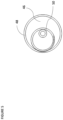
- FIG. 5 is a fragmentary top plan diagrammatic view of the housing assembly.
- FIG. 6 is a fragmentary side perspective diagrammatic view of an adjustment head barrier assembly and a locking assembly of a locking device for a regulator and/or valve.
- FIG. 7 is a fragmentary side perspective diagrammatic view of a housing assembly of the locking device provided over the adjustment head barrier assembly, according to a second illustrative embodiment.
- FIG. 8 is a fragmentary side perspective diagrammatic view of a female lock portion and lock key of the locking assembly of the locking device.
- FIG. 9 is a fragmentary side perspective diagrammatic view of the locking assembly of the locking device provided with the housing assembly, according to the second illustrative embodiment.
- FIG. 10 is a fragmentary side perspective diagrammatic view of a cap member of the housing assembly.
- FIG. 11 is a fragmentary side perspective diagrammatic view of the cap member disposed on the housing assembly of the locking device, according to the second illustrative embodiment.
- the illustrative locking device 10 generally comprises an adjustment head barrier assembly 12 , 34 , the adjustment head barrier assembly 12 , 34 configured to restrict access to an adjustment head 40 of a regulator and/or valve 38 so as to prevent a tool from engaging the adjustment head 40 ; a housing assembly 42 , 46 , 48 configured to be disposed over the adjustment head barrier assembly 12 , 34 , the housing assembly 42 , 46 , 48 configured to restrict access to the adjustment head barrier assembly 12 , 34 and protect the adjustment head barrier assembly 12 , 34 from exposure to outdoor precipitation; and a locking assembly 24 configured to removably couple the housing assembly 42 , 46 , 48 to the adjustment head barrier assembly 12 , 34 , the locking assembly 24 configured to prevent unauthorized access to the adjustment head barrier assembly 12 , 34 and the adjustment head 40 of the regulator and/or valve 38 .
- the adjustment head of the regulator and/or valve to which access is prevented is in a form of an adjustment bolt head 40 of a valve stem 38 .
- the valve stem 38 is configured to be adjusted by a user engaging the adjustment bolt head 40 with a tool (e.g., wrench), and rotating the adjustment bolt head 40 in either a clockwise or counter-clockwise direction to adjust the pressure of the valve.
- a tool e.g., wrench
- the adjustment head barrier assembly 12 , 34 of the locking device 10 comprises a U-bolt 34 and an L-shaped component 12 (e.g., in a form of a steel angle or angle iron).
- the U-bolt 34 is configured to be removably attached to a shaft of the valve 38 above the adjustment head 40 of the valve (see FIG. 1 ).
- the L-shaped component 12 is configured to be removably attached to the U-bolt 34 by means of nuts 36 that threadingly engage with the threaded opposed ends of the U-bolt 34 (refer to FIGS. 1 and 2 ). As shown in the side view of FIG.
- the vertically extending wall of the L-shaped component 12 is provided with a pair of spaced-apart apertures 20 , 22 for accommodating respective opposed ends of the U-bolt 34 .
- a top portion of the L-shaped component 12 is configured to extend over the adjustment head 40 of the valve 38 so as to prevent a tool (e.g., a wrench) from engaging the adjustment head 40 .
- the housing assembly 42 , 46 , 48 comprises an outer peripheral wall 48 and a top plate 46 attached (e.g., welded) to the outer peripheral wall 48 .
- the outer peripheral wall 48 is configured to circumscribe the adjustment head barrier assembly 12 , 34
- the top plate 46 is configured to be disposed over the adjustment head barrier assembly 12 , 34 so as to protect the adjustment head barrier assembly 12 , 34 from exposure to the outdoor precipitation.
- the outer peripheral wall 48 of the housing assembly 42 , 46 , 48 is circular in shape such that the housing assembly 42 , 46 , 48 has an overall cylindrical shape.
- the housing assembly 42 , 46 , 48 operates as a cover to protect the lock and equipment from the elements of the weather and to provide camouflage for the locking assembly and adjustment barrier assembly.
- the housing assembly is not fixed to the adjustment head of a valve or regulator. Therefore, the housing assembly can freely rotate if engaged with a tool and thus cannot be circumvented by a vandal attempting to apply a tool to torque the housing assembly against the adjustment head.
- the housing assembly 42 , 46 , 48 further comprises a tubular sleeve member 42 (e.g., an attachment nipple 42 ) extending from the top plate 46 of the housing assembly 42 , 46 , 48 .
- the housing assembly 42 , 46 , 48 may further comprise a cap member that is removably engaged with the tubular sleeve member 42 .
- the cap member is configured to be removed from the tubular sleeve member 42 so as to allow a user to gain access to a portion of the locking assembly 24 so that the locking assembly 24 is able to be disengaged, thereby enabling the housing assembly 42 , 46 , 48 to be removed from the adjustment head barrier assembly 12 , 34 .
- the tubular sleeve member 42 of the housing assembly 42 , 46 , 48 comprises a plurality of external threads 44 .
- the cap member may comprise a plurality of corresponding internal threads such that the plurality of corresponding internal threads on the cap member are configured to matingly engage with the plurality of external threads 44 on the tubular sleeve member 42 in order to removably attach the cap member to the tubular sleeve member 42 .
- the locking assembly 24 comprises an upper female lock portion 26 and a lower male lock portion 28 (e.g., the locking assembly 24 is in a form of a cylindrical lock assembly or barrel lock assembly).
- the upper female lock portion 26 is configured to removably engage with the lower male lock portion 28 so as to secure the housing assembly 42 , 46 , 48 to the adjustment head barrier assembly 12 , 34 .
- the locking assembly 24 further comprises a lock key 32 , and the upper female lock portion 26 is removably engaged with, and disengaged from, the lower male lock portion 28 by means of the lock key 32 .
- the lower male lock portion 28 of the locking assembly 24 is mounted on the adjustment head barrier assembly 12 , 34 by means of the base portion 30 of the locking assembly 24 being secured within an aperture disposed through the horizontally extending wall of the L-shaped component 12 (e.g., by welding the base portion 30 within the aperture).
- the upper female lock portion 26 of the locking assembly 24 is configured to be disposed over a portion of the top plate 46 of the housing assembly 42 , 46 , 48 when the upper female lock portion 26 is engaged with the lower male lock portion 28 , thereby securing the housing assembly 42 , 46 , 48 to the adjustment head barrier assembly 12 , 34 .
- the portion of the top plate 46 of the housing assembly 42 , 46 , 48 is sandwiched between the bottom edge of the female lock portion 26 and the top surface of the horizontally extending wall of the L-shaped component 12 or the top surface of the lock base portion 30 .
- the housing assembly 42 , 46 , 48 comprises a lock aperture 50 disposed through the top plate 46 of the housing assembly 42 , 46 , 48 .
- the circular lock aperture 50 is configured to accommodate the lower male lock portion 28 of the locking assembly 24 passing through the top plate 46 .
- adjustment head barrier assembly 12 , 34 is in a form of a lock receiver plate assembly, and the adjustment head barrier assembly 12 , 34 forms the base of the locking device 10 .
- FIGS. 7 - 11 A second illustrative embodiment of the locking device for a regulator and/or valve is depicted in FIGS. 7 - 11 .
- the second illustrative embodiment is similar to that of the first illustrative embodiment.
- many elements are common to both such embodiments. For the sake of brevity, the elements that the second embodiment of the locking device has in common with the first embodiment will not be discussed in detail because these components have already been described above.
- the locking device 100 of the second illustrative embodiment generally comprises an adjustment head barrier assembly (not shown), the adjustment head barrier assembly configured to restrict access to an adjustment head (not shown) of a pressure regulator 152 (e.g., a large 8′′ pressure regulator) so as to prevent a tool from engaging the adjustment head; a housing assembly 142 , 146 , 148 , 150 configured to be disposed over the adjustment head barrier assembly, the housing assembly 142 , 146 , 148 , 150 configured to restrict access to the adjustment head barrier assembly and protect the adjustment head barrier assembly from exposure to outdoor precipitation; and a locking assembly 124 configured to removably couple the housing assembly 142 , 146 , 148 , 150 to the adjustment head barrier assembly, the locking assembly 124 configured to prevent unauthorized access to the adjustment head barrier assembly and the adjustment head of the pressure regulator 152 .
- a pressure regulator 152 e.g., a large 8′′ pressure regulator
- the adjustment head of the pressure regulator 152 to which access is prevented is in a form of an adjustment bolt head (not shown) of a pressure regulator 152 .
- the adjustment bolt head of the pressure regulator 152 is configured to be adjusted by a user engaging the adjustment bolt head with a tool (e.g., wrench), and rotating the adjustment bolt head in either a clockwise or counter-clockwise direction to adjust the pressure of the pressure regulator 152 .
- the adjustment head barrier assembly of the locking device 100 comprises a U-bolt (not shown) and an L-shaped component (not shown) (e.g., in a form of a steel angle or angle iron).
- the U-bolt is configured to be removably attached to a shaft of the pressure regulator adjustment bolt (not shown)—beneath the adjustment head of the adjustment bolt.
- the L-shaped component is configured to be removably attached to the U-bolt by means of nuts (not shown) that threadingly engage with the threaded opposed ends of the U-bolt (refer to FIG. 1 ).
- the vertically extending wall of the L-shaped component 102 (not shown) is provided with a pair of spaced-apart apertures for accommodating respective opposed ends of the U-bolt. Also, as shown in FIG. 1 , a top portion of the L-shaped component is configured to extend over the adjustment head of the pressure regulator adjustment bolt so as to prevent a tool (e.g., a wrench) from engaging the adjustment head.
- a tool e.g., a wrench
- the curved portion of the U-bolt engages with the other side of the circular recess beneath the adjustment head of the pressure regulator adjustment bolt
- the housing assembly 142 , 146 , 148 , 150 comprises an outer peripheral wall 148 and a top plate 146 attached (e.g., welded) to the outer peripheral wall 148 .
- the outer peripheral wall 148 is configured to circumscribe the adjustment head barrier assembly
- the top plate 146 is configured to be disposed over the adjustment head barrier assembly so as to protect the adjustment head barrier assembly from exposure to the outdoor precipitation. As shown in the perspective views of FIGS.
- the outer peripheral wall 148 of the housing assembly 142 , 146 , 148 , 150 is circular in shape such that the housing assembly 142 , 146 , 148 , 150 has an overall cylindrical shape.
- the housing assembly 142 , 146 , 148 , 150 further comprises a tubular sleeve member 142 (e.g., an attachment nipple 142 ) extending from the top plate 146 of the housing assembly 142 , 146 , 148 , 150 .
- the housing assembly 142 , 146 , 148 , 150 may further comprise a cap member 150 (e.g., a 11 ⁇ 2 NPT cap) that is removably engaged with the tubular sleeve member 142 .
- the cap member 150 is configured to be removed from the tubular sleeve member 142 so as to allow a user to gain access to a portion of the locking assembly 124 (see FIG. 9 ) so that the locking assembly 124 is able to be disengaged, thereby enabling the housing assembly 142 , 146 , 148 , 150 to be removed from the adjustment head barrier assembly.
- the tubular sleeve member 142 of the housing assembly 142 , 146 , 148 , 150 comprises a plurality of external threads 144 .
- the cap member 150 may comprise a plurality of corresponding internal threads such that the plurality of corresponding internal threads on the cap member 150 are configured to matingly engage with the plurality of external threads 144 on the tubular sleeve member 142 in order to removably attach the cap member 150 to the tubular sleeve member 142 .
- the locking assembly 124 comprises an upper female lock portion 126 and a lower male lock portion 128 (e.g., the locking assembly 124 is in a form of a cylindrical lock assembly or barrel lock assembly).
- the upper female lock portion 126 is configured to removably engage with the lower male lock portion 128 so as to secure the housing assembly 142 , 146 , 148 , 150 to the adjustment head barrier assembly.
- the locking assembly 124 further comprises a lock key 132 , and the upper female lock portion 126 is removably engaged with, and disengaged from, the lower male lock portion 128 (see FIG. 6 ) by means of the lock key 132 .
- the lower male lock portion 128 of the locking assembly 124 is mounted on the adjustment head barrier assembly by means of the base portion (not shown) of the locking assembly 124 being secured within an aperture disposed through the horizontally extending wall of the L-shaped component (e.g., by welding the base portion within the aperture).
- the upper female lock portion 126 of the locking assembly 124 is configured to be disposed over a portion of the top plate 146 of the housing assembly 142 , 146 , 148 , 150 when the upper female lock portion 126 is engaged with the lower male lock portion 128 , thereby securing the housing assembly 142 , 146 , 148 , 150 to the adjustment head barrier assembly.
- the portion of the top plate 146 of the housing assembly 142 , 146 , 148 , 150 is sandwiched between the bottom edge of the female lock portion 126 and the top surface of the horizontally extending wall of the L-shaped component or the top surface of the lock base portion.
- the housing assembly 142 , 146 , 148 , 150 comprises a circular lock aperture disposed through the top plate 146 of the housing assembly 142 , 146 , 148 , 150 .
- the circular lock aperture is configured to accommodate the lower male lock portion 128 of the locking assembly 124 passing through the top plate 146 .
- the afore described locking device 10 , 100 for a regulator and/or valve offers numerous advantages.
- the locking device 10 , 100 conceals valves and adjustment bolts from view, adding a component of camouflage to adjustment elements.
- the locking device 10 , 100 protects the lock and equipment from the elements of the weather.
- the locking device 10 , 100 creates a durable barrier which cannot quickly be removed with common hand tools.
- the locking device 10 , 100 provides workers an easily recognizable “lock out, tag out” method to prevent accidental turning of the valve or adjustment bolt.
- the aforedescribed locking device 10 , 100 can be installed on an existing or new pressure regulator or valve. Also, the locking device 10 , 100 protects the lock and equipment from the elements of the weather by means of the generally weathertight housing assembly (e.g., the spring housing on the top of a pressure regulator is covered by the housing assembly of the locking device 10 , 100 ). Because the locking assembly 24 , 124 is recessed-mounted within the locking device 10 , 100 , it makes it difficult for vandals to break into the device 10 , 100 .
Landscapes
- Engineering & Computer Science (AREA)
- General Engineering & Computer Science (AREA)
- Mechanical Engineering (AREA)
- Control Of Fluid Pressure (AREA)
- Preventing Unauthorised Actuation Of Valves (AREA)
Abstract
Description
Claims (10)
Priority Applications (1)
| Application Number | Priority Date | Filing Date | Title |
|---|---|---|---|
| US18/206,256 US12209683B2 (en) | 2022-11-18 | 2023-06-06 | Locking device for a regulator and/or valve |
Applications Claiming Priority (2)
| Application Number | Priority Date | Filing Date | Title |
|---|---|---|---|
| US202263426428P | 2022-11-18 | 2022-11-18 | |
| US18/206,256 US12209683B2 (en) | 2022-11-18 | 2023-06-06 | Locking device for a regulator and/or valve |
Publications (2)
| Publication Number | Publication Date |
|---|---|
| US20240309969A1 US20240309969A1 (en) | 2024-09-19 |
| US12209683B2 true US12209683B2 (en) | 2025-01-28 |
Family
ID=92714747
Family Applications (1)
| Application Number | Title | Priority Date | Filing Date |
|---|---|---|---|
| US18/206,256 Active US12209683B2 (en) | 2022-11-18 | 2023-06-06 | Locking device for a regulator and/or valve |
Country Status (1)
| Country | Link |
|---|---|
| US (1) | US12209683B2 (en) |
Citations (24)
| Publication number | Priority date | Publication date | Assignee | Title |
|---|---|---|---|---|
| US752818A (en) * | 1904-02-23 | Gas-valve lock | ||
| US1412004A (en) * | 1918-12-31 | 1922-04-04 | Ingraham John | Automobile lock |
| US1920128A (en) * | 1933-04-05 | 1933-07-25 | City Of Jacksonville | Locking attachment |
| US1986128A (en) * | 1933-12-14 | 1935-01-01 | Walworth Patents Inc | Locking device |
| US2377036A (en) * | 1943-04-24 | 1945-05-29 | Reconstruction Finance Corp | Antitampering attachment for valves |
| US3797286A (en) * | 1972-07-26 | 1974-03-19 | Spinello J | Concealed lock for water service cut-off box |
| US4208893A (en) * | 1978-04-26 | 1980-06-24 | Joseph Avrich | Anti-tampering device for valve stems |
| US4534379A (en) * | 1984-04-05 | 1985-08-13 | Parker-Hannifin Corporation | Locking frame for valves |
| US4716747A (en) * | 1986-07-24 | 1988-01-05 | Gas Energy, Inc. | Top locking plug valve |
| US4881388A (en) * | 1988-10-28 | 1989-11-21 | Ronald Pruim | Lock for a brake valve |
| US4911198A (en) * | 1989-07-10 | 1990-03-27 | Philadelphia Control Systems, Inc. | Securing system for automatically operated valve systems |
| US5143114A (en) * | 1991-02-25 | 1992-09-01 | Gte Valenite Corporation | Ball valve lockout mechanism |
| US5735147A (en) * | 1993-04-15 | 1998-04-07 | Cattanach; John T. | System for preventing the movement of vehicles having air brakes |
| US5996613A (en) * | 1997-12-15 | 1999-12-07 | Cav. Uff. Giacomo Cimberio, S.P.A. | Safety and default valve |
| US6220567B1 (en) * | 1999-09-28 | 2001-04-24 | Case Corporation | Interlock mechanism for controlling attachment to a work vehicle |
| US20030024284A1 (en) * | 2001-07-31 | 2003-02-06 | Erickson James E. | Method and apparatus for locking a water main valve |
| US6994106B1 (en) * | 2004-12-13 | 2006-02-07 | Plasticsworks, Inc. | Fire hydrant locking device |
| US20060169324A1 (en) * | 2003-03-06 | 2006-08-03 | Renzo Cimberio | Antitampering ball valve |
| US7287548B2 (en) * | 2003-09-03 | 2007-10-30 | Taema | Integrated valve assembly with means for blocking the actuator |
| US20080143540A1 (en) * | 2006-12-19 | 2008-06-19 | Lalit Savla | Systems, methods, and apparatus for leak detection and prevention |
| US20120211682A1 (en) * | 2011-02-22 | 2012-08-23 | Ming Liang Shiao | Propane tank lock |
| US8561635B2 (en) * | 2010-08-18 | 2013-10-22 | Wcm Industries, Inc. | Hydrant security system |
| US8770220B1 (en) * | 2010-04-16 | 2014-07-08 | King Embry | Hydrant lock |
| US20200191299A1 (en) * | 2018-12-12 | 2020-06-18 | Ckd Corporation | Manual valve and pneumatic device |
-
2023
- 2023-06-06 US US18/206,256 patent/US12209683B2/en active Active
Patent Citations (24)
| Publication number | Priority date | Publication date | Assignee | Title |
|---|---|---|---|---|
| US752818A (en) * | 1904-02-23 | Gas-valve lock | ||
| US1412004A (en) * | 1918-12-31 | 1922-04-04 | Ingraham John | Automobile lock |
| US1920128A (en) * | 1933-04-05 | 1933-07-25 | City Of Jacksonville | Locking attachment |
| US1986128A (en) * | 1933-12-14 | 1935-01-01 | Walworth Patents Inc | Locking device |
| US2377036A (en) * | 1943-04-24 | 1945-05-29 | Reconstruction Finance Corp | Antitampering attachment for valves |
| US3797286A (en) * | 1972-07-26 | 1974-03-19 | Spinello J | Concealed lock for water service cut-off box |
| US4208893A (en) * | 1978-04-26 | 1980-06-24 | Joseph Avrich | Anti-tampering device for valve stems |
| US4534379A (en) * | 1984-04-05 | 1985-08-13 | Parker-Hannifin Corporation | Locking frame for valves |
| US4716747A (en) * | 1986-07-24 | 1988-01-05 | Gas Energy, Inc. | Top locking plug valve |
| US4881388A (en) * | 1988-10-28 | 1989-11-21 | Ronald Pruim | Lock for a brake valve |
| US4911198A (en) * | 1989-07-10 | 1990-03-27 | Philadelphia Control Systems, Inc. | Securing system for automatically operated valve systems |
| US5143114A (en) * | 1991-02-25 | 1992-09-01 | Gte Valenite Corporation | Ball valve lockout mechanism |
| US5735147A (en) * | 1993-04-15 | 1998-04-07 | Cattanach; John T. | System for preventing the movement of vehicles having air brakes |
| US5996613A (en) * | 1997-12-15 | 1999-12-07 | Cav. Uff. Giacomo Cimberio, S.P.A. | Safety and default valve |
| US6220567B1 (en) * | 1999-09-28 | 2001-04-24 | Case Corporation | Interlock mechanism for controlling attachment to a work vehicle |
| US20030024284A1 (en) * | 2001-07-31 | 2003-02-06 | Erickson James E. | Method and apparatus for locking a water main valve |
| US20060169324A1 (en) * | 2003-03-06 | 2006-08-03 | Renzo Cimberio | Antitampering ball valve |
| US7287548B2 (en) * | 2003-09-03 | 2007-10-30 | Taema | Integrated valve assembly with means for blocking the actuator |
| US6994106B1 (en) * | 2004-12-13 | 2006-02-07 | Plasticsworks, Inc. | Fire hydrant locking device |
| US20080143540A1 (en) * | 2006-12-19 | 2008-06-19 | Lalit Savla | Systems, methods, and apparatus for leak detection and prevention |
| US8770220B1 (en) * | 2010-04-16 | 2014-07-08 | King Embry | Hydrant lock |
| US8561635B2 (en) * | 2010-08-18 | 2013-10-22 | Wcm Industries, Inc. | Hydrant security system |
| US20120211682A1 (en) * | 2011-02-22 | 2012-08-23 | Ming Liang Shiao | Propane tank lock |
| US20200191299A1 (en) * | 2018-12-12 | 2020-06-18 | Ckd Corporation | Manual valve and pneumatic device |
Also Published As
| Publication number | Publication date |
|---|---|
| US20240309969A1 (en) | 2024-09-19 |
Similar Documents
| Publication | Publication Date | Title |
|---|---|---|
| US8020579B2 (en) | Fire hydrant security cap closure system | |
| US5199286A (en) | Drum lock device | |
| US3797286A (en) | Concealed lock for water service cut-off box | |
| US6112761A (en) | Fire hydrant locking device and wrench | |
| US5664447A (en) | Valve lockout | |
| US12209683B2 (en) | Locking device for a regulator and/or valve | |
| US8800331B1 (en) | Barrier for preventing tampering with fuel storage tanks | |
| US6920894B1 (en) | Valve security device | |
| US20110036421A1 (en) | Propane tank safety device | |
| US20170284132A1 (en) | Locking Cover Assembly For Preventing Unauthorized Access To A Utility Shut Off Valve | |
| US4356839A (en) | Tamper resistant valve actuator for fire hydrant | |
| US10480680B2 (en) | Tamper resistant locking device for fire hydrant | |
| US5440956A (en) | Unidirectional gas valve shutoff tool and method | |
| US20190293109A1 (en) | Lockout device and a method for its use | |
| US6205827B1 (en) | Regulator torque isolation system and method | |
| US20040154361A1 (en) | Locking cap system | |
| US8240500B2 (en) | Underground tank lock | |
| EP0383374A1 (en) | Publicity cover | |
| US4495910A (en) | Locking valve construction | |
| US4481797A (en) | Tank fill cap locking system | |
| US8806906B1 (en) | Actuator lock-out bracket | |
| US4549569A (en) | Locking valve construction | |
| US20150360858A1 (en) | Tank locking system and method | |
| US5247816A (en) | Locking means, for a faucet | |
| US20180274198A1 (en) | Device for Securing Covers of Drainage Holes and the Like |
Legal Events
| Date | Code | Title | Description |
|---|---|---|---|
| FEPP | Fee payment procedure |
Free format text: ENTITY STATUS SET TO UNDISCOUNTED (ORIGINAL EVENT CODE: BIG.); ENTITY STATUS OF PATENT OWNER: MICROENTITY |
|
| FEPP | Fee payment procedure |
Free format text: ENTITY STATUS SET TO SMALL (ORIGINAL EVENT CODE: SMAL); ENTITY STATUS OF PATENT OWNER: MICROENTITY Free format text: ENTITY STATUS SET TO MICRO (ORIGINAL EVENT CODE: MICR); ENTITY STATUS OF PATENT OWNER: MICROENTITY |
|
| STPP | Information on status: patent application and granting procedure in general |
Free format text: NON FINAL ACTION MAILED |
|
| STPP | Information on status: patent application and granting procedure in general |
Free format text: EX PARTE QUAYLE ACTION MAILED |
|
| STPP | Information on status: patent application and granting procedure in general |
Free format text: RESPONSE TO EX PARTE QUAYLE ACTION ENTERED AND FORWARDED TO EXAMINER |
|
| ZAAB | Notice of allowance mailed |
Free format text: ORIGINAL CODE: MN/=. |
|
| STPP | Information on status: patent application and granting procedure in general |
Free format text: PUBLICATIONS -- ISSUE FEE PAYMENT RECEIVED |
|
| STPP | Information on status: patent application and granting procedure in general |
Free format text: PUBLICATIONS -- ISSUE FEE PAYMENT VERIFIED |
|
| STCF | Information on status: patent grant |
Free format text: PATENTED CASE |