US12209645B2 - Hydraulic drive axle with two-way clutch control - Google Patents
Hydraulic drive axle with two-way clutch control Download PDFInfo
- Publication number
- US12209645B2 US12209645B2 US18/015,825 US202218015825A US12209645B2 US 12209645 B2 US12209645 B2 US 12209645B2 US 202218015825 A US202218015825 A US 202218015825A US 12209645 B2 US12209645 B2 US 12209645B2
- Authority
- US
- United States
- Prior art keywords
- clutch
- plunger
- plunger pump
- wheel set
- driving wheel
- Prior art date
- Legal status (The legal status is an assumption and is not a legal conclusion. Google has not performed a legal analysis and makes no representation as to the accuracy of the status listed.)
- Active
Links
- 230000005540 biological transmission Effects 0.000 claims abstract description 25
- 230000008859 change Effects 0.000 description 7
- 238000011065 in-situ storage Methods 0.000 description 3
- 230000000694 effects Effects 0.000 description 2
- 238000005516 engineering process Methods 0.000 description 2
- 238000012986 modification Methods 0.000 description 2
- 230000004048 modification Effects 0.000 description 2
- 230000009286 beneficial effect Effects 0.000 description 1
- 238000010276 construction Methods 0.000 description 1
- 238000003754 machining Methods 0.000 description 1
- 230000007246 mechanism Effects 0.000 description 1
Images


Classifications
-
- B—PERFORMING OPERATIONS; TRANSPORTING
- B60—VEHICLES IN GENERAL
- B60K—ARRANGEMENT OR MOUNTING OF PROPULSION UNITS OR OF TRANSMISSIONS IN VEHICLES; ARRANGEMENT OR MOUNTING OF PLURAL DIVERSE PRIME-MOVERS IN VEHICLES; AUXILIARY DRIVES FOR VEHICLES; INSTRUMENTATION OR DASHBOARDS FOR VEHICLES; ARRANGEMENTS IN CONNECTION WITH COOLING, AIR INTAKE, GAS EXHAUST OR FUEL SUPPLY OF PROPULSION UNITS IN VEHICLES
- B60K17/00—Arrangement or mounting of transmissions in vehicles
- B60K17/02—Arrangement or mounting of transmissions in vehicles characterised by arrangement, location, or kind of clutch
-
- B—PERFORMING OPERATIONS; TRANSPORTING
- B60—VEHICLES IN GENERAL
- B60K—ARRANGEMENT OR MOUNTING OF PROPULSION UNITS OR OF TRANSMISSIONS IN VEHICLES; ARRANGEMENT OR MOUNTING OF PLURAL DIVERSE PRIME-MOVERS IN VEHICLES; AUXILIARY DRIVES FOR VEHICLES; INSTRUMENTATION OR DASHBOARDS FOR VEHICLES; ARRANGEMENTS IN CONNECTION WITH COOLING, AIR INTAKE, GAS EXHAUST OR FUEL SUPPLY OF PROPULSION UNITS IN VEHICLES
- B60K17/00—Arrangement or mounting of transmissions in vehicles
- B60K17/04—Arrangement or mounting of transmissions in vehicles characterised by arrangement, location or kind of gearing
- B60K17/043—Transmission unit disposed in on near the vehicle wheel, or between the differential gear unit and the wheel
-
- B—PERFORMING OPERATIONS; TRANSPORTING
- B60—VEHICLES IN GENERAL
- B60K—ARRANGEMENT OR MOUNTING OF PROPULSION UNITS OR OF TRANSMISSIONS IN VEHICLES; ARRANGEMENT OR MOUNTING OF PLURAL DIVERSE PRIME-MOVERS IN VEHICLES; AUXILIARY DRIVES FOR VEHICLES; INSTRUMENTATION OR DASHBOARDS FOR VEHICLES; ARRANGEMENTS IN CONNECTION WITH COOLING, AIR INTAKE, GAS EXHAUST OR FUEL SUPPLY OF PROPULSION UNITS IN VEHICLES
- B60K17/00—Arrangement or mounting of transmissions in vehicles
- B60K17/04—Arrangement or mounting of transmissions in vehicles characterised by arrangement, location or kind of gearing
- B60K17/10—Arrangement or mounting of transmissions in vehicles characterised by arrangement, location or kind of gearing of fluid gearing
- B60K17/105—Units comprising at least a part of the gearing and a torque-transmitting axle, e.g. transaxles
-
- B—PERFORMING OPERATIONS; TRANSPORTING
- B60—VEHICLES IN GENERAL
- B60K—ARRANGEMENT OR MOUNTING OF PROPULSION UNITS OR OF TRANSMISSIONS IN VEHICLES; ARRANGEMENT OR MOUNTING OF PLURAL DIVERSE PRIME-MOVERS IN VEHICLES; AUXILIARY DRIVES FOR VEHICLES; INSTRUMENTATION OR DASHBOARDS FOR VEHICLES; ARRANGEMENTS IN CONNECTION WITH COOLING, AIR INTAKE, GAS EXHAUST OR FUEL SUPPLY OF PROPULSION UNITS IN VEHICLES
- B60K17/00—Arrangement or mounting of transmissions in vehicles
- B60K17/34—Arrangement or mounting of transmissions in vehicles for driving both front and rear wheels, e.g. four wheel drive vehicles
- B60K17/356—Arrangement or mounting of transmissions in vehicles for driving both front and rear wheels, e.g. four wheel drive vehicles having fluid or electric motor, for driving one or more wheels
-
- F—MECHANICAL ENGINEERING; LIGHTING; HEATING; WEAPONS; BLASTING
- F16—ENGINEERING ELEMENTS AND UNITS; GENERAL MEASURES FOR PRODUCING AND MAINTAINING EFFECTIVE FUNCTIONING OF MACHINES OR INSTALLATIONS; THERMAL INSULATION IN GENERAL
- F16H—GEARING
- F16H47/00—Combinations of mechanical gearing with fluid clutches or fluid gearing
- F16H47/02—Combinations of mechanical gearing with fluid clutches or fluid gearing the fluid gearing being of the volumetric type
-
- B—PERFORMING OPERATIONS; TRANSPORTING
- B60—VEHICLES IN GENERAL
- B60K—ARRANGEMENT OR MOUNTING OF PROPULSION UNITS OR OF TRANSMISSIONS IN VEHICLES; ARRANGEMENT OR MOUNTING OF PLURAL DIVERSE PRIME-MOVERS IN VEHICLES; AUXILIARY DRIVES FOR VEHICLES; INSTRUMENTATION OR DASHBOARDS FOR VEHICLES; ARRANGEMENTS IN CONNECTION WITH COOLING, AIR INTAKE, GAS EXHAUST OR FUEL SUPPLY OF PROPULSION UNITS IN VEHICLES
- B60K17/00—Arrangement or mounting of transmissions in vehicles
- B60K17/04—Arrangement or mounting of transmissions in vehicles characterised by arrangement, location or kind of gearing
- B60K17/06—Arrangement or mounting of transmissions in vehicles characterised by arrangement, location or kind of gearing of change-speed gearing
-
- B—PERFORMING OPERATIONS; TRANSPORTING
- B62—LAND VEHICLES FOR TRAVELLING OTHERWISE THAN ON RAILS
- B62D—MOTOR VEHICLES; TRAILERS
- B62D11/00—Steering non-deflectable wheels; Steering endless tracks or the like
- B62D11/02—Steering non-deflectable wheels; Steering endless tracks or the like by differentially driving ground-engaging elements on opposite vehicle sides
- B62D11/06—Steering non-deflectable wheels; Steering endless tracks or the like by differentially driving ground-engaging elements on opposite vehicle sides by means of a single main power source
- B62D11/08—Steering non-deflectable wheels; Steering endless tracks or the like by differentially driving ground-engaging elements on opposite vehicle sides by means of a single main power source using brakes or clutches as main steering-effecting means
Definitions
- the present invention relates to the technical field of mechanical equipment transmission mechanisms, and in particular to a hydraulic drive axle with two-way clutch control.
- Construction machinery equipment, garden machinery equipment and transportation machinery equipment all comprise drive systems, transmission systems and power systems.
- processing technology and numerical control technology in the field of machining, more and more mechanical equipment is developing towards the fields of high precision, higher efficiency, high speed and high intelligence.
- higher requirements for the most important transmission systems are also put forward.
- Most transmissions in the existing market are multi-stage gears. Different rotational speeds are achieved through different combinations of planetary gears, or the speed is changed by means of friction plates. This structure is relatively simple and convenient, but it will also lead to the problems of short service life and under-steering of friction wheel transmission or multi-stage planetary gears, which cannot meet the needs of different usage scenarios of users.
- the technical problem to be solved by the present invention is to provide a hydraulic drive axle with two-way clutch control, which can realize stepless speed change, in-situ steering, more stable power output, independent control of runners on both sides and simple internal structure.
- the hydraulic drive axle comprises a housing, wherein a power assembly and a driving assembly connected to the power assembly are provided in the housing;
- the power assembly comprises a plunger pump and a plunger motor;
- the driving assembly comprises a driving wheel set arranged on one side of the plunger motor and connected to the plunger motor, and a clutch matched with the driving wheel set;
- one end of the plunger pump is connected to an external driving device for rotation of the plunger pump;
- the plunger motor is arranged above the plunger pump, and power transmission is realized between the plunger motor and the plunger pump through oil circuit conduction;
- the clutch is arranged on both sides of the driving wheel set and connected to a runner; power is transmitted to the driving wheel set through the plunger pump and the plunger motor; and the clutch on both sides is separately meshed with the driving wheel set to realize independent control of the runner on both sides.
- the plunger pump is rotated by the power input of the external driving device to generate oil pressure, and oil is pressed from the plunger pump to the plunger motor to realize the rotation of the plunger motor so as to complete the power output of the power assembly, which abandons the traditional gear transmission, and can realize stepless speed change, simple internal structure and more stable power output.
- independent clutch control of the runners on both sides can be realized by using the clutch meshed with the driving wheel set, so that the overall structure is simpler.
- the clutch comprises a first clutch and a second clutch, the first clutch and the second clutch are arranged on both sides of the driving wheel set, respectively, and the first clutch is meshed with a first runner on one side for transmission, and the second clutch is meshed with a second runner on the other side for transmission.
- the first clutch is meshed with the first runner for transmission, and the second clutch is meshed with the second runner for transmission, which can realize independent clutch control of the runners on both sides. Therefore, the operating requirements of the hydraulic axle in different situations are realized, and in-situ steering and other operations can be realized.
- the internal structure is simple, and it is easy for users to operate and use.
- the driving wheel set comprises a driving gear and a bevel gear
- the driving gear is connected to and matched with the plunger motor
- the bevel gear is meshed with the driving gear and matched with the clutch
- a rotary rod is rotatably arranged in the housing
- the bevel gear, the first clutch and the second clutch are all coaxially rotatably arranged on the rotary rod.
- a first gear tooth and a second gear tooth are formed on both sides of the driving gear, respectively, a first controller and a second controller are provided on the first clutch and the second clutch, respectively, the first controller is used to control disengagement and engagement between the first clutch and the first gear tooth, and the second controller is used to control disengagement and engagement between the second clutch and the second gear tooth.
- the first controller and the second controller independently control the first clutch and the second clutch, respectively, which is convenient for user operation and use.
- the arrangement of the first gear tooth and the second gear tooth ensures the meshing between the driving gear and the clutch, and the overall structural arrangement is more reasonable.
- the plunger pump comprises a first cylinder and a first plunger
- the first cylinder is rotatably arranged in the swash plate
- the first plunger is synchronously rotatably connected to an input shaft of the external driving device
- the first plunger is annularly arranged in the first cylinder and arranged in the same direction as the input shaft.
- a first thrust bearing is provided between the plunger pump and the swash plate, one end of the first plunger is arranged in the first cylinder, and the other end of the first plunger is matched with the first thrust bearing.
- the first cylinder can rotate synchronously with the input shaft, and it is combined with the first thrust bearing to make the first plunger reciprocate in the first cylinder, realizing the control of oil pressure to ensure that the plunger motor can be driven to operate.
- the swash plate is adjusted, the inclination angle of the first thrust bearing can be changed so as to realize different internal oil pressure control.
- the plunger motor comprises a second cylinder and a second plunger
- the second cylinder is synchronously rotatably connected to an output shaft of the driving wheel set
- the second plunger is annularly arranged in the first cylinder and arranged coaxially with the output shaft.
- An oblique stop groove is provided on the housing
- a second thrust bearing is provided between the second cylinder and the oblique stop groove
- one end of the second plunger is matched with the second thrust bearing
- elastic bodies are provided between the first cylinder and the first plunger, and between the second cylinder and the second plunger.
- the oblique stop groove is arranged obliquely on the housing at a certain angle, and the oil pressure of the plunger pump can drive the second plunger to be matched with the second thrust bearing and reciprocate in the second cylinder, so as to drive the second cylinder to rotate. Therefore, the power output is realized, the overall structure is simple, the power output is stable, and the stepless speed change can be realized.
- one end of the rotary rod and the first clutch are meshed and provided with a linkage gear, and an elastic member for resetting the first clutch is arranged between the first clutch and the linkage gear.
- the meshing engagement between the clutch and the bevel gear can therefore be ensured, and the internal structural arrangement is more reasonable.
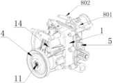
- FIG. 1 is a three-dimensional view of a hydraulic drive axle with two-way clutch control of the present invention
- FIG. 2 is a three-dimensional view of a hydraulic drive axle with two-way clutch control of the present invention in which the bottom is upward;
- FIG. 3 is a schematic structural view of a hydraulic drive axle with two-way clutch control of the present invention in which a housing is removed;
- FIG. 4 is a three-dimensional view of a hydraulic drive axle with two-way clutch control of the present invention in which a housing is removed;
- FIG. 6 is a schematic structural view of a driving assembly of a hydraulic drive axle with two-way clutch control of the present invention.
- a hydraulic drive axle with two-way clutch control comprises a housing 1 , wherein a power assembly 2 and a driving assembly 3 connected to the power assembly 2 are arranged in the housing 1 .
- the power assembly 2 comprises a plunger pump 201 and a plunger motor 202 .
- the driving assembly 3 comprises a driving wheel set 302 arranged on one side of the plunger motor 202 and connected to the plunger motor 202 , and a clutch 301 meshed with the driving wheel set 302 .
- One end of the plunger pump 201 is connected to an external driving device 4 for rotation of the plunger pump 201 .
- the plunger motor 202 is arranged above the plunger pump 201 , and power transmission is realized between the plunger motor 202 and the plunger pump 201 through oil circuit conduction.
- the clutch 301 is arranged on both sides of the driving wheel set 302 and connected to a runner 5 . Power is transmitted to the driving wheel set 302 through the plunger pump 201 and the plunger motor 202 , and the clutch 301 on both sides is separately meshed with the driving wheel set 302 to realize independent control of the runner 5 on both sides.
- the external driving device 4 is a belt pulley
- the clutch 301 is arranged on both sides of the driving wheel set 3 and connected to the runner.
- the clutch 301 comprises a first clutch 311 and a second clutch 321 .
- the first clutch 311 and the second clutch 321 are arranged on both sides of the driving wheel set 302 , respectively.
- the first clutch 311 is meshed with a first runner 501 on one side for transmission
- the second clutch 321 is meshed with a second runner 502 on the other side for transmission.
- the first clutch 311 is meshed with the first runner 501 for transmission
- the second clutch 321 is meshed with the second runner 502 for transmission, which can realize independent clutch control of the runner 5 on both sides. Therefore, the operating requirements of the hydraulic axle in different situations are realized, and in-situ steering and other operations can be realized.
- the internal structure is simple, and it is easy for users to operate and use.
- the driving wheel set 302 comprises a driving gear 312 and a bevel gear 322 , the driving gear 312 is connected to and matched with the plunger motor 202 , and the bevel gear 322 is meshed with the driving gear 312 and matched with the clutch 301 .
- a rotary rod 6 is rotatably arranged in housing 1 , and the bevel gear 322 , the first clutch 311 and the second clutch 321 are all coaxially rotatably arranged on the rotary rod 6 .
- the power of the plunger motor 202 can be transmitted to the clutch 301 and the runner 5 , and the arrangement of the rotary rod 6 can ensure that the internal structural arrangement is more reasonable.
- a first gear tooth 701 and a second gear tooth 702 are formed on both sides of the driving gear 312 , respectively, a first controller 801 and a second controller 802 are provided on the first clutch 311 and the second clutch 321 , respectively, the first controller 801 is used to control disengagement and engagement between the first clutch 311 and the first gear tooth 701 , and the second controller 802 is used to control disengagement and engagement between the second clutch 321 and the second gear tooth 702 .
- the first controller 801 and the second controller 802 independently control the first clutch 311 and the second clutch 321 , respectively, which is convenient for user operation and use.
- the arrangement of the first gear tooth 701 and the second gear tooth 702 ensures the meshing between the driving gear 312 and the clutch 301 , and the overall structural arrangement is more reasonable.
- the plunger pump 201 comprises a first cylinder 901 and a first plunger 1001 , the first cylinder 901 is rotatably arranged in the swash plate 14 , the first plunger 1001 is synchronously rotatably connected to an input shaft 11 of the external driving device 4 , and the first plunger 1001 is annularly arranged in the first cylinder 901 and arranged in the same direction as the input shaft 11 .
- a first thrust bearing 1201 is provided between the plunger pump 201 and the swash plate 14 , one end of first plunger 1001 is arranged in first cylinder 901 , and the other end of the first plunger 1001 is matched with the first thrust bearing 1201 .
- the first cylinder 901 can rotate synchronously with the input shaft 11 , and it is combined with the first thrust bearing 1201 to make the first plunger 1001 reciprocate in the first cylinder 901 , realizing the control of oil pressure to ensure that the plunger motor 202 can be driven to operate.
- the inclination angle of the first thrust bearing 1201 can be changed so as to realize different internal oil pressure control.
- the hydraulic drive axle with two-way clutch control in this embodiment can ensure a more stable power output, and can realize the independent control of the runner on both sides.
- the oil pressure is used to drive the transmission, which abandons the traditional gear meshing transmission, and can realize stepless speed change.
- the output on both sides is controlled independently, so as to meet the needs of different scenarios such as turning while ensuring that the efficiency of power output is higher, the overall structure is simpler and the service life is longer.
Landscapes
- Engineering & Computer Science (AREA)
- Mechanical Engineering (AREA)
- Chemical & Material Sciences (AREA)
- Combustion & Propulsion (AREA)
- Transportation (AREA)
- General Engineering & Computer Science (AREA)
- Motor Power Transmission Devices (AREA)
- Retarders (AREA)
Abstract
Description
Claims (8)
Applications Claiming Priority (5)
| Application Number | Priority Date | Filing Date | Title |
|---|---|---|---|
| CN202221825926.0 | 2022-07-14 | ||
| CN202210834321.6 | 2022-07-14 | ||
| CN202221825926.0U CN217435515U (en) | 2022-07-14 | 2022-07-14 | Hydraulic drive axle with bidirectional clutch control |
| CN202210834321.6A CN115071412B (en) | 2022-07-14 | 2022-07-14 | Hydraulic drive axle of two-way clutch control |
| PCT/CN2022/138344 WO2024011839A1 (en) | 2022-07-14 | 2022-12-12 | Bidirectional clutch control hydraulic driving axle |
Publications (2)
| Publication Number | Publication Date |
|---|---|
| US20240247709A1 US20240247709A1 (en) | 2024-07-25 |
| US12209645B2 true US12209645B2 (en) | 2025-01-28 |
Family
ID=89535376
Family Applications (1)
| Application Number | Title | Priority Date | Filing Date |
|---|---|---|---|
| US18/015,825 Active US12209645B2 (en) | 2022-07-14 | 2022-12-12 | Hydraulic drive axle with two-way clutch control |
Country Status (2)
| Country | Link |
|---|---|
| US (1) | US12209645B2 (en) |
| WO (1) | WO2024011839A1 (en) |
Citations (3)
| Publication number | Priority date | Publication date | Assignee | Title |
|---|---|---|---|---|
| US5339631A (en) * | 1990-08-20 | 1994-08-23 | Kanzaki Kokyukoki Mfg. Co. Ltd. | Axle driving system |
| CN102860179A (en) * | 2007-06-25 | 2013-01-09 | 株式会社久保田 | Work vehicle |
| CN205105640U (en) * | 2015-07-30 | 2016-03-30 | 四川刚毅科技集团有限公司 | Half small -size feeding combine travel drive speed change gear |
Family Cites Families (5)
| Publication number | Priority date | Publication date | Assignee | Title |
|---|---|---|---|---|
| DE3717238A1 (en) * | 1987-05-22 | 1988-12-08 | Teves Gmbh Alfred | Brake system with anti-lock control |
| CN105557103B (en) * | 2016-01-15 | 2018-01-16 | 农业部南京农业机械化研究所 | A kind of high-speed transplanter chassis of hydrostatic drive |
| CN114352698A (en) * | 2022-02-22 | 2022-04-15 | 浙江康利铖机电有限公司 | Zero-steering hydraulic drive axle |
| CN115071412B (en) * | 2022-07-14 | 2023-11-21 | 浙江康利铖机电有限公司 | Hydraulic drive axle of two-way clutch control |
| CN217435515U (en) * | 2022-07-14 | 2022-09-16 | 浙江康利铖机电有限公司 | Hydraulic drive axle with bidirectional clutch control |
-
2022
- 2022-12-12 US US18/015,825 patent/US12209645B2/en active Active
- 2022-12-12 WO PCT/CN2022/138344 patent/WO2024011839A1/en not_active Ceased
Patent Citations (3)
| Publication number | Priority date | Publication date | Assignee | Title |
|---|---|---|---|---|
| US5339631A (en) * | 1990-08-20 | 1994-08-23 | Kanzaki Kokyukoki Mfg. Co. Ltd. | Axle driving system |
| CN102860179A (en) * | 2007-06-25 | 2013-01-09 | 株式会社久保田 | Work vehicle |
| CN205105640U (en) * | 2015-07-30 | 2016-03-30 | 四川刚毅科技集团有限公司 | Half small -size feeding combine travel drive speed change gear |
Also Published As
| Publication number | Publication date |
|---|---|
| WO2024011839A1 (en) | 2024-01-18 |
| US20240247709A1 (en) | 2024-07-25 |
Similar Documents
| Publication | Publication Date | Title |
|---|---|---|
| CN100507320C (en) | Belt type stepless speed changer | |
| US4616478A (en) | Rotatable hydrostatic transmission | |
| TWI610832B (en) | Two-speed transmission having two clutches | |
| TW201725136A (en) | Two-speed transmission for electric vehicle having two clutches | |
| US20130005524A1 (en) | Continuously variable transmission | |
| CN103982652A (en) | Power transferring confluence variable-speed transmission device and hydraulic control system thereof | |
| WO1997034091A1 (en) | Non-stage transmission | |
| CN217435515U (en) | Hydraulic drive axle with bidirectional clutch control | |
| CN114352698A (en) | Zero-steering hydraulic drive axle | |
| CN108843787B (en) | A variable speed transmission device for a crawler transport vehicle | |
| US12209645B2 (en) | Hydraulic drive axle with two-way clutch control | |
| CN105090427B (en) | A kind of mechanical-hydraulic mixing stepless speed change device of use secondary component | |
| CN106958640A (en) | There is the transmission device of fan liquid_viscosity regulator function for rear power endless-track vehicle | |
| CN217422091U (en) | Zero-steering hydraulic drive axle | |
| CN115071412B (en) | Hydraulic drive axle of two-way clutch control | |
| CN209324967U (en) | A Tractor Continuously Variable Transmission with Single Planetary Row Confluence | |
| CN101245832A (en) | Single planet wheel reversing mechanism | |
| CN108916346B (en) | A kind of variable speed transmission method for crawler transport vehicle | |
| CN210912599U (en) | Separately-arranged proportional differential steering transmission of tracked vehicle | |
| CN207935078U (en) | The differential gear of flashlight complex controll pumps | |
| CN108150412A (en) | The differential gear pump of flashlight complex controll | |
| CN104088973A (en) | Gear transmission hydraulic speed regulation infinitely variable transmission | |
| CN115355299A (en) | High-low speed full-time four-wheel drive transmission with HST | |
| CN101245831A (en) | Double-planet wheel type reversing mechanism | |
| CN223459851U (en) | Small-sized coaxial double-transmission mechanism |
Legal Events
| Date | Code | Title | Description |
|---|---|---|---|
| AS | Assignment |
Owner name: ZHEJIANG KC MECHANICAL & ELECTRICAL CO.,LTD., CHINA Free format text: ASSIGNMENT OF ASSIGNORS INTEREST;ASSIGNORS:YING, HAOYU;SUN, XIAOWEI;LU, YISHENG;REEL/FRAME:062380/0001 Effective date: 20230109 |
|
| FEPP | Fee payment procedure |
Free format text: ENTITY STATUS SET TO UNDISCOUNTED (ORIGINAL EVENT CODE: BIG.); ENTITY STATUS OF PATENT OWNER: SMALL ENTITY |
|
| FEPP | Fee payment procedure |
Free format text: ENTITY STATUS SET TO SMALL (ORIGINAL EVENT CODE: SMAL); ENTITY STATUS OF PATENT OWNER: SMALL ENTITY |
|
| STPP | Information on status: patent application and granting procedure in general |
Free format text: NON FINAL ACTION MAILED |
|
| STPP | Information on status: patent application and granting procedure in general |
Free format text: RESPONSE TO NON-FINAL OFFICE ACTION ENTERED AND FORWARDED TO EXAMINER |
|
| STPP | Information on status: patent application and granting procedure in general |
Free format text: NOTICE OF ALLOWANCE MAILED -- APPLICATION RECEIVED IN OFFICE OF PUBLICATIONS |
|
| STPP | Information on status: patent application and granting procedure in general |
Free format text: PUBLICATIONS -- ISSUE FEE PAYMENT RECEIVED |
|
| STPP | Information on status: patent application and granting procedure in general |
Free format text: PUBLICATIONS -- ISSUE FEE PAYMENT VERIFIED |
|
| STCF | Information on status: patent grant |
Free format text: PATENTED CASE |