US12208931B2 - Package supporting device and unmanned package transporter - Google Patents
Package supporting device and unmanned package transporter Download PDFInfo
- Publication number
- US12208931B2 US12208931B2 US18/317,103 US202318317103A US12208931B2 US 12208931 B2 US12208931 B2 US 12208931B2 US 202318317103 A US202318317103 A US 202318317103A US 12208931 B2 US12208931 B2 US 12208931B2
- Authority
- US
- United States
- Prior art keywords
- drive
- package
- state
- side restricting
- contacting
- Prior art date
- Legal status (The legal status is an assumption and is not a legal conclusion. Google has not performed a legal analysis and makes no representation as to the accuracy of the status listed.)
- Active, expires
Links
- 238000003780 insertion Methods 0.000 claims description 19
- 230000037431 insertion Effects 0.000 claims description 19
- 230000000694 effects Effects 0.000 description 4
- 230000032258 transport Effects 0.000 description 2
- 238000012986 modification Methods 0.000 description 1
- 230000004048 modification Effects 0.000 description 1
- 230000002093 peripheral effect Effects 0.000 description 1
Images


Classifications
-
- B—PERFORMING OPERATIONS; TRANSPORTING
- B64—AIRCRAFT; AVIATION; COSMONAUTICS
- B64D—EQUIPMENT FOR FITTING IN OR TO AIRCRAFT; FLIGHT SUITS; PARACHUTES; ARRANGEMENT OR MOUNTING OF POWER PLANTS OR PROPULSION TRANSMISSIONS IN AIRCRAFT
- B64D9/00—Equipment for handling freight; Equipment for facilitating passenger embarkation or the like
- B64D9/003—Devices for retaining pallets or freight containers
-
- B—PERFORMING OPERATIONS; TRANSPORTING
- B64—AIRCRAFT; AVIATION; COSMONAUTICS
- B64U—UNMANNED AERIAL VEHICLES [UAV]; EQUIPMENT THEREFOR
- B64U60/00—Undercarriages
- B64U60/40—Undercarriages foldable or retractable
-
- B—PERFORMING OPERATIONS; TRANSPORTING
- B64—AIRCRAFT; AVIATION; COSMONAUTICS
- B64C—AEROPLANES; HELICOPTERS
- B64C39/00—Aircraft not otherwise provided for
- B64C39/02—Aircraft not otherwise provided for characterised by special use
-
- B—PERFORMING OPERATIONS; TRANSPORTING
- B64—AIRCRAFT; AVIATION; COSMONAUTICS
- B64C—AEROPLANES; HELICOPTERS
- B64C39/00—Aircraft not otherwise provided for
- B64C39/02—Aircraft not otherwise provided for characterised by special use
- B64C39/024—Aircraft not otherwise provided for characterised by special use of the remote controlled vehicle type, i.e. RPV
-
- B—PERFORMING OPERATIONS; TRANSPORTING
- B64—AIRCRAFT; AVIATION; COSMONAUTICS
- B64U—UNMANNED AERIAL VEHICLES [UAV]; EQUIPMENT THEREFOR
- B64U10/00—Type of UAV
- B64U10/10—Rotorcrafts
- B64U10/13—Flying platforms
-
- B—PERFORMING OPERATIONS; TRANSPORTING
- B64—AIRCRAFT; AVIATION; COSMONAUTICS
- B64U—UNMANNED AERIAL VEHICLES [UAV]; EQUIPMENT THEREFOR
- B64U60/00—Undercarriages
- B64U60/50—Undercarriages with landing legs
-
- B—PERFORMING OPERATIONS; TRANSPORTING
- B64—AIRCRAFT; AVIATION; COSMONAUTICS
- B64U—UNMANNED AERIAL VEHICLES [UAV]; EQUIPMENT THEREFOR
- B64U2101/00—UAVs specially adapted for particular uses or applications
- B64U2101/60—UAVs specially adapted for particular uses or applications for transporting passengers; for transporting goods other than weapons
- B64U2101/64—UAVs specially adapted for particular uses or applications for transporting passengers; for transporting goods other than weapons for parcel delivery or retrieval
Definitions
- the present disclosure relates to a package supporting device and an unmanned package transporter.
- an object of the present disclosure is to provide a package supporting device and an unmanned package transporter which are capable of preventing or suppressing dropping of packages during flight.
- a package supporting device includes: a base, a small unmanned aerial vehicle being attached to an upper portion of the base; plural ground contacting portions that are configured to contact a landing surface in a state of having landed; plural package supporting portions provided at an underside of the base, the package supporting portions supporting a package; a drive portion that is operable in a first state to cause each of the package supporting portions to move toward the package, and is operable in a second state to cause each of the package supporting portions to move away from the package; and a restricting portion that is provided independently from the drive portion, that allows operation of the drive portion in a state in which the ground contacting portions are contacting a landing surface, and, in a state in which the ground contacting portions do not contact a landing surface, restricts operation of the drive portion in at least the second state.
- the package supporting portions move toward the package when the drive portion is operated in the first state. This enables the package to be supported by the package supporting portions. Moreover, in a case in which the ground contacting portions are contacting a landing surface, the package supporting portions move away from the package when the drive portion is operated in the second state. This enables the package to be moved away from the package supporting portions. In a state in which the ground contacting portions are contacting a landing surface, the restricting portion allows operation of the drive portion.
- the restricting portion restricts operation of the drive portion in at least the second state. This enables the movement of the package supporting portions away from the package to be prevented or suppressed in a state in which the ground contacting portions are not contacting a landing surface. As a result, dropping of the package during flight can be prevented or suppressed.
- a package supporting device is the package supporting device according to the first aspect, wherein: the restricting portion includes: a drive-portion-side restricting portion that is displaceable between a first position that restricts operation of the drive portion in at least the second state, and a second position that allows operation of the drive portion, a ground-contacting-portion-side restricting portion that is provided at one of the ground contacting portions, and a connecting portion that connects the drive-portion-side restricting portion and the ground-contacting-portion-side restricting portion; in a case in which the ground-contacting-portion-side restricting portion contacts a landing surface, the connecting portion displaces, and the drive-portion-side restricting portion displaces from the first position to the second position; and in a case in which the ground-contacting-portion-side restricting portion does not contact a landing surface, the connecting portion displaces, and the drive-portion-side restricting portion displaces from the second position to the first position.
- the connecting portion displaces, and the drive-portion-side restricting portion displaces from the first position to the second position.
- the restricting portion allows operation of the drive portion.
- the connecting portion displaces, and the drive-portion-side restricting portion displaces from the second position to the first position.
- the restricting portion restricts operation of the drive portion in at least the second state. This enables dropping of the package during flight to be prevented or suppressed.
- a package supporting device is the package supporting device according to the second aspect, further including a biasing member that continuously biases the drive-portion-side restricting portion toward the first position.
- the drive-portion-side restricting portion is continuously biased toward the first position by the biasing member. This enables dropping of the package during flight to be prevented or suppressed even in a case in which, for example, an operational failure arises at the ground-contacting-portion-side restricting portion or the connecting portion.
- a package supporting device is the package supporting device according to the second aspect, wherein: the drive-portion-side restricting portion includes a pressing portion that is pressed against a member configuring the drive portion in a state in which the drive-portion-side restricting portion is positioned at the first position; and operation of the drive portion is restricted by the pressing portion being pressed against the member configuring the drive portion.
- the pressing portion of the drive-portion-side restricting portion is pressed against the member configuring the drive portion, enabling operation of the drive portion to be restricted.
- a package supporting device is the package supporting device according to the second aspect, wherein: the drive-portion-side restricting portion includes plural first ratchet teeth that protrude toward the drive portion; the drive portion includes plural second ratchet teeth that protrude toward the drive-portion-side restricting portion and that engage with the plural first ratchet teeth of the drive-portion-side restricting portion positioned at the first position; in a state in which the plural first ratchet teeth and the plural second ratchet teeth are engaged with each other, operation of the drive portion in the second state is restricted; and in a case in which the drive portion is in the first state in the state in which the plural first ratchet teeth and the plural second ratchet teeth are engaged with each other, operation of the drive portion in the first state is allowed by the plural second ratchet teeth moving over the plural first ratchet teeth.
- the plural first ratchet teeth of the drive-portion-side restricting portion and the plural second ratchet teeth of the drive portion are engaged with each other, enabling operation of the drive portion in the second state to be restricted. Moreover, even if the plural first ratchet teeth of the drive-portion-side restricting portion and the plural second ratchet teeth of the drive portion are engaged with each other, operation of the drive portion in the first state can be allowed.
- a package supporting device is the package supporting device according to the second aspect, wherein: the drive-portion-side restricting portion includes: a fixed cam portion that is non-movable with respect to the base, a movable cam portion that is connected to the connecting portion and is displaceable with respect to the base, and an insertion portion that protrudes from the drive portion and that is inserted through the fixed cam portion and the movable cam portion; in a state in which the movable cam portion is disposed at a position at which movement of the insertion portion is restricted by the fixed cam portion and the movable cam portion, operation of the drive portion is restricted; and in a state in which the movable cam portion is disposed at a position at which the insertion portion is movable along the fixed cam portion and the movable cam portion, operation of the drive portion is allowed.
- the movable cam portion being disposed at a position at which movement of the insertion portion of the drive portion is restricted by the fixed cam portion and the movable cam portion, operation of the drive portion can be restricted.
- the movable cam portion being disposed at a position at which the insertion portion of the drive portion can move along the fixed cam portion and the movable cam portion, operation of the drive portion can be allowed.
- An unmanned package transporter includes: a small unmanned aerial vehicle; a base, the small unmanned aerial vehicle being attached to an upper portion of the base; plural ground contacting portions that are configured to contact a landing surface in a state of having landed; plural package supporting portions provided at an underside of the base, the package supporting portions supporting a package; a drive portion that is operable in a first state to cause each of the package supporting portions to move toward the package, and is operable in a second state to cause each of the package supporting portions to move away from the package; and a restricting portion that is provided independently from the drive portion, that allows operation of the drive portion in a state in which the ground contacting portions are contacting a landing surface, and, in a state in which the ground contacting portions do not contact a landing surface, restricts operation of the drive portion in at least the second state.
- the unmanned package transporter enables a package, which is supported, to be transported by a small unmanned aerial vehicle flying. Moreover, in the unmanned package transporter according to the seventh aspect, in a case in which the ground contacting portions contact a landing surface, the package supporting portions move toward the package when the drive portion is operated in the first state. This enables the package to be supported by the package supporting portions. Moreover, in a case in which the ground contacting portions contact a landing surface, the package supporting portions move away from the package when the drive portion is operated in the second state. This enables the package to be moved away from the package supporting portions. In a state in which the ground contacting portions are contacting a landing surface, the restricting portion allows operation of the drive portion.
- the restricting portion restricts operation of the drive portion in at least the second state. This enables the movement of the package supporting portions away from the package to be prevented or suppressed in a state in which the ground contacting portions are not contacting a landing surface. As a result, dropping of the package during flight can be prevented or suppressed.
- the package supporting device and the unmanned package transporter according to the present disclosure have the excellent advantageous effect of being able to prevent or suppress dropping of packages during flight.
- FIG. 23 is a perspective view schematically illustrating a restricting portion of another aspect, and illustrates a state in which movement of an insertion portion is restricted by a fixed cam portion and a movable cam portion;
- FIG. 24 is a perspective view schematically illustrating a restricting portion of another aspect, and illustrates a state in which an insertion portion is movable along a fixed cam portion and a movable cam portion;
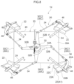
- the unmanned package transporter 10 of the present exemplary embodiment includes a small unmanned aerial vehicle 12 and a package supporting device 14 attached to an underside of the small unmanned aerial vehicle 12 .
- the package supporting device 14 includes an aerial vehicle fixing portion 16 to which the small unmanned aerial vehicle 12 is fixed, and a pair of ground contacting portions 18 that contact a landing surface in a state of having landed.
- the pair of ground contacting portions 18 each include a ground contacting portion main body 18 A that extends in a horizontal direction and contacts a landing surface, and a central leg portion 18 B that extends upward from a central portion in a longitudinal direction of the ground contacting portion main body 18 A.
- a landing surface is a surface on which the unmanned package transporter 10 lands, and is a ground surface, a drone port, a vehicle roof, a loading platform, or the like.
- the plate 20 is formed in a plate shape with a vertical direction serving as a thickness direction of the plate 20 , and has a substantially rectangular shape in which each side of a rectangle is curved inward when viewed from above.
- the leg portions 22 are respectively attached to the four corners of the plate 20 .
- Each of the leg portions 22 includes two abutting portions 22 A with space therebetween in the horizontal direction, which is a direction orthogonal to the vertical direction, an upper connecting portion 22 B connecting upper ends of the two abutting portions 22 A in the horizontal direction, and a lower connecting portion 22 C connecting lower ends of the two abutting portions 22 A in the horizontal direction.
- the two abutting portions 22 A are formed in a round bar shape with an axial direction thereof extending in the vertical direction.
- the upper connecting portion 22 B is formed in a plate shape extending horizontally with the vertical direction serving as a thickness direction of the upper connecting portion 22 B.
- each of the four protruding arm portions 32 B opposite to the rotating portion 32 A is connected to one end of a respective one of the four outer links 34 via a ball joint.
- the other end of each of the four outer links 34 is connected to a respective one of four slide brackets 46 , which are described below, via a ball joint.
- each of the leg portions 22 is supported by a respective one of the linear guides 24 via a slide portion 42 , a rotation supporting portion 44 , and the like. More specifically, as illustrated in FIG. 6 , each of the leg portions 22 is supported by a respective one of the linear guides 24 via a slide portion 42 , a slide bracket 46 , and a rotation supporting portion 44 .
- the slide portion 42 is engaged with the linear guide 24 .
- the slide portion 42 is configured to slide (move) along the longitudinal direction of the linear guide 24 .
- the slide bracket 46 is fixed to a lower portion of the slide portion 42 .
- the other end of the outer link 34 is connected via a ball joint to an end of the slide bracket 46 opposite to the slide portion 42 .
- a rotation restricting spring 48 serving as a rotation restricting portion, is provided between the upper connecting portion 22 B of each of the leg portions 22 and a respective one of the slide brackets 46 .
- the rotation restricting spring 48 is, for example, a torsion spring.
- the rotation supporting portion 44 is inserted through the rotation restricting spring 48 .
- one end 48 A of the rotation restricting spring 48 is engaged with a hole formed in the upper connecting portion 22 B.
- the other end 48 B of the rotation restricting spring 48 is engaged with a hole formed in the slide bracket 46 .
- the rotation restricting spring 48 is deformed so as to allow rotation of the leg portion 22 with the vertical direction as an axial direction.
- the package supporting device 14 can support the package 30 in a state in which the ground contacting portions 18 are in contact with a landing surface (a state in which the unmanned package transporter 10 has landed).
- each of the leg portions 22 is maintained in an orientation determined by a respective one of the rotation restricting springs 48 (see FIG. 6 ). This enables unnecessary rotation of the respective leg portions 22 , with the vertical direction as an axial direction, to be restricted in a state in which the respective leg portions 22 do not support the package 30 .
- the orientation of each leg portion 22 in relation to a respective one of the linear guides 24 in a state in which the respective leg portions 22 do not support the package 30 is referred to as a standard orientation A 1 .
- the package 30 includes a rectangular upper surface 30 A and a rectangular lower surface 30 B (see FIG. 11 ), and four side surfaces 30 C connecting the upper surface 30 A and the lower surface 30 B in the vertical direction.
- the four side surfaces 30 C two side surfaces 30 C having a smaller dimension in the horizontal direction are referred to as first side surfaces 30 C 1
- second side surfaces 30 C 2 two side surfaces 30 C having a dimension in the horizontal direction that is larger than the dimension in the horizontal direction of the first side surfaces 30 C 1 are referred to as second side surfaces 30 C 2 .
- aspect ratio a ratio (hereafter referred to as an “aspect ratio”) of a dimension in a horizontal direction of the first side faces 30 C 1 to a dimension in a horizontal direction of the second side faces 30 C 2 .
- an operating state of the drive portion 40 which is caused by rotation of the output shaft 28 A of the actuator 28 to one side (in the direction of the arrow C 1 ), is referred to as a first state (an operating state when a package is supported).
- the two abutting portions 22 A of each of the leg portions 22 abut the adjacent first side surface 30 C 1 and second side surface 30 C 2 , respectively.
- the respective leg portions 22 are substantially prevented from rotating from the standard orientation A 1 .
- the standard orientation A 1 of each of the leg portions 22 is set in accordance with the package 30 having a standard aspect ratio. Note that the package 30 is not illustrated in FIG. 12 and FIG. 13 .
- each leg portion 22 when the two abutting portions 22 A of each of the leg portions 22 abut the adjacent first side surface 30 C 1 and second side surface 30 C 2 , respectively, the lower connecting portion 22 C of each leg portion 22 is disposed along the lower surface 30 B of the package 30 . This enables the four corner portions 30 D of the package 30 to be supported by the respective leg portions 22 .
- each small unmanned aerial vehicle 12 when each small unmanned aerial vehicle 12 is activated, each small unmanned aerial vehicle 12 flies together with the package supporting device 14 . This enables the package 30 , which is supported by the package supporting device 14 , to be transported by air.
- an operating state of the drive portion 40 which is caused by rotation of the output shaft 28 A of the actuator 28 to the other side (the side opposite to the direction of the arrow C 1 ), is referred to as a second state (an operating state when a package is unloaded).
- FIG. 14 shows a package 30 with a flat aspect ratio in which the dimension in the horizontal direction of the first side surfaces 30 C 1 is smaller than the dimension in the horizontal direction of the first side surfaces 30 C 1 of the package 30 with a standard aspect ratio. Explanation follows regarding movement of the respective leg portions 22 when the respective leg portions 22 support a package 30 with a flat aspect ratio.
- each of the leg portions 22 rotates from the standard orientation A 1 to one side, the other abutting portion 22 A of each of the leg portions 22 abuts the second side surface 30 C 2 .
- the lower connecting portion 22 C of each of the leg portions 22 is disposed along the lower surface 30 B of the package 30 with a flat aspect ratio. This enables the four corner portions 30 D of the package 30 with a flat aspect ratio to be supported by the respective leg portions 22 .
- the package supporting device 14 of the unmanned package transporter 10 of the present exemplary embodiment can support a package 30 of different sizes and shapes (aspect ratios).
- the package supporting device 14 of the unmanned package transporter 10 of the present exemplary embodiment described above includes a restricting portion 50 for preventing or suppressing dropping of the package 30 during flight.
- the restricting portion 50 includes a ground-contacting-portion-side restricting portion 52 provided at one of the ground contacting portions 18 , a drive-portion-side restricting portion 53 provided at the side of the drive portion 40 , and a connecting portion 54 that connects the ground-contacting-portion-side restricting portion 52 and the drive-portion-side restricting portion 53 .
- the ground-contacting-portion-side restricting portion 52 includes a base 56 fixed to a boundary portion between the ground contacting portion main body 18 A and the central leg portion 18 B of one of the ground contacting portions 18 , and a ground contacting arm 58 that is supported by the base 56 .
- the base 56 is provided with an outer tube locking portion 56 A, to which one end portion of an outer tube 64 , which is described below, is locked.
- One end portion of the ground contacting arm 58 is connected to a lower end portion of the base 56 via a non-illustrated pin so as to be rotatable with the horizontal direction as an axial direction.
- a protruding portion 58 A protruding downward is formed at an intermediate portion between the end portion on one side and the end portion on another side of the ground contacting arm 58 .
- the connecting portion 54 includes the outer tube 64 which is formed in a tubular shape, and the cable 66 which is inserted through the outer tube 64 .
- one end of the outer tube 64 is locked by the outer tube locking portion 56 A which is provided at the base 56 .
- the other end of the outer tube 64 is locked by an outer tube locking portion 68 which is fixed to the plate 20 (see FIG. 3 ).
- one end of the cable 66 is locked to the other end of the ground contacting arm 58 .
- the other end of the cable 66 is locked to the end of the pressing portion 60 A of the pressing arm 60 which is opposite to the extending portion 60 B.
- the cable 66 is in a state in which it has pressed the pressing arm 60 toward the side opposite to the rotating portion 32 A of the central link 32 .
- the pressing portion 60 A of the pressing arm 60 is in a state such that it is not contacting the rotating portion 32 A of the central link 32 .
- the position of the pressing arm 60 in this state is referred to as the allowing position D 1 , which serves as a second position.
- the respective leg portions 22 can be moved toward the package 30 or away from the package 30 by actuating the drive portion 40 .
Landscapes
- Engineering & Computer Science (AREA)
- Aviation & Aerospace Engineering (AREA)
- Mechanical Engineering (AREA)
- Remote Sensing (AREA)
- Warehouses Or Storage Devices (AREA)
Abstract
Description
Claims (6)
Applications Claiming Priority (2)
| Application Number | Priority Date | Filing Date | Title |
|---|---|---|---|
| JP2022-083382 | 2022-05-20 | ||
| JP2022083382A JP7622696B2 (en) | 2022-05-20 | 2022-05-20 | Luggage support device and unmanned luggage transporter |
Publications (2)
| Publication Number | Publication Date |
|---|---|
| US20230373665A1 US20230373665A1 (en) | 2023-11-23 |
| US12208931B2 true US12208931B2 (en) | 2025-01-28 |
Family
ID=88777626
Family Applications (1)
| Application Number | Title | Priority Date | Filing Date |
|---|---|---|---|
| US18/317,103 Active 2043-05-16 US12208931B2 (en) | 2022-05-20 | 2023-05-15 | Package supporting device and unmanned package transporter |
Country Status (3)
| Country | Link |
|---|---|
| US (1) | US12208931B2 (en) |
| JP (1) | JP7622696B2 (en) |
| CN (1) | CN117087860A (en) |
Families Citing this family (5)
| Publication number | Priority date | Publication date | Assignee | Title |
|---|---|---|---|---|
| US11225325B1 (en) * | 2021-03-12 | 2022-01-18 | DroneUp, LLC | Payload delivery and drop device for unmanned aerial vehicle for automatic release upon surface contact |
| ES2958407B2 (en) * | 2022-07-13 | 2025-02-12 | Genoves Ramirez Pedro | UNMANNED AERIAL SYSTEM FOR AUTONOMOUS DELIVERY AND REMOVAL OF PRODUCTS |
| US12312085B2 (en) * | 2023-05-18 | 2025-05-27 | Performance Drone Works Llc | Mechanical release device for unmanned aerial vehicle drop-payload |
| CN117864472B (en) * | 2024-03-13 | 2024-05-28 | 扬州市职业大学(扬州开放大学) | A multi-rotor UAV landing gear |
| CN119568413B (en) * | 2025-02-07 | 2025-05-02 | 山西航佳航空科技股份有限公司 | Multi-rotor unmanned aerial vehicle for logistics transportation and application method thereof |
Citations (9)
| Publication number | Priority date | Publication date | Assignee | Title |
|---|---|---|---|---|
| US5868357A (en) * | 1995-03-20 | 1999-02-09 | Gabriel; Edwin Zenith | Automatically-actuated cargo and personnel scooping apparatus with strain gauges, fingers and sensors |
| US6179357B1 (en) * | 1999-03-01 | 2001-01-30 | Edwin Zenith Gabriel | Automatically-actuated cargo and personnel scooping apparatus with pivoted extensions, magnets and buckets |
| WO2020194533A1 (en) | 2019-03-26 | 2020-10-01 | 楽天株式会社 | Unmanned aircraft and waterproof container |
| WO2020217662A1 (en) | 2019-04-26 | 2020-10-29 | パナソニックIpマネジメント株式会社 | Home delivery box, home delivery system, flying body, and home delivery method |
| US11345051B2 (en) * | 2016-10-21 | 2022-05-31 | Beijing Jingdong Shangke Information Technology Co., Ltd. | Automatic unloading carrier and unmanned aerial vehicle |
| JP2022190972A (en) | 2021-06-15 | 2022-12-27 | トヨタ自動車株式会社 | Baggage holding device and unmanned baggage conveying machine |
| US20230091849A1 (en) * | 2021-09-22 | 2023-03-23 | Insitu, Inc. a subsidiary of The Boeing Company | Package delivery systems and related methods |
| US20230211883A1 (en) * | 2021-12-30 | 2023-07-06 | Flyby Robotics, Inc. | Winch delivery system |
| US20230331386A1 (en) * | 2022-04-14 | 2023-10-19 | Workhorse Group Inc. | Unmanned aerial vehicle delivery systems |
Family Cites Families (5)
| Publication number | Priority date | Publication date | Assignee | Title |
|---|---|---|---|---|
| FR2952549B1 (en) * | 2009-11-13 | 2011-11-25 | Parrot | SUPPORT BLOCK FOR A ROTARY SAIL DRONE MOTOR |
| JP7205823B2 (en) * | 2018-12-05 | 2023-01-17 | 株式会社ニックス | Gripping mechanism and conveying device |
| US11643203B2 (en) * | 2018-12-27 | 2023-05-09 | Rakuten Group, Inc. | Unmanned aerial vehicle with package carrier |
| JP7336931B2 (en) * | 2019-09-19 | 2023-09-01 | Ihi運搬機械株式会社 | drone port |
| US11225325B1 (en) | 2021-03-12 | 2022-01-18 | DroneUp, LLC | Payload delivery and drop device for unmanned aerial vehicle for automatic release upon surface contact |
-
2022
- 2022-05-20 JP JP2022083382A patent/JP7622696B2/en active Active
-
2023
- 2023-03-24 CN CN202310304126.7A patent/CN117087860A/en active Pending
- 2023-05-15 US US18/317,103 patent/US12208931B2/en active Active
Patent Citations (10)
| Publication number | Priority date | Publication date | Assignee | Title |
|---|---|---|---|---|
| US5868357A (en) * | 1995-03-20 | 1999-02-09 | Gabriel; Edwin Zenith | Automatically-actuated cargo and personnel scooping apparatus with strain gauges, fingers and sensors |
| US6179357B1 (en) * | 1999-03-01 | 2001-01-30 | Edwin Zenith Gabriel | Automatically-actuated cargo and personnel scooping apparatus with pivoted extensions, magnets and buckets |
| US11345051B2 (en) * | 2016-10-21 | 2022-05-31 | Beijing Jingdong Shangke Information Technology Co., Ltd. | Automatic unloading carrier and unmanned aerial vehicle |
| WO2020194533A1 (en) | 2019-03-26 | 2020-10-01 | 楽天株式会社 | Unmanned aircraft and waterproof container |
| US20210171195A1 (en) | 2019-03-26 | 2021-06-10 | Rakuten, Inc. | Unmanned aerial vehicle and waterproof container |
| WO2020217662A1 (en) | 2019-04-26 | 2020-10-29 | パナソニックIpマネジメント株式会社 | Home delivery box, home delivery system, flying body, and home delivery method |
| JP2022190972A (en) | 2021-06-15 | 2022-12-27 | トヨタ自動車株式会社 | Baggage holding device and unmanned baggage conveying machine |
| US20230091849A1 (en) * | 2021-09-22 | 2023-03-23 | Insitu, Inc. a subsidiary of The Boeing Company | Package delivery systems and related methods |
| US20230211883A1 (en) * | 2021-12-30 | 2023-07-06 | Flyby Robotics, Inc. | Winch delivery system |
| US20230331386A1 (en) * | 2022-04-14 | 2023-10-19 | Workhorse Group Inc. | Unmanned aerial vehicle delivery systems |
Also Published As
| Publication number | Publication date |
|---|---|
| JP2023171136A (en) | 2023-12-01 |
| US20230373665A1 (en) | 2023-11-23 |
| JP7622696B2 (en) | 2025-01-28 |
| CN117087860A (en) | 2023-11-21 |
Similar Documents
| Publication | Publication Date | Title |
|---|---|---|
| US12208931B2 (en) | Package supporting device and unmanned package transporter | |
| JP2023171135A (en) | Luggage support device and unmanned load transfer machine | |
| KR102312786B1 (en) | Container Transport Facility | |
| US12496959B2 (en) | Remotely adjustable captive beam system | |
| EP4242138A1 (en) | Storage system with guided plate based lifting apparatus for payload loading-unloading on storage rack | |
| KR102450289B1 (en) | Vessel conveying equipment and vessel conveying equipment | |
| JP2007106406A (en) | Fallable type guide device and perpendicular restraint device for air cargo system | |
| EP3587266B1 (en) | Managed routing and actuation harness system | |
| TW201816918A (en) | Item transport device | |
| JP2016216137A5 (en) | ||
| US20070224026A1 (en) | Transferring system | |
| CN113666037B (en) | Article handling device | |
| KR20190028111A (en) | Slidable luggage board assembly of vehicle | |
| JP2017513036A (en) | Cargo fixing system and method for transferring a substrate in a lithography system | |
| CN111629964A (en) | Unmanned plane | |
| CN110654788B (en) | Cargo carrying device and sorting AGV | |
| US8496205B2 (en) | Dual pivot pallet type cargo load restraint | |
| KR102097414B1 (en) | a manipulator type unloading apparatus | |
| WO2017155992A1 (en) | Loading ramp | |
| US12234031B2 (en) | Cargo restraint system with individually retractable restraints | |
| KR20220088646A (en) | Expandable deck and truck having the same | |
| JPH03128810A (en) | Device to automatically guide and arrange freight container | |
| KR102747526B1 (en) | Moving vehicle for land and air delivery | |
| US12384540B2 (en) | Cargo handling system repositionable side guide | |
| KR102755700B1 (en) | Hand of industrial robot and industrial robot |
Legal Events
| Date | Code | Title | Description |
|---|---|---|---|
| AS | Assignment |
Owner name: TOYOTA JIDOSHA KABUSHIKI KAISHA, JAPAN Free format text: ASSIGNMENT OF ASSIGNORS INTEREST;ASSIGNOR:KIYOKAMI, HIROAKI;REEL/FRAME:063636/0488 Effective date: 20230112 |
|
| FEPP | Fee payment procedure |
Free format text: ENTITY STATUS SET TO UNDISCOUNTED (ORIGINAL EVENT CODE: BIG.); ENTITY STATUS OF PATENT OWNER: LARGE ENTITY |
|
| STPP | Information on status: patent application and granting procedure in general |
Free format text: DOCKETED NEW CASE - READY FOR EXAMINATION |
|
| STPP | Information on status: patent application and granting procedure in general |
Free format text: NON FINAL ACTION MAILED |
|
| STPP | Information on status: patent application and granting procedure in general |
Free format text: RESPONSE TO NON-FINAL OFFICE ACTION ENTERED AND FORWARDED TO EXAMINER |
|
| STPP | Information on status: patent application and granting procedure in general |
Free format text: AWAITING TC RESP., ISSUE FEE NOT PAID |
|
| STPP | Information on status: patent application and granting procedure in general |
Free format text: NOTICE OF ALLOWANCE MAILED -- APPLICATION RECEIVED IN OFFICE OF PUBLICATIONS |
|
| STPP | Information on status: patent application and granting procedure in general |
Free format text: PUBLICATIONS -- ISSUE FEE PAYMENT VERIFIED |
|
| STCF | Information on status: patent grant |
Free format text: PATENTED CASE |