US12206357B2 - Automated attachment of solar components - Google Patents
Automated attachment of solar components Download PDFInfo
- Publication number
- US12206357B2 US12206357B2 US18/480,330 US202318480330A US12206357B2 US 12206357 B2 US12206357 B2 US 12206357B2 US 202318480330 A US202318480330 A US 202318480330A US 12206357 B2 US12206357 B2 US 12206357B2
- Authority
- US
- United States
- Prior art keywords
- structural component
- mounting devices
- module mounting
- fastener
- fastening
- Prior art date
- Legal status (The legal status is an assumption and is not a legal conclusion. Google has not performed a legal analysis and makes no representation as to the accuracy of the status listed.)
- Active
Links
Images


Classifications
-
- H—ELECTRICITY
- H02—GENERATION; CONVERSION OR DISTRIBUTION OF ELECTRIC POWER
- H02S—GENERATION OF ELECTRIC POWER BY CONVERSION OF INFRARED RADIATION, VISIBLE LIGHT OR ULTRAVIOLET LIGHT, e.g. USING PHOTOVOLTAIC [PV] MODULES
- H02S30/00—Structural details of PV modules other than those related to light conversion
- H02S30/10—Frame structures
-
- B—PERFORMING OPERATIONS; TRANSPORTING
- B23—MACHINE TOOLS; METAL-WORKING NOT OTHERWISE PROVIDED FOR
- B23P—METAL-WORKING NOT OTHERWISE PROVIDED FOR; COMBINED OPERATIONS; UNIVERSAL MACHINE TOOLS
- B23P21/00—Machines for assembling a multiplicity of different parts to compose units, with or without preceding or subsequent working of such parts, e.g. with program control
- B23P21/002—Machines for assembling a multiplicity of different parts to compose units, with or without preceding or subsequent working of such parts, e.g. with program control the units stationary whilst being composed
-
- F—MECHANICAL ENGINEERING; LIGHTING; HEATING; WEAPONS; BLASTING
- F24—HEATING; RANGES; VENTILATING
- F24S—SOLAR HEAT COLLECTORS; SOLAR HEAT SYSTEMS
- F24S25/00—Arrangement of stationary mountings or supports for solar heat collector modules
- F24S25/60—Fixation means, e.g. fasteners, specially adapted for supporting solar heat collector modules
- F24S25/65—Fixation means, e.g. fasteners, specially adapted for supporting solar heat collector modules for coupling adjacent supporting elements, e.g. for connecting profiles together
-
- H—ELECTRICITY
- H02—GENERATION; CONVERSION OR DISTRIBUTION OF ELECTRIC POWER
- H02S—GENERATION OF ELECTRIC POWER BY CONVERSION OF INFRARED RADIATION, VISIBLE LIGHT OR ULTRAVIOLET LIGHT, e.g. USING PHOTOVOLTAIC [PV] MODULES
- H02S20/00—Supporting structures for PV modules
-
- H—ELECTRICITY
- H02—GENERATION; CONVERSION OR DISTRIBUTION OF ELECTRIC POWER
- H02S—GENERATION OF ELECTRIC POWER BY CONVERSION OF INFRARED RADIATION, VISIBLE LIGHT OR ULTRAVIOLET LIGHT, e.g. USING PHOTOVOLTAIC [PV] MODULES
- H02S20/00—Supporting structures for PV modules
- H02S20/30—Supporting structures being movable or adjustable, e.g. for angle adjustment
-
- F—MECHANICAL ENGINEERING; LIGHTING; HEATING; WEAPONS; BLASTING
- F24—HEATING; RANGES; VENTILATING
- F24S—SOLAR HEAT COLLECTORS; SOLAR HEAT SYSTEMS
- F24S25/00—Arrangement of stationary mountings or supports for solar heat collector modules
- F24S2025/01—Special support components; Methods of use
- F24S2025/014—Methods for installing support elements
-
- F—MECHANICAL ENGINEERING; LIGHTING; HEATING; WEAPONS; BLASTING
- F24—HEATING; RANGES; VENTILATING
- F24S—SOLAR HEAT COLLECTORS; SOLAR HEAT SYSTEMS
- F24S25/00—Arrangement of stationary mountings or supports for solar heat collector modules
- F24S25/60—Fixation means, e.g. fasteners, specially adapted for supporting solar heat collector modules
- F24S2025/6005—Fixation means, e.g. fasteners, specially adapted for supporting solar heat collector modules by screwed connection
-
- F—MECHANICAL ENGINEERING; LIGHTING; HEATING; WEAPONS; BLASTING
- F24—HEATING; RANGES; VENTILATING
- F24S—SOLAR HEAT COLLECTORS; SOLAR HEAT SYSTEMS
- F24S25/00—Arrangement of stationary mountings or supports for solar heat collector modules
- F24S25/60—Fixation means, e.g. fasteners, specially adapted for supporting solar heat collector modules
- F24S2025/6009—Fixation means, e.g. fasteners, specially adapted for supporting solar heat collector modules by deforming the material, e.g. by crimping or clinching
-
- F—MECHANICAL ENGINEERING; LIGHTING; HEATING; WEAPONS; BLASTING
- F24—HEATING; RANGES; VENTILATING
- F24S—SOLAR HEAT COLLECTORS; SOLAR HEAT SYSTEMS
- F24S25/00—Arrangement of stationary mountings or supports for solar heat collector modules
- F24S25/60—Fixation means, e.g. fasteners, specially adapted for supporting solar heat collector modules
- F24S2025/6011—Fixation means, e.g. fasteners, specially adapted for supporting solar heat collector modules by welding or brazing
-
- Y—GENERAL TAGGING OF NEW TECHNOLOGICAL DEVELOPMENTS; GENERAL TAGGING OF CROSS-SECTIONAL TECHNOLOGIES SPANNING OVER SEVERAL SECTIONS OF THE IPC; TECHNICAL SUBJECTS COVERED BY FORMER USPC CROSS-REFERENCE ART COLLECTIONS [XRACs] AND DIGESTS
- Y02—TECHNOLOGIES OR APPLICATIONS FOR MITIGATION OR ADAPTATION AGAINST CLIMATE CHANGE
- Y02E—REDUCTION OF GREENHOUSE GAS [GHG] EMISSIONS, RELATED TO ENERGY GENERATION, TRANSMISSION OR DISTRIBUTION
- Y02E10/00—Energy generation through renewable energy sources
- Y02E10/40—Solar thermal energy, e.g. solar towers
- Y02E10/47—Mountings or tracking
-
- Y—GENERAL TAGGING OF NEW TECHNOLOGICAL DEVELOPMENTS; GENERAL TAGGING OF CROSS-SECTIONAL TECHNOLOGIES SPANNING OVER SEVERAL SECTIONS OF THE IPC; TECHNICAL SUBJECTS COVERED BY FORMER USPC CROSS-REFERENCE ART COLLECTIONS [XRACs] AND DIGESTS
- Y02—TECHNOLOGIES OR APPLICATIONS FOR MITIGATION OR ADAPTATION AGAINST CLIMATE CHANGE
- Y02E—REDUCTION OF GREENHOUSE GAS [GHG] EMISSIONS, RELATED TO ENERGY GENERATION, TRANSMISSION OR DISTRIBUTION
- Y02E10/00—Energy generation through renewable energy sources
- Y02E10/50—Photovoltaic [PV] energy
Definitions
- the present disclosure generally relates to a system and method of automated attachment of solar components.
- PV photovoltaic
- the PV modules may be mounted in rows on solar trackers that direct an orientation of the PV modules such that the orientation of the PV modules changes throughout a day.
- the PV modules may be placed in an outdoor location such that the PV modules may receive sunlight with little or no obstruction.
- a method may include positioning one or more PV module mounting devices along a length of a structural component.
- the method may include specifying one or more parameters related to fastening the PV module mounting devices to the structural component, the one or more parameters indicating a spacing between the PV module mounting devices.
- the method may include fastening, by an automated attachment equipment, the PV module mounting devices to the structural component based on the specified parameters and moving the PV module mounting devices fastened to the structural component to an assembly platform.
- the assembly platform may be part of or coupled to a transportable component.
- fastening, by the automated attachment equipment, the PV module mounting devices to the structural component may include using an automatic feeder that sequentially provides PV module mounting devices to be fastened to the structural component, the automatic feeder moving the PV module mounting devices along an axis while the structural component remains stationary.
- fastening, by the automated attachment equipment, the PV module mounting devices to the structural component may include using an automatic feeder that sequentially provides PV module mounting devices to be fastened to the structural component, the automatic feeder moving the structural component along an axis while the PV module mounting devices remain stationary.
- the automated attachment equipment may be configured to move along at least one of three axes, the three axes including a first axis along an x-direction, a second axis along a y-direction, and a third axis along a z-direction.
- specifying the one or more parameters may be based on a size or an orientation of the PV module mounting device.
- fastening the PV module mounting devices to the structural component may involve a flow drill fastening process that includes driving a fastener into a surface of one of the PV module mounting devices that is in contact with the structural component or through a hole in the surface of the one of the PV module mounting devices that is in contact with the structural component.
- the flow drill fastening process may include rotating the fastener at a rotational rate that forms a flowing material from the structural component or the surface of each of the PV module mounting devices and forming threads in a hole formed by driving the fastener into the surface of one of the PV module mounting devices that is in contact with the structural component by decreasing the rotational rate of the fastener.
- fastening the PV module mounting devices to the structural component includes may involve driving a drill bit through a surface of the structural component that is aligned with a surface of one of the PV module mounting devices to form an aligned hole through the structural component and the PV module mounting device and inserting a blind fastener through the aligned hole.
- fastening the PV module mounting devices to the structural component may include spot welding the PV module mounting devices to the structural component or securing each of the PV module mounting devices to the structural component using a clinch joint.
- a photovoltaic (PV) module mounting device assembly system may include one or more PV module mounting devices positioned along a length of a structural component and an automated attachment equipment that is configured to fasten the PV module mounting devices to the structural component.
- the PV module mounting device assembly system may include an assembly platform onto which the PV module mounting devices fastened to the structural component are moved after fastening.
- the assembly platform may be part of or coupled to a transportable component.
- the PV module mounting device assembly system may further include an automatic feeder that sequentially provides the PV module mounting devices to be fastened to the structural component, the automatic feeder moving the structural component along an axis while the PV module mounting devices remain stationary.
- the PV module mounting device assembly system may further include an automatic feeder that sequentially provides the PV module mounting devices to be fastened to the structural component, the automatic feeder moving the PV module mounting devices along an axis while the structural component remains stationary.
- the automated attachment equipment may be configured to move along at least one of three axes, the three axes including a first axis along an x-direction, a second axis along a y-direction, and a third axis along a z-direction.
- the PV module mounting devices may be fastened to the structural component according to one or more parameters specified based on a size or an orientation of a PV module.
- the automated attachment equipment may be configured to use a flow drill fastening process that includes driving a fastener into a surface of one of the PV module mounting devices that is in contact with the structural component or through a hole in the surface of the one of the PV module mounting devices that is in contact with the structural component.
- the flow drill fastening process may involve rotating the fastener at a rotational rate that forms a flowing material from the structural component or the surface of each of the PV module mounting devices and forming threads in a hole formed by driving the fastener into the surface of one of the PV module mounting devices that is in contact with the structural component by decreasing the rotational rate of the fastener.
- the automated attachment equipment may be configured to drive a drill bit through a surface of the structural component that is aligned with a surface of one of the PV module mounting devices to form an aligned hole through the structural component and the PV module mounting device and insert a blind fastener through the aligned hole.
- the automated attachment equipment may be configured to spot weld the PV module mounting devices to the structural component or secure each of the PV module mounting devices to the structural component using a clinch joint.
- a system may include one or more processors and one or more non-transitory computer-readable storage media configured to store instructions that, in response to being executed, cause a photovoltaic (PV) module mounting device assembly system to perform operations.
- the operations may include instructing one or more robotic components to position one or more PV module mounting devices along a length of a structural component.
- the operations may also include specifying one or more parameters related to fastening the PV module mounting devices to the structural component, the one or more parameters indicating a spacing between the PV module mounting devices.
- the method may include instructing automated attachment equipment to fasten the PV module mounting devices to the structural component based on the specified parameters and instructing the one or more robotic components to move the PV module mounting devices fastened to the structural component along an assembly platform.
- fastening the PV module mounting devices to the structural component may involve a flow drill fastening process that includes instructing the automated attachment equipment to drive a fastener into a surface of one of the PV module mounting devices that is in contact with the structural component or through a hole in the surface of the one of the PV module mounting devices that is in contact with the structural component.
- the flow drill fastening process may include instructing the automated attachment equipment to rotate the fastener at a rotational rate that forms a flowing material from the structural component or the surface of each of the PV module mounting devices and instructing the automated attachment equipment to decrease the rotational rate of the fastener to facilitate formation of threads in a hole formed by driving the fastener into the surface of one of the PV module mounting devices that is in contact with the structural component.
- FIG. 1 A illustrates a first example embodiment of a system of automated attachment of solar components according to the present disclosure
- FIG. 1 B illustrates a second example embodiment of the system of automated attachment of solar components according to the present disclosure
- FIG. 2 is a close-up view of the first example embodiment illustrating an automated solar component feed according to the present disclosure
- FIG. 3 A illustrates flow drill fastener installer included in the system of automated attachment of solar components according to the present disclosure
- FIG. 3 B is a close-up view depicting attachment of a fastener through a mounting device and a structural component using the flow drill fastener installer according to the present disclosure
- FIG. 4 A is a close-up view of the second example embodiment illustrating a second attachment equipment including a single-axis rail support according to the present disclosure
- FIG. 4 B is a close-up view of the second example embodiment including an octagonal torque tube and a different style of module clamps according to the present disclosure
- FIG. 4 C is a close-up view of a third example embodiment illustrating a multi-axis robotic arm support of the system of automated attachment of solar components according to the present disclosure
- FIG. 4 D is a close-up view of a fourth example embodiment illustrating a tri-axis rail support of the system of automated attachment of solar components according to the present disclosure
- FIG. 5 illustrates a fifth example embodiment of the system of automated attachment of solar components including multiple attachment equipment spindles according to the present disclosure.
- FIG. 6 illustrates installation of a fastener based on a flow drill fastening process.
- Solar panel systems including one or more PV modules are currently installed manually using hand-held alignment jigs, impact drivers, and/or torque wrenches to attach the PV modules to a structural component such as a torque tube or a module frame.
- Attaching the PV modules to the structural component may involve drilling holes into the structural component so that the PV modules may be coupled to the structural component via one or more mounting devices such as mounting clamps, screws, bolts, etc.
- drilling holes into the structural component at the installation site in the solar field may increase labor time and costs.
- pre-drilling such holes off-site may reduce project and/or supply-chain flexibility because the spacing, locations, and/or sizing of the holes may be project-specific based on geographical limitations, PV module specifications, and/or other considerations.
- the mounting devices may be clamped to the structural component without drilling holes.
- such methods of coupling the mounting devices to the structural component may involve additional clamping components and labor for installation.
- the present disclosure relates to, among other things, an automated attachment method of fastening mounting devices to the structural component on-site in the solar field.
- the structural component and the mounting devices may be shipped to the installation site with or without any component pre-processing prior to shipping the structural component and the mounting devices to the installation site.
- Automated attachment equipment may be configured to determine a spacing between mounting devices coupled to the structural component and fasten the mounting devices to the structural component according to the determined spacing.
- Installation of solar components according to the present disclosure may streamline the supply chain and logistics of the structural component and/or the mounting devices and reduce labor costs associated with the installation. Additionally or alternatively, the speed and/or accuracy of installations may be improved by the automated attachment method.
- a flow drill fastener may be implemented with the automated attachment method such that attachment of mounting devices to the structural components may be more secure, and/or maintenance of PV modules may be improved because removable threaded fasteners may be used to install the PV modules by the flow drill fastener. Additionally, the use of a flow drill fastener may permit the secure coupling of components without access to a back surface of the fastener. For example, when coupling to a torque tube where it is difficult to access the inside of the tube, the flow drill fastener may provide a secure connection without access to the inside of the torque tube.
- FIG. 1 A illustrates a first example system 100 a of automated attachment of solar components according to the present disclosure.
- the first system 100 a may include attachment equipment 110 a , which may be configured to fasten one or more mounting devices 140 to a structural component 130 of a PV tracker (such as a clamp to a torque tube, etc.). Additionally or alternatively, the attachment equipment 110 a may be configured to couple two structural components 130 together. In some embodiments, operation of the attachment equipment 110 a may be performed on an assembly platform 120 .
- the structural component 130 may include any of a torque tube, a frame, and/or any other support structures on which one or more PV modules may be mounted, whether directly or indirectly.
- the mounting devices 140 may include clamps, purlins, rails, motor support structures, wire-management hooks, and/or any other devices configured to interface with the PV modules mounted on the structural component 130 and secure an alignment and/or position of the PV modules relative to the structural component 130 .
- the attachment equipment 110 a may include any tool, mechanism, machine, system, or other component to facilitate fixedly coupling of the mounting devices 140 to the structural component 130 .
- the attachment equipment 110 a may or may not include a motive component, such that the attachment equipment 110 a may be able to move with one, two, or three degrees of freedom.
- the attachment equipment 110 a may include an automated feeder 112 , which is configured to sequentially provide mounting devices 140 to be fastened to the structural component 130 .
- the attachment of the mounting devices 140 along a length of the structural component 130 may be facilitated by moving the structural component 130 relative to the attachment equipment 110 a after attachment of each of the successive mounting devices 140 .
- the movement of the structural component 130 relative to the attachment equipment 110 a may facilitate attachment of the mounting devices 140 at uniform intervals from one another along the length of the structural component 130 .
- the structural component 130 may feed onto the assembly platform 120 such that sections of the structural component 130 to which the mounting devices 140 have been attached are moved onto the assembly platform 120 while sections of the structural component 130 to which the mounting devices 140 have not yet been attached may be aligned to the automated feeder 112 of the attachment equipment 110 a.
- the assembly platform 120 may be part of or coupled to a trailer bed or other transportable component. In these and other embodiments, doing so may facilitate rapid and efficient deployment of the structural component 130 to which the mounting devices 140 have been coupled.
- FIG. 1 B illustrates a second example system 100 b of automated attachment of solar components according to the present disclosure.
- the system 100 b may include the structural component 130 and/or the mounting devices 140 positioned on an assembly platform 120 .
- Adjustable attachment equipment 110 b may move along an axis aligned with a length of the assembly platform 120 on rails 114 positioned on a perimeter of the assembly platform 120 . As such, the movement of the adjustable attachment equipment 110 b relative to the structural component 130 may facilitate attachment of the mounting devices 140 at uniform intervals from one another along the length of the structural component 130 .
- the automatic feeder 112 of FIG. 1 A may be configured to also move along the assembly platform 120 such that as the adjustable attachment equipment 110 b moves along the length of the structural component 130 , the automatic feeder 112 may also move to provide the mounting devices 140 at the appropriate locations.
- FIG. 2 is a close-up view illustrating the automated feeder 112 of the system 100 a according to the present disclosure.
- One or more of the mounting devices 140 may be fed from above, while the structural component 130 conveys below the automated feeder 112 .
- the stationary attachment equipment 110 a may fasten the mounting devices 140 to the structural component 130 at one or more predetermined intervals.
- the structural component 130 may move a given distance and stop to facilitate attachment of a first mounting device 140 before again moving the given distance and stopping to facilitate attachment of a second mounting device 140 .
- PV module environmental site factors e.g., uneven elevations, geographic obstacles, etc.
- component considerations e.g., sizing of PV modules, location of PV modules along a torque tube, etc.
- the structural component 130 may move a first given distance and stop to facilitate attachment of the mounting devices 140 with a first spacing between each of the mounting devices and move a second given distance between coupling of the mounting devices 140 to the structural component 130 to facilitate attachment of the mounting devices 140 with a second spacing between each mounting device 140 .
- a spacing between two or more PV modules may be specified for each installation project, and a computing system may be configured to adjust the spacing between attachment of one or more of the mounting devices 140 to the structural component 130 .
- the mounting devices 140 may be attached to the structural component 130 by a flow drill fastening process.
- FIG. 3 A illustrates a flow drill fastener installer 116 included in the system 100 a of automated attachment of solar components. The flow drill fastener installer 116 may be positioned on the attachment equipment 110 and aligned to fasten the mounting devices 140 to the structural component 130 .
- FIG. 3 B is a close-up view depicting attachment of a fastener strip 150 to the mounting device 140 and the structural component 130 using the flow drill fastener installer 116 according to the present disclosure. As illustrated above in relation to FIG. 2 , each of the fastener strips 150 may be attached to a respective mounting device 140 such as during the manufacturing of the mounting device 140 .
- the flow drill fastener installer 116 may be configured to affix one or more fasteners through the fastener strip 150 to attach the fastener strip 150 to the structural component 130 , which may couple the structural component 130 to the corresponding mounting device 140 . Additionally or alternatively, the fastener strip 150 may be attached to the structural component 130 during manufacturing, and the flow drill fastener installer 116 may be configured to affix one or more fasteners through the fastener strip 150 to attach the fastener strip 150 to each of the mounting devices 140 .
- the flow drill fastening process is described in further detail below in relation to FIG. 6 .
- clinch joints may be used in lieu of or in conjunction with the flow drill fastener installer 116 to attach the mounting devices 140 to the structural component 130 .
- clinch joints may be used in lieu of or in conjunction with the flow drill fastener installer 116 to attach the mounting devices 140 to the structural component 130 .
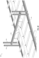
- FIG. 4 A is a close-up view of the system 100 b illustrating a second attachment equipment 110 b including a series of single-axis rail supports according to the present disclosure.
- the attachment equipment 110 b may include a first guiding rail 118 a , a second guiding rail 118 b , and a third guiding rail 118 c .
- the first guiding rail 118 a may extend vertically from the third guiding rail 118 c in a direction perpendicular to or substantially perpendicular to the third guiding rail 118 c .
- the attachment equipment 110 b may include a fastener installer, such as the flow drill fastener installer 116 , that is coupled to the first guiding rail 118 a such that a height of the fastener installer may be adjusted along a length of the first guiding rail 118 a .
- the second guiding rail 118 b may extend horizontally from the first guiding rail 118 a in a direction perpendicular to or substantially perpendicular to the first guiding rail 118 a and/or the third guiding rail 118 c .
- the fastener installer of the attachment equipment 110 b may be positioned on top of and coupled to the second guiding rail 118 b such that sliding along the length of the second guiding rail 118 b may adjust the fastener installer towards and/or away from the structural component 130 .
- the third guiding rail 118 c may extend generally horizontally with the length of the structural component 130 .
- the fastener installer of the attachment equipment 110 b may be moved along a length of structural component 130 up to approximately the length of the third guiding rail 118 c by the first guiding rail 118 a sliding along the length of the third guiding rail 118 c .
- the first guiding rail 118 a may not move along the length of the third guiding rail 118 c and the position of the structural component 130 relative to the attachment equipment 110 b may be adjusted by moving the structural component 130 .
- An automated attachment system including the attachment equipment 110 b may facilitate adjustment of the fastener installer to accommodate structural components 130 and/or mounting devices 140 of varying specifications.
- an automated attachment system may be configured to attach mounting devices of various styles to structural components of various styles.
- the position of the fastener installer may be adjusted to align with various styles of mounting devices 140 and/or structural components 130 .
- FIG. 4 B is a close-up view of the system 100 b including an octagonal torque tube 135 as the structural component 130 and a different style of module clamps 145 as the mounting device 140 . As illustrated in FIG.
- the position of the flow drill fastener installer 116 may be adjusted along the first guiding rail 118 a , the second guiding rail 118 b , and/or the third guiding rail 118 c to align with the module clamp 145 and the octagonal torque tube 135 .
- FIG. 4 C is a close-up view of a third example system 100 c illustrating a multi-axis robotic arm support 110 c according to the present disclosure.
- the multi-axis robotic arm support 110 c may increase the rotational and/or positional flexibility and adaptability of the flow drill fastener installer 116 .
- the multi-axis robotic arm support 110 c may facilitate setting more specific and/or nuanced settings for attachment of mounting devices to the structural component and/or coupling other components to the mounting devices before and/or after coupling the mounting devices to the structural component.
- one multi-axis robotic arm support 110 c may facilitate attachment of the fastener strip 150 to the structural component 130 and/or attachment of the fastener strip 150 to one or more of the mounting devices 140 in lieu of multiple pieces of attachment equipment such as the attachment equipment 110 a and/or 110 b.
- FIG. 4 D is a close-up view of a fourth example system 100 d illustrating a tri-axis rail support 110 d according to the present disclosure.
- the attachment equipment 110 b may include a first guiding rail 118 a , a second guiding rail 118 b , and a third guiding rail 118 c .
- the first guiding rail 118 a and/or the second guiding rail 118 b may be the same as or similar to the guiding rails described above in relation to FIG. 4 A .
- the third guiding rail 118 c may extend along approximately an entire length of the structural component 130 , and the attachment equipment 110 b may slide along the third guiding rail 118 c such that the attachment equipment 110 b may fasten the mounting devices 140 to the structural component 130 at any point along the length of the structural component 130 .
- the third guiding rail 118 c may be positioned in the same or a similar position as the third guiding rail 118 c as described above in relation to FIG. 4 A .
- an automated feeder such as the automated feeder 112 as described above in relation to FIG. 2 , may be used with the tri-axis rail support 110 d to provide and/or position mounting devices for attachment to the structural component.
- FIG. 5 illustrates a fifth example system 100 e of automated attachment of solar components including multiple attachment equipment stations 110 e according to the present disclosure.
- the assembly platform (not shown) of the structural component may be stationary, and multiple attachment equipment stations 110 e may be used to fasten multiple mounting devices to the structural component at the same time, in quick succession, and/or with reduced movement of the structural component.
- each of the attachment equipment stations 110 e may include the same as or similar attachment equipment as the attachment equipment 110 a as described above in relation to FIG. 1 A . Additionally or alternatively, each of the attachment equipment stations 110 e may include the same as or similar attachment equipment as any of the attachment equipment 110 b - d.
- FIG. 5 illustrates a sufficient number of the attachment equipment stations 110 e to attach all of the mounting devices to the structural component at once, in some embodiments, a smaller number of stations is also contemplated.
- the structural component may be moved into place and two or four distinct mounting devices may be attached to the structural component. The structural component may then be moved relative to the four attachment equipment stations 110 e such that the four attachment equipment stations 110 e may be positioned and ready for a next batch of mounting devices to attach to the structural component.
- FIG. 6 illustrates installation of a fastener based on a flow drill fastening (“FDF”) process 200 .
- the FDF process 200 may include positioning a fastener 210 , penetrating a sheet of metal 205 , forming threads 224 in the hole formed by the penetration, and tightening the fastener 210 .
- the fastener 210 used in the FDF process 200 may include a fastener head 212 , a flange 214 , a (partially) threaded body 216 , and a boring component 218 .
- the fastener 210 may be rotated at a high rate (e.g., 8,000 to 9,000 RPM) and pressed into the sheet of metal 205 with high force to generate localized frictional heat that facilitates penetrating the sheet of metal 205 and creating a hole 220 including a molded wall 222 and causing the metal into which the fastener 210 is being driven (e.g., the sheet of metal 205 ) to form a flowable material.
- the rotational speed of the fastener 210 may be reduced after forming the hole 220 such that the threads 224 may be formed in the molded wall 222 that forms of the flowable material.
- the fastener 210 may be tightened in the hole 220 after formation of the hole 220 and the threads 224 .
- the FDF process may include an initial, high speed period of rotation (corresponding to “2. Penetration”) followed by a second, slower speed period of rotation (corresponding to “3. Thread forming”) in which threads are formed in the sheet of metal 205 as the flowing metal resolidifies.
- the FDF process may improve attachment of the fastener 210 to a structural component (such as a torque tube) relative to other attachment processes because the FDF process may attach the fastener 210 to the structural component while only accessing one side of the structural component. As such, the FDF process does not require accessing the interior of the structural component to attach the fastener 210 to the structural component, which may simplify the attachment process. For example, attachment of the fastener 210 by the FDF process may remove the need for using a nut coupled to the fastener 210 via the interior of the structural component to secure the fastener 210 to the structural component, e.g., the fastener may couple the components without the use of a nut.
- FIGS. 1 A- 6 Modifications, additions, or omissions may be made to any of the foregoing FIGS. 1 A- 6 without departing from the scope of the present disclosure.
- the designations of different elements in the manner described is meant to help explain concepts described herein and is not limiting.
- the systems 100 a - e may include any number of other elements or may be implemented within other systems or contexts than those described.
Landscapes
- Engineering & Computer Science (AREA)
- Mechanical Engineering (AREA)
- Chemical & Material Sciences (AREA)
- Sustainable Development (AREA)
- Sustainable Energy (AREA)
- Thermal Sciences (AREA)
- Physics & Mathematics (AREA)
- Combustion & Propulsion (AREA)
- Life Sciences & Earth Sciences (AREA)
- General Engineering & Computer Science (AREA)
- Connection Of Plates (AREA)
- Roof Covering Using Slabs Or Stiff Sheets (AREA)
- Automatic Assembly (AREA)
Abstract
Description
Claims (8)
Priority Applications (2)
| Application Number | Priority Date | Filing Date | Title |
|---|---|---|---|
| US18/480,330 US12206357B2 (en) | 2021-07-13 | 2023-10-03 | Automated attachment of solar components |
| US18/981,012 US12567829B2 (en) | 2021-07-13 | 2024-12-13 | Automated attachment of solar components |
Applications Claiming Priority (3)
| Application Number | Priority Date | Filing Date | Title |
|---|---|---|---|
| US202163221348P | 2021-07-13 | 2021-07-13 | |
| US17/812,409 US11817819B2 (en) | 2021-07-13 | 2022-07-13 | Automated attachment of solar components |
| US18/480,330 US12206357B2 (en) | 2021-07-13 | 2023-10-03 | Automated attachment of solar components |
Related Parent Applications (1)
| Application Number | Title | Priority Date | Filing Date |
|---|---|---|---|
| US17/812,409 Division US11817819B2 (en) | 2021-07-13 | 2022-07-13 | Automated attachment of solar components |
Related Child Applications (1)
| Application Number | Title | Priority Date | Filing Date |
|---|---|---|---|
| US18/981,012 Continuation US12567829B2 (en) | 2021-07-13 | 2024-12-13 | Automated attachment of solar components |
Publications (2)
| Publication Number | Publication Date |
|---|---|
| US20240030861A1 US20240030861A1 (en) | 2024-01-25 |
| US12206357B2 true US12206357B2 (en) | 2025-01-21 |
Family
ID=83283145
Family Applications (3)
| Application Number | Title | Priority Date | Filing Date |
|---|---|---|---|
| US17/812,409 Active US11817819B2 (en) | 2021-07-13 | 2022-07-13 | Automated attachment of solar components |
| US18/480,330 Active US12206357B2 (en) | 2021-07-13 | 2023-10-03 | Automated attachment of solar components |
| US18/981,012 Active US12567829B2 (en) | 2021-07-13 | 2024-12-13 | Automated attachment of solar components |
Family Applications Before (1)
| Application Number | Title | Priority Date | Filing Date |
|---|---|---|---|
| US17/812,409 Active US11817819B2 (en) | 2021-07-13 | 2022-07-13 | Automated attachment of solar components |
Family Applications After (1)
| Application Number | Title | Priority Date | Filing Date |
|---|---|---|---|
| US18/981,012 Active US12567829B2 (en) | 2021-07-13 | 2024-12-13 | Automated attachment of solar components |
Country Status (3)
| Country | Link |
|---|---|
| US (3) | US11817819B2 (en) |
| AU (1) | AU2022312450B2 (en) |
| WO (1) | WO2023287923A1 (en) |
Families Citing this family (4)
| Publication number | Priority date | Publication date | Assignee | Title |
|---|---|---|---|---|
| US20240140292A1 (en) * | 2022-10-26 | 2024-05-02 | Array Tech, Inc. | Solar component storage and distribution devices |
| WO2025111182A1 (en) * | 2023-11-21 | 2025-05-30 | Nextracker Llc | In-situ solar tracker manufacturing |
| WO2025128855A1 (en) * | 2023-12-14 | 2025-06-19 | Nextracker Llc | Automated solar tracking component installation |
| CN118321907B (en) * | 2024-06-14 | 2024-10-11 | 上海博珖机器人有限公司 | Photovoltaic array semi-finished product assembling method |
Citations (8)
| Publication number | Priority date | Publication date | Assignee | Title |
|---|---|---|---|---|
| US20120027550A1 (en) | 2010-07-29 | 2012-02-02 | John Bellacicco | Automated installation system for and method of deployment of photovoltaic solar panels |
| WO2013009409A2 (en) | 2011-06-02 | 2013-01-17 | Dow Corning Corporation | Method of installing a solar module assembly |
| US20140360552A1 (en) | 2012-07-19 | 2014-12-11 | Brittmore Group LLC | Solar Panel Field Array Support System and Apparatus and Method for Construction Use |
| US9150258B1 (en) * | 2014-06-25 | 2015-10-06 | Ford Global Technologies, Llc | Vehicle body structure and method for assembling same |
| US20160065121A1 (en) | 2014-08-29 | 2016-03-03 | First Solar, Inc. | Universal cassette |
| US20160365825A1 (en) * | 2008-11-17 | 2016-12-15 | Kbfx Llc | Finished multi-sensor units |
| US20190134822A1 (en) * | 2016-03-18 | 2019-05-09 | Intelli-Products Inc. | Solar Energy Array Robotic Assembly |
| US20200350850A1 (en) | 2017-11-14 | 2020-11-05 | Comau S.P.A. | A Method and System for Installing Photovoltaic Solar Panels in an Outdoor Area |
Family Cites Families (6)
| Publication number | Priority date | Publication date | Assignee | Title |
|---|---|---|---|---|
| US11063553B2 (en) * | 2008-11-17 | 2021-07-13 | Kbfx Llc | Solar carports, solar-tracking carports, and methods |
| US8657991B2 (en) * | 2011-02-08 | 2014-02-25 | Chevron U.S.A. Inc. | Robotic solar panel string assembly process |
| US9180917B1 (en) * | 2014-09-02 | 2015-11-10 | Ford Global Technologies, Llc | Supplemental support flange for a vehicle frame pillar and expanded daylight opening of panoramic sunroof |
| CN104699360B (en) | 2015-03-30 | 2018-04-27 | 京东方科技集团股份有限公司 | A kind of electromagnetic touch formula three-dimensional grating and display device |
| US9545958B1 (en) * | 2015-09-25 | 2017-01-17 | Ford Global Technologies, Llc | Offset shear plate |
| US9868476B1 (en) * | 2016-10-05 | 2018-01-16 | Ford Global Technologies, Llc | Vehicle body-in-white structure |
-
2022
- 2022-07-13 AU AU2022312450A patent/AU2022312450B2/en active Active
- 2022-07-13 WO PCT/US2022/037020 patent/WO2023287923A1/en not_active Ceased
- 2022-07-13 US US17/812,409 patent/US11817819B2/en active Active
-
2023
- 2023-10-03 US US18/480,330 patent/US12206357B2/en active Active
-
2024
- 2024-12-13 US US18/981,012 patent/US12567829B2/en active Active
Patent Citations (8)
| Publication number | Priority date | Publication date | Assignee | Title |
|---|---|---|---|---|
| US20160365825A1 (en) * | 2008-11-17 | 2016-12-15 | Kbfx Llc | Finished multi-sensor units |
| US20120027550A1 (en) | 2010-07-29 | 2012-02-02 | John Bellacicco | Automated installation system for and method of deployment of photovoltaic solar panels |
| WO2013009409A2 (en) | 2011-06-02 | 2013-01-17 | Dow Corning Corporation | Method of installing a solar module assembly |
| US20140360552A1 (en) | 2012-07-19 | 2014-12-11 | Brittmore Group LLC | Solar Panel Field Array Support System and Apparatus and Method for Construction Use |
| US9150258B1 (en) * | 2014-06-25 | 2015-10-06 | Ford Global Technologies, Llc | Vehicle body structure and method for assembling same |
| US20160065121A1 (en) | 2014-08-29 | 2016-03-03 | First Solar, Inc. | Universal cassette |
| US20190134822A1 (en) * | 2016-03-18 | 2019-05-09 | Intelli-Products Inc. | Solar Energy Array Robotic Assembly |
| US20200350850A1 (en) | 2017-11-14 | 2020-11-05 | Comau S.P.A. | A Method and System for Installing Photovoltaic Solar Panels in an Outdoor Area |
Non-Patent Citations (1)
| Title |
|---|
| European Patent Office; International Search Report and Written Opinion in Int'l App No. PCT/US2022/037020 dated Nov. 28, 2022. |
Also Published As
| Publication number | Publication date |
|---|---|
| WO2023287923A1 (en) | 2023-01-19 |
| US12567829B2 (en) | 2026-03-03 |
| US11817819B2 (en) | 2023-11-14 |
| AU2022312450B2 (en) | 2025-07-03 |
| US20230015330A1 (en) | 2023-01-19 |
| AU2022312450A1 (en) | 2024-02-29 |
| US20240030861A1 (en) | 2024-01-25 |
| US20250119094A1 (en) | 2025-04-10 |
Similar Documents
| Publication | Publication Date | Title |
|---|---|---|
| US12206357B2 (en) | Automated attachment of solar components | |
| US8987584B2 (en) | Pre-assembled solar panel mounting system and rapid solar panel mounting system | |
| JP5457285B2 (en) | Solar panel mounting base | |
| CN204487039U (en) | Universal Tube-sheet Welding equipment | |
| US20120279069A1 (en) | Methods and equipment for constructing solar sites | |
| JPS59143780A (en) | Method of automatically installing vehicle parts and device therefor | |
| KR102641281B1 (en) | Automatic guide system for mullion connector of curtain wall for automatic piece fastening | |
| CN205743041U (en) | Bracing mounting fixture and connection structure thereof | |
| US20230174324A1 (en) | Tool for securing and turning over for assembling photovoltaic solar tracker sections, system and associated assembly method | |
| US20250373195A1 (en) | Solar module frame coupling assemblies | |
| CN118926854A (en) | Fully automatic movable photovoltaic tracking system assembly production line and assembly method | |
| CN218984719U (en) | Clamp for toilet floor processing | |
| CN106401199A (en) | Inclined strut fixing clamp, connecting structure and construction method of inclined strut fixing clamp | |
| US12539568B1 (en) | Systems and methods for installing push-in fasteners | |
| CN220427087U (en) | Rail welding clamp | |
| CN223684682U (en) | Track for welding pile extension of prefabricated pipe pile and pile extension welding device of prefabricated pipe pile | |
| CN113560791A (en) | Based on BIM assembled steel construction building steel prefab processingequipment | |
| CN221110736U (en) | Positioning tool for plate-shaped workpiece | |
| CN105499888B (en) | Suck formula positioning tool | |
| CN224183801U (en) | Plastic-aluminum board welding banding device | |
| CN219875542U (en) | Locking component and photovoltaic bracket using same | |
| CN211162672U (en) | Equipment for circumferential welding of batch parts | |
| CN223811786U (en) | Tightening equipment for screws | |
| CN217924454U (en) | Clamp for mounting color steel tile and assembly thereof | |
| CN119426657B (en) | Punching and locking mechanism and locking method for automatic laying of photovoltaic panels |
Legal Events
| Date | Code | Title | Description |
|---|---|---|---|
| AS | Assignment |
Owner name: ARRAY TECH, INC., NEW MEXICO Free format text: CHANGE OF NAME;ASSIGNOR:ARRAY TECHNOLOGIES, INC.;REEL/FRAME:065115/0197 Effective date: 20201028 Owner name: ARRAY TECHNOLOGIES, INC., NEW MEXICO Free format text: ASSIGNMENT OF ASSIGNORS INTEREST;ASSIGNORS:SCHUKNECHT, NATHAN;CREASY, LUCAS;SIGNING DATES FROM 20210726 TO 20210817;REEL/FRAME:065111/0417 |
|
| FEPP | Fee payment procedure |
Free format text: ENTITY STATUS SET TO UNDISCOUNTED (ORIGINAL EVENT CODE: BIG.); ENTITY STATUS OF PATENT OWNER: LARGE ENTITY |
|
| STPP | Information on status: patent application and granting procedure in general |
Free format text: DOCKETED NEW CASE - READY FOR EXAMINATION |
|
| STPP | Information on status: patent application and granting procedure in general |
Free format text: NON FINAL ACTION MAILED |
|
| STPP | Information on status: patent application and granting procedure in general |
Free format text: RESPONSE TO NON-FINAL OFFICE ACTION ENTERED AND FORWARDED TO EXAMINER |
|
| STPP | Information on status: patent application and granting procedure in general |
Free format text: NOTICE OF ALLOWANCE MAILED -- APPLICATION RECEIVED IN OFFICE OF PUBLICATIONS |
|
| ZAAB | Notice of allowance mailed |
Free format text: ORIGINAL CODE: MN/=. |
|
| STPP | Information on status: patent application and granting procedure in general |
Free format text: AWAITING TC RESP., ISSUE FEE NOT PAID |
|
| STPP | Information on status: patent application and granting procedure in general |
Free format text: NOTICE OF ALLOWANCE MAILED -- APPLICATION RECEIVED IN OFFICE OF PUBLICATIONS |
|
| STPP | Information on status: patent application and granting procedure in general |
Free format text: PUBLICATIONS -- ISSUE FEE PAYMENT VERIFIED |
|
| STCF | Information on status: patent grant |
Free format text: PATENTED CASE |
|
| AS | Assignment |
Owner name: GOLDMAN SACHS BANK USA, AS COLLATERAL AGENT, NEW YORK Free format text: SUPPLEMENT NO. 1 TO PATENT SECURITY AGREEMENT;ASSIGNOR:ARRAY TECH, INC.;REEL/FRAME:071149/0854 Effective date: 20250501 |