US12206262B2 - Pulse width communication in a wireless power system - Google Patents
Pulse width communication in a wireless power system Download PDFInfo
- Publication number
- US12206262B2 US12206262B2 US18/256,539 US202118256539A US12206262B2 US 12206262 B2 US12206262 B2 US 12206262B2 US 202118256539 A US202118256539 A US 202118256539A US 12206262 B2 US12206262 B2 US 12206262B2
- Authority
- US
- United States
- Prior art keywords
- wireless power
- pulse
- reception apparatus
- power transmission
- pulse width
- Prior art date
- Legal status (The legal status is an assumption and is not a legal conclusion. Google has not performed a legal analysis and makes no representation as to the accuracy of the status listed.)
- Active
Links
Images


Classifications
-
- H—ELECTRICITY
- H02—GENERATION; CONVERSION OR DISTRIBUTION OF ELECTRIC POWER
- H02J—ELECTRIC POWER NETWORKS; CIRCUIT ARRANGEMENTS OR SYSTEMS FOR SUPPLYING OR DISTRIBUTING ELECTRIC POWER; SYSTEMS FOR STORING ELECTRIC ENERGY
- H02J50/00—Circuit arrangements or systems for wireless supply or distribution of electric power
- H02J50/80—Circuit arrangements or systems for wireless supply or distribution of electric power involving the exchange of data, concerning supply or distribution of electric power, between transmitting devices and receiving devices
-
- H—ELECTRICITY
- H02—GENERATION; CONVERSION OR DISTRIBUTION OF ELECTRIC POWER
- H02J—ELECTRIC POWER NETWORKS; CIRCUIT ARRANGEMENTS OR SYSTEMS FOR SUPPLYING OR DISTRIBUTING ELECTRIC POWER; SYSTEMS FOR STORING ELECTRIC ENERGY
- H02J50/00—Circuit arrangements or systems for wireless supply or distribution of electric power
- H02J50/10—Circuit arrangements or systems for wireless supply or distribution of electric power using inductive coupling
-
- H—ELECTRICITY
- H02—GENERATION; CONVERSION OR DISTRIBUTION OF ELECTRIC POWER
- H02J—ELECTRIC POWER NETWORKS; CIRCUIT ARRANGEMENTS OR SYSTEMS FOR SUPPLYING OR DISTRIBUTING ELECTRIC POWER; SYSTEMS FOR STORING ELECTRIC ENERGY
- H02J50/00—Circuit arrangements or systems for wireless supply or distribution of electric power
- H02J50/60—Circuit arrangements or systems for wireless supply or distribution of electric power responsive to the presence of foreign objects, e.g. detection of living beings
-
- H—ELECTRICITY
- H02—GENERATION; CONVERSION OR DISTRIBUTION OF ELECTRIC POWER
- H02J—ELECTRIC POWER NETWORKS; CIRCUIT ARRANGEMENTS OR SYSTEMS FOR SUPPLYING OR DISTRIBUTING ELECTRIC POWER; SYSTEMS FOR STORING ELECTRIC ENERGY
- H02J50/00—Circuit arrangements or systems for wireless supply or distribution of electric power
- H02J50/90—Circuit arrangements or systems for wireless supply or distribution of electric power involving detection or optimisation of position, e.g. alignment
-
- H—ELECTRICITY
- H04—ELECTRIC COMMUNICATION TECHNIQUE
- H04L—TRANSMISSION OF DIGITAL INFORMATION, e.g. TELEGRAPHIC COMMUNICATION
- H04L25/00—Baseband systems
- H04L25/38—Synchronous or start-stop systems, e.g. for Baudot code
- H04L25/40—Transmitting circuits; Receiving circuits
- H04L25/49—Transmitting circuits; Receiving circuits using code conversion at the transmitter; using predistortion; using insertion of idle bits for obtaining a desired frequency spectrum; using three or more amplitude levels ; Baseband coding techniques specific to data transmission systems
- H04L25/4902—Pulse width modulation; Pulse position modulation
Definitions
- This disclosure relates generally to wireless power. More specifically, this application relates to communication between a wireless power reception apparatus and a wireless power transmission apparatus.
- Wireless power technology has been developed to enable the wireless transmission of power from a wireless power transmission apparatus to a wireless power reception apparatus.
- a wireless power reception apparatus may include a mobile device, a small electronic device, a computer, a tablet, a gadget, an appliance (including some types of cordless blenders, kettles, mixers, etc.), and some types of larger electronic devices, among other examples.
- a wireless power transmission apparatus may include a primary coil that produces an electromagnetic field. The electromagnetic field may induce a voltage in a secondary coil of a wireless power reception apparatus when the secondary coil is placed in proximity to the primary coil. In this configuration, the electromagnetic field may wirelessly transfer power to the secondary coil. The power may be transferred using inductive coupling or resonant coupling between the primary coil and the secondary coil.
- Wireless power transmission may also be referred to as a contactless power transmission or a non-contact power transmission.
- a wireless power transmission apparatus When performing a wireless power transmission, a wireless power transmission apparatus should stop the power transmission when a wireless power reception apparatus is removed from a charging area.
- a wireless power transmission apparatus may detect the presence of the wireless power reception apparatus during the transmission of power and enable changes to an operating point of a wireless power signal based on a control signal such as a control error packet. For example, a wireless power transmission apparatus may detect that a wireless power reception apparatus has been removed from the charging area when the control error packet is not received for a predetermined period (such as, 1.8 seconds).
- the control error packet may include information that causes a wireless power transmission apparatus to modify an amount of power, current, voltage, or another parameter.
- a wireless power transmission apparatus may communicate information to a wireless power reception apparatus relevant to the wireless power transmission.
- Existing techniques for communication between a wireless power reception apparatus and a wireless power transmission apparatus may benefit from improvements.
- the method may be performed by a wireless power transmission apparatus.
- the method may include transmitting wireless power to a wireless power reception apparatus via at least one primary coil.
- the method may include receiving a pulse width modulation (PWM) signal from the wireless power reception apparatus.
- the PWM signal may include one or more pulses.
- the method may include determining a feedback parameter based on a pulse width of the one or more pulses.
- the method may include managing a transmission of the wireless power from the wireless power transmission apparatus to the wireless power reception apparatus based, at least in part, on the feedback parameter.
- PWM pulse width modulation
- the feedback parameter is a control error value.
- Managing the transmission of the wireless power may include setting an operating point for the transmission of the wireless power based, at least in part, on the control error value.
- the feedback parameters indicate a load power.
- Managing the transmission of the wireless power includes determining whether a foreign object is detected based on a comparison of the load power and a transmitted amount of the wireless power.
- determining the feedback parameter includes determining a pulse width ratio based on the pulse width of the one or more pulses and converting the pulse width ratio to the feedback parameter based on a predetermined translation.
- receiving the PWM signal includes receiving a plurality of pulses occupying respective pulse time slots.
- a duration of each pulse time slots is 0.5 milliseconds such that the pulse time slots are equivalent to a 2 kHz communication clock cycle.
- the PWM signal includes a pulse in every other pulse time slot.
- the one or more pulses includes at least a first pulse and a second pulse.
- a pulse width of the first pulse may indicate a sign of the feedback parameter.
- a pulse width of the second pulse may indicate a magnitude of the feedback parameter.
- the method may include, before receiving the PWM signal, receiving a start analog control packet that indicates the PWM signal will follow the start analog control packet.
- the method may include receiving the start analog control packet encoded as a differential bi-phase encoded signal.
- the method may include receiving a series of sequential pulses that correspond to a predetermined pattern of pulse widths and determining that the series of sequential pulses indicates an end of the PWM signal.
- the method may include, after the end of the PWM signal, receiving an end analog control packet or other packet encoded as a differential bi-phase encoded signal.
- receiving the PWM signal includes receiving the PWM signal via the primary coil.
- receiving the PWM signal includes receiving the PWM signal via a wireless communication interface that is separate from the primary coil.
- the wireless communication interface is a short-range radio frequency interface or a near field communication interface.
- receiving the PWM signal includes detecting a load variation during the transmission of the wireless power.
- receiving the PWM signal includes activating a PWM communication technique for analog control based on the feedback parameter.
- the method may include activating the PWM communication technique includes sending a first packet to the wireless power reception apparatus indicating that the wireless power transmission apparatus supports the PWM communication technique.
- the method may include receiving a second packet from the wireless power reception apparatus indicating that the wireless power reception apparatus is activating the PWM communication technique.
- the method may be performed by a wireless power reception apparatus.
- the method may include receiving wireless power from a wireless power transmission apparatus via at least one secondary coil of the wireless power reception apparatus.
- the method may include determining a feedback parameter based on the wireless power, the feedback parameter for the wireless power transmission apparatus to manage a transmission of the wireless power.
- the method may include communicating a pulse width modulation (PWM) signal from the wireless power reception apparatus to the wireless power transmission apparatus.
- PWM signal may include one or more pulses. Each pulse may have a pulse width based, at least in part, on the feedback parameter.
- the method may include, after communicating the PWM signal, receiving wireless power.
- An operating point of the wireless power transmission apparatus may be adjusted based on the feedback parameter.
- the feedback parameter is a control error value based on a comparison of a desired control point and an actual control point.
- communicating the PWM signal includes performing load modulation of the wireless power using a communication unit of the wireless power reception apparatus.
- the load modulation may be based on the pulse width of each pulse.
- communicating the PWM signal includes performing a communication modulation using a wireless communication interface that is separate from the at least one secondary coil of the wireless power reception apparatus.
- the communication modulation may cause a received communication signal or a transmitted communication signal to have the one or more pulses.
- the method may include transmitting the PWM signal includes periodically determining a new feedback parameter and periodically communicating a new pulse to the wireless power transmission apparatus.
- Each new pulse may have a corresponding pulse width based on the new feedback parameter.
- transmitting the PWM signal includes converting the feedback parameter to pulse width ratio based on a predetermined translation and determining the pulse width of the one or more pulses based on the pulse width ratio.
- communicating the PWM signal includes communicating a plurality of pulses, each pulse occupying a respective pulse time slot.
- a duration of each pulse time slot may be 0.5 milliseconds such that that the pulse time slots are equivalent to a 2 kHz communication clock cycle.
- the PWM signal includes a pulse in every other pulse time slot.
- the method may include, before communicating the PWM signal, communicating a start analog control packet that indicates the PWM signal will follow the start analog control packet.
- the method may include communicating the start analog control packet as a differential bi-phase encoded signal.
- the method may include communicating a series of sequential pulses that correspond to a predetermined pattern of pulse widths.
- the series of sequential pulses may indicate an end of the PWM signal.
- the method may include, after the end of the PWM signal, communicating an end analog control packet or other packet encoded as a differential bi-phase encoded signal.
- communicating the PWM signal includes communicating the PWM signal via the secondary coil.
- communicating the PWM signal includes communicating the PWM signal via a wireless communication interface that is separate from the secondary coil.
- the wireless communication interface is a short-range radio frequency interface or a near field communication interface.
- the method may include, before communicating the PWM signal, activating a PWM communication technique for analog control based on the feedback parameter.
- activating the PWM communication technique includes receiving a first packet from the wireless power transmission apparatus indicating that the wireless power transmission apparatus supports the PWM communication technique.
- the method may include communicating a second packet to the wireless power transmission apparatus indicating that the wireless power reception apparatus is activating the PWM communication technique.
- the method may be performed by a wireless power transmission apparatus.
- the method may include transmitting wireless power to a wireless power reception apparatus via at least one primary coil.
- the method may include determining a message value to communicate to the wireless power reception apparatus.
- the method may include determining a pulse width of one or more pulses of a pulse width modulation (PWM) signal based, at least in part, on the message value.
- PWM pulse width modulation
- the method may include transmitting a frequency modulated signal from the wireless power transmission apparatus to the wireless power reception apparatus based on the pulse width, whereas the frequency modulated signal has a first frequency during an on-time duration of the pulse width.
- the frequency modulated signal may have a second frequency during times other than the on-time duration of the pulse width.
- the message value is an acknowledgement (ACK), non-acknowledgement (NAK), or a non-defined (ND) response.
- ACK acknowledgement
- NAK non-acknowledgement
- ND non-defined response
- the pulse width may have a first duration when the message value is the ACK.
- the pulse width may have a second duration when the message value is the NAK.
- the pulse width may have a third duration when the message value is the ND response.
- the first duration, the second duration, and the third duration are within different ranges defined by a standard technical specification.
- the method may be performed by a wireless power reception apparatus.
- the method may include receiving wireless power from a wireless power transmission apparatus via at least one secondary coil of the wireless power reception apparatus.
- the method may include receiving a frequency modulated signal from the wireless power transmission apparatus, the frequency modulated signal having one or more pulses according to a PWM signal.
- the method may include determining a pulse width of one or more pulses based, at least in part, a first frequency of the frequency modulated signal.
- the frequency modulated signal may have the first frequency during an on-time duration of the pulse width.
- the frequency modulated signal may have a second frequency during times other than the on-time duration of the pulse width.
- the method may include determining a message value based, at least in part, on the pulse width.
- the wireless power transmission apparatus may have a power transfer coil, a communication unit, and a control unit.
- the power transfer coil, the communication unit, and the control unit may be configured to perform any one of the above-mentioned methods.
- the wireless power reception apparatus may have a power transfer coil, a communication unit, and a control unit.
- the power transfer coil, the communication unit, and the control unit may be configured to perform any one of the above-mentioned methods.
- Another innovative aspect of the subject matter described in this disclosure can be implemented as a computer-readable medium having stored therein instructions which, when executed by a processor, causes the processor to perform any one of the above-mentioned methods.
- FIG. 1 shows a block diagram of an example wireless power system that includes an example wireless power transmission apparatus and an example wireless power reception apparatus.
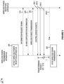
- FIG. 2 shows a message flow diagram of an example wireless power transmission process.
- FIG. 3 shows an example of a power control process performed between a wireless power transmission device and a wireless power reception apparatus.
- FIG. 4 shows a block diagram conceptually illustrating an example control error packet.
- FIG. 5 shows a block diagram conceptually illustrating byte encoding.
- FIG. 6 shows a block diagram conceptually illustrating an example wireless power reception apparatus.
- FIG. 7 shows a signal diagram conceptually illustrating a differential bi-phase encoding technique for communicating a digital signal.
- FIG. 8 shows a timing diagram conceptually illustrating a plurality of control error packets.
- FIG. 9 shows a signal diagram conceptually illustrating an example pulse width modulation (PWM) communication technique.
- PWM pulse width modulation
- FIG. 10 shows an example relationship between a control error value and a pulse width ratio.
- FIG. 11 A shows example calculations for determining a pulse width to represent a control error value.
- FIG. 11 B shows example calculations for determining a control error value based on a pulse.
- FIG. 12 A shows a timing diagram conceptually illustrating signaling for a plurality of pulses.
- FIG. 12 B shows another timing diagram conceptually illustrating signaling for a plurality of pulses in which a pulse occurs in every other pulse time slot.
- FIG. 12 C shows another timing diagram conceptually illustrating signaling for a plurality of pulses in which a feedback parameter can be encoded in two pulses.
- FIG. 13 shows a timing diagram conceptually illustrating signaling for activating or deactivating a PWM communication technique.
- FIG. 14 shows a block diagram conceptually illustrating an example wireless power reception apparatus capable of using a PWM communication technique via an out-of-band communication channel.
- FIG. 15 shows a flow diagram illustrating example operations of a process using a PWM communication technique in a wireless power transmission apparatus.
- FIG. 18 shows a flow diagram illustrating example operations of another process using a PWM communication technique in a wireless power transmission apparatus.
- the wireless power transmission apparatus may periodically check whether the CEP is received within a predetermined period and may control or stop the transmission of wireless power based on the CEP.
- Traditional techniques for CEP have been useful for low power or slower wireless power systems. However, as wireless power systems seek to increase power levels and decrease time between adjustments, the traditional techniques for CEP may be inadequate due to delay or communication inefficiency.
- some examples of this disclosure describe communication of a control error value that would otherwise be communicated in a CEP. While the examples in this disclosure relate to a control signal for a control error value transmitted from the wireless power reception apparatus to the wireless power transmission apparatus, the communication techniques in this disclosure can be used for other types of control or feedback information from the wireless power reception apparatus to the wireless power transmission apparatus. Furthermore, in some implementations, the communication techniques may be used for feedforward information from the wireless power transmission apparatus to the wireless power reception apparatus.
- a wireless power reception apparatus may communicate the feedback parameter to indicate an ongoing presence of the wireless power reception apparatus or to cause a wireless power transmission apparatus to adjust its operating point for the transmission of wireless power.
- the feedback parameter may be a control error value.
- the control error value may be communicated more efficiently using an analog representation.
- a pulse width modulation (PWM) communication technique may include a variable sized pulse width to represent and communicate a feedback parameter. For example, a pulse width size may indicate a magnitude or other information about the feedback parameter.
- a PWM communication technique may vary a pulse width of a single pulse within a predetermined pulse time slot.
- Each pulse may have an “on-time” duration during the pulse time slot, where the on-time duration is distinct from an “off-time” during the pulse time slot.
- the on-time of a pulse may have a predetermined amplitude or predetermined signal frequency to distinguish it from the off-time.
- a pulse width (also referred to as a pulse duration, a pulse length, or a pulse size) may refer to the on-time duration of the pulse within the pulse time slot.
- a pulse width ratio is a numerical representation that refers to a proportion of the pulse width (on-time duration of the pulse) to the duration of the pulse time slot.
- a pulse width ratio also may be referred to as a duty cycle or duty ratio associated with a single pulse within a pulse time slot.
- a PWM signal (also referred to as a pulse train) can include a plurality of pulses.
- the pulse width ratio associated with a single pulse may indicate the control error value.
- a PWM signal may include a plurality of pulses and the pulse width ratio associated with each pulse may communicate a control error value. Therefore, changes to the control error value may be communicated frequently and quickly, enabling the wireless power transmission system to adapt to changes in the environment or power requirements.
- a traditional communication technique may use amplitude shift key (ASK) modulation or frequency shift key (FSK) modulation to communicate digital information.
- a traditional wireless power transmission system may encode the digital information for ASK or FSK transmission.
- a traditional wireless power reception apparatus may encode a control error value in a CEP for ASK transmission.
- the CEP may include at least 44 bits of digital information for a single control error value.
- the ASK transmission may be signaled according to a 2 kilohertz (kHz) frequency.
- kHz 2 kilohertz
- each bit of digital information may take 0.5 milliseconds (ms) to communicate using traditional communication technique based on ASK modulation.
- a wireless power transmission system would require at least 22 ms (44 bits ⁇ 0.5 ms/bit) to communicate a single control error value.
- the PWM communication technique of this disclosure may communicate a control error value as a variable-sized pulse that occurs during a single pulse time slot of 0.5 ms.
- the pulse time slot of 0.5 ms may align with a 2 kHz frequency that would otherwise be used for the traditional communication technique.
- the variable-sized pulse width of a pulse within a pulse time slot can convey a full analog value rather than a single bit of information using the traditional communication technique.
- the PWM communication technique may be referred to as an analog control feedback (or analog control).
- the analog control feedback may approximate a speed of a wired control line due to the efficiency of PWM to communicate a control error value or other feedback parameter.
- a communication protocol between the wireless power reception apparatus and the wireless power transmission apparatus may be adapted to support dynamic enablement or disablement of analog control.
- a start analog control packet may be signaled using traditional ASK or FSK modulation.
- the start analog control packet may signal enablement of the PWM communication technique to communicate analog control information.
- the analog control information may be communicating using the PWM communication technique in lieu of ASK or FSK modulation.
- a predetermined pattern of PWM signaling may indicate an end of the analog control so that both the wireless power reception apparatus and the wireless power transmission apparatus can return to traditional ASK or FSK modulation for digital communication.
- the PWM communication technique may be implemented using existing hardware in a traditional wireless power reception apparatus or a traditional wireless power transmission apparatus.
- a communication unit of the wireless power reception apparatus may have modulation switches capable of implementing ASK based on a switch control line from a controller.
- the controller may control one or more of the modulation switches according to a desired pulse width within a pulse time slot.
- the PWM communication technique may be implemented with minor changes to existing systems.
- the pulse widths of various pulses in a PWM signal can indicate different components or values of a feedback parameter. For example, some pulses (have a selected one of a plurality of predefined pulse widths) may indicate a positive or negative sign of a control error value. Other pulses (having a variable pulse width) may indicate the magnitude of the control error value.
- each pulse within a set of pulse time slots may indicate a different analog component of a feedback parameter. For example, a first pulse may indicate a coarse value and a second pulse may indicate a fine value. Additionally, or alternatively, each pulse within a set of consecutive pulses may indicate an offset value for fine grain adjustments to a value communicated one or more previous pulses within the set of consecutive pulses.
- the control error value may be used for control signaling and the wireless power transmission apparatus may set an operating point based on the control signaling.
- other types of feedback parameters also may be communicated for different use cases.
- FOD foreign object detection
- the feedback parameter may be a load power, rectified voltage level, quality factor, quality measurement, or some indicator related to the wireless power transfer efficiency.
- a wireless power transmission apparatus may use the feedback parameter to determine an alignment of the power transfer coils or to detect if a foreign object is in the vicinity of the power transfer coils.
- the wireless power transmission apparatus may compare the feedback parameter with an amount of wireless power transmitted during a ping signal or starting wireless power signal to determine the wireless power transfer efficiency. If the wireless power transfer efficiency is below a threshold, the wireless power transmission apparatus may determine that a foreign object is detected.
- the PWM communication technique of this disclosure can convey a control error value (or other feedback parameter) in analog form to enable a much faster communication of control error values compared to traditional communication techniques.
- the efficient communication of control information enables a better user experience and faster control of wireless power transmission systems.
- the communication techniques in this disclosure may eliminate or reduce packet or bit-encoding overhead associated with a traditional communication technique.
- the PWM communication technique may avoid or reduce delays associated with traditional feedback mechanisms.
- These techniques also may increase responsiveness to changes in load or positioning of a wireless power reception apparatus.
- the use of an efficient communication technique (such as those described herein) may prevent faults, overheating, or degradation of charging that would otherwise occur with a traditional communication technique.
- FIG. 1 shows a block diagram of an example wireless power system 100 that includes an example wireless power transmission apparatus 102 and an example wireless power reception apparatus 118 .
- the wireless power transmission apparatus includes a primary coil 104 .
- the primary coil 104 may be associated with a power signal generator 106 .
- the primary coil 104 may be a wire coil which transmits wireless power (which also may be referred to as wireless energy).
- the primary coil 104 may transmit wireless energy using inductive or magnetic resonant field.
- the power signal generator 106 may include components (not shown) to provide power to the primary coil 104 causing the primary coil 104 to produce the wireless power signal.
- the power signal generator 106 may include one or more switches, drivers, series capacitors, rectifiers or other components.
- the wireless power transmission apparatus 102 also may include a transmission controller 108 that controls the components of the power signal generator 106 .
- the transmission controller 108 may determine an operating point (such as voltage or current) and control the power signal generator 106 according to the operating point.
- the power signal generator 106 , the transmission controller 108 and other components may be collectively referred to as a power transmitter circuit 110 .
- Some or all of the power transmitter circuit 110 may be embodied as an integrated circuit (IC) that implements features of this disclosure for controlling and transmitting wireless power to one or more wireless power reception apparatuses.
- the transmission controller 108 may be implemented as a microcontroller, dedicated processor, integrated circuit, application specific integrated circuit (ASIC) or any other suitable electronic device.
- a power source 112 may provide power to the power transmitter circuit 110 in the wireless power transmission apparatus 102 .
- the power source 112 may convert alternating current (AC) power to direct current (DC) power.
- the power source 112 may include a converter that receives an AC power from an external power supply and converts the AC power to a DC power used by the power signal generator 106 .
- a first communication unit 142 may be coupled to the components of the power signal generator 106 or the primary coil 104 to send or receive communications via the wireless power signal.
- the first communication unit 142 may include logic for controlling one or more switches and other components that cause transmission and reception of wireless signals via the wireless power signal.
- the first communication unit 142 may include modulators or demodulators that convert information to ASK or FSK modulated signals.
- the first communication unit 142 may convert data from the transmission controller 108 into an FSK modulated signal that is combined with the wireless power signal for a communication from the wireless power transmission apparatus 102 to the wireless power reception apparatus 118 .
- the first communication unit 142 may sense load modulated ASK signals from the power signal generator 106 or the primary coil 104 and demodulate the ASK signals to obtain data that the first communication unit 142 provides to the transmission controller 108 .
- the wireless power transmission apparatus 102 may include a wireless communication interface 114 .
- the wireless communication interface 114 may be connected to a first communication coil 116 (which may be a coil or a loop antenna).
- the wireless communication interface 114 may include logic for controlling one or more switches and other components that cause transmission and reception of wireless communication signals via the first communication coil 116 .
- the wireless communication interface 114 may support short range radio frequency communication (such as Bluetooth) or Near-Field Communication (NFC). NFC is a technology by which data transfer occurs on a carrier frequency of 13.56 MHz.
- the wireless communication unit 124 also may support any suitable communication protocol.
- the transmission controller 108 may detect the presence or proximity of a wireless power reception apparatus 118 .
- the presence or proximity of the wireless power reception apparatus 118 may be detected based on a load change in response to a periodic low power signal generated by the power signal generator 106 and the primary coil 104 .
- the presence or proximity of the wireless power reception apparatus 118 may happen during a periodic pinging process of the wireless communication interface 114 in the wireless power transmission apparatus 102 .
- the transmission controller 108 may receive a signal strength packet from the wireless power reception apparatus 118 .
- the signal strength packet may indicate a rectified value of the received voltage.
- the transmission controller 108 may use this voltage value to check the quality of coupling between the transmitter coil and receiver coil and determine whether or not to continue providing power.
- the transmission controller 108 may control characteristics of wireless power that the wireless power transmission apparatus 102 provides to the wireless power reception apparatus 118 . After detecting the wireless power reception apparatus 118 , the transmission controller 108 may receive information from a wireless power reception apparatus 118 . For example, the transmission controller 108 may receive the information during a hand shaking process with the wireless power reception apparatus 118 . The information may include information about the wireless power reception apparatus 118 (such as a power rating, the manufacturer, and model, among other examples). The transmission controller 108 may use this information to determine at least one operating control parameter (such as frequency, duty cycle, voltage, etc.) for wireless power it provides to the wireless power reception apparatus 118 . To configure the wireless power, the transmission controller 108 may modify the frequency, duty cycle, voltage or any other suitable characteristic of the power signal generator 106 .
- the transmission controller 108 may modify the frequency, duty cycle, voltage or any other suitable characteristic of the power signal generator 106 .
- the wireless power reception apparatus 118 may include a secondary coil 120 , a rectifier 126 , and a receiver controller 128 .
- the secondary coil 120 When the secondary coil 120 is aligned to the primary coil 104 , the secondary coil 120 may generate an induced voltage based on a received wireless power signal from the primary coil 104 .
- a capacitor may be in series between the secondary coil 120 and the rectifier 126 .
- the rectifier 126 may rectify the induced voltage and provide the induced voltage to a load 130 .
- the load 130 may be external to the wireless power reception apparatus 118 and coupled via electrical lines from the rectifier 126 .
- Some implementations may include a series switch (not shown in FIG. 1 ) between the rectifier 126 and the load 130 that is capable of decoupling the load 130 from the rectifier 126 .
- a receiver controller 128 may be connected to the rectifier 126 and a second communication unit 152 .
- the second communication unit 152 may be coupled to the components of the secondary coil 120 or the rectifier 126 to send or receive communications via the wireless power signal.
- the second communication unit 152 may include logic for controlling one or more switches and other components that cause transmission and reception of communication signals via the wireless power signals.
- the second communication unit 152 may include modulators or demodulators that convert information to ASK or FSK modulated signals.
- the second communication unit 152 may convert data from the receiver controller 128 into an ASK modulated signal that used to load modulate the wireless power signal for a communication from the wireless power reception apparatus 118 to the wireless power transmission apparatus 102 .
- the second communication unit 152 may sense FSK signals in the wireless power signal at the secondary coil 120 or the rectifier 126 and demodulate the FSK signals to obtain data that the second communication unit 152 provides to the receiver controller 128 .
- the wireless power reception apparatus 118 may include a wireless communication interface 132 .
- the wireless communication interface 132 may contain modulation and demodulation circuits to wirelessly communicate via a second communication coil 134 (which may be a coil or a loop antenna).
- the receiver controller 128 may wirelessly communicate with the transmission controller 108 via the wireless communication interface 132 and the wireless communication interface 114 using NFC communications.
- the receiver controller 128 and the transmission controller 108 use communication to form a feedback control loop (such as, for example, the power control process 300 described with reference to FIG. 3 ).
- the receiver controller 128 may provide feedback to the transmission controller 108 (via any of the communication paths described herein) and the transmission controller 108 may adjust an operating point for the wireless power signal based on the feedback.
- a primary coil can transfer wireless energy to a secondary coil up to a rating predetermined by a wireless standard.
- a low power wireless power signal may convey 5 Watts (5 W), 9 W, 12 W, or 15 W.
- a low power wireless power system may deliver up to 15 Watts of energy which is suitable for many electronic devices.
- Higher power wireless systems are being developed to support wireless power transmission to electronic devices that require more power.
- medium wireless power systems and high wireless power systems may deliver greater than 15 W of wireless power.
- the wireless power systems may benefit from improved communication and control as the power ratings of wireless power transfer systems continue to increase.
- FIG. 2 shows a message flow diagram of an example wireless power transmission process.
- a wireless power transmission apparatus detects that a wireless power reception apparatus is located in a charging area in a standby mode (S 200 ).
- the wireless power transmission apparatus may detect that the wireless power reception apparatus is located in a charging area by periodically emitting analog ping of a specific frequency, and based on detection current for this, resonance shift or capacitance change.
- the wireless power transmission apparatus may periodically transmit a detection signal and the wireless power reception apparatus may transmit a response signal (for example, a control error packet or a signal strength packet).
- the wireless power transmission apparatus may detect that the wireless power reception apparatus is located in the charging area based on receiving the response signal within a predetermined time period following the detection signal.
- the wireless power reception apparatus may transmit a searching signal or an advertisement signal to the wireless power transmission apparatus.
- the searching signal or the advertisement signal may traditionally be transmitted using short range radio frequency communication (such as BluetoothTM).
- the wireless power transmission apparatus may detect the wireless power reception apparatus based on reception of the searching signal or the advertisement signal.
- the wireless power transmission apparatus may optionally transmit an information request signal to the wireless power reception apparatus (S 210 ).
- the information request signal may be a signal for requesting an ID and requesting power information of the wireless power reception apparatus.
- the information request signal may be transmitted in a form of data packet message.
- the information request signal may be transmitted in a form of digital ping according to a predefined standard between the wireless power transmission apparatus and the wireless power reception apparatus.
- the wireless power reception apparatus may optionally transmit the ID and configuration information to the wireless power transmission apparatus (S 220 ).
- the configuration information may include a requested amount of power or a maximum amount of power that is provided for the wireless power reception apparatus.
- the information request signal and the ID and configuration information may be communicated using out-of-band communication (separate from the wireless power signal) such as NFC or Bluetooth.
- the wireless power transmission apparatus configures parameters (referred to as an operating point) for power transmission and performs a wireless power transmission to the wireless power reception apparatus (S 230 ).
- the wireless power transmission apparatus may create a power transmission contract based on the ID and the configuration information and may control the wireless power transmission according to the power transmission contract.
- the process, performed by the wireless power transmission apparatus, from the start to the end of the wireless power transmission to the wireless power reception apparatus may be called a (wireless) power transfer phase.
- the wireless power reception apparatus may provide the received wireless power to an external load such as a battery.
- the wireless power transmission apparatus may monitor the parameters for power transmission and may abort the wireless power transmission when any one of the parameters exceeds a stated limit.
- the wireless power transmission process of S 230 may be ended by a request of the wireless power reception apparatus.
- the wireless power reception apparatus may transmit a signal for requesting termination of the wireless power transmission to the wireless power transmission apparatus, when a battery is fully charged.
- the wireless power reception apparatus continuously transmits a control error packet (CEP) periodically or aperiodically to the wireless power transmission apparatus (S 240 - 1 , S 240 - 2 and S 240 - 3 ). This is performed for controlling an amount of power which is transmitted from the wireless power transmission apparatus to the wireless power reception apparatus, that is, to perform a power control.
- CEP control error packet
- the power control processes like steps S 240 - 1 to S 240 - 3 may include the power control process according to the embodiments of FIG. 3 .
- FIG. 2 also illustrates the case that a control error packet is not received within a predetermined period T (such as, 1.8 sec) after the previous control error packet.
- the expected (but not received) control error packet is shown as S 240 - 4 .
- the wireless power transmission apparatus may determine that the wireless power reception apparatus is removed from the charging area, and stops the wireless power transmission (S 250 ).
- the wireless power transmission apparatus may be required to stop the wireless power transmission in the case that a user removes the wireless power reception apparatus from the charging area.
- the wireless power transmission apparatus may stop the wireless power transmission when the wireless power reception apparatus indicates a battery fully charged state.
- Another problem may occur as a result of a distortion or out-of-range parameters in a control error packet or other feedback parameter.
- a load fluctuation may cause the charge currents to be irregularly changed.
- load modulation is used to communicate the packet, the load fluctuation may cause the packet to become distorted.
- the wireless power transmission apparatus may drop the incorrect packets and, in some cases, may terminate the power transmission to the wireless power reception apparatus. This may cause unnecessary delays in control that may also lead to interruption of the wireless power transmission or delays in a battery charging.
- FIG. 3 shows an example of a power control process 300 performed between a wireless power transmission apparatus 102 and a wireless power reception apparatus 118 .
- the wireless power reception apparatus 118 selects a desired control point (S 300 ).
- the control point may include current and/or voltage, a temperature of a part of the wireless power reception apparatus, and so on.
- the wireless power reception apparatus 118 determines an actual control point based on the wireless power transmission 380 received by the power pickup unit 305 from a power conversion unit 370 of the wireless power transmission apparatus 102 (S 310 ).
- the wireless power reception apparatus 118 calculates a control error value using the desired control point and the actual control point (S 320 ). For example, the wireless power reception apparatus 118 may calculate the control error value through the (relative) difference between a desired voltage (or current) and an actual voltage (or current). The wireless power reception apparatus 118 generates control signaling based on the control error value and transmits this to the wireless power transmission apparatus (S 330 ).
- the control signaling 330 may be encoded in a control error packet. As described further in this disclosure, the control signaling 330 may be communicated as a PWM signal.
- the wireless power transmission apparatus 102 may receive the control signaling 330 and set a new operating point based on the control error value, if it is required (S 360 ).
- the operating point may be at least one of amplitude, a frequency and a duty cycle of an AC voltage applied to a primary coil.
- the wireless power transmission apparatus 102 may determine a new primary cell current (S 340 ).
- the new primary cell current may be based on an actual primary cell current (S 375 ) and the control signaling 330 .
- the wireless power transmission apparatus 102 may determine a control towards the new primary cell current (S 350 ) and determine the new operating point (S 360 ) to meet the new primary cell current.
- the voltage may be increased by decreasing an operating frequency of the wireless power signal in lieu of or in addition to increasing the voltage of the wireless power signal.
- a negative control error value may direct the wireless power transmission apparatus to decrease the voltage.
- the voltage may be decreased by increasing the operating frequency in lieu of or in addition to decreasing the voltage of the wireless power signal.
- Each 8-bit portion of the header 424 , the message portion 426 , and the checksum 428 may be byte encoded. Byte encoding is further described with reference to FIG. 5 . As a result of the byte encoding, each 8-bit portion of the header 424 , the message portion 426 , and the checksum 428 is encoded in 11-bits.
- the total length of the CEP 450 that would be signaled using a traditional communication technique is 44 modulated bits (11 modulated bits minimum for the preamble 432 , 11 modulated bits for the header 434 , 11 modulated bits for the message portion 436 , and 11 modulated bits for the checksum 438 .
- Each modulated bit is modulated according to a 2 kHz communication frequency such that one modulated bit is communicated per 0.5 ms.
- the time to modulate and transmit the full CEP is 22 ms.
- FIG. 6 shows a block diagram conceptually illustrating an example wireless power reception apparatus 600 .
- the wireless power reception apparatus 600 may be an example of the wireless power reception apparatus 118 described with reference to FIGS. 1 , 2 and 3 .
- the wireless power reception apparatus 600 includes a secondary coil 602 .
- the secondary coil 602 may be connected to a rectifier 604 through a series capacitor 626 .
- the rectifier 604 may be electrically coupled to the load 608 or an energy storage device (not shown, such as a battery) through a series switch (not shown).
- the wireless power reception apparatus 600 also may include a communication unit 632 .
- the wireless power reception apparatus 600 also may include a communication interface (not shown) connected to a communication coil (not shown).
- the communication unit 632 may be controlled by a receiver controller 624 .
- the receiver controller 624 may receive various information and determine a control error value or other feedback to communicate to a wireless power transmission apparatus via the communication unit 632 .
- dotted lines represent control or information lines to distinguish from solid lines that represent electrical circuit lines.
- the control or information lines may include electrical connections to or from a receiver controller 624 and other components of the wireless power reception apparatus 600 .
- the receiver controller 624 may receive information indicating load settings and power estimates from a load controller or battery management system (not shown) connected to the load 608 .
- the receiver controller 624 also may receive first voltage information from a first voltage sensor 618 that is connected to the secondary coil 602 .
- the first voltage information may indicate a peak voltage at the secondary coil 602 .
- the communication channel may be used to communicate information about the receiver type, power capability, number of secondary coils, identifications of the secondary coils (such an identifier (ID) tags), load voltage, charging status, and received power from each secondary coil, among other examples.
- ASK modulation may be used on the communication path from the wireless power reception apparatus 600 to a wireless power transmission apparatus.
- the types of modulation described in this application are for illustrative purposes and alternative types of modulation (such as FSK modulation) may be used within the scope of this disclosure.
- the communication unit 632 also may be capable of communicating an analog value using pulse width modulation.
- the receiver controller 624 may control the communication unit 632 using control lines 652 and 654 connected to switches in the communication unit 632 . The switches may be set or unset to create various modulation signals described herein.
- FIG. 7 shows a signal diagram conceptually illustrating a differential bi-phase encoding technique 700 for communicating a digital signal.
- a traditional communication technique based on ASK or FSK may use the differential bi-phase encoding to modulate digital information.
- the example in FIG. 7 is based on an ASK modulation in a traditional communication technique.
- a differential bi-phase encoding scheme can be used to modulate data bits onto the wireless power signal.
- the wireless power reception apparatus may align each data bit to a full period t CLK 712 of an internal clock signal 710 (such as from a communication clock), such that the start of a data bit coincides with the rising edge of the clock signal 710 .
- Each period t CLK may be 0.5 ms in duration and can include either a ONE bit or a ZERO bit of digital information.
- the illustration in FIG. 7 is based on an amplitude modulated signal in which a load modulation may be used to modify the amplitude of a power signal.
- the wireless power reception apparatus may communicate three CEPs, each CEP having a single control error value.
- the amount of time needed to communicate one hundred (100) control error values using the CEPs would be approximately 4 seconds.
- this traditional communication technique is quite slow compared to the PWM communication technique described in this disclosure.
- FIG. 9 shows a signal diagram conceptually illustrating an example pulse width modulation (PWM) communication technique 900 .
- FIG. 9 shows a PWM signal 920 that a first device (such as a wireless power transmission apparatus) may detect in a load modulated communication from a second device (such as a wireless power reception apparatus).
- a wireless power reception apparatus may convert a control error value to a pulse width ratio.
- the pulse width ratio indicates the proportion of a pulse width (the on-time duration) of a pulse within a pulse time slot.
- the pulse time slot is the same duration (0.5 ms) that would otherwise be used for a single ASK-modulated bit.
- FIG. 9 shows a PWM signal 920 that includes ten consecutive pulses communicated using load modulation. Each pulse occupies a pulse time slot 915 that aligns with a 0.5 ms time period that would otherwise be used for 2 kHz communication frequency.
- the PWM communication technique may use the same internal clock signal 710 (not shown) as described with reference to FIG. 7 .
- the PWM signal 920 may use a variable pulse width to communicate an analog value.
- load modulation may be used to modify the amplitude of a power signal according to the desired pulse width.
- a first load may generate a first amplitude during the on-time duration of the pulse width and may generate a second amplitude for the off-time duration.
- a change in frequency as described with reference to FIG. 17 may be used to distinguish an on-time duration of a pulse width from a remaining off-time during the pulse time slot 915 .
- each pulse may communicate a control error value.
- the wireless power reception apparatus may convert the control error value to a pulse width (using, for example, the calculations described with reference to FIG. 11 A ).
- the wireless power transmission apparatus may detect the pulse width and determine the control error value therefrom (using, for example, the calculations described with reference to FIG. 11 B ). Furthermore, because each pulse represents a control error value, a change in the control error value can quickly be communicated in a subsequent pulse.
- a pulse 925 in a first pulse time slot 915 has a pulse width ratio of 70 percent (%) of the duration of the first pulse time slot 915 (for example, 0.5 ms).
- the pulse 925 may have a pulse width (duration) of 0.35 ms (70 percent of the 0.5 ms duration of the first pulse time slot 915 ).
- the pulse width ratio of 70% may correspond to a particular control error value (such as 51, if using the calculations described with reference to FIGS. 11 A and 11 B ).
- the control error value may change.
- a wireless power reception apparatus may determine a new control error value of 25 instead of the control error value of 51.
- a subsequent pulse 945 may have a pulse width (duration) of 0.30 ms.
- the pulse width of 0.30 ms represents a pulse width ratio of 60% of the duration for the corresponding pulse time slot 935 .
- the pulse width ratio of 60% may correspond to the new control error value (such as 25, if using the calculations described with reference to FIGS. 11 A and 11 B ).
- FIG. 10 shows an example relationship 1110 between a control error value and a pulse width ratio.
- a control error value of ⁇ 128 may correspond to a pulse width ratio of 0% (0.0) and a control error value of 127 may correspond to a pulse width ratio of 100% (1.0).
- a pulse width ratio of 50% (0.5) may correspond to a control error value of 0.
- negative control error values may be represented in a range of pulse width ratios from 0.5 to 1.0 and positive control error values may be represented in a range of pulse width ratios from 0.0 to 0.5.
- the example illustration in FIG. 10 shows a range of pulse width ratios from 0.0 to 1.0.
- the pulse width ratio of 0.0 or 1.0 may be reserved values such that the range of pulse width ratios range between a minimum value (such as 3%) and a maximum value (such as 95%).
- FIG. 11 A shows example calculations for determining a pulse width to represent a control error value.
- the wireless power reception apparatus may determine the pulse width ratio based on a formula that converts the control error value to the pulse width ratio.
- the wireless power reception apparatus may determine the pulse width (pulse on-time duration) by multiplying the pulse width ratio with the duration of the pulse time slot.
- a first formula 1110 shows an example calculation (1) that converts the control error value to a pulse width ratio.
- pulse ⁇ width ⁇ ratio ( control ⁇ error ⁇ value + 128 ) 255 ( 1 )
- a wireless power reception apparatus may control a PWM switch or modulator circuit so that the pulse width (torr) of a pulse has the desired pulse width ratio that represents the control error value.
- FIG. 11 B shows example calculations for determining a control error value based on a pulse.
- a wireless power transmission apparatus may detect the pulse and determine the pulse width ratio based on the on-time duration torr of the pulse during a pulse time slot t SLOT .
- the wireless power transmission apparatus may convert the pulse width ratio to the control error value.
- a third formula 1130 shows an example calculation (3) to determine the pulse width ratio based on a detected pulse.
- Pulse ⁇ width ⁇ ratio t ON t SLOT ( 3 )
- a fourth formula 1140 shows an example calculation (4) that converts the pulse width ratio to the control error value.
- control error value (pulse width ratio*255) ⁇ 128 (4)
- the pulse width ratio may be calculated by an offset of the control error value so that negative values of the control error value can be represented in a pulse.
- the example offset (of negative 128) is only an example, and other translations between the control error value and the pulse width ratio are possible.
- FIG. 12 A shows a timing diagram 1200 conceptually illustrating signaling for a plurality of pulses.
- Each pulse 1201 may have a pulse width ratio that conveys an analog representation of a feedback parameter (such as a control error value).
- Each pulse may occupy a pulse time slot 1215 that is equivalent to a communication clock period CLK.
- CLK communication clock period
- three pulses (each pulse corresponding to a control error value) may be communicated in 1.5 ms. Approximately 100 pulses could be communicated during a 50 ms time period.
- the traditional communication technique using CEPs modulated as digital information would take approximately 4 seconds to communicate one hundred (100) CEPs.
- the PWM communication technique described in this disclosure provides a much faster communication technique.
- FIG. 12 B shows another timing diagram 1210 conceptually illustrating signaling for a plurality of pulses in which a pulse occurs in every other pulse time slot.
- the pulses may be separated by an intermediate pulse time period.
- a pulse may occur during a first pulse time period 1215 followed by an intermediate pulse time period 1217 with no pulse.
- the intermediate pulse time period may be used, for example to provide time for an operating point change or a recalculation of the control error value.
- a different control error value may be communicated by a pulse each 1 ms (0.5 ms for the pulse time slot 1215 having the pulse and 0.5 ms for the intermediate pulse time period 1217 ).
- the approximate time to communicate one hundred (100) control error values is 100 ms.
- FIG. 12 C shows another timing diagram 1220 conceptually illustrating signaling for a plurality of pulses in which a feedback parameter can be encoded in two pulses.
- a first pulse during a first pulse time slot 1225 may have a pulse width ratio representing a sign (positive or negative) of the control error value. For example, a pulse width ratio of 25% may represent a negative error value and pulse width ratio of 75% may represent a positive error value.
- a second pulse during a second pulse time slot 1227 may have a variable pulse width ratio representing the magnitude of control error value (without sign) encoded as a pulse width ratio between 0 and 1.
- this example uses two pulses (and thus twice the time) to convey a control error value, such an implementation may lessen the possibility of errors due to encoding noise at high powers.
- FIG. 12 C shows a control error value communicated over two pulses
- a series of consecutive pulses may indicate different components of the feedback parameter.
- the components may include sign and magnitude, as described in the previous example.
- the components may include different variable values, magnitude order, coarse or fine grain adjustments, or indications, among other examples.
- the series of consecutive pulses may include two pulses or may include other quantities of pulses.
- FIG. 13 shows a timing diagram 1300 conceptually illustrating signaling for activating or deactivating a PWM communication technique.
- the wireless power transmission system may be referred to as using analog control.
- a wireless power transmission system may dynamically enable or disable analog control.
- communication of identification and configuration information may utilize packet-based modulation of digital information.
- the packet-based modulation may use a differential bi-phase encoding technique that is well suited for the communication of digital information as bits.
- the wireless power reception apparatus and the wireless power transmission apparatus may exchange capability information that indicates whether they are capable of implementing the PWM communication technique described in this disclosure.
- both apparatuses may enable the PWM communication technique using a start analog control packet 1308 .
- the wireless power reception apparatus may communicate the start analog control packet 1308 to indicate that it is changing to the PWM communication technique.
- the start analog control packet 1308 may be formatted as a packet, similar to the CEP described with reference to FIG. 4 .
- the start analog control packet 1308 may include a predetermined value in the header or message portion of the packet to indicate the change to the PWM communication technique.
- the header may include a predefined value to identify the packet type of the start analog control packet 1308 .
- the wireless power reception apparatus may communicate control error values (or other information) as PWM pulses 1201 as described with reference to FIG. 12 A .
- An end analog control pattern 1317 may signal a change back to the packet-based communication technique.
- the end analog control pattern 1317 may include a pattern of consecutive pulses having predetermined pulse widths or a null signal (as shown in FIG. 13 ) for a predetermined time.
- the pattern of consecutive pulses may precede an end analog control packet 1318 or other packet (not shown).
- a series of n consecutive pulses having a same pulse width ratio may inform the wireless power transmission apparatus to begin detecting for a preamble of the end analog control packet 1318 .
- the series of n consecutive pulses may have a reserved pulse width ratio, such as a minimum or maximum value (0.03 or 0.95) or any other predetermined reserved value.
- the end analog control pattern 1317 may be followed by a digital end analog control packet 1318 .
- the end analog control packet 1318 may include a digital packet containing preamble, header, message, and checksum portion.
- the end analog control packet 1318 may include a predetermined value in the header or message portion of the packet to indicate the change to the traditional packet-based communication technique.
- the header may include a predefined value to identify the packet type of the end analog control packet 1318 .
- FIG. 14 shows a block diagram conceptually illustrating an example wireless power reception apparatus 1400 capable of using PWM-based control signaling via an out-of-band communication channel.
- the components of the wireless power reception apparatus 1400 are similar to like components described with reference to the wireless power reception apparatus 600 of FIG. 6 .
- the wireless power reception apparatus 1400 further includes a communication interface 1426 and a communication coil 1428 .
- the communication coil 1428 may be a communication antenna.
- the communication interface 1426 may support Near-Field Communication (NFC) or Bluetooth communication, among other example communication protocols.
- the receiver controller 624 may be configured to send data to the communication interface 1426 for communication according to the communication protocol supported by the communication interface 1426 .
- the communication interface 1426 may communicate the data using a PWM-based communication technique as described herein.
- FIG. 15 shows a flow diagram illustrating example operations of a process using a PWM communication technique in a wireless power transmission apparatus.
- the operations of the process 1500 may be implemented by a wireless power transmission apparatus as described herein.
- the process 1500 may be performed by the wireless power transmission apparatus 102 described with reference to FIGS. 1 , 2 , and 3 .
- the operations of process 1500 may be implemented by a wireless power reception apparatus, such as the wireless power reception apparatus 118 described with reference to FIGS. 1 , 2 , and 3 , the wireless power reception apparatus 600 described with reference to FIG. 6 , or the wireless power reception apparatus 1400 described with reference to FIG. 14 .
- the operations of process 1500 may be implemented by an apparatus, such as the apparatus 1900 described with reference to FIG. 19 .
- the operations are described as performed by an apparatus.
- the apparatus may transmit wireless power to a wireless power reception apparatus via at least one primary coil.
- the apparatus may receive a pulse width modulation (PWM) signal from the wireless power reception apparatus.
- PWM pulse width modulation
- the PWM signal may include one or more pulses.
- the apparatus may determine a feedback parameter based on a pulse width of the one or more pulses.
- the apparatus may manage a transmission of the wireless power from the wireless power transmission apparatus to the wireless power reception apparatus based, at least in part, on the feedback parameter.
- FIG. 16 shows a flow diagram illustrating example operations of a process using a PWM communication technique in a wireless power reception apparatus.
- the operations of the process 1600 may be implemented by a wireless power reception apparatus as described herein.
- the operations of process 1600 may be implemented by a wireless power reception apparatus, such as the wireless power reception apparatus 118 described with reference to FIGS. 1 , 2 , and 3 , the wireless power reception apparatus 600 described with reference to FIG. 6 , or the wireless power reception apparatus 1400 described with reference to FIG. 14 .
- the process 1600 may be performed by the wireless power transmission apparatus 102 described with reference to FIGS. 1 , 2 , and 3 .
- the operations of process 1500 may be implemented by an apparatus, such as the apparatus 1900 described with reference to FIG. 19 . For brevity, the operations are described as performed by an apparatus.
- the apparatus may receive wireless power from a wireless power transmission apparatus via at least one secondary coil of the wireless power reception apparatus.
Landscapes
- Engineering & Computer Science (AREA)
- Computer Networks & Wireless Communication (AREA)
- Power Engineering (AREA)
- Physics & Mathematics (AREA)
- Spectroscopy & Molecular Physics (AREA)
- Signal Processing (AREA)
- Near-Field Transmission Systems (AREA)
Abstract
Description
Pulse width(T(ON))=pulse width ratio*t SLOT (2)
control error value=(pulse width ratio*255)−128 (4)
Claims (20)
Applications Claiming Priority (3)
| Application Number | Priority Date | Filing Date | Title |
|---|---|---|---|
| IN202011053481 | 2020-12-08 | ||
| IN202011053481 | 2020-12-08 | ||
| PCT/US2021/062377 WO2022125644A1 (en) | 2020-12-08 | 2021-12-08 | Pulse width communication in a wireless power system |
Publications (2)
| Publication Number | Publication Date |
|---|---|
| US20240030754A1 US20240030754A1 (en) | 2024-01-25 |
| US12206262B2 true US12206262B2 (en) | 2025-01-21 |
Family
ID=79185541
Family Applications (1)
| Application Number | Title | Priority Date | Filing Date |
|---|---|---|---|
| US18/256,539 Active US12206262B2 (en) | 2020-12-08 | 2021-12-08 | Pulse width communication in a wireless power system |
Country Status (6)
| Country | Link |
|---|---|
| US (1) | US12206262B2 (en) |
| EP (1) | EP4260433A1 (en) |
| JP (1) | JP7676093B2 (en) |
| KR (1) | KR20230118135A (en) |
| CN (1) | CN116830421A (en) |
| WO (1) | WO2022125644A1 (en) |
Families Citing this family (2)
| Publication number | Priority date | Publication date | Assignee | Title |
|---|---|---|---|---|
| US12206262B2 (en) | 2020-12-08 | 2025-01-21 | Dolby Laboratories Inc. | Pulse width communication in a wireless power system |
| EP4641884A1 (en) * | 2024-04-25 | 2025-10-29 | Geberit International AG | Wireless power transmission system for sanitary equipment |
Citations (8)
| Publication number | Priority date | Publication date | Assignee | Title |
|---|---|---|---|---|
| US20130042570A1 (en) | 2011-08-15 | 2013-02-21 | Joshua Lloyd Hanson, SR. | Safety system |
| US20160233728A1 (en) | 2013-12-01 | 2016-08-11 | Lg Electronics Inc. | Wireless power transfer method, apparatus and system |
| JP2016534705A (en) | 2013-09-13 | 2016-11-04 | エルジー イノテック カンパニー リミテッド | CHARGE CONTROL DEVICE, CHARGE CONTROL METHOD, AND WIRELESS POWER RECEPTION DEVICE HAVING THE SAME |
| US9954402B2 (en) | 2009-07-21 | 2018-04-24 | Texas Instruments Incorporated | Reducing corruption of communication in a wireless power transmission system |
| JP2018113849A (en) | 2017-01-09 | 2018-07-19 | エルジー イノテック カンパニー リミテッド | Wireless battery charging device and method |
| US10128688B2 (en) | 2011-10-21 | 2018-11-13 | Qualcomm Incorporated | Systems and methods for limiting voltage in wireless power receivers |
| JP2020516215A (en) | 2017-08-24 | 2020-05-28 | エルジー エレクトロニクス インコーポレイティド | Apparatus and method for communicating in a wireless power transmission system |
| WO2022125644A1 (en) | 2020-12-08 | 2022-06-16 | General Electric Company | Pulse width communication in a wireless power system |
Family Cites Families (2)
| Publication number | Priority date | Publication date | Assignee | Title |
|---|---|---|---|---|
| EP2357716B1 (en) * | 2008-12-12 | 2017-08-30 | Intel Corporation | Contactless power transmission device |
| JP5276755B1 (en) | 2011-09-22 | 2013-08-28 | Necトーキン株式会社 | Power transmission device, power receiving device, non-contact power transmission system, and control method of transmitted power in non-contact power transmission system |
-
2021
- 2021-12-08 US US18/256,539 patent/US12206262B2/en active Active
- 2021-12-08 EP EP21835913.1A patent/EP4260433A1/en active Pending
- 2021-12-08 CN CN202180092352.2A patent/CN116830421A/en active Pending
- 2021-12-08 KR KR1020237022697A patent/KR20230118135A/en not_active Ceased
- 2021-12-08 JP JP2023534590A patent/JP7676093B2/en active Active
- 2021-12-08 WO PCT/US2021/062377 patent/WO2022125644A1/en not_active Ceased
Patent Citations (10)
| Publication number | Priority date | Publication date | Assignee | Title |
|---|---|---|---|---|
| US9954402B2 (en) | 2009-07-21 | 2018-04-24 | Texas Instruments Incorporated | Reducing corruption of communication in a wireless power transmission system |
| US20130042570A1 (en) | 2011-08-15 | 2013-02-21 | Joshua Lloyd Hanson, SR. | Safety system |
| US10128688B2 (en) | 2011-10-21 | 2018-11-13 | Qualcomm Incorporated | Systems and methods for limiting voltage in wireless power receivers |
| JP2016534705A (en) | 2013-09-13 | 2016-11-04 | エルジー イノテック カンパニー リミテッド | CHARGE CONTROL DEVICE, CHARGE CONTROL METHOD, AND WIRELESS POWER RECEPTION DEVICE HAVING THE SAME |
| US20160233728A1 (en) | 2013-12-01 | 2016-08-11 | Lg Electronics Inc. | Wireless power transfer method, apparatus and system |
| JP2016536959A (en) | 2013-12-01 | 2016-11-24 | エルジー エレクトロニクス インコーポレイティド | Wireless power transmission method, apparatus and system |
| US10164482B2 (en) * | 2013-12-01 | 2018-12-25 | Lg Electronics Inc. | Wireless power transfer method, apparatus and system |
| JP2018113849A (en) | 2017-01-09 | 2018-07-19 | エルジー イノテック カンパニー リミテッド | Wireless battery charging device and method |
| JP2020516215A (en) | 2017-08-24 | 2020-05-28 | エルジー エレクトロニクス インコーポレイティド | Apparatus and method for communicating in a wireless power transmission system |
| WO2022125644A1 (en) | 2020-12-08 | 2022-06-16 | General Electric Company | Pulse width communication in a wireless power system |
Non-Patent Citations (3)
| Title |
|---|
| "Japan patent Application No. 202 3-534590 1st Office Action". |
| "PCT Application No. PCT/US2021/062377 International Search Report and Written Opinion", Mar. 24, 2022, 9 pages. |
| Mao, et al., "Simultaneous Wireless Power Transfer and Data Communication Using Synchronous Pulse-Controlled Load Modulation", Measurement (Lond) Oct. 2017 ; 109: 316-325., Oct. 2017, 26 pages. |
Also Published As
| Publication number | Publication date |
|---|---|
| KR20230118135A (en) | 2023-08-10 |
| EP4260433A1 (en) | 2023-10-18 |
| JP2023553065A (en) | 2023-12-20 |
| WO2022125644A1 (en) | 2022-06-16 |
| US20240030754A1 (en) | 2024-01-25 |
| CN116830421A (en) | 2023-09-29 |
| JP7676093B2 (en) | 2025-05-14 |
Similar Documents
| Publication | Publication Date | Title |
|---|---|---|
| US10985615B2 (en) | Wireless power control method and device for wireless charging | |
| US10622844B2 (en) | Method for detecting foreign object and apparatus for same | |
| CN103427499B (en) | System and method for being communicated in wireless power supply system | |
| US11086042B2 (en) | Method for detecting foreign material, and apparatus and system therefor | |
| US11146117B2 (en) | Wireless power transmission apparatus for wireless charging | |
| US20190131826A1 (en) | Fo detection method and device and system therefor | |
| US11070088B2 (en) | Wireless power transfer | |
| US10601249B2 (en) | Wireless power transmitter and receiver | |
| US20140266036A1 (en) | Apparatus and method for detecting foreign object in wireless power transmitting system | |
| JP2018186703A (en) | Wireless power transmission method, apparatus and system | |
| US20210194296A1 (en) | Wireless charging method and apparatus and system therefor | |
| JP6448774B2 (en) | Wireless inductive power transmission | |
| US20190245387A1 (en) | Wireless power control method and apparatus for wireless charging | |
| US12206262B2 (en) | Pulse width communication in a wireless power system | |
| CN107534324B (en) | Method and apparatus for inductive wireless power transfer with time slotted communication | |
| KR20170140685A (en) | Foreign Object Detection Method and Apparatus and System therefor | |
| KR102312096B1 (en) | Wireless power transfer method, apparatus and system | |
| KR20180005427A (en) | Wireless Power Control Method and Apparatus for Wireless Charging | |
| EP4710408A1 (en) | Coupling coefficient in a wireless power system | |
| EP4528969A1 (en) | Wireless power transfer system | |
| JP2020022359A (en) | Wireless inductive power transmission | |
| US20240146123A1 (en) | Power transfer disablement switch in a wireless power reception apparatus | |
| JP2026505750A (en) | Power Control for Overvoltage Protection in Wireless Power Systems | |
| WO2026030124A1 (en) | Capacitive modulation in a wireless power receiver |
Legal Events
| Date | Code | Title | Description |
|---|---|---|---|
| AS | Assignment |
Owner name: GENERAL ELECTRIC COMPANY, NEW YORK Free format text: ASSIGNMENT OF ASSIGNORS INTEREST;ASSIGNORS:KANAKASABAI, VISWANATHAN;BASAK, RUPAM;NARAYANA BHAT, SUMA MEMANA;AND OTHERS;REEL/FRAME:063898/0214 Effective date: 20201201 |
|
| FEPP | Fee payment procedure |
Free format text: ENTITY STATUS SET TO UNDISCOUNTED (ORIGINAL EVENT CODE: BIG.); ENTITY STATUS OF PATENT OWNER: LARGE ENTITY |
|
| STPP | Information on status: patent application and granting procedure in general |
Free format text: DOCKETED NEW CASE - READY FOR EXAMINATION |
|
| AS | Assignment |
Owner name: GE INTELLECTUAL PROPERTY LICENSING, LLC, NEW YORK Free format text: ASSIGNMENT OF ASSIGNORS INTEREST;ASSIGNOR:GENERAL ELECTRIC COMPANY;REEL/FRAME:068184/0919 Effective date: 20240630 |
|
| STPP | Information on status: patent application and granting procedure in general |
Free format text: EX PARTE QUAYLE ACTION MAILED |
|
| STPP | Information on status: patent application and granting procedure in general |
Free format text: RESPONSE TO EX PARTE QUAYLE ACTION ENTERED AND FORWARDED TO EXAMINER |
|
| STPP | Information on status: patent application and granting procedure in general |
Free format text: NOTICE OF ALLOWANCE MAILED -- APPLICATION RECEIVED IN OFFICE OF PUBLICATIONS |
|
| ZAAB | Notice of allowance mailed |
Free format text: ORIGINAL CODE: MN/=. |
|
| STPP | Information on status: patent application and granting procedure in general |
Free format text: PUBLICATIONS -- ISSUE FEE PAYMENT VERIFIED |
|
| STCF | Information on status: patent grant |
Free format text: PATENTED CASE |
|
| AS | Assignment |
Owner name: EDISON INNOVATIONS, LLC, TEXAS Free format text: ASSIGNMENT OF ASSIGNORS INTEREST;ASSIGNOR:DOLBY INTELLECTUAL PROPERTY LICENSING, LLC;REEL/FRAME:070293/0273 Effective date: 20250219 |
|
| AS | Assignment |
Owner name: DOLBY INTELLECTUAL PROPERTY LICENSING, LLC, NEW YORK Free format text: CHANGE OF NAME;ASSIGNOR:GE INTELLECTUAL PROPERTY LICENSING, LLC;REEL/FRAME:070298/0637 Effective date: 20240819 |
|
| AS | Assignment |
Owner name: BLUE RIDGE INNOVATIONS, LLC, TEXAS Free format text: QUITCLAIM ASSIGNMENT;ASSIGNOR:EDISON INNOVATIONS LLC;REEL/FRAME:072938/0793 Effective date: 20250918 |