US12204809B2 - Method and apparatus for switching display displaying screen of application between plurality of displays - Google Patents
Method and apparatus for switching display displaying screen of application between plurality of displays Download PDFInfo
- Publication number
- US12204809B2 US12204809B2 US18/337,941 US202318337941A US12204809B2 US 12204809 B2 US12204809 B2 US 12204809B2 US 202318337941 A US202318337941 A US 202318337941A US 12204809 B2 US12204809 B2 US 12204809B2
- Authority
- US
- United States
- Prior art keywords
- electronic device
- state
- display
- area
- graphic object
- Prior art date
- Legal status (The legal status is an assumption and is not a legal conclusion. Google has not performed a legal analysis and makes no representation as to the accuracy of the status listed.)
- Active
Links
Images


Classifications
-
- G—PHYSICS
- G06—COMPUTING OR CALCULATING; COUNTING
- G06F—ELECTRIC DIGITAL DATA PROCESSING
- G06F3/00—Input arrangements for transferring data to be processed into a form capable of being handled by the computer; Output arrangements for transferring data from processing unit to output unit, e.g. interface arrangements
- G06F3/14—Digital output to display device ; Cooperation and interconnection of the display device with other functional units
- G06F3/1423—Digital output to display device ; Cooperation and interconnection of the display device with other functional units controlling a plurality of local displays, e.g. CRT and flat panel display
- G06F3/1446—Digital output to display device ; Cooperation and interconnection of the display device with other functional units controlling a plurality of local displays, e.g. CRT and flat panel display display composed of modules, e.g. video walls
-
- G—PHYSICS
- G06—COMPUTING OR CALCULATING; COUNTING
- G06F—ELECTRIC DIGITAL DATA PROCESSING
- G06F3/00—Input arrangements for transferring data to be processed into a form capable of being handled by the computer; Output arrangements for transferring data from processing unit to output unit, e.g. interface arrangements
- G06F3/14—Digital output to display device ; Cooperation and interconnection of the display device with other functional units
- G06F3/1423—Digital output to display device ; Cooperation and interconnection of the display device with other functional units controlling a plurality of local displays, e.g. CRT and flat panel display
-
- G—PHYSICS
- G06—COMPUTING OR CALCULATING; COUNTING
- G06F—ELECTRIC DIGITAL DATA PROCESSING
- G06F1/00—Details not covered by groups G06F3/00 - G06F13/00 and G06F21/00
- G06F1/16—Constructional details or arrangements
- G06F1/1613—Constructional details or arrangements for portable computers
- G06F1/1633—Constructional details or arrangements of portable computers not specific to the type of enclosures covered by groups G06F1/1615 - G06F1/1626
- G06F1/1637—Details related to the display arrangement, including those related to the mounting of the display in the housing
- G06F1/1641—Details related to the display arrangement, including those related to the mounting of the display in the housing the display being formed by a plurality of foldable display components
-
- G—PHYSICS
- G06—COMPUTING OR CALCULATING; COUNTING
- G06F—ELECTRIC DIGITAL DATA PROCESSING
- G06F1/00—Details not covered by groups G06F3/00 - G06F13/00 and G06F21/00
- G06F1/16—Constructional details or arrangements
- G06F1/1613—Constructional details or arrangements for portable computers
- G06F1/1633—Constructional details or arrangements of portable computers not specific to the type of enclosures covered by groups G06F1/1615 - G06F1/1626
- G06F1/1637—Details related to the display arrangement, including those related to the mounting of the display in the housing
- G06F1/1652—Details related to the display arrangement, including those related to the mounting of the display in the housing the display being flexible, e.g. mimicking a sheet of paper, or rollable
-
- G—PHYSICS
- G06—COMPUTING OR CALCULATING; COUNTING
- G06F—ELECTRIC DIGITAL DATA PROCESSING
- G06F1/00—Details not covered by groups G06F3/00 - G06F13/00 and G06F21/00
- G06F1/16—Constructional details or arrangements
- G06F1/1613—Constructional details or arrangements for portable computers
- G06F1/1633—Constructional details or arrangements of portable computers not specific to the type of enclosures covered by groups G06F1/1615 - G06F1/1626
- G06F1/1675—Miscellaneous details related to the relative movement between the different enclosures or enclosure parts
- G06F1/1677—Miscellaneous details related to the relative movement between the different enclosures or enclosure parts for detecting open or closed state or particular intermediate positions assumed by movable parts of the enclosure, e.g. detection of display lid position with respect to main body in a laptop, detection of opening of the cover of battery compartment
-
- G—PHYSICS
- G06—COMPUTING OR CALCULATING; COUNTING
- G06F—ELECTRIC DIGITAL DATA PROCESSING
- G06F3/00—Input arrangements for transferring data to be processed into a form capable of being handled by the computer; Output arrangements for transferring data from processing unit to output unit, e.g. interface arrangements
- G06F3/01—Input arrangements or combined input and output arrangements for interaction between user and computer
- G06F3/011—Arrangements for interaction with the human body, e.g. for user immersion in virtual reality
- G06F3/013—Eye tracking input arrangements
-
- G—PHYSICS
- G06—COMPUTING OR CALCULATING; COUNTING
- G06F—ELECTRIC DIGITAL DATA PROCESSING
- G06F3/00—Input arrangements for transferring data to be processed into a form capable of being handled by the computer; Output arrangements for transferring data from processing unit to output unit, e.g. interface arrangements
- G06F3/01—Input arrangements or combined input and output arrangements for interaction between user and computer
- G06F3/03—Arrangements for converting the position or the displacement of a member into a coded form
- G06F3/041—Digitisers, e.g. for touch screens or touch pads, characterised by the transducing means
-
- G—PHYSICS
- G06—COMPUTING OR CALCULATING; COUNTING
- G06F—ELECTRIC DIGITAL DATA PROCESSING
- G06F3/00—Input arrangements for transferring data to be processed into a form capable of being handled by the computer; Output arrangements for transferring data from processing unit to output unit, e.g. interface arrangements
- G06F3/01—Input arrangements or combined input and output arrangements for interaction between user and computer
- G06F3/048—Interaction techniques based on graphical user interfaces [GUI]
- G06F3/0484—Interaction techniques based on graphical user interfaces [GUI] for the control of specific functions or operations, e.g. selecting or manipulating an object, an image or a displayed text element, setting a parameter value or selecting a range
- G06F3/04847—Interaction techniques to control parameter settings, e.g. interaction with sliders or dials
-
- G—PHYSICS
- G09—EDUCATION; CRYPTOGRAPHY; DISPLAY; ADVERTISING; SEALS
- G09G—ARRANGEMENTS OR CIRCUITS FOR CONTROL OF INDICATING DEVICES USING STATIC MEANS TO PRESENT VARIABLE INFORMATION
- G09G5/00—Control arrangements or circuits for visual indicators common to cathode-ray tube indicators and other visual indicators
- G09G5/36—Control arrangements or circuits for visual indicators common to cathode-ray tube indicators and other visual indicators characterised by the display of a graphic pattern, e.g. using an all-points-addressable [APA] memory
- G09G5/38—Control arrangements or circuits for visual indicators common to cathode-ray tube indicators and other visual indicators characterised by the display of a graphic pattern, e.g. using an all-points-addressable [APA] memory with means for controlling the display position
-
- H—ELECTRICITY
- H04—ELECTRIC COMMUNICATION TECHNIQUE
- H04M—TELEPHONIC COMMUNICATION
- H04M1/00—Substation equipment, e.g. for use by subscribers
- H04M1/02—Constructional features of telephone sets
-
- H—ELECTRICITY
- H04—ELECTRIC COMMUNICATION TECHNIQUE
- H04M—TELEPHONIC COMMUNICATION
- H04M1/00—Substation equipment, e.g. for use by subscribers
- H04M1/02—Constructional features of telephone sets
- H04M1/0202—Portable telephone sets, e.g. cordless phones, mobile phones or bar type handsets
- H04M1/026—Details of the structure or mounting of specific components
- H04M1/0266—Details of the structure or mounting of specific components for a display module assembly
- H04M1/0268—Details of the structure or mounting of specific components for a display module assembly including a flexible display panel
-
- H—ELECTRICITY
- H04—ELECTRIC COMMUNICATION TECHNIQUE
- H04M—TELEPHONIC COMMUNICATION
- H04M1/00—Substation equipment, e.g. for use by subscribers
- H04M1/72—Mobile telephones; Cordless telephones, i.e. devices for establishing wireless links to base stations without route selection
- H04M1/724—User interfaces specially adapted for cordless or mobile telephones
- H04M1/72403—User interfaces specially adapted for cordless or mobile telephones with means for local support of applications that increase the functionality
-
- H—ELECTRICITY
- H04—ELECTRIC COMMUNICATION TECHNIQUE
- H04M—TELEPHONIC COMMUNICATION
- H04M1/00—Substation equipment, e.g. for use by subscribers
- H04M1/72—Mobile telephones; Cordless telephones, i.e. devices for establishing wireless links to base stations without route selection
- H04M1/724—User interfaces specially adapted for cordless or mobile telephones
- H04M1/72448—User interfaces specially adapted for cordless or mobile telephones with means for adapting the functionality of the device according to specific conditions
- H04M1/72454—User interfaces specially adapted for cordless or mobile telephones with means for adapting the functionality of the device according to specific conditions according to context-related or environment-related conditions
-
- G—PHYSICS
- G09—EDUCATION; CRYPTOGRAPHY; DISPLAY; ADVERTISING; SEALS
- G09G—ARRANGEMENTS OR CIRCUITS FOR CONTROL OF INDICATING DEVICES USING STATIC MEANS TO PRESENT VARIABLE INFORMATION
- G09G2340/00—Aspects of display data processing
- G09G2340/04—Changes in size, position or resolution of an image
- G09G2340/0464—Positioning
-
- G—PHYSICS
- G09—EDUCATION; CRYPTOGRAPHY; DISPLAY; ADVERTISING; SEALS
- G09G—ARRANGEMENTS OR CIRCUITS FOR CONTROL OF INDICATING DEVICES USING STATIC MEANS TO PRESENT VARIABLE INFORMATION
- G09G2354/00—Aspects of interface with display user
-
- H—ELECTRICITY
- H04—ELECTRIC COMMUNICATION TECHNIQUE
- H04M—TELEPHONIC COMMUNICATION
- H04M1/00—Substation equipment, e.g. for use by subscribers
- H04M1/02—Constructional features of telephone sets
- H04M1/0202—Portable telephone sets, e.g. cordless phones, mobile phones or bar type handsets
- H04M1/0206—Portable telephones comprising a plurality of mechanically joined movable body parts, e.g. hinged housings
- H04M1/0208—Portable telephones comprising a plurality of mechanically joined movable body parts, e.g. hinged housings characterized by the relative motions of the body parts
- H04M1/0214—Foldable telephones, i.e. with body parts pivoting to an open position around an axis parallel to the plane they define in closed position
-
- H—ELECTRICITY
- H04—ELECTRIC COMMUNICATION TECHNIQUE
- H04M—TELEPHONIC COMMUNICATION
- H04M1/00—Substation equipment, e.g. for use by subscribers
- H04M1/02—Constructional features of telephone sets
- H04M1/0202—Portable telephone sets, e.g. cordless phones, mobile phones or bar type handsets
- H04M1/0206—Portable telephones comprising a plurality of mechanically joined movable body parts, e.g. hinged housings
- H04M1/0241—Portable telephones comprising a plurality of mechanically joined movable body parts, e.g. hinged housings using relative motion of the body parts to change the operational status of the telephone set, e.g. switching on/off, answering incoming call
Definitions
- the disclosure relates to switching a display displaying a screen of an application between a plurality of displays.
- a transformable electronic device e.g., a foldable type electronic device
- an electronic device includes a display module including a main display and a sub-display.
- the electronic device includes a memory configured to store computer-executable instructions.
- the electronic device includes a processor configured to execute the instructions by accessing the memory.
- the instructions when executed, may cause the processor to, in response to a state of the electronic device that is executing an application being changed to a partially unfolded intermediate state, display a graphic object associated with switching a screen display of the application from the main display to the sub-display on a partial area of the main display.
- the instructions when executed, may cause the processor to, in response to the graphic object being displayed in a specified position on the partial area before the state of the electronic device is changed to a folded state, display a screen of the application on the sub-display.
- a method performed by an electronic device includes, in response to a state of the electronic device that is executing an application being changed to a partially unfolded intermediate state, displaying a graphic object associated with switching a screen display of the application from a main display of a display module to a sub-display of the display module on a partial area of the main display.
- the method performed by the electronic device may include, in response to the graphic object being displayed in a specified position on the partial area before the state of the electronic device is changed to a folded state, displaying a screen of the application on the sub-display.
- FIG. 1 is a block diagram illustrating an example electronic device in a network environment according to various embodiments
- FIG. 2 A is a diagram illustrating an unfolded state of an electronic device according to various embodiments
- FIG. 2 B is a diagram illustrating a folded state of an electronic device according to various embodiments
- FIGS. 2 C and 2 D are perspective views illustrating an example of a fully unfolded state and a partially unfolded intermediate state of an electronic device according to various embodiments;
- FIGS. 3 A, 3 B, 3 C and 3 D are diagrams illustrating a fully unfolded state, a partially unfolded intermediate state, and a fully folded state of an electronic device according to various embodiments;
- FIG. 4 is a flowchart illustrating an example screen display operation of an electronic device according to various embodiments
- FIG. 5 is a flowchart illustrating an example operation of an electronic device to display a graphic object according to various embodiments
- FIG. 6 A is a diagram illustrating an example operation of an electronic device to display a graphic object when a folding axis of the electronic device is parallel to a length direction of the electronic device according to various embodiments;
- FIG. 6 B is a diagram illustrating an example operation of an electronic device to display a graphic object when a folding axis of the electronic device is parallel to a width direction of the electronic device according to various embodiments;
- FIG. 7 is a flowchart illustrating an example operation of an electronic device to determine whether to display a graphic object according to various embodiments
- FIG. 8 is a block diagram illustrating an example configuration of an electronic device according to various embodiments.
- FIG. 9 is a diagram illustrating an example operation of an electronic device to display a preview screen of an application together with a graphic object according to various embodiments.
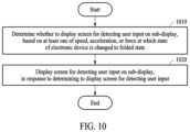
- FIG. 10 is a flowchart illustrating an example operation of an electronic device to display a screen for detecting a user input on a sub-display according to various embodiments.
- FIG. 1 is a block diagram illustrating an example electronic device 101 in a network environment 100 according to an embodiment.
- the electronic device 101 in the network environment 100 may communicate with an electronic device 102 via a first network 198 (e.g., a short-range wireless communication network), or communicate with at least one of an electronic device 104 or a server 108 via a second network 199 (e.g., a long-range wireless communication network).
- the electronic device 101 may communicate with the electronic device 104 via the server 108 .
- the electronic device 101 may include a processor 120 , a memory 130 , an input module 150 , a sound output module 155 , a display module 160 , an audio module 170 , and a sensor module 176 , an interface 177 , a connecting terminal 178 , a haptic module 179 , a camera module 180 , a power management module 188 , a battery 189 , a communication module 190 , a subscriber identification module (SIM) 196 , or an antenna module 197 .
- at least one of the components e.g., the connecting terminal 178
- some of the components e.g., the sensor module 176 , the camera module 180 , or the antenna module 197
- the processor 120 may execute, for example, software (e.g., a program 140 ) to control at least one other component (e.g., a hardware or software component) of the electronic device 101 connected to the processor 120 , and may perform various data processing or computation. According to an embodiment, as at least part of data processing or computation, the processor 120 may store a command or data received from another component (e.g., the sensor module 176 or the communication module 190 ) in a volatile memory 132 , process the command or the data stored in the volatile memory 132 , and store resulting data in a non-volatile memory 134 .
- software e.g., a program 140
- the processor 120 may store a command or data received from another component (e.g., the sensor module 176 or the communication module 190 ) in a volatile memory 132 , process the command or the data stored in the volatile memory 132 , and store resulting data in a non-volatile memory 134 .
- the processor 120 may include a main processor 121 (e.g., a central processing unit (CPU) or an application processor (AP)), or an auxiliary processor 123 (e.g., a graphics processing unit (GPU), a neural processing unit (NPU), an image signal processor (ISP), a sensor hub processor, or a communication processor (CP)) that is operable independently of, or in conjunction with the main processor 121 .
- a main processor 121 e.g., a central processing unit (CPU) or an application processor (AP)
- auxiliary processor 123 e.g., a graphics processing unit (GPU), a neural processing unit (NPU), an image signal processor (ISP), a sensor hub processor, or a communication processor (CP)
- the auxiliary processor 123 may be adapted to consume less power than the main processor 121 or to be specific to a specified function.
- the auxiliary processor 123 may be implemented separately from the main processor 121 or as a part of the main processor 121 .
- the auxiliary processor 123 may control at least some of functions or states related to at least one (e.g., the display module 160 , the sensor module 176 , or the communication module 190 ) of the components of the electronic device 101 , instead of the main processor 121 while the main processor 121 is in an inactive (e.g., sleep) state or along with the main processor 121 while the main processor 121 is an active state (e.g., executing an application).
- the auxiliary processor 123 e.g., an ISP or a CP
- the auxiliary processor 123 may include a hardware structure specified for processing of an artificial intelligence model.
- the artificial intelligence model may be generated by machine learning. Such learning may be performed by, for example, the electronic device 101 in which artificial intelligence is performed, or performed via a separate server (e.g., the server 108 ).
- a learning algorithm may include, but is not limited to, for example, supervised learning, unsupervised learning, semi-supervised learning, or reinforcement learning.
- the artificial intelligence model may include a plurality of artificial neural network layers.
- An artificial neural network may include, for example, a deep neural network (DNN), a convolutional neural network (CNN), a recurrent neural network (RNN), a restricted Boltzmann machine (RBM), a deep belief network (DBN), a bidirectional recurrent deep neural network (BRDNN), a deep Q-network, or a combination of two or more thereof, but is not limited thereto.
- the artificial intelligence model may additionally or alternatively include a software structure other than the hardware structure.
- the memory 130 may store a variety of data used by at least one component (e.g., the processor 120 or the sensor module 176 ) of the electronic device 101 .
- the data may include, for example, software (e.g., the program 140 ) and input data or output data for a command related thereto.
- the memory 130 may include the volatile memory 132 or the non-volatile memory 134 .
- the program 140 may be stored as software in the memory 130 and may include, for example, an operating system (OS) 142 , middleware 144 , or an application 146 .
- OS operating system
- middleware middleware
- application application
- the input module 150 may receive a command or data to be used by another component (e.g., the processor 120 ) of the electronic device 101 , from the outside (e.g., a user) of the electronic device 101 .
- the input module 150 may include, for example, a microphone, a mouse, a keyboard, a key (e.g., a button), or a digital pen (e.g., a stylus pen).
- the sound output module 155 may output a sound signal to the outside of the electronic device 101 .
- the sound output module 155 may include, for example, a speaker or a receiver.
- the speaker may be used for general purposes, such as playing multimedia or playing record.
- the receiver may be used to receive an incoming call. According to an embodiment, the receiver may be implemented separately from the speaker or as a part of the speaker.
- the display module 160 may visually provide information to the outside (e.g., a user) of the electronic device 101 .
- the display module 160 may include, for example, a display, a hologram device, or a projector and control circuitry to control a corresponding one of the display, the hologram device, and the projector.
- the display module 160 may include a touch sensor adapted to detect a touch, or a pressure sensor adapted to measure the intensity of force incurred by the touch.
- the audio module 170 may convert a sound into an electric signal or vice versa. According to an embodiment, the audio module 170 may obtain the sound via the input module 150 , or output the sound via the sound output module 155 or an external electronic device (e.g., the electronic device 102 such as a speaker or a headphone) directly or wirelessly connected to the electronic device 101 .
- an external electronic device e.g., the electronic device 102 such as a speaker or a headphone
- the sensor module 176 may detect an operational state (e.g., power or temperature) of the electronic device 101 or an environmental state (e.g., a state of a user) external to the electronic device 101 , and generate an electric signal or data value corresponding to the detected state.
- the sensor module 176 may include, for example, a gesture sensor, a gyro sensor, an atmospheric pressure sensor, a magnetic sensor, an acceleration sensor, a grip sensor, a proximity sensor, a color sensor, an infrared (IR) sensor, a biometric sensor, a temperature sensor, a humidity sensor, or an illuminance sensor.
- the interface 177 may support one or more specified protocols to be used for the electronic device 101 to be coupled with the external electronic device (e.g., the electronic device 102 ) directly (e.g., by wire) or wirelessly.
- the interface 177 may include, for example, a high-definition multimedia interface (HDMI), a universal serial bus (USB) interface, a secure digital (SD) card interface, or an audio interface.
- HDMI high-definition multimedia interface
- USB universal serial bus
- SD secure digital
- the connecting terminal 178 may include a connector via which the electronic device 101 may be physically connected to an external electronic device (e.g., the electronic device 102 ).
- the connecting terminal 178 may include, for example, an HDMI connector, a USB connector, an SD card connector, or an audio connector (e.g., a headphone connector).
- the haptic module 179 may convert an electric signal into a mechanical stimulus (e.g., a vibration or a movement) or an electrical stimulus which may be recognized by a user via his or her tactile sensation or kinesthetic sensation.
- the haptic module 179 may include, for example, a motor, a piezoelectric element, or an electric stimulator.
- the camera module 180 may capture a still image and moving images.
- the camera module 180 may include one or more lenses, image sensors, image signal processors, or flashes.
- the power management module 188 may manage power supplied to the electronic device 101 .
- the power management module 188 may be implemented as, for example, at least a part of a power management integrated circuit (PMIC).
- PMIC power management integrated circuit
- the battery 189 may supply power to at least one component of the electronic device 101 .
- the battery 189 may include, for example, a primary cell which is not rechargeable, a secondary cell which is rechargeable, or a fuel cell.
- the communication module 190 may support establishing a direct (e.g., wired) communication channel or a wireless communication channel between the electronic device 101 and the external electronic device (e.g., the electronic device 102 , the electronic device 104 , or the server 108 ) and performing communication via the established communication channel.
- the communication module 190 may include one or more CPs that are operable independently of the processor 120 (e.g., an AP) and that support a direct (e.g., wired) communication or a wireless communication.
- the communication module 190 may include a wireless communication module 192 (e.g., a cellular communication module, a short-range wireless communication module, or a global navigation satellite system (GNSS) communication module) or a wired communication module 194 (e.g., a local area network (LAN) communication module, or a power line communication (PLC) module).
- a wireless communication module 192 e.g., a cellular communication module, a short-range wireless communication module, or a global navigation satellite system (GNSS) communication module
- GNSS global navigation satellite system
- wired communication module 194 e.g., a local area network (LAN) communication module, or a power line communication (PLC) module.
- LAN local area network
- PLC power line communication
- a corresponding one of these communication modules may communicate with the external electronic device 104 via the first network 198 (e.g., a short-range communication network, such as BluetoothTM, wireless-fidelity (Wi-Fi) direct, or infrared data association (IrDA)) or the second network 199 (e.g., a long-range communication network, such as a legacy cellular network, a 5G network, a next-generation communication network, the Internet, or a computer network (e.g., a LAN or a wide area network (WAN))).
- first network 198 e.g., a short-range communication network, such as BluetoothTM, wireless-fidelity (Wi-Fi) direct, or infrared data association (IrDA)
- the second network 199 e.g., a long-range communication network, such as a legacy cellular network, a 5G network, a next-generation communication network, the Internet, or a computer network (e.g., a LAN or a wide area network
- the wireless communication module 192 may identify and authenticate the electronic device 101 in a communication network, such as the first network 198 or the second network 199 , using subscriber information (e.g., international mobile subscriber identity (IMSI)) stored in the SIM 196 .
- subscriber information e.g., international mobile subscriber identity (IMSI)
- the communication module may establish communication with a target device (e.g., the electronic device 104 ) for mirroring display.
- the wireless communication module 192 may support a 5G network after a 4G network, and next-generation communication technology, e.g., new radio (NR) access technology.
- the NR access technology may support enhanced mobile broadband (eMBB), massive machine type communications (mMTC), or ultra-reliable and low-latency communications (URLLC).
- eMBB enhanced mobile broadband
- mMTC massive machine type communications
- URLLC ultra-reliable and low-latency communications
- the wireless communication module 192 may support a high-frequency band (e.g., a mmWave band) to achieve, e.g., a high data transmission rate.
- a high-frequency band e.g., a mmWave band
- the wireless communication module 192 may support various technologies for securing performance on a high-frequency band, such as, e.g., beamforming, massive multiple-input and multiple-output (MIMO), full dimensional MIMO (FD-MIMO), an array antenna, analog beam-forming, or a large scale antenna.
- the wireless communication module 192 may support various requirements specified in the electronic device 101 , an external electronic device (e.g., the electronic device 104 ), or a network system (e.g., the second network 199 ).
- the wireless communication module 192 may support a peak data rate (e.g., 20 Gbps or more) for implementing eMBB, loss coverage (e.g., 164 dB or less) for implementing mMTC, or U-plane latency (e.g., 0.5 ms or less for each of downlink (DL) and uplink (UL), or a round trip of 1 ms or less) for implementing URLLC.
- a peak data rate e.g., 20 Gbps or more
- loss coverage e.g., 164 dB or less
- U-plane latency e.g., 0.5 ms or less for each of downlink (DL) and uplink (UL), or a round trip of 1 ms or less
- the antenna module 197 may transmit or receive a signal or power to or from the outside (e.g., the external electronic device) of the electronic device 101 .
- the antenna module 197 may include an antenna including a radiating element including a conductive material or a conductive pattern formed in or on a substrate (e.g., a printed circuit board (PCB)).
- the antenna module 197 may include a plurality of antennas (e.g., array antennas). In such a case, at least one antenna appropriate for a communication scheme used in a communication network, such as the first network 198 or the second network 199 , may be selected by, for example, the communication module 190 from the plurality of antennas.
- the signal or the power may be transmitted or received between the communication module 190 and the external electronic device via the at least one selected antenna.
- another component e.g., a radio frequency integrated circuit (RFIC)
- RFIC radio frequency integrated circuit
- the antenna module 197 may form a mmWave antenna module.
- the mmWave antenna module may include a PCB, an RFIC disposed on a first surface (e.g., a bottom surface) of the PCB or adjacent to the first surface and capable of supporting a designated a high-frequency band (e.g., the mmWave band), and a plurality of antennas (e.g., array antennas) disposed on a second surface (e.g., a top or a side surface) of the PCB, or adjacent to the second surface and capable of transmitting or receiving signals in the designated high-frequency band.
- At least some of the above-described components may be coupled mutually and communicate signals (e.g., commands or data) therebetween via an inter-peripheral communication scheme (e.g., a bus, general purpose input and output (GPIO), serial peripheral interface (SPI), or mobile industry processor interface (MIPI)).
- an inter-peripheral communication scheme e.g., a bus, general purpose input and output (GPIO), serial peripheral interface (SPI), or mobile industry processor interface (MIPI)
- commands or data may be transmitted or received between the electronic device 101 and the external electronic device 104 via the server 108 coupled with the second network 199 .
- Each of the external electronic devices 102 or 104 may be a device of the same type as or a different type from the electronic device 101 .
- all or some of operations to be executed by the electronic device 101 may be executed at one or more external electronic devices (e.g., the external electronic devices 102 and 104 , and the server 108 ).
- the electronic device 101 may request the one or more external electronic devices to perform at least part of the function or the service.
- the one or more external electronic devices receiving the request may perform the at least part of the function or the service requested, or an additional function or an additional service related to the request, and may transfer an outcome of the performing to the electronic device 101 .
- the electronic device 101 may provide the outcome, with or without further processing of the outcome, as at least part of a reply to the request.
- the electronic device 101 may provide ultra low-latency services using, e.g., distributed computing or MEC.
- the external electronic device 104 may be a target device with a target display that may output an image.
- the external electronic device 104 may include an Internet-of-things (IoT) device.
- the server 108 may be an intelligent server using machine learning and/or a neural network.
- the external electronic device 104 or the server 108 may be included in the second network 199 .
- the electronic device 101 may be applied to intelligent services (e.g., a smart home, a smart city, a smart car, or healthcare) based on 5G communication technology or IoT-related technology.
- FIG. 2 A is a diagram illustrating an unfolded state of an electronic device 200 according to various embodiments.
- FIG. 2 B is a diagram illustrating a folded state of the electronic device 200 according to various embodiments.
- FIGS. 2 C and 2 D are perspective views illustrating an example of a fully unfolded state and a partially unfolded intermediate state (hereinafter, referred to as an “intermediate state”) of the electronic device 200 according to various embodiments.
- the electronic device 200 of FIGS. 2 A and 2 B is an example of the electronic device 101 of FIG. 1 , and may be a foldable or bendable electronic device.
- FIG. 2 C FIG. 2 D and other following drawings, illustrated is a spatial coordinate system defined by an X-axis, a Y-axis, and a Z-axis that are orthogonal to each other.
- the X-axis may represent a width direction of an electronic device
- the Y-axis may represent a length direction of the electronic device
- the Z-axis may represent a height (or thickness) direction of the electronic device.
- a “first direction” may refer to a direction parallel to the Z-axis.
- the electronic device 200 may include a foldable housing 201 , and a flexible or foldable display 250 (hereinafter, the “display” 250 in short) (e.g., the display module 160 of FIG. 1 ) disposed in a space formed by the foldable housing 201 .
- a surface on which the display 250 is disposed (or a surface on which the display 250 is viewed from the outside of the electronic device 200 ) may be defined as a front surface of the electronic device 200 .
- a surface opposite to the front surface may be defined as a rear surface of the electronic device 200 .
- a surface surrounding a space between the front surface and the rear surface may be defined as a side surface of the electronic device 200 .
- the foldable housing 201 may include a first housing structure 210 , a second housing structure 220 including a sensor area 222 , a first rear cover 215 , a second rear cover 225 , and a hinge structure 230 .
- the hinge structure 230 may include a hinge cover that covers a foldable portion of the foldable housing 201 .
- the foldable housing 201 of the electronic device 200 is not limited to the shape and combination shown in FIGS. 2 A and 2 B , and may be implemented in a different shape or a different combination of components.
- the first housing structure 210 and the first rear cover 215 may be integrally formed
- the second housing structure 220 and the second rear cover 225 may be integrally formed.
- the first housing structure 210 may be connected to the hinge structure 230 , and may include a first surface facing a first direction, and a second surface facing a second direction opposite to the first direction.
- the second housing structure 220 may be connected to the hinge structure 230 and may include a third surface facing a third direction and a fourth surface facing a fourth direction opposite to the third direction.
- the second housing structure 220 may rotate with respect to the first housing structure 210 about the hinge structure 230 .
- a state of the electronic device 200 may be changed to a folded state or an unfolded state.
- the first surface may face the third surface in a state in which the electronic device 200 is fully folded, and the third direction may be identical to the first direction in a state in which the electronic device 200 is fully unfolded.
- the first housing structure 210 and the second housing structure 220 may be disposed on both sides with respect to a folding axis A and generally may be symmetrical with respect to the folding axis A.
- an angle or distance between the first housing structure 210 and the second housing structure 220 may vary according to whether the state of the electronic device 200 is the unfolded state, the folded state, or an intermediate state (e.g., a partially folded state or a partially unfolded state).
- the second housing structure 220 may additionally include the sensor area 222 , in which various sensors are arranged.
- the first housing structure 210 and the second housing structure 220 may have shapes symmetrical to each other in areas other than the sensor area 222 .
- the first housing structure 210 and the second housing structure 220 may together form a recess for accommodating the display 250 .
- the recess may have at least two different widths in a direction perpendicular to the folding axis A.
- the recess may have a first width w 1 between a first portion 210 a of the first housing structure 210 parallel to the folding axis A and a first portion 220 a of the second housing structure 220 formed on a periphery of the sensor area 222 , and a second width w 2 formed by a second portion 210 b of the first housing structure 210 and a second portion 220 b of the second housing structure 220 not corresponding to the sensor area 222 and being parallel to the folding axis A.
- the second width w 2 may be greater than the first width w 1 .
- the first portion 220 a and the second portion 220 b of the second housing structure 220 may be at different distances from the folding axis A.
- the widths of the recess are not limited to the shown example.
- the recess may have a plurality of widths due to the shape of the sensor area 222 or asymmetrical portions of the first housing structure 210 and the second housing structure 220 .
- the sensor area 222 may be formed to have a predetermined (e.g., specified) area adjacent to one corner of the second housing structure 220 .
- the arrangement, shape, and size of the sensor area 222 are not limited to the shown example.
- the sensor area 222 may be provided at another corner of the second housing structure 220 or in a predetermined area between an upper corner and a lower corner.
- components embedded in the electronic device 200 to perform various functions may be exposed to the front surface of the electronic device 200 through the sensor area 222 or through one or more openings provided in the sensor area 222 .
- the components may include various types of sensors.
- the sensors may include, for example, at least one of a front camera, a receiver, or a proximity sensor.
- the sensor area 222 may not be included in the second housing structure 220 or may be formed at a position different from that shown in the drawings.
- At least a portion of the first housing structure 210 and the second housing structure 220 may be formed of a metal material or a non-metal material having a selected magnitude of rigidity to support the display 250 . At least a portion of the first housing structure 210 and the second housing structure 220 formed of the metal material may provide a ground plane for the electronic device 200 , and may be electrically connected to a ground line formed on a PCB disposed in the foldable housing 201 .
- the first rear cover 215 may be disposed on one side of the folding axis A on the rear surface of the electronic device 200 , and may have, for example, a substantially rectangular periphery that may be enclosed by the first housing structure 210 .
- the second rear cover 225 may be disposed on another side of the folding axis A on the rear surface of the electronic device 200 , and may have a periphery that may be enclosed by the second housing structure 220 .
- the first rear cover 215 and the second rear cover 225 may be substantially symmetrical with respect to the folding axis A.
- the first rear cover 215 and the second rear cover 225 are not necessarily mutually symmetrical.
- the first rear cover 215 and the second rear cover 225 in the electronic device 200 may have various shapes.
- the first rear cover 215 may be formed integrally with the first housing structure 210
- the second rear cover 225 may be formed integrally with the second housing structure 220 .
- the first rear cover 215 , the second rear cover 225 , the first housing structure 210 , and the second housing structure 220 may form a space in which various components (e.g., a PCB, or a battery) of the electronic device 200 are to be arranged.
- one or more components may be disposed or visually exposed on the rear surface of the electronic device 200 .
- at least a portion of a sub-display may be visually exposed through a first rear area 216 of the first rear cover 215 .
- one or more components or sensors may be visually exposed through a second rear area 226 of the second rear cover 225 .
- the sensors may include a proximity sensor and/or a rear camera.
- a front camera exposed to the front surface of the electronic device 200 through one or more openings provided in the sensor area 222 , or a rear camera exposed through the second rear area 226 of the second rear cover 225 may include one or more lenses, an image sensor, and/or an ISP.
- a flash may include, for example, a light emitting diode (LED) or a xenon lamp.
- two or more lenses (e.g., infrared camera, wide-angle, and telephoto lenses) and image sensors may be arranged on one surface of the electronic device 200 .
- the hinge cover may be disposed between the first housing structure 210 and the second housing structure 220 to cover internal components (e.g., the hinge structure 230 ).
- the hinge structure 230 may be covered by a portion of the first housing structure 210 and a portion of the second housing structure 220 , or may be exposed to the outside, depending on the state (e.g., the unfolded state, the intermediate state, or the folded state) of the electronic device 200 .
- the hinge structure 230 when the electronic device 200 is in the unfolded state (e.g., a fully unfolded state) as illustrated in FIG. 2 A , the hinge structure 230 may be covered by the first housing structure 210 and the second housing structure 220 not to be exposed. In another example, when the electronic device 200 is in the folded state (e.g., a fully folded state) as illustrated in FIG. 2 B , the hinge structure 230 may be exposed to the outside, being between the first housing structure 210 and the second housing structure 220 .
- the hinge cover 230 when the first housing structure 210 and the second housing structure 220 are in an intermediate state of being folded with a predetermined angle, the hinge cover 230 may be partially exposed to the outside, being between the first housing structure 210 and the second housing structure 220 .
- the exposed area may be less than that in the fully folded state.
- the hinge cover 230 may have a curved surface.
- the display 250 may be disposed in a space formed by the foldable housing 201 .
- the display 250 may be seated on the recess formed by the foldable housing 201 and may be viewed from the outside through the front surface of the electronic device 200 .
- the display 250 may include most of the front surface of the electronic device 200 .
- the front surface of the electronic device 200 may include the display 250 , and a partial area of the first housing structure 210 and a partial area of the second housing structure 220 , which are adjacent to the display 250 .
- the rear surface of the electronic device 200 may include the first rear cover 215 , a partial area of the first housing structure 210 adjacent to the first rear cover 215 , the second rear cover 225 , and a partial area of the second housing structure 220 adjacent to the second rear cover 225 .
- the display 250 may refer to a display having at least a partial area that is deformable into a flat surface or a curved surface.
- the display 250 may include a folding area 253 , a first area 251 disposed on one side of the folding area 253 (e.g., on the left side of the folding area 253 shown in FIG. 2 A ), and a second area 252 disposed on the other side of the folding area 253 (e.g., on the right side of the folding area 253 shown in FIG. 2 A ).
- the display 250 may be divided into a plurality of areas (e.g., four or more areas, or two areas) depending on a structure or functions thereof.
- the display 250 may be divided into areas based on the folding area 203 extending in parallel to the folding axis A.
- the display 250 may be divided into areas based on another folding axis (e.g., a folding axis parallel to a width direction of an electronic device).
- the display 250 may be coupled to or disposed adjacent to a touch panel including a touch sensing circuit and a pressure sensor for measuring a strength (a pressure) of a touch.
- the display 250 may be coupled to or disposed adjacent to a touch panel for detecting a stylus pen of an electromagnetic resonance (EMR) type, as an example of the touch panel.
- EMR electromagnetic resonance
- the first area 251 and the second area 252 may have globally symmetrical shapes around the folding area 253 .
- the second area 252 may include a notch that is cut depending on a presence of the sensor area 222 , but may have a shape symmetrical to the first area 251 in the other areas.
- the first area 251 and the second area 252 may include portions having mutually symmetrical shapes and portions having mutually asymmetrical shapes.
- an edge thickness of each of the first area 251 and the second area 252 may be different from an edge thickness of the folding area 253 .
- the edge thickness of the folding area 253 may be less than those of the first area 251 and the second area 252 .
- the first area 251 and the second area 252 may be asymmetrical in terms of thickness when the first area 251 and the second area 252 are cross-sectionally viewed.
- an edge of the first area 251 may be formed to have a first radius of curvature
- an edge of the second area 252 may be formed to have a second radius of curvature different from the first radius of curvature.
- the first area 251 and the second area 252 may be symmetrical in terms of thickness when the first area 251 and the second area 252 are cross-sectionally viewed.
- each area of the display 250 and operations of the first housing structure 210 and the second housing structure 220 depending on the state (e.g., the folded state, the unfolded state, or the intermediate state) of the electronic device 200 will be described.
- the state e.g., the folded state, the unfolded state, or the intermediate state
- the first housing structure 210 and the second housing structure 220 may be arranged to face the same direction while forming an angle of 180 degrees.
- the surface of the first area 251 and the surface of the second area 252 in the display 250 may face the same direction (e.g., a front direction of an electronic device), forming 180 degrees.
- the folding area 253 may form the same plane as the first area 251 and the second area 252 .
- the first housing structure 210 and the second housing structure 220 may be arranged to face each other.
- the surface of the first area 251 and the surface of the second area 252 in the display 250 may face each other, forming a narrow angle (e.g., between 0 degrees and 10 degrees).
- At least a portion of the folding area 253 may include a curved surface having a predetermined curvature.
- the first housing structure 210 and the second housing structure 220 may be arranged to form a predetermined angle therebetween.
- the surface of the first area 251 and the surface of the second area 252 in the display 250 may form an angle greater than that in the folded state and less than that in the unfolded state.
- At least a portion of the folding area 253 may include a curved surface having a predetermined curvature, and the curvature may be less than that in the folded state.
- FIG. 2 C illustrates the fully unfolded state of the electronic device 200
- FIG. 2 D illustrates the partially unfolded intermediate state of the electronic device 200
- the state of the electronic device 200 may be changed to the folded state or the unfolded state.
- the electronic device 200 when viewed in a direction of a folding axis (e.g., the folding axis A of FIG. 2 A ), the electronic device 200 may be folded in two types, e.g., an “in-folding” type in which the front surface of the electronic device 200 is folded to form an acute angle, and an “out-folding” type in which the front surface of the electronic device 200 is folded to form an obtuse angle.
- the first surface of the first housing structure 210 may face the third surface of the second housing structure 220 .
- the first surface of the first housing structure 210 and the third surface of the second housing structure 220 may face the same direction (e.g., a direction parallel to the Z-axis).
- the second surface of the first housing structure 210 may face the fourth surface of the second housing structure 220 .
- the electronic device 200 may include a plurality of hinge axes (e.g., two parallel hinge axes including the folding axis A of FIG. 2 A and another axis parallel to the folding axis A).
- the electronic device 200 may also be folded in a “multi-folding” type in which the in-folding type and the out-folding type are combined.
- the in-folding type may refer to a state in which the display 250 is not exposed to the outside in the fully folded state.
- the out-folding type may refer to a state in which the display 250 is exposed (e.g., visible) to the outside in the fully folded state.
- FIG. 2 D shows the intermediate state in which the electronic device 200 is partially unfolded in an in-folding process.
- FIGS. 3 A, 3 B, 3 C and 3 D are diagrams illustrating a fully unfolded state, a partially unfolded intermediate state, and a fully folded state of an electronic device according to various embodiments.
- an electronic device 300 may include a foldable display 330 (e.g., the display module 160 of FIG. 1 or the display 250 of FIGS. 2 A through 2 D ), a first housing 341 , and a second housing 343 .
- a state 301 may indicate a fully unfolded state or an unfolded state of the electronic device 300 .
- the electronic device 300 may be folded.
- the electronic device 300 may be folded.
- the electronic device 300 may be folded.
- a first area 331 and a second area 333 of the foldable display 330 may form an angle ⁇ based on a folding axis as in states 303 and 305 .
- the states 303 and 305 may also be referred to as “partially unfolded intermediate states”, and the angle ⁇ formed by the first area 331 and the second area 333 may also be referred to as a “folding angle”.
- the folding angle in the partially unfolded intermediate state 303 may be about 135 degrees, and the folding angle in the partially unfolded intermediate state 305 may be about 45 degrees.
- a state 307 may be a state in which the electronic device 300 is fully folded.
- the electronic device 300 may be folded such that the first area 331 and the second area 333 may face each other.
- a screen may be folded inwards.
- the above folding scheme may also be referred to as an in-folding scheme.
- the electronic device 300 may be folded such that the first area 331 and the second area 333 may be oriented in opposite directions. In other words, the screen may be folded outwards.
- FIG. 4 is a flowchart illustrating an example screen display operation of an electronic device according to various embodiments.
- an electronic device may display a graphic object on a partial area of a main display, in response to a state of the electronic device that is executing an application being changed to a partially unfolded intermediate state.
- the graphic object may include a graphic object to provide a user with visual feedback associated with a determination of a display (e.g., the main display or a sub-display) on which a screen of an application is to be displayed.
- the electronic device may include a display module including a main display and a sub-display.
- the electronic device may activate the main display (e.g., the display 250 of FIGS. 2 A through 2 D ).
- the electronic device may activate the sub-display (e.g., a sub-display exposed (e.g., visible) through the first rear area 216 of the first rear cover 215 of FIGS. 2 A through 2 D ).
- the graphic object may include a graphic object associated with switching a screen display of an application being executed by the electronic device from the main display to the sub-display when the state of the electronic device is changed from the intermediate state to the folded state.
- the graphic object may be used to inform a user of whether the screen of the application is to be displayed on the sub-display when the electronic device is in the folded state, according to a position in which the graphic object is displayed when the electronic device is in the intermediate state.
- the electronic device may display the screen of the application on the sub-display.
- the electronic device may skip displaying the screen of the application on the sub-display.
- the user may determine whether the screen of the application is to be displayed on the sub-display when the electronic device is in the folded state, depending on whether the graphic object is displayed in the predetermined position when the electronic device is in the intermediate state.
- the user may determine whether to display the screen of the application on the sub-display according to intention of the user, by adjusting a speed and/or a point in time at which the state of the electronic device is changed to the folded state. For example, the user may maintain the intermediate state of the electronic device until the graphic object is displayed in the predetermined position so that the electronic device may display the screen of the application on the sub-display. After the graphic object is displayed in the predetermined position, the user may change the state of the electronic device to the folded state. For example, the user may quickly change the state of the electronic device so that the electronic device may skip displaying the screen of the application on the sub-display, thereby changing the state of the electronic device to the folded state before the graphic object is displayed in the predetermined position.
- the electronic device may display the screen of the application on the sub-display, in response to the graphic object being displayed in the predetermined position before the state of the electronic device is changed to the folded state.
- the electronic device may switch the screen display of the application from the main display to the sub-display, in response to the graphic object being displayed in the predetermined position before the state of the electronic device is changed to the folded state. If the electronic device is in at least one of the unfolded state or the partially unfolded intermediate state, the electronic device may display the screen of the application on the main display.
- the electronic device may display the graphic object in a predetermined position of the main display, and when the state of the electronic device is changed to the folded state, display the screen of the application on the sub-display.
- the electronic device may maintain execution of the application.
- the electronic device may play an output including a sound generated while the application is being executed.
- the electronic device may play a sound corresponding to the notification or generate a vibration corresponding to the notification.
- the electronic device may stop displaying the screen of the application on the sub-display.
- the electronic device may adjust the order of the screen of the application and other screens (e.g., screens of other applications, widget screens, etc.).
- the electronic device may set whether to display the screen of the application being executed on the sub-display according to a user input when the state of the electronic device is changed to the folded state. For example, in response to the state of the electronic device being changed to the folded state, the electronic device may be set to skip the displaying of the screen of the application on the sub-display, according to a user input.
- the electronic device may display the graphic object independently of the setting according to the user input described above. For example, even when the displaying of the screen of the application on the sub-display is set to be skipped according to a user input, the electronic device may display the graphic object.
- the electronic device may display the screen of the application on the sub-display independently of the setting according to the user input described above.
- the electronic device may display the screen of the application on the sub-display.
- the electronic device in response to the electronic device being in the folded state, may stop displaying the graphic object on a partial area of the main display.
- the electronic device may determine one of the main display and the sub-display, which is to be activated according to the state of the electronic device. For example, when the state of the electronic device is at least one of the unfolded state or the partially unfolded intermediate state, the electronic device may activate the main display and deactivate the sub-display. When the electronic device is in the folded state, the main display may be deactivated, and the sub-display may be activated. In response to the electronic device being in the folded state, the electronic device may deactivate the main display to stop displaying the graphic object that has been displayed on a partial area of the main display.
- the electronic device may skip the displaying of the screen of the application on the sub-display in response to the state of the electronic device being changed to the folded state before the graphic object is displayed in the predetermined position. For example, when being in the intermediate state, the electronic device may not display the graphic object in the predetermined position. The state of the electronic device may be changed to the folded state. When the electronic device is in the folded state, the electronic device may skip the displaying of the screen of the application on the sub-display.
- FIG. 5 is a flowchart illustrating an example operation of an electronic device to display a graphic object according to various embodiments.
- an electronic device e.g., the electronic device 101 of FIG. 1 , and the electronic device 200 of FIGS. 2 A through 2 D ) may determine whether to display a graphic object, in response to a state of the electronic device being changed to an intermediate state.
- the electronic device may determine whether to display the graphic object, based on at least one of a speed or an acceleration at which the state of the electronic device is changed to the intermediate state. For example, when at least one of receiving an input from a user, playing continuous content, or detecting an interaction from the user is currently performed at a point in time at which the state of the electronic device is changed to the intermediate state, the electronic device may determine to display the graphic object. An operation of determining whether to display a graphic object will be described in greater detail below with reference to FIG. 7 .
- the electronic device may display the graphic object on a partial area of the main display, in response to determining to display the graphic object.
- the electronic device may display the graphic object on a partial area determined in consideration of a gaze of a user among screen areas of the main display.
- the electronic device may display the graphic object on a partial area of the main display corresponding to a detected gaze of a user.
- the electronic device may display the graphic object on a partial area determined in consideration of an area of the main display covered by a first housing structure (e.g., the first housing structure 210 of FIGS. 2 A through 2 D ), when viewed in a direction opposite to a height direction (e.g., a Z-axis direction of FIGS. 2 A through 2 D ) of the electronic device.
- a first housing structure e.g., the first housing structure 210 of FIGS. 2 A through 2 D
- a height direction e.g., a Z-axis direction of FIGS. 2 A through 2 D
- the electronic device may display the graphic object on a portion of areas of the main display other than the area covered by the first housing structure.
- the electronic device in response to the state of the electronic device being changed to the intermediate state, may display the graphic object in a first position on a partial area of the main display.
- the electronic device may display at least a portion of the graphic object on an area including a point of the main display corresponding to the first position.
- the electronic device may display the graphic object in a second position (e.g., a predetermined position) on the partial area of the main display.
- the electronic device may display at least a portion of the graphic object on an area including a point of the main display corresponding to the second position (e.g., a predetermined position) on the partial area of the main display.
- the electronic device may display the graphic object in the first position.
- a threshold folding angle e.g., 45 degrees
- the electronic device may display the graphic object in the second position.
- the electronic device may change a central position of the graphic object from the first position to the second position, to display the graphic object in the second position.
- the threshold angle range e.g., the range of 5 degrees to 45 degrees
- the electronic device may change a shape of the graphic object to display the graphic object in the second position.
- the electronic device in response to the state of the electronic device being the intermediate state in which the electronic device is folded at the threshold folding angle (e.g., 45 degrees), the electronic device may display the graphic object in the first position.
- the electronic device may increase an area and/or a length of the displayed graphic object, to display the graphic object across the first position and the second position (e.g., the predetermined position). For example, the electronic device may display the graphic object in an area including a point corresponding to the first position and a point corresponding to the second position (e.g., a predetermined position), to display the graphic object in the second position (e.g., the predetermined position).
- the electronic device may increase an area and/or a length of the displayed graphic object, to display the graphic object across the first position and the second position (e.g., the predetermined position).
- the electronic device may display the graphic object in an area including a point corresponding to the first position and a point corresponding to the second position (e.g., a predetermined position), to display the graphic object in the second position (e.g., the predetermined position).
- the electronic device may skip displaying of the graphic object on the main display in response to determining not to display the graphic object.
- the electronic device may display the graphic object in a predetermined position on the partial area of the main display, in response to the intermediate state of the electronic device being maintained for the threshold length of time.
- the electronic device may display the graphic object in the predetermined position on the partial area of the main display, in response to remaining in the intermediate state in which the electronic device is folded at the folding angle falling within the threshold angle range (e.g., the range of 5 degrees to 45 degrees).
- the predetermined position may include a position corresponding to a point on the main display in association with whether the electronic device is to display the screen of the application on the sub-display when the electronic device is in the folded state.
- FIG. 6 A is a diagram illustrating an example operation of an electronic device to display a graphic object when a folding axis of the electronic device is parallel to a length direction of the electronic device according to various embodiments.
- FIG. 6 B is a diagram illustrating an example operation of an electronic device to display a graphic object when a folding axis of the electronic device is parallel to a width direction of the electronic device according to various embodiments.
- a foldable display (e.g., the display 250 of FIGS. 2 A through 2 D ) included in an electronic device 600 a (e.g., the electronic device 101 of FIG. 1 , and the electronic device 200 of FIGS. 2 A through 2 D ) may have a folding axis extending in a direction (e.g., a vertical direction) parallel to a length direction of the electronic device 600 a.
- a direction e.g., a vertical direction
- the electronic device 600 a may include a main display 650 a (e.g., the display module 160 of FIG. 1 , and the display 250 of FIGS. 2 A through 2 D ), and a foldable housing 601 a .
- the foldable housing 601 a may include a first housing structure 610 a , and a second housing structure 620 a .
- the main display 650 a may be divided into a first area 651 a and a second area 652 a based on a folding axis 653 a of a hinge.
- the first area 651 a and the second area 652 a of the main display 650 a may have a rectangular shape with curved corners and a narrow bezel.
- a foldable display (e.g., the display 260 of FIGS. 2 A through 2 D ) included in an electronic device 600 b (e.g., the electronic device 101 of FIG. 1 , and the electronic device 200 of FIGS. 2 A through 2 D ) may have a folding axis extending in a direction (e.g., a horizontal direction) parallel to a width direction of the electronic device 600 b.
- a direction e.g., a horizontal direction
- the electronic device 600 b may include a main display 680 b (e.g., the display module 160 of FIG. 1 , and the display 250 of FIGS. 2 A through 2 D ), and a foldable housing 690 b .
- the foldable housing 690 b may include a first housing structure 691 b , and a second housing structure 693 b .
- the main display 680 b may be divided into a first area 681 b and a second area 683 b based on a folding axis 670 b of a hinge.
- the first area 681 b and the second area 683 b of the main display 680 b may have a rectangular shape with curved corners and a narrow bezel.
- the electronic device 600 a or 600 b may determine whether to display a graphic object 630 a or 630 b .
- the electronic device 600 a or 600 b may determine to display the graphic object 630 a or 630 b based on at least one of a speed or an acceleration at which the state of the electronic device 600 a or 600 b is changed to an intermediate state in which the electronic device 600 a or 600 b is folded at a threshold folding angle (e.g., 45 degrees).
- the electronic device 600 a or 600 b may display the graphic object 630 a or 630 b on a partial area of the main display 650 a or 680 b.
- the partial area may be determined in consideration of an area of the main display 650 a or 680 b covered by the first housing structure 610 a or 691 b , when viewed in a direction opposite to a height direction (e.g., the Z-axis direction of FIGS. 2 A through 2 D ) of the electronic device 600 a or 600 b .
- the partial area may include areas other than the area of the main display 650 a or 680 b covered by the first housing structure 610 a or 691 b , when viewed in the direction opposite to the height direction of the electronic device 600 a or 600 b , in a partially unfolded state of the electronic device 600 a or 600 b .
- the partial area may be determined as areas other than the area of the main display 650 a or 680 b covered by the first housing structure 610 a or 691 b , when viewed in the direction opposite to the height direction of the electronic device 600 a or 600 b.
- a predetermined folding angle e.g. 30 degrees
- the electronic device 600 a or 600 b may further display a guide object 640 a or 640 b together with the graphic object 630 a or 630 b .
- the guide object 640 a or 640 b may include an object to inform a user of a predetermined position 660 a or 660 b on the main display 650 a or 680 b .
- the predetermined position 660 a or 660 b may be, for example, a position associated with whether the electronic device 600 a or 600 b is to switch a screen display of the application from the main display 650 a or 680 b to a sub-display.
- the electronic device 600 a or 600 b may display the graphic object 630 a or 630 b in a first position on a screen area of the main display 650 a or 680 b , in response to the state of the electronic device 600 a or 600 b being changed to the partially unfolded intermediate state.
- the electronic device may display a graphic object in a second position (e.g., the predetermined position 660 a or 660 b ).
- the electronic device 600 a or 600 b may display the graphic object 630 a or 630 b in the first position.
- the electronic device 600 a or 600 b may increase and display an area and/or length of the graphic object 630 a or 630 b .
- the electronic device 600 a or 600 b may display the graphic object 630 a or 630 b in the second position (e.g., the predetermined position 660 a or 660 b ).
- the electronic device 600 a or 600 b may display the graphic object 630 a or 630 b in a predetermined position before the state of the electronic device 600 a or 600 b is changed to a folded state.
- the electronic device 600 a or 600 b may display a screen of the application on the sub-display.
- the electronic device 600 a or 600 b may switch the screen display of the application being executed from the main display 650 a or 680 b to the sub-display.
- FIG. 7 is a flowchart illustrating an example operation of an electronic device to determine whether to display a graphic object according to various embodiments.
- an electronic device may determine whether to display a graphic object, in response to a state of the electronic device being changed to a partially unfolded intermediate state. For example, in response to the electronic device being in an intermediate state of being folded at a threshold folding angle (e.g., 45 degrees), the electronic device may determine whether to display the graphic object.
- a threshold folding angle e.g. 45 degrees
- the electronic device may determine whether to display the graphic object based on at least one of a speed or an acceleration at which the state of the electronic device is changed.
- the speed at which the state of the electronic device is changed may include a speed at which a folding angle (e.g., the folding angle ⁇ of FIGS. 3 A to 3 D ) formed by a first area (e.g., the first area 251 of FIGS. 2 A through 2 D ) and a second area (e.g., the second area 252 of FIGS. 2 A through 2 D ) in the state of the electronic device is changed.
- the speed at which the state of the electronic device is changed may include an angular velocity (e.g., a variation in a folding angle per unit time) of a folding angle of the electronic device.
- the electronic device may determine whether to display the graphic object based on a speed at which the state of the electronic device is changed to the intermediate state.
- the electronic device may determine whether to display the graphic object based on an instantaneous angular velocity corresponding to a point in time at which the state of the electronic device is changed to the intermediate state in which the electronic device is folded at the threshold folding angle.
- the electronic device may compare the above-described instantaneous angular velocity to a threshold angular velocity, to determine whether to display the graphic object.
- the instantaneous angular velocity may refer to an angular velocity of a folding angle for an extremely short period of time including the point in time at which the state of the electronic device is changed to the intermediate state in which the electronic device is folded at the threshold folding angle.
- the electronic device may determine whether to display the graphic object based on an average angular velocity during a period in which the electronic device is in an intermediate state of being folded at a folding angle within a threshold angle range (e.g., a range of 45 degrees to 90 degrees).
- the electronic device may compare the above-described average angular velocity to the threshold angular velocity, to determine whether to display the graphic object.
- the average angular velocity may refer to an angular velocity of a folding angle during the period in which the electronic device is in the intermediate state of being folded at the folding angle within a threshold angle range (e.g., a range of 45 degrees to 90 degrees).
- the speed at which the state of the electronic device is changed may be described as an angular velocity of the folding angle herein, however, embodiments are not limited thereto.
- the speed at which the state of the electronic device is changed may include a speed with respect to a distance between one point (e.g., a point corresponding to a Hall sensor) and another point (e.g., a point corresponding to a magnetic body) of the electronic device.
- the acceleration at which the state of the electronic device is changed may include an acceleration at which a folding angle formed by a first area (e.g., the first area 251 of FIGS. 2 A through 2 D ) and a second area (e.g., the second area 252 of FIGS. 2 A through 2 D ) in the state of the electronic device is changed.
- the acceleration at which the state of the electronic device is changed may include an angular acceleration (e.g., a variation in a folding angular velocity per unit time) of the folding angle of the electronic device.
- the electronic device may determine whether to display the graphic object based on an acceleration at which the state of the electronic device is changed to the intermediate state.
- the electronic device may determine whether to display the graphic object based on an instantaneous angular acceleration corresponding to a point in time at which the state of the electronic device is changed to the intermediate state in which the electronic device is folded at the threshold folding angle.
- the electronic device may compare the above-described instantaneous angular acceleration to a threshold angular acceleration, to determine whether to display the graphic object.
- the instantaneous angular acceleration may refer to an angular acceleration (e.g., a variation in an angular velocity per unit time) for an extremely short period of time including the point in time at which the state of the electronic device is changed to the intermediate state in which the electronic device is folded at the threshold folding angle.
- an angular acceleration e.g., a variation in an angular velocity per unit time
- the electronic device may determine whether to display the graphic object based on an average angular acceleration during a period in which the electronic device is in the intermediate state of being folded at the folding angle within the threshold angle range (e.g., a range of 45 degrees to 90 degrees).
- the electronic device may compare the above-described average angular acceleration to the threshold angular acceleration, to determine whether to display the graphic object.
- the average angular acceleration may refer to an angular acceleration (e.g., a variation in an angular velocity per unit time) during the period in which the electronic device is in the intermediate state of being folded at the folding angle within the threshold angle range (e.g., a range of 45 degrees to 90 degrees).
- an angular acceleration e.g., a variation in an angular velocity per unit time
- a folding angle formed by a foldable display of the electronic device and calculation of an angular velocity and an angular acceleration for the folding angle will be further described in greater detail below with reference to FIG. 8 .
- the acceleration at which the state of the electronic device is changed may be described as an angular acceleration of the folding angle herein, however, embodiments are not limited thereto.
- the acceleration at which the state of the electronic device is changed may include an acceleration with respect to a distance between one point (e.g., a point corresponding to a Hall sensor) and another point (e.g., a point corresponding to a magnetic body) of the electronic device.
- the electronic device may determine to display the graphic object, in response to currently playing consecutive content at a point in time at which the state of the electronic device is changed to the intermediate state. For example, the electronic device may determine to display the graphic object on a partial area of a main display, in response to currently playing at least one of audio or video.
- the electronic device may perform an operation of switching a screen display of an application to a sub-display by displaying the graphic object. If the graphic object is displayed in a predetermined position, a user may change the state of the electronic device to a folded state.
- the electronic device may display the screen of the application without interruption by switching the screen display of the application from the main display to the sub-display.
- the electronic device may play consecutive content without interruption while the state of the electronic device is being changed to the folded state.
- the electronic device may determine to display the graphic object, in response to currently receiving an input from a user at the point in time at which the state of the electronic device is changed to the intermediate state. For example, the electronic device may determine to display the graphic object on a partial area of the main display, in response to currently receiving at least one of a voice input or a text input.
- the electronic device may be receiving a voice input from a user at the point in time at which the state of the electronic device is changed to the intermediate state.
- the electronic device may receive a voice input with an utterance of a user for wired calling with another user through a call application from the user. While the electronic device is receiving the voice input from the user, the state of the electronic device may be changed to the intermediate state in which the electronic device is folded at the threshold folding angle (e.g., 45 degrees).
- the threshold folding angle e.g. 45 degrees
- the electronic device may be receiving a text input from the user at the point in time at which the state of the electronic device is changed to the intermediate state.
- the electronic device may receive a text input from the user through an input device (e.g., a keyboard) that communicates with the electronic device by wire and/or wirelessly. While the electronic device is receiving the text input from the user, the state of the electronic device may be changed to the intermediate state in which the electronic device is folded at the threshold folding angle (e.g., 45 degrees).
- the threshold folding angle e.g. 45 degrees
- the electronic device when the electronic device is receiving an input (e.g., a voice input, a text input, etc.) at the point in time at which the state of the electronic device is changed to the intermediate state, the electronic device may perform an operation of switching the screen display of the application from the main display to the sub-display by displaying the graphic object. If the graphic object is displayed in a predetermined position, the user may change the state of the electronic device to the folded state. The electronic device may maintain execution of the application while the state of the electronic device is being changed. The electronic device may receive the input from the user without interruption by maintaining the execution of the application. While the state of the electronic device is being changed to the folded state, the electronic device may receive the input from the user without interruption.
- an input e.g., a voice input, a text input, etc.
- the electronic device may determine to display the graphic object, in response to detecting that a user gazes at the electronic device at the point in time at which the state of the electronic device is changed to the intermediate state. For example, in response to detecting that the user gazes at a predetermined area of the electronic device, the electronic device may determine to display the graphic object.
- the predetermined area may include a partial area (e.g., a partial area on which a graphic object is displayed) of the main display.
- the predetermined area may include a screen area of the sub-display.
- the electronic device may perform the operation of switching the screen display of the application to the sub-display by displaying the graphic object. If the graphic object is displayed in a predetermined position, the user may change the state of the electronic device to the folded state.
- the electronic device may display the screen of the application without interruption by switching the screen display of the application from the main display to the sub-display. To view the screen of the application even after the electronic device is changed to the folded state, the user may gaze at a predetermined area when the electronic device is in the intermediate state.
- FIG. 8 is a block diagram illustrating an example configuration of an electronic device according to various embodiments.
- An electronic device 800 (e.g., the electronic device 101 of FIG. 1 , and the electronic device 200 of FIGS. 2 A through 2 D ) according to an embodiment may include a hinge 810 configured to allow the electronic device 800 to be folded or unfolded, a foldable display 820 (e.g., the display 250 of FIGS.
- a sensor module e.g., including at least one sensor
- a processor e.g., including processing circuitry
- input module e.g. input module 150 of FIG. 1
- the processor 840 may include various processing circuitry and determine the state of the electronic device 800 to be one of an unfolded state corresponding to a state in which the foldable display 820 is unfolded, a partially unfolded intermediate state in which the foldable display 820 forms a folding angle within a predefined folding angle range, and a folded state corresponding to a state in which the foldable display 820 is folded.
- the hinge 810 may allow the electronic device 800 to be folded or unfolded. As the electronic device 800 is folded or unfolded around the hinge 810 , the foldable display 820 may also be folded or unfolded.
- the foldable display 820 may be disposed on at least one side of the electronic device 800 and may include a first area 821 (e.g., the first area 251 of FIGS. 2 A through 2 D ) disposed on one side of the hinge 810 and a second area 823 (e.g., the second area 252 of FIGS. 2 A through 2 D ) disposed on the other side of the hinge 810 .
- the sensor module 830 may include at least one sensor and detect a folding angle (e.g., the folding angle ⁇ of FIGS. 3 A to 3 D ) of the electronic device 800 .
- the sensor module 830 may be a Hall sensor, an acceleration sensor, and/or a gyro sensor (e.g., a gyroscope), and the acceleration sensor and/or the gyro sensor may detect the folding angle of the electronic device 800 .
- the sensor module 830 may be disposed inside the hinge 810 to detect the folding angle by detecting the number of rotations of a gear.
- the sensor module 830 may detect a point in time at which folding is started and an angle at which folding stops, in addition to the folding angle.
- the sensor module 830 may be a Hall sensor.
- the Hall sensor may be a transducer for generating an electrical signal (e.g., a voltage) in response to a magnetic field.
- the Hall sensor may generate an electrical signal with a relatively high intensity when the magnetic field has a high intensity, and may generate an electrical signal with a relatively low intensity when the magnetic field has a low intensity.
- the Hall sensor may be positioned in a first housing structure (e.g., the first housing structure 210 of FIGS. 2 A through 2 D ), and an element (e.g., a magnetic body) for generating a magnetic field may be positioned in a second housing structure (e.g., the second housing structure 220 of FIGS. 2 A through 2 D ).
- the Hall sensor may be positioned in the second housing structure, and a magnetic body may be positioned in the first housing structure. If the state of the electronic device 800 is changed from a fully unfolded state to the folded state, the Hall sensor may approach the magnetic body and detect the folded state of the foldable display 820 in response to a magnetic field of the magnetic body. In addition, the Hall sensor may detect the folding angle via an intensity of an electrical signal generated in response to the magnetic field.
- the Hall sensor is an example of the sensor module 830 , and the sensor module 830 is not limited to the Hall sensor.
- a magnetic (geomagnetic) sensor and a Hall sensor may be used to detect the folding angle of the electronic device 800 .
- the magnetic (geomagnetic) sensor and the Hall sensor may include a transmitter to generate a magnetic field of a predetermined frequency and a receiver to receive the magnetic field generated by the transmitter, and may detect the folding angle based on a change in the state of the electronic device 800 .
- the magnetic (geomagnetic) sensor may measure an orientation using a magnetic field and magnetic force lines, and the Hall sensor may identify the change in the state of the electronic device 800 by detecting the strength of the magnetic field and may detect the folding angle (e.g., the folding angle ⁇ of FIGS. 3 A to 3 D ).
- the processor 840 may detect the folded state of the foldable display 820 based on a sensing result of the sensor module 830 and calculate the folding angle. For example, the processor 840 may receive an electrical signal according to a detection of the magnetic field from the Hall sensor. The processor 840 may detect the folded state of the foldable display 820 by receiving the electrical signal from the Hall sensor. In addition, the processor 840 may calculate the folding angle of the foldable display 820 based on the intensity of the electrical signal received from the Hall sensor.
- the processor 840 may calculate at least one of a speed or an acceleration at which the state of the electronic device 800 is changed, based on the folding angle.
- the processor 840 may calculate an instantaneous angular velocity of the folding angle. For example, in response to the state of the electronic device 800 being changed to the intermediate state in which the electronic device 800 is folded at the threshold folding angle (e.g., 45 degrees), the processor 840 may calculate an average angular velocity of the folding angle during a period in which the electronic device 800 is in an intermediate state of being folded at a folding angle within a threshold angle range (e.g., a range of 45 degrees to 90 degrees) of the electronic device 800 .
- a threshold folding angle range e.g., a range of 45 degrees to 90 degrees
- the processor 840 may calculate an instantaneous angular acceleration of the folding angle. For example, in response to the state of the electronic device 800 being changed to the intermediate state in which the electronic device 800 is folded at the threshold folding angle (e.g., 45 degrees), the processor 840 may calculate an average angular acceleration of the folding angle during the period in which the electronic device 800 is in the intermediate state of being folded at the folding angle within the threshold angle range (e.g., a range of 45 degrees to 90 degrees).
- the threshold angle range e.g., a range of 45 degrees to 90 degrees.
- FIG. 9 is a diagram illustrating an example operation of an electronic device to display a preview screen of an application together with a graphic object according to various embodiments.
- an electronic device 900 may be executing an application.
- the electronic device 900 may display a graphic object 930 on a partial area of a main display 950 in response to a state of the electronic device 900 being changed to a partially unfolded intermediate state.
- the electronic device 900 may display a preview screen 940 of the application on another partial area of the main display 950 in response to displaying the graphic object 930 .
- the other partial area may be partial area of the main display 950 other than an area on which the graphic object 930 is displayed.
- the preview screen 940 of the application may include a screen based on a screen that is to be displayed as a screen of the application on a sub-display 960 when the electronic device 900 is in a folded state.
- the preview screen 940 may include a screen 941 to be displayed on the sub-display 960 .
- the preview screen 940 may further include a guide message 942 together with the screen 941 to be displayed on the sub-display 960 .
- the guide message 942 may include a message associated with displaying the screen of the application on the sub-display 960 when the graphic object 930 is displayed in a predetermined position before the state of the electronic device 900 is changed to the folded state.
- the electronic device 900 may display the screen of the application on the sub-display 960 in response to displaying the graphic object 930 in a predetermined position on the partial area before the state of the electronic device 900 is changed to the folded state.
- the electronic device 900 may display the screen of the application on the sub-display 960 in response to the state of the electronic device 900 being the folded state.
- the main display 950 and the sub-display 960 may be different from each other in aspect ratio and/or screen size. Even when the electronic device 900 executes the same application, the screen of the application displayed when the main display 950 is activated may be different from the screen of the application displayed when the sub-display 960 is activated. If the state of the electronic device 900 is changed from a partially unfolded state (or an unfolded state) to the folded state, the electronic device 900 may switch a screen display of the application from the main display 950 to the sub-display 960 .
- the electronic device 900 may display the preview screen 940 on the main display 950 to provide a user with information on the screen to be displayed on the sub-display 960 .
- the electronic device 900 may provide the user with an interface capable of predicting a screen to be displayed even though the screen display of the application is switched.
- FIG. 10 is a flowchart illustrating an example operation of an electronic device to display a screen for detecting a user input on a sub-display according to various embodiments.
- the electronic device may determine whether to display a screen for detecting a user input on a sub-display. For example, the electronic device may determine whether to display the screen for detecting the user input based on at least one of a speed, an acceleration, or a force at which a state of the electronic device is changed to a folded state.
- the electronic device may determine whether to display the screen for detecting the user input based on the speed at which the state of the electronic device is changed to the folded state. For example, in response to the state of the electronic device being changed to the folded state, the electronic device may determine whether to display the screen for detecting the user input based on an instantaneous angular velocity corresponding to a point in time at which the state of the electronic device is changed to the folded state.
- the electronic device may determine whether to display the screen for detecting the user input based on an average angular velocity during a period in which the electronic device is in an intermediate state of being folded at a folding angle in a threshold angle range (e.g., a range of 5 degrees to 30 degrees).
- a threshold angle range e.g., a range of 5 degrees to 30 degrees.
- the electronic device may determine to display the screen for detecting the user input.
- the electronic device may determine whether to display the screen for detecting the user input based on an acceleration at which the state of the electronic device is changed to the folded state. For example, in response to the state of the electronic device being changed to the folded state, the electronic device may determine whether to display the screen for detecting the user input based on an instantaneous angular acceleration corresponding to the point in time at which the state of the electronic device is changed to the folded state.
- the electronic device may determine whether to display the screen for detecting the user input based on an average angular acceleration during the period in which the electronic device is in the intermediate state of being folded at the folding angle in the threshold angle range (e.g., a range of 5 degrees to 30 degrees).
- the acceleration e.g., an instantaneous angular acceleration, and an average angular acceleration
- the electronic device may determine to display the screen for detecting the user input.
- the electronic device may determine whether to display the screen for detecting the user input based on the force at which the state of the electronic device is changed to the folded state.
- the force at which the state of the electronic device is changed to the folded state may include a force applied to a component (e.g., a first housing structure, and a second housing structure) of the electronic device when the state of the electronic device is changed to the folded state.
- a component e.g., a first housing structure, and a second housing structure
- the electronic device may determine whether to display the screen for detecting the user input.
- the electronic device may display the screen for detecting the user input on the sub-display, in response to determining to display the screen for detecting the user input.
- the screen for detecting the user input may refer to a screen for detecting a user input associated with whether the electronic device is to perform an operation.
- the screen for detecting the user input may include a first screen for detecting an input to stop execution of an application.
- the electronic device may stop the execution of the application.
- the electronic device may maintain the execution of the application. When the execution of the application is maintained, the electronic device may display the screen of the application on the sub-display.
- the electronic device may select whether to stop the execution of the application or maintain the execution of the application according to a user input by displaying the first screen instead of unconditionally stopping the execution of the application. For example, if the user accidentally drops the electronic device, the user may want to maintain the execution of the application instead of stopping the execution of the application even though the state of the electronic device is changed to the folded state.
- the electronic device may display a screen for detecting a user input associated with stopping the execution of the application when the user drops the electronic device. The electronic device may determine whether to stop the execution of the application according to the user input.
- the screen for detecting the user input may include a second screen for detecting an input to perform an operation mapped to the application.
- the operation mapped to the application may include a predetermined operation as an operation that may be performed when a state of an electronic device that is executing a corresponding application is changed to the folded state.
- the second screen may include an area corresponding to the performing of the operation mapped to the application.
- the second screen may include an area corresponding to skipping of the performing of the operation mapped to the application.
- the second screen may have a message used to transfer the operation mapped to the application to a user.
- the electronic device may perform the operation mapped to the application.
- the electronic device may skip the performing of the operation mapped to the application.
- the electronic device may be executing a call application.
- An operation mapped to the call application may be an operation of blocking contact information.
- the electronic device may determine to display a screen for detecting an input to perform the operation of blocking contact information.
- the electronic device may display a contact information input screen for detecting an input associated with the contact information among screens of the call application on the main display. While the electronic device is displaying the contact information input screen, the state of the electronic device may be changed to the folded state.
- the operation of blocking the contact information may include an operation of blocking contact information input before the state of the electronic device is changed to the folded state.
- the electronic device may perform a call between a user and another user through the call application.
- the operation of blocking the contact information may include an operation of blocking contact information of the other user who is on a call with the user.
- an electronic device may include a display module including a main display and a sub-display.
- the electronic device may include a memory configured to store computer-executable instructions.
- the electronic device may include a processor configured to execute the instructions by accessing the memory.
- the instructions when executed, may cause the processor to, in response to a state of the electronic device that is executing an application being changed to a partially unfolded intermediate state, display a graphic object associated with switching a screen display of the application from the main display to the sub-display on a partial area of the main display.
- the instructions when executed, may cause the processor to, in response to the graphic object being displayed in a specified position on the partial area before the state of the electronic device is changed to a folded state, display a screen of the application on the sub-display.
- the instructions when executed, may cause the processor to, in response to the state of the electronic device being changed to the partially unfolded intermediate state, determine whether to display the graphic object based on at least one of a speed or an acceleration at which the state of the electronic device is changed.
- the instructions when executed, may cause the processor to, in response to the electronic device currently playing at least one of audio or video at a point in time at which the state of the electronic device is changed to the partially unfolded intermediate state, display the graphic object on the partial area.
- the instructions when executed, may cause the processor to, in response to the electronic device currently receiving an input from a user at a point in time at which the state of the electronic device is changed to the partially unfolded intermediate state, display the graphic object on the partial area.
- the instructions when executed, may cause the processor to, in response to detecting that a user gazes at the electronic device at a point in time at which the state of the electronic device is changed to the partially unfolded intermediate state, display the graphic object on the partial area.
- the instructions when executed, may cause the processor to, in response to displaying the graphic object on the partial area, display a preview screen of the application on another partial area of the main display.
- the instructions when executed, may cause the processor to determine whether to display a screen for detecting an input to stop execution of the application on the sub-display, based on at least one of a speed, an acceleration, or a force at which the state of the electronic device is changed to the folded state.
- the instructions when executed, may cause the processor to determine whether to display a screen for detecting an input to perform an operation mapped to the application on the sub-display, based on at least one of a speed, an acceleration, or a force at which the state of the electronic device is changed to the folded state.
- the instructions when executed, may cause the processor to, in response to the electronic device being in the folded state, stop the displaying of the graphic object on the partial area.
- the instructions when executed, may cause the processor to, in response to the partially unfolded intermediate state of the electronic device being maintained for a threshold length of time, display the graphic object in the specified position.
- a method performed by an electronic device may include, in response to a state of the electronic device that is executing an application being changed to a partially unfolded intermediate state, displaying a graphic object associated with switching a screen display of the application from a main display of a display module to a sub-display of the display module on a partial area of the main display.
- the method performed by the electronic device may include, in response to the graphic object being displayed in a specified position on the partial area before the state of the electronic device is changed to a folded state, displaying a screen of the application on the sub-display.
- the displaying of the graphic object on the partial area of the main display may include, in response to the state of the electronic device being changed to the partially unfolded intermediate state, determining whether to display the graphic object based on at least one of a speed or an acceleration at which the state of the electronic device is changed.
- the displaying of the graphic object on the partial area of the main display may include, in response to the electronic device currently playing at least one of audio or video at a point in time at which the state of the electronic device is changed to the partially unfolded intermediate state, displaying the graphic object on the partial area.
- the displaying of the graphic object on the partial area of the main display may include, in response to the electronic device currently receiving an input from a user at a point in time at which the state of the electronic device is changed to the partially unfolded intermediate state, displaying the graphic object on the partial area.
- the displaying of the graphic object on the partial area of the main display may include, in response to detecting that a user gazes at the electronic device at a point in time at which the state of the electronic device is changed to the partially unfolded intermediate state, displaying the graphic object on the partial area.
- the method performed by the electronic device may include, in response to displaying the graphic object on the partial area, displaying a preview screen of the application on another partial area of the main display.
- the method performed by the electronic device may include determining whether to display a screen for detecting an input to stop execution of the application on the sub-display, based on at least one of a speed, an acceleration, or a force at which the state of the electronic device is changed to the folded state.
- the method performed by the electronic device may include determining whether to display a screen for detecting an input to perform an operation mapped to the application on the sub-display, based on at least one of a speed, an acceleration, or a force at which the state of the electronic device is changed to the folded state.
- the method performed by the electronic device may include, in response to the electronic device being in the folded state, stopping the displaying of the graphic object on the partial area.
- the method performed by the electronic device may include, in response to the partially unfolded intermediate state of the electronic device being maintained for a threshold length of time, displaying the graphic object in the specified position.
- the electronic device may be one of various types of electronic devices.
- the electronic device may include, for example, a portable communication device (e.g., a smartphone), a computer device, a portable multimedia device, a portable medical device, a camera, a wearable device, a home appliance device, or the like. According to an embodiment of the disclosure, the electronic device is not limited to those described above.
- a or B “at least one of A and B”, “at least one of A or B”, “A, B or C”, “at least one of A, B and C”, and “at least one of A, B, or C”, each of which may include any one of the items listed together in the corresponding one of the phrases, or all possible combinations thereof.
- Terms such as “1 st ”, “2 nd ” or “first” or “second” may simply be used to distinguish the component from other components in question, and do not limit the components in other aspects (e.g., importance or order).
- a component e.g., a first component
- the component may be coupled with the other component directly (e.g., by wire), wirelessly, or via a third component.
- module may include a unit implemented in hardware, software, or firmware, or any combination thereof, and may interchangeably be used with other terms, for example, “logic”, “logic block”, “part”, or “circuitry”.
- a module may be a single integral component, or a minimum unit or part thereof, adapted to perform one or more functions.
- the module may be implemented in a form of an application-specific integrated circuit (ASIC).
- ASIC application-specific integrated circuit
- Various embodiments as set forth herein may be implemented as software (e.g., the program 140 ) including one or more instructions that are stored in a storage medium (e.g., the internal memory 136 or an external memory 138 ) that is readable by a machine (e.g., the electronic device 101 ).
- a processor e.g., the processor 120
- the machine e.g., the electronic device 101
- the one or more instructions may include code generated by a compiler or code executable by an interpreter.
- the machine-readable storage medium may be provided in the form of a non-transitory storage medium.
- the “non-transitory” storage medium is a tangible device, and may not include a signal (e.g., an electromagnetic wave), but this term does not differentiate between where data is semi-permanently stored in the storage medium and where the data is temporarily stored in the storage medium.
- a method may be included and provided in a computer program product.
- the computer program product may be traded as a product between a seller and a buyer.
- the computer program product may be distributed in the form of a machine-readable storage medium (e.g., compact disc read-only memory (CD-ROM)), or be distributed (e.g., downloaded or uploaded) online via an application store (e.g., PlayStoreTM), or between two user devices (e.g., smartphones) directly. If distributed online, at least part of the computer program product may be temporarily generated or at least temporarily stored in the machine-readable storage medium, such as memory of the manufacturer's server, a server of the application store, or a relay server.
- CD-ROM compact disc read-only memory
- an application store e.g., PlayStoreTM
- the computer program product may be temporarily generated or at least temporarily stored in the machine-readable storage medium, such as memory of the manufacturer's server, a server of the application store, or a relay server.
- each component e.g., a module or a program of the above-described components may include a single entity or multiple entities, and some of the multiple entities may be separately disposed in different components. According to embodiments, one or more of the above-described components or operations may be omitted, or one or more other components or operations may be added. Alternatively or additionally, a plurality of components (e.g., modules or programs) may be integrated into a single component. In such a case, the integrated component may still perform one or more functions of each of the plurality of components in the same or similar manner as they are performed by a corresponding one of the plurality of components before the integration.
- operations performed by the module, the program, or another component may be carried out sequentially, in parallel, repeatedly, or heuristically, or one or more of the operations may be executed in a different order or omitted, or one or more other operations may be added.
Landscapes
- Engineering & Computer Science (AREA)
- Theoretical Computer Science (AREA)
- General Engineering & Computer Science (AREA)
- Human Computer Interaction (AREA)
- Physics & Mathematics (AREA)
- General Physics & Mathematics (AREA)
- Computer Hardware Design (AREA)
- Signal Processing (AREA)
- Computer Networks & Wireless Communication (AREA)
- Multimedia (AREA)
- Environmental & Geological Engineering (AREA)
- User Interface Of Digital Computer (AREA)
Abstract
Description
Claims (18)
Applications Claiming Priority (5)
| Application Number | Priority Date | Filing Date | Title |
|---|---|---|---|
| KR20220106376 | 2022-08-24 | ||
| KR10-2022-0106376 | 2022-08-24 | ||
| KR10-2022-0110840 | 2022-09-01 | ||
| KR1020220110840A KR20240028252A (en) | 2022-08-24 | 2022-09-01 | Method and apparatus for switching a display displaying a screen of an application between a plurality of displays |
| PCT/KR2023/006811 WO2024043440A1 (en) | 2022-08-24 | 2023-05-19 | Method and device for switching, between plurality of displays, display on which screen of application is displayed |
Related Parent Applications (1)
| Application Number | Title | Priority Date | Filing Date |
|---|---|---|---|
| PCT/KR2023/006811 Continuation WO2024043440A1 (en) | 2022-08-24 | 2023-05-19 | Method and device for switching, between plurality of displays, display on which screen of application is displayed |
Publications (2)
| Publication Number | Publication Date |
|---|---|
| US20240069848A1 US20240069848A1 (en) | 2024-02-29 |
| US12204809B2 true US12204809B2 (en) | 2025-01-21 |
Family
ID=90000432
Family Applications (1)
| Application Number | Title | Priority Date | Filing Date |
|---|---|---|---|
| US18/337,941 Active US12204809B2 (en) | 2022-08-24 | 2023-06-20 | Method and apparatus for switching display displaying screen of application between plurality of displays |
Country Status (2)
| Country | Link |
|---|---|
| US (1) | US12204809B2 (en) |
| EP (1) | EP4482131A4 (en) |
Families Citing this family (1)
| Publication number | Priority date | Publication date | Assignee | Title |
|---|---|---|---|---|
| CN121722342A (en) * | 2024-09-24 | 2026-03-24 | 华为技术有限公司 | A display method and electronic device |
Citations (17)
| Publication number | Priority date | Publication date | Assignee | Title |
|---|---|---|---|---|
| US20120326971A1 (en) | 2010-01-07 | 2012-12-27 | Nec Corporation | Portable information terminal and screen display control method |
| US20140062976A1 (en) | 2012-09-05 | 2014-03-06 | Jiyoung Park | Mobile terminal and method of controlling a mobile terminal |
| US20150331593A1 (en) * | 2014-05-19 | 2015-11-19 | Lg Electronics Inc. | Display device and method for controlling the same |
| US20160187994A1 (en) * | 2014-12-29 | 2016-06-30 | Samsung Electronics Co., Ltd. | Foldable device and method of controlling the same |
| US20180284844A1 (en) | 2017-04-04 | 2018-10-04 | Microsoft Technology Licensing, Llc | Foldable display device with interactable user interface surface on the external shell |
| US20180342226A1 (en) | 2017-05-26 | 2018-11-29 | Lg Electronics Inc. | Mobile terminal and method of controlling the same |
| US20180365495A1 (en) | 2017-06-19 | 2018-12-20 | Honeywell International Inc. | Augmented reality user interface on mobile device for presentation of information related to industrial process, control and automation system, or other system |
| US20190377384A1 (en) * | 2011-05-03 | 2019-12-12 | DISH Technologies L.L.C. | Communications device with extendable screen |
| CN110825301A (en) | 2019-09-25 | 2020-02-21 | 华为技术有限公司 | Interface switching method and electronic equipment |
| US20200128116A1 (en) * | 2018-10-17 | 2020-04-23 | Samsung Electronics Co., Ltd. | Electronic device for controlling application according to folding angle and method thereof |
| US20200314226A1 (en) | 2019-03-25 | 2020-10-01 | Motorola Mobility Llc | Methods and Systems for Application Control in a Hinged Electronic Device |
| KR20200132008A (en) | 2019-05-15 | 2020-11-25 | 삼성전자주식회사 | Electronic device and method of providing notification thereof |
| US20210279025A1 (en) | 2020-03-04 | 2021-09-09 | Fujifilm Business Innovation Corp. | Electronic device and non-transitory computer readable medium |
| KR20220017203A (en) | 2020-08-04 | 2022-02-11 | 삼성전자주식회사 | Electronic device and screen operation method thereof |
| KR20220017244A (en) | 2020-08-04 | 2022-02-11 | 삼성전자주식회사 | An electronic device for providing user interface on displays and method therefor |
| CN114840280A (en) | 2021-01-30 | 2022-08-02 | 华为技术有限公司 | Display method and electronic equipment |
| US20230044497A1 (en) * | 2020-01-21 | 2023-02-09 | Huawei Technologies Co., Ltd. | Display method for foldable screen and related apparatus |
-
2023
- 2023-05-19 EP EP23857480.0A patent/EP4482131A4/en active Pending
- 2023-06-20 US US18/337,941 patent/US12204809B2/en active Active
Patent Citations (21)
| Publication number | Priority date | Publication date | Assignee | Title |
|---|---|---|---|---|
| US20120326971A1 (en) | 2010-01-07 | 2012-12-27 | Nec Corporation | Portable information terminal and screen display control method |
| US20190377384A1 (en) * | 2011-05-03 | 2019-12-12 | DISH Technologies L.L.C. | Communications device with extendable screen |
| US20140062976A1 (en) | 2012-09-05 | 2014-03-06 | Jiyoung Park | Mobile terminal and method of controlling a mobile terminal |
| US9318070B2 (en) | 2012-09-05 | 2016-04-19 | Lg Electronics Inc. | Mobile terminal and method of controlling a mobile terminal |
| US20150331593A1 (en) * | 2014-05-19 | 2015-11-19 | Lg Electronics Inc. | Display device and method for controlling the same |
| US20160187994A1 (en) * | 2014-12-29 | 2016-06-30 | Samsung Electronics Co., Ltd. | Foldable device and method of controlling the same |
| US20180284844A1 (en) | 2017-04-04 | 2018-10-04 | Microsoft Technology Licensing, Llc | Foldable display device with interactable user interface surface on the external shell |
| US20180342226A1 (en) | 2017-05-26 | 2018-11-29 | Lg Electronics Inc. | Mobile terminal and method of controlling the same |
| US10657926B2 (en) | 2017-05-26 | 2020-05-19 | Lg Electronics Inc. | Mobile terminal and method of controlling the same |
| US20180365495A1 (en) | 2017-06-19 | 2018-12-20 | Honeywell International Inc. | Augmented reality user interface on mobile device for presentation of information related to industrial process, control and automation system, or other system |
| US20200128116A1 (en) * | 2018-10-17 | 2020-04-23 | Samsung Electronics Co., Ltd. | Electronic device for controlling application according to folding angle and method thereof |
| US20200314226A1 (en) | 2019-03-25 | 2020-10-01 | Motorola Mobility Llc | Methods and Systems for Application Control in a Hinged Electronic Device |
| US11228671B2 (en) | 2019-03-25 | 2022-01-18 | Motorola Mobility Llc | Methods and systems for application control in a hinged electronic device |
| KR20200132008A (en) | 2019-05-15 | 2020-11-25 | 삼성전자주식회사 | Electronic device and method of providing notification thereof |
| US20220066724A1 (en) * | 2019-05-15 | 2022-03-03 | Samsung Electronics Co., Ltd. | Electronic device and method for providing notification thereof |
| CN110825301A (en) | 2019-09-25 | 2020-02-21 | 华为技术有限公司 | Interface switching method and electronic equipment |
| US20230044497A1 (en) * | 2020-01-21 | 2023-02-09 | Huawei Technologies Co., Ltd. | Display method for foldable screen and related apparatus |
| US20210279025A1 (en) | 2020-03-04 | 2021-09-09 | Fujifilm Business Innovation Corp. | Electronic device and non-transitory computer readable medium |
| KR20220017203A (en) | 2020-08-04 | 2022-02-11 | 삼성전자주식회사 | Electronic device and screen operation method thereof |
| KR20220017244A (en) | 2020-08-04 | 2022-02-11 | 삼성전자주식회사 | An electronic device for providing user interface on displays and method therefor |
| CN114840280A (en) | 2021-01-30 | 2022-08-02 | 华为技术有限公司 | Display method and electronic equipment |
Non-Patent Citations (1)
| Title |
|---|
| Search Report dated Aug. 22, 2023 issued in International Patent Application No. PCT/KR2023/006811. |
Also Published As
| Publication number | Publication date |
|---|---|
| US20240069848A1 (en) | 2024-02-29 |
| EP4482131A1 (en) | 2024-12-25 |
| EP4482131A4 (en) | 2025-07-02 |
Similar Documents
| Publication | Publication Date | Title |
|---|---|---|
| US11989484B2 (en) | Electronic device and method for providing notification thereof | |
| US20260003561A1 (en) | Foldable electronic device for controlling screen rotation, and operating method therefor | |
| US12153849B2 (en) | Foldable electronic device and method for displaying information in foldable electronic device | |
| US11907607B2 (en) | Electronic apparatus and method for outputting image thereof | |
| US12373077B2 (en) | Split screen layout control | |
| US12333974B2 (en) | Electronic device including expandable display and content provision method | |
| EP4266147B1 (en) | Foldable electronic apparatus and method for supplying electrical power to external electronic apparatus by using foldable electronic apparatus | |
| US12493393B2 (en) | Method for operating flexible display, and electronic device | |
| US20230236705A1 (en) | Electronic device having foldable display and method for controlling same | |
| US20250217091A1 (en) | Electronic device and method for controlling screen displayed on flexible display | |
| US20230122806A1 (en) | Electronic device for moving position of visual object located in folding area and method for controlling same | |
| US12204809B2 (en) | Method and apparatus for switching display displaying screen of application between plurality of displays | |
| KR20240017726A (en) | Electronic device for providing display setting based on folding status of foldable display and control method thereof | |
| EP4394568A1 (en) | Method for displaying execution screen of application, and electronic device for supporting same | |
| US12175023B2 (en) | Method and device for displaying notification message | |
| US20250251956A1 (en) | Electronic device and method for displaying multiple window-based notification information in electronic device | |
| US12549663B2 (en) | Electronic device and method for displaying screen thereof | |
| EP4614299A1 (en) | Electronic device and method for displaying plurality of screens for user information | |
| US20240345711A1 (en) | Content-based application execution method and apparatus | |
| US20250199748A1 (en) | Method for synchronizing data between devices, and electronic device therefor | |
| EP4579418A1 (en) | Method and device for displaying execution screen of application according to folding angle | |
| US20250355497A1 (en) | Foldable electronic device and control method thereof | |
| US20250173108A1 (en) | Electronic device, and screen display method according to change of folding state using same | |
| KR20240028252A (en) | Method and apparatus for switching a display displaying a screen of an application between a plurality of displays | |
| KR20240043623A (en) | Method of display and electronic device performing the method |
Legal Events
| Date | Code | Title | Description |
|---|---|---|---|
| AS | Assignment |
Owner name: SAMSUNG ELECTRONICS CO., LTD., KOREA, REPUBLIC OF Free format text: ASSIGNMENT OF ASSIGNORS INTEREST;ASSIGNORS:MOON, MINJEONG;LEE, HYUNDO;NAM, MYOUNGWOO;AND OTHERS;SIGNING DATES FROM 20230530 TO 20230531;REEL/FRAME:063999/0073 |
|
| FEPP | Fee payment procedure |
Free format text: ENTITY STATUS SET TO UNDISCOUNTED (ORIGINAL EVENT CODE: BIG.); ENTITY STATUS OF PATENT OWNER: LARGE ENTITY |
|
| STPP | Information on status: patent application and granting procedure in general |
Free format text: DOCKETED NEW CASE - READY FOR EXAMINATION |
|
| STPP | Information on status: patent application and granting procedure in general |
Free format text: NON FINAL ACTION MAILED |
|
| STPP | Information on status: patent application and granting procedure in general |
Free format text: RESPONSE TO NON-FINAL OFFICE ACTION ENTERED AND FORWARDED TO EXAMINER |
|
| STPP | Information on status: patent application and granting procedure in general |
Free format text: FINAL REJECTION MAILED |
|
| STPP | Information on status: patent application and granting procedure in general |
Free format text: RESPONSE AFTER FINAL ACTION FORWARDED TO EXAMINER |
|
| STPP | Information on status: patent application and granting procedure in general |
Free format text: NOTICE OF ALLOWANCE MAILED -- APPLICATION RECEIVED IN OFFICE OF PUBLICATIONS |
|
| ZAAB | Notice of allowance mailed |
Free format text: ORIGINAL CODE: MN/=. |
|
| STPP | Information on status: patent application and granting procedure in general |
Free format text: PUBLICATIONS -- ISSUE FEE PAYMENT VERIFIED |
|
| STCF | Information on status: patent grant |
Free format text: PATENTED CASE |