US12200435B2 - Sound reproduction device - Google Patents
Sound reproduction device Download PDFInfo
- Publication number
- US12200435B2 US12200435B2 US17/918,032 US202117918032A US12200435B2 US 12200435 B2 US12200435 B2 US 12200435B2 US 202117918032 A US202117918032 A US 202117918032A US 12200435 B2 US12200435 B2 US 12200435B2
- Authority
- US
- United States
- Prior art keywords
- sound
- holes
- reproduction device
- loudspeaker
- wall
- Prior art date
- Legal status (The legal status is an assumption and is not a legal conclusion. Google has not performed a legal analysis and makes no representation as to the accuracy of the status listed.)
- Active, expires
Links
Images


Classifications
-
- H—ELECTRICITY
- H04—ELECTRIC COMMUNICATION TECHNIQUE
- H04R—LOUDSPEAKERS, MICROPHONES, GRAMOPHONE PICK-UPS OR LIKE ACOUSTIC ELECTROMECHANICAL TRANSDUCERS; ELECTRIC HEARING AIDS; PUBLIC ADDRESS SYSTEMS
- H04R1/00—Details of transducers, loudspeakers or microphones
- H04R1/02—Casings; Cabinets ; Supports therefor; Mountings therein
- H04R1/021—Casings; Cabinets ; Supports therefor; Mountings therein incorporating only one transducer
-
- H—ELECTRICITY
- H04—ELECTRIC COMMUNICATION TECHNIQUE
- H04R—LOUDSPEAKERS, MICROPHONES, GRAMOPHONE PICK-UPS OR LIKE ACOUSTIC ELECTROMECHANICAL TRANSDUCERS; ELECTRIC HEARING AIDS; PUBLIC ADDRESS SYSTEMS
- H04R1/00—Details of transducers, loudspeakers or microphones
- H04R1/02—Casings; Cabinets ; Supports therefor; Mountings therein
- H04R1/026—Supports for loudspeaker casings
-
- H—ELECTRICITY
- H04—ELECTRIC COMMUNICATION TECHNIQUE
- H04R—LOUDSPEAKERS, MICROPHONES, GRAMOPHONE PICK-UPS OR LIKE ACOUSTIC ELECTROMECHANICAL TRANSDUCERS; ELECTRIC HEARING AIDS; PUBLIC ADDRESS SYSTEMS
- H04R1/00—Details of transducers, loudspeakers or microphones
- H04R1/20—Arrangements for obtaining desired frequency or directional characteristics
- H04R1/22—Arrangements for obtaining desired frequency or directional characteristics for obtaining desired frequency characteristic only
- H04R1/28—Transducer mountings or enclosures modified by provision of mechanical or acoustic impedances, e.g. resonator, damping means
- H04R1/2807—Enclosures comprising vibrating or resonating arrangements
- H04R1/2815—Enclosures comprising vibrating or resonating arrangements of the bass reflex type
- H04R1/2823—Vents, i.e. ports, e.g. shape thereof or tuning thereof with damping material
-
- H—ELECTRICITY
- H04—ELECTRIC COMMUNICATION TECHNIQUE
- H04R—LOUDSPEAKERS, MICROPHONES, GRAMOPHONE PICK-UPS OR LIKE ACOUSTIC ELECTROMECHANICAL TRANSDUCERS; ELECTRIC HEARING AIDS; PUBLIC ADDRESS SYSTEMS
- H04R1/00—Details of transducers, loudspeakers or microphones
- H04R1/20—Arrangements for obtaining desired frequency or directional characteristics
- H04R1/32—Arrangements for obtaining desired frequency or directional characteristics for obtaining desired directional characteristic only
- H04R1/34—Arrangements for obtaining desired frequency or directional characteristics for obtaining desired directional characteristic only by using a single transducer with sound reflecting, diffracting, directing or guiding means
- H04R1/345—Arrangements for obtaining desired frequency or directional characteristics for obtaining desired directional characteristic only by using a single transducer with sound reflecting, diffracting, directing or guiding means for loudspeakers
Definitions
- the present disclosure relates to a sound reproduction device capable of emitting sound having directionality.
- Patent Literature 1 and Patent Literature 2 disclose structures that realize an auditory effect as if a loudspeaker is located in a direction different from that of an actual position of the loudspeaker, by controlling a volume and phase of acoustic signals input to the loudspeaker so that acoustic characteristics in the vicinity of a head of a user become similar to acoustic characteristics of incoming sound from a desired direction.
- the present disclosure aims at providing a sound reproduction device capable of emitting sound having directionality with a smaller number of loudspeakers.
- a sound reproduction device includes a casing and a loudspeaker disposed inside the casing, wherein the casing includes a first wall surface including a plurality of through holes provided in a ring-shaped area, and the loudspeaker is in an orientation in which sound is emitted toward the plurality of through holes.
- the sound reproduction device of the present disclosure it is possible to realize a sound reproduction device capable of emitting sound having directionality with a smaller number of loudspeakers.
- FIG. 1 A is a perspective view showing a structure of a sound reproduction device according to Embodiment 1.
- FIG. 1 B is a plan view of a baffle in the sound reproduction device according to Embodiment 1.
- FIG. 2 is a graph showing a sound insulation effect of the baffle in which a plurality of through holes are provided.
- FIG. 3 is a perspective view showing a structure of a sound reproduction device according to Embodiment 2.
- FIG. 4 is a perspective view showing a structure of a sound reproduction device according to Embodiment 3.
- FIG. 5 is a cross-sectional view of the sound reproduction device according to Embodiment 3.
- FIG. 6 is a schematic diagram showing sound waves that pass through a cylindrical space.
- FIG. 7 is a perspective view showing a structure of a sound reproduction device according to Embodiment 4.
- FIG. 8 is a perspective view showing a structure of a sound reproduction device according to Embodiment 5.
- a sound reproduction device includes a casing and a loudspeaker disposed inside the casing.
- the casing includes a first wall surface including a plurality of through holes provided in a ring-shaped area, and the loudspeaker is in an orientation in which sound is emitted toward the plurality of through holes.
- each of the through holes becomes a sound source. Therefore, the plurality of through holes provided annularly exert an effect similar to that of a loudspeaker array provided two-dimensionally in an annular shape.
- sound of the specific frequency band emitted from each of the plurality of through holes is intensified on a center axis as a center of the ring-shaped area, which is vertical to the first wall surface, with the result that the sound reproduction device can emit sound of the specific frequency band, which is sound having directionality in a direction of the center axis.
- the plurality of through holes may include a plurality of first through holes provided along a first circle, the plurality of first through holes having hole diameters that are same and lengths that are same.
- the plurality of through holes may include a plurality of second through holes provided along a second circle that is inside the first circle and is smaller than the first circle, the plurality of second through holes having hole diameters smaller than the hole diameters of the plurality of first through holes.
- the second circle may be concentric with the first circle.
- the casing may include a first space in which the loudspeaker is disposed and a second space through which the first space communicates with an external space outside the casing
- the second space may be a cylindrical space formed between an outer wall surface in a cylindrical shape provided along an inner circumference of the ring-shaped area and an inner wall surface in a cylindrical shape that is provided along an outer circumference of the ring-shaped area and opposes the outer wall surface.
- sound emitted from the loudspeaker enters the second space between the outer wall surface and the inner wall surface to propagate through the second space, and thus it becomes easier for wavefronts of the sound to be aligned vertical to the outer wall surface and the inner wall surface and the sound to vertically enter the plurality of through holes.
- Sound of a resonance frequency determined by the hole diameter and length of the plurality of through holes and a volume of the casing resonates at a larger level in a narrower frequency band due to the wavefronts of the sound vertically entering the plurality of through holes.
- emission sound of the specific frequency band can be emitted to the outside of the casing at a large volume.
- a center axis of the cylindrical shape formed by the outer wall surface and a center axis of the cylindrical shape formed by the inner wall surface may coincide.
- a distance between the outer wall surface and the inner wall surface may be constant in a direction of the center axis of the cylindrical shape of the outer wall surface.
- a distance between the outer wall surface and the inner wall surface may be smaller than or equal to 1 ⁇ 4 a wavelength of sound emitted from the loudspeaker.
- the loudspeaker may be disposed in an orientation in which a center axis of the loudspeaker in a sound emission direction passes through a center of the ring-shaped area.
- the loudspeaker is disposed such that the center axis thereof passes through the center axis of the ring-shaped area, the distance between the loudspeaker and each of the plurality of through holes can be made uniform. As a result, it becomes possible to set sound pressures and phases of the plurality of sounds emitted from the plurality of through holes to become closer to one another and further enhance the effect in which the sound of the specific frequency band emitted from each of the plurality of through holes is intensified on the center axis of the ring-shaped area.
- the casing may include an opening portion in a second wall surface different from the first wall surface, the opening portion being a portion from which sound emitted from the loudspeaker is emitted to outside.
- sound emitted from the loudspeaker is frequency-selected by the plurality of through holes so that the sound can be reproduced after being separated into sound having directionality in the direction of the center axis of the ring-shaped area, which is vertical to the first wall surface, and sound to be emitted from the opening portion. Therefore, a three-dimensional acoustic effect can be realized with a single loudspeaker.
- FIG. 1 A is a perspective view showing a structure of sound reproduction device 100 according to Embodiment 1.
- FIG. 1 B is a plan view of baffle 2 in sound reproduction device 100 according to Embodiment 1.
- Sound reproduction device 100 includes cabinet 1 and loudspeaker 3 disposed inside cabinet 1 .
- Cabinet 1 is a casing having a generally cuboid shape.
- cabinet 1 includes 6 wall surfaces and a cuboid space inside.
- the 6 wall surfaces of cabinet 1 include baffle 2 as an upper surface, bottom surface 1 a opposing baffle 2 , and 4 side surfaces 1 b to 1 e that are provided between baffle 2 and bottom surface 1 a and are connected to baffle 2 and bottom surface 1 a .
- Each of the 6 wall surfaces is a plate-like member.
- a volume of cabinet 1 is represented by V.
- baffle 2 is a wall surface opposing the wall surface on which loudspeaker 3 is disposed (bottom surface 1 a in this embodiment).
- a thickness of baffle 2 is represented by L as will be described later and is constant.
- Baffle 2 includes a plurality of through holes 4 a provided in toric ring-shaped area 4 .
- Baffle 2 is an example of a first wall surface.
- Each of the plurality of through holes 4 a is a circular opening having a radius a. In other words, the plurality of through holes 4 a have the same hole diameter.
- Each of the plurality of through holes 4 a penetrates through baffle 2 vertically. Therefore, each of the plurality of through holes 4 a has a length that is the same as thickness L of baffle 2 . In other words, the plurality of through holes 4 a have the same length.
- Loudspeaker 3 is disposed on an inner wall side of one of the wall surfaces of cabinet 1 and emits sound inside cabinet 1 . Loudspeaker 3 is disposed on bottom surface 1 a such that a sound emission direction is directed toward baffle 2 . In other words, loudspeaker 3 is disposed on bottom surface 1 a in an orientation in which sound is emitted toward the plurality of through holes 4 a . In addition, it is favorable for loudspeaker 3 to be disposed at a position on an inner side of ring-shaped area 4 when seeing sound reproduction device 100 from a direction of center axis 5 .
- loudspeaker 3 does not need to be disposed on bottom surface 1 a and may be disposed at a position apart from bottom surface 1 a .
- the cabinet of the sound reproduction device may include a support member that is fixed to at least one of bottom surface 1 a , side surfaces 1 b to 1 e , and baffle 2 , and loudspeaker 3 may be disposed on that support member such that the sound emission direction is directed toward baffle 2 .
- ring-shaped area 4 is a toric area that has center axis 5 as a center and whose radius is within a predetermined range, and the plurality of through holes 4 a are provided in that area.
- Center axis 5 is a virtual line that passes through a center of a surface formed by baffle 2 and is vertical to this surface.
- the expression “radius is within a predetermined range” specifically refers to a range from radius R 1 or more to radius R 2 or less as shown in FIG. 1 B .
- the shape of ring-shaped area 4 where the plurality of through holes 4 a are provided only needs to be annular and may be polygonal without being limited to a toric shape.
- the plurality of through holes 4 a only need to be provided in ring-shaped area 4 .
- the plurality of through holes 4 a are not provided in areas other than ring-shaped area 4 .
- the plurality of through holes 4 a are not provided inside a circle that has center axis 5 as a center and has radius R 1 and are not provided outside a circle that has center axis 5 as a center and has radius R 2 .
- the plurality of through holes 4 a may be provided along a circle that has center axis 5 as a center.
- the plurality of through holes 4 a may be provided along a plurality of circles having center axis 5 as a center. It should be noted that the plurality of through holes 4 a only need to be arranged along a circle that has center axis 5 as a center and may be arranged at positions deviated from the circle.
- the plurality of through holes 4 a may be provided such that an opening ratio becomes constant in any area of ring-shaped area 4 .
- the opening ratio is a sum of areas of the plurality of through holes 4 a per unit area of ring-shaped area 4 .
- the plurality of through holes 4 a do not need to be arranged along the circle as long as the plurality of through holes 4 a are provided in ring-shaped area 4 with a constant opening ratio.
- the plurality of through holes 4 a may be provided in arrays in two different linear directions.
- baffle 2 may have a structure in which the plurality of through holes 4 a arranged in arrays are provided only in ring-shaped area 4 .
- the shape of cabinet 1 in this embodiment is generally a cuboid shape, but as long as a positional relationship between loudspeaker 3 and the plurality of through holes 4 a is as described above, the shape may be any shape, for example, a columnar shape or a polygonal columnar shape.
- FIG. 2 is a graph showing a sound insulation effect of the baffle in which the plurality of through holes are provided. Specifically, FIG. 2 shows a difference between an emission sound level of a sound reproduction device in a case where baffle 2 is removed from cabinet 1 and an emission sound level of a sound reproduction device including baffle 2 in which a total of 400 through holes 4 a having radius a of 2.5 mm are provided at regular intervals on baffle 2 having thickness L of 10 mm (sound insulation level of plate in which 400 small openings each having radius a of 2.5 mm and length L of 10 mm are provided).
- the difference is small at a frequency band of 1 kHz or more and smaller than 2.5 kHz, and the sound insulation level is large at a frequency band of 200 Hz or more and smaller than 1 kHz and a frequency band of 2.5 kHz or more.
- the sound insulation level is large at a frequency band of 200 Hz or more and smaller than 1 kHz and a frequency band of 2.5 kHz or more.
- the frequency band of sound to be emitted to the outside can be set to become higher as the radius of the plurality of through holes 4 a becomes smaller.
- the radius of the plurality of through holes 4 a becomes smaller.
- each of the plurality of through holes 4 a becomes a sound source. Therefore, the plurality of through holes 4 a provided in a toric shape exert an effect similar to that of a loudspeaker array provided two-dimensionally in a toric shape.
- sound of the specific frequency band emitted from each of the plurality of through holes 4 a is intensified on center axis 5 , with the result that sound reproduction device 100 can emit sound of the specific frequency band, that has directionality in the direction of center axis 5 .
- FIG. 3 is a perspective view showing a structure of a sound reproduction device according to Embodiment 2.
- Sound reproduction device 100 A of this embodiment has the same structure as sound reproduction device 100 according to Embodiment 1 except for a structure of a plurality of through holes 41 a . Therefore, descriptions will mainly be given on the different structure, and descriptions on the same structure will be omitted.
- a plurality of through holes 41 provided in baffle 2 include the plurality of through holes 41 a arranged on a first circle and a plurality of through holes 41 b arranged on a second circle inside the first circle.
- the plurality of through holes 41 are provided at regular intervals while being concentric with center axis 5 .
- the plurality of through holes 41 include the plurality of through holes 41 a and the plurality of through holes 41 b having different opening radiuses. On a circumference of a circle having a certain radius with center axis 5 being a center, through holes having the same radius are provided.
- the plurality of through holes 41 a having radius r 1 are provided annularly on the first circle on an outer circumference side, and the plurality of through holes 41 b having radius r 2 are provided annularly on the second circle on an inner circumference side.
- the second circle is smaller than the first circle.
- the second circle may be concentric with the first circle.
- the first circle and the second circle may be circles that have center axis 5 as the center. It should be noted that the second circle does not need to be concentric with the first circle as long as it is included in the first circle.
- the first circle and the second circle are provided in ring-shaped area 4 having the radius of R 1 or more and R 2 or less.
- the lengths of the plurality of through holes 41 are all L which is the thickness of baffle 2 .
- the plurality of through holes 41 only need to include the plurality of through holes 41 a and 41 b having different radiuses (i.e., different hole diameters), and the through holes having the same radius (i.e., same hole diameter) only need to be provided on circumferences of circles having the same radius. Therefore, for example, the through holes having the same radius may be provided on circumferences of circles having different radiuses.
- the plurality of through holes 41 a arranged on the first circle have the same hole diameter (e.g., radius r 1 ). It should be noted that the plurality of through holes 41 a only need to be arranged along the first circle and may be arranged at positions deviated from the first circle.
- the plurality of through holes 41 b arranged on the second circle have the same hole diameter (e.g., radius r 2 ), and this hole diameter is smaller than the hole diameter of the plurality of through holes 41 a . It should be noted that the plurality of through holes 41 b only need to be arranged along the second circle and may be arranged at positions deviated from the second circle.
- a plurality of frequency bands are selected (emitted) by baffle 2 .
- sound reproduction device 100 A can emit sound that has a wider frequency band and has directionality in the direction of center axis 5 .
- FIG. 4 is a perspective view showing a structure of a sound reproduction device according to Embodiment 3.
- FIG. 5 is a cross-sectional view of the sound reproduction device according to Embodiment 3.
- Cabinet 1 B includes space S 11 and space S 12 .
- Space S 11 is a space where loudspeaker 3 is disposed.
- Space S 11 is a portion obtained by removing space S 12 from internal space S 1 formed by 6 wall surfaces (bottom surface 1 a , side surfaces 1 b to 1 e , and baffle 2 ) of cabinet 1 B.
- Space S 12 is provided more on the baffle 2 side than space S 11 and brings space S 11 and an external space outside cabinet 1 B in communication with each other.
- space S 12 is a cylindrical space formed between outer wall surface 6 a of inner wall 6 and inner wall surface 7 a of outer wall 7 opposing outer wall surface 6 a .
- Cabinet 1 B includes inner wall 6 and outer wall 7 in addition to bottom surface 1 a , side surfaces 1 b to 1 e , and baffle 2 .
- cabinet 1 B differs from cabinet 1 according to Embodiment 1 in the point of including inner wall 6 and outer wall 7 .
- Inner wall 6 has a cylindrical shape. Inner wall 6 has one end thereof connected to baffle 2 and is provided in cabinet 1 B such that outer wall surface 6 a of inner wall 6 is positioned along an inner circumference of toric ring-shaped area 4 . The other end of inner wall 6 is not in contact with an inner surface (bottom surface 1 a ) of cabinet 1 B, and a gap (space S 11 ) is provided between the other end of inner wall 6 and the inner surface (bottom surface 1 a ) of cabinet 1 B.
- the plurality of through holes 4 a are provided in ring-shaped area 4 having a radius of R 1 or more and R 2 or less with center axis 5 being a center. Therefore, the outer diameter of inner wall 6 is equal to a value obtained by doubling radius R 1 .
- the inner diameter of outer wall 7 is equal to a value obtained by doubling radius R 2 .
- inner wall 6 and outer wall 7 form a double-layer cylinder in which inner wall 6 is an inner cylinder of the double-layer cylinder and outer wall 7 is an outer cylinder of the double-layer cylinder. Heights of inner wall 6 and outer wall 7 are the same.
- space S 12 formed between inner wall 6 and outer wall 7 extends toward an inner (bottom surface 1 a ) side of cabinet 1 B from ring-shaped area 4 of baffle 2 where the plurality of through holes 4 a are provided.
- ring-shaped area 4 is provided in an area between a portion where inner wall 6 is connected and a portion where outer wall 7 is connected.
- inner wall 6 and outer wall 7 are provided inside cabinet 1 B while being parallel to each other.
- a distance between outer wall surface 6 a of inner wall 6 and inner wall surface 7 a of outer wall 7 in a direction orthogonal to center axis 5 (radial direction) is constant in a direction parallel to center axis 5 (axial direction).
- inner wall 6 and outer wall 7 have center axis 5 as an axis.
- a center axis of the cylindrical shape formed by outer wall surface 6 a and a center axis of the cylindrical shape formed by inner wall surface 7 a coincide. Therefore, frequency characteristics of sound emitted from the plurality of through holes 4 a can be made uniform.
- the distance between outer wall surface 6 a and inner wall surface 7 a may be smaller than or equal to 1 ⁇ 4 the wavelength of sound to be emitted from loudspeaker 3 .
- sound reproduction device 100 B of this embodiment sound emitted from loudspeaker 3 enters the space between inner wall 6 and outer wall 7 and propagates between inner wall 6 and outer wall 7 as shown in FIG. 6 , with the result that it becomes easier for wavefronts 30 of the sound to be aligned vertical to respective wall surfaces 6 a and 7 a of inner wall 6 and outer wall 7 and thus vertically enter the plurality of through holes 4 a .
- Sound of resonance frequency f that is determined based on radius a and length L of the plurality of through holes 4 a and volume V of cabinet 1 B resonates at a large level in a narrower frequency band due to wavefronts 30 of the sound vertically entering the plurality of through holes 4 a , with the result that emission sound of the selected frequency band can be emitted to the outside of cabinet 1 B at a larger volume.
- cylindrical space S 12 interposed between inner wall 6 and outer wall 7 may be sectioned into ducts in a circumferential direction of space S 12 by wall surfaces extending in the radial direction of inner wall 6 and outer wall 7 . Accordingly, it goes without saying that, even in the case of sound of a higher frequency band, it becomes easier for wavefronts of the sound that passes through space S 12 to be aligned vertical to respective wall surfaces 6 a and 7 a of inner wall 6 and outer wall 7 to thus vertically enter the plurality of through holes 4 a.
- a sound absorber may be provided in space S 12 interposed between inner wall 6 and outer wall 7 . Accordingly, the frequency band of sound to be emitted from the plurality of through holes 4 a can be restricted.
- inner wall 6 and outer wall 7 do not need to be cylindrical and may be of a polygonal columnar shape.
- space S 12 provided more on the baffle 2 side than space S 11 only needs to be of a cylindrical shape, and the cylindrical shape does not need to be a shape that has a constant diameter in the direction parallel to center axis 5 (axial direction).
- the cylindrical shape of space S 12 may be, for example, a shape in which the diameter becomes larger as it comes closer to baffle 2 or a shape in which the diameter becomes smaller as it comes closer to baffle 2 .
- cabinet 1 B includes cylindrical space S 12 formed between outer wall surface 6 a and inner wall surface 7 a , at least one of the space inside inner wall 6 and the space between outer wall 7 and side surfaces 1 b to 1 e of cabinet 1 B may be filled with an object or does not need to be filled with an object.
- the object to be filled may be constituted of the same material as cabinet 1 B or may be constituted of a different material.
- cabinet 1 B according to this embodiment includes baffle 2 that is the same as that of cabinet 1 according to Embodiment 1, the structure is not limited thereto, and baffle 2 that is the same as that of cabinet 1 according to Embodiment 2 may be provided instead.
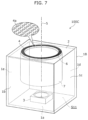
- FIG. 7 is a perspective view showing a structure of a sound reproduction device according to Embodiment 4.
- Sound reproduction device 100 C differs from sound reproduction device 100 B according to Embodiment 3 in that loudspeaker 3 is disposed such that the center of loudspeaker 3 coincides with center axis 5 . More specifically, loudspeaker 3 is disposed in an orientation in which the center axis of loudspeaker 3 in the sound emission direction passes through center axis 5 while being directed toward baffle 2 .
- loudspeaker 3 is disposed such that the center axis thereof passes through center axis 5 in sound reproduction device 100 C according to this embodiment, a distance between loudspeaker 3 and an annular inlet of space S 12 becomes the same at any position in a circumferential direction of the inlet.
- the sound pressures and phases of the plurality of sounds emitted from the plurality of through holes 4 a can be made to come closer to one another, and thus the effect of intensifying sound of a specific frequency band that has been emitted from the plurality of through holes 4 a on center axis 5 can be additionally enhanced.
- sound reproduction device 100 C can emit sound having directionality in the direction of center axis 5 with higher accuracy.
- loudspeaker 3 such that the center axis of loudspeaker 3 coincides with the center axis of baffle 2 in other embodiments.
- the distance between loudspeaker 3 and each of the plurality of through holes 4 a can be made the same.
- the sound pressures and phases of the plurality of sounds emitted from the plurality of through holes 4 a can be made to come closer to one another, and thus the effect of intensifying sound of a specific frequency band that has been emitted from each of the plurality of through holes 4 a on center axis 5 of ring-shaped area 4 can be additionally enhanced.
- the sound reproduction device in this case can emit sound of a specific frequency band, that has directionality in the direction of the center axis of the ring-shaped area with higher accuracy.
- cabinet 1 B according to this embodiment includes baffle 2 that is the same as that of cabinet 1 according to Embodiment 1, the structure is not limited thereto, and baffle 2 that is the same as that of cabinet 1 according to Embodiment 2 may be provided instead.
- FIG. 8 is a perspective view showing a structure of a sound reproduction device according to Embodiment 5.
- Sound reproduction device 100 D differs from sound reproduction device 100 according to Embodiment 1 in that opening portion 8 is provided in cabinet 1 D. Opening portion 8 is provided on side surface 1 c of cabinet 1 D. Side surface 1 c is an example of a second wall surface. It should be noted that opening portion 8 only needs to be provided on any of bottom surface 1 a and side surfaces 1 b to 1 e as wall surfaces different from that on which baffle 2 is provided in cabinet 1 D, and is not limited to being provided on side surface 1 c.
- sound emitted from loudspeaker 3 can be frequency-selected by the plurality of through holes 4 a provided in a toric shape so as to be reproduced after being separated into sound having directionality in the direction of center axis 5 and sound to be emitted from opening portion 8 .
- sound reproduction device 100 D can reproduce natural environment sound as if sound of murmuring of a river is heard from near the floor surface and sound of chirping of little birds is heard from near the ceiling. Therefore, a three-dimensional acoustic effect can be realized with a single loudspeaker.
- cabinet 1 according to Embodiment 2 or cabinet 1 B according to Embodiment 3 or 4 may include opening portion 8 provided in any of bottom surface 1 a and side surfaces 1 b to 1 e as wall surfaces different from that on which baffle 2 is provided, similar to this embodiment.
- cabinet 1 B of sound reproduction devices 100 B and 100 C according to Embodiments 3 and 4 includes opening portion 8 , other ends of inner wall 6 and outer wall 7 on the other side of ends connected to baffle 2 are provided at positions apart from the inner surface of cabinet 1 B and loudspeaker 3 .
- a gap is provided between the other ends of inner wall 6 and outer wall 7 and the inner surface of cabinet 1 B and loudspeaker 3 . Therefore, sound emitted from loudspeaker 3 to space S 11 inside cabinet 1 B enters space S 12 between inner wall 6 and outer wall 7 and is emitted to the outside from the plurality of through holes 4 a and also emitted to the outside from opening portion 8 .
- constituent elements described in the attached drawings and detailed descriptions may include, for the purpose of exemplifying the technique, constituent elements that are not essential for solving the problem.
- constituent elements that are not essential for solving the problem may include, for the purpose of exemplifying the technique, constituent elements that are not essential for solving the problem.
- the present disclosure is applicable to a sound reproduction device capable of emitting sound having directionality using a smaller number of loudspeakers.
Landscapes
- Health & Medical Sciences (AREA)
- Otolaryngology (AREA)
- Physics & Mathematics (AREA)
- Engineering & Computer Science (AREA)
- Acoustics & Sound (AREA)
- Signal Processing (AREA)
- Details Of Audible-Bandwidth Transducers (AREA)
- Obtaining Desirable Characteristics In Audible-Bandwidth Transducers (AREA)
Abstract
Description
-
- Japanese Unexamined Patent Application Publication No. 2006-101461
[PTL 2] - Japanese Unexamined Patent Application Publication No. 2015-154350
- Japanese Unexamined Patent Application Publication No. 2006-101461
Claims (9)
Applications Claiming Priority (5)
| Application Number | Priority Date | Filing Date | Title |
|---|---|---|---|
| JP2020-119882 | 2020-07-13 | ||
| JP2020119882 | 2020-07-13 | ||
| JP2020-144122 | 2020-08-28 | ||
| JP2020144122 | 2020-08-28 | ||
| PCT/JP2021/019645 WO2022014166A1 (en) | 2020-07-13 | 2021-05-24 | Sound reproduction device |
Publications (2)
| Publication Number | Publication Date |
|---|---|
| US20230125931A1 US20230125931A1 (en) | 2023-04-27 |
| US12200435B2 true US12200435B2 (en) | 2025-01-14 |
Family
ID=79555186
Family Applications (1)
| Application Number | Title | Priority Date | Filing Date |
|---|---|---|---|
| US17/918,032 Active 2041-12-10 US12200435B2 (en) | 2020-07-13 | 2021-05-24 | Sound reproduction device |
Country Status (4)
| Country | Link |
|---|---|
| US (1) | US12200435B2 (en) |
| JP (1) | JP7369943B2 (en) |
| CN (1) | CN115428471B (en) |
| WO (1) | WO2022014166A1 (en) |
Citations (4)
| Publication number | Priority date | Publication date | Assignee | Title |
|---|---|---|---|---|
| JPH07154889A (en) | 1993-11-30 | 1995-06-16 | Matsushita Electric Ind Co Ltd | Sound reproduction device |
| JP2006101461A (en) | 2004-09-30 | 2006-04-13 | Yamaha Corp | Stereophonic acoustic reproducing apparatus |
| US20120128190A1 (en) * | 2010-11-19 | 2012-05-24 | Apple Inc. | Gas filled speaker volume |
| JP2015154350A (en) | 2014-02-17 | 2015-08-24 | 株式会社デンソー | Stereophonic acoustic apparatus |
Family Cites Families (6)
| Publication number | Priority date | Publication date | Assignee | Title |
|---|---|---|---|---|
| JP2779602B2 (en) * | 1994-11-04 | 1998-07-23 | 株式会社ピィピィピィデザイン | A sound generator that forms a limited audible area |
| JP2007201976A (en) * | 2006-01-30 | 2007-08-09 | Sanyo Electric Co Ltd | Directional acoustic device |
| CN201054776Y (en) * | 2006-11-23 | 2008-04-30 | 峻扬实业股份有限公司 | Side reflection type horn box |
| JP5611068B2 (en) * | 2011-01-24 | 2014-10-22 | 株式会社オーディオテクニカ | Speaker enclosure and speaker system |
| WO2019107781A1 (en) * | 2017-11-28 | 2019-06-06 | Samsung Electronics Co., Ltd. | Loudspeaker and sound outputting apparatus having the same |
| CN207802375U (en) * | 2018-03-02 | 2018-08-31 | 广东得胜电子有限公司 | A kind of long-range loudspeaker |
-
2021
- 2021-05-24 CN CN202180028961.1A patent/CN115428471B/en active Active
- 2021-05-24 JP JP2022536160A patent/JP7369943B2/en active Active
- 2021-05-24 US US17/918,032 patent/US12200435B2/en active Active
- 2021-05-24 WO PCT/JP2021/019645 patent/WO2022014166A1/en not_active Ceased
Patent Citations (5)
| Publication number | Priority date | Publication date | Assignee | Title |
|---|---|---|---|---|
| JPH07154889A (en) | 1993-11-30 | 1995-06-16 | Matsushita Electric Ind Co Ltd | Sound reproduction device |
| JP2006101461A (en) | 2004-09-30 | 2006-04-13 | Yamaha Corp | Stereophonic acoustic reproducing apparatus |
| US20080247553A1 (en) | 2004-09-30 | 2008-10-09 | Yamaha Corporation | Stereophonic Sound Reproduction Device |
| US20120128190A1 (en) * | 2010-11-19 | 2012-05-24 | Apple Inc. | Gas filled speaker volume |
| JP2015154350A (en) | 2014-02-17 | 2015-08-24 | 株式会社デンソー | Stereophonic acoustic apparatus |
Non-Patent Citations (1)
| Title |
|---|
| International Search Report issued on Aug. 17, 2021 in International Patent Application No. PCT/JP2021/019645, with English translation. |
Also Published As
| Publication number | Publication date |
|---|---|
| WO2022014166A1 (en) | 2022-01-20 |
| JP7369943B2 (en) | 2023-10-27 |
| JPWO2022014166A1 (en) | 2022-01-20 |
| CN115428471A (en) | 2022-12-02 |
| US20230125931A1 (en) | 2023-04-27 |
| CN115428471B (en) | 2025-12-23 |
Similar Documents
| Publication | Publication Date | Title |
|---|---|---|
| US8280091B2 (en) | Dual compression drivers and phasing plugs for compression drivers | |
| KR102130365B1 (en) | Loudspeaker | |
| US20220386036A1 (en) | Omnidirectional loudspeaker and compression driver therefor | |
| EP2123106B1 (en) | Loudspeaker apparatus for radiating acoustic waves in a hemisphere | |
| CN109565628A (en) | Compression driver and phasing plug assembly therefor | |
| KR101900005B1 (en) | Loudspeaker magnet assembly | |
| US20110311087A1 (en) | Compression driver and horn structure | |
| KR20130037656A (en) | Array speaker system | |
| US11611823B2 (en) | Headphone | |
| US20180007463A1 (en) | Speaker device | |
| US8705786B2 (en) | Dynamic microphone unit and dynamic microphone | |
| US8428293B2 (en) | Speaker device | |
| JP2011101375A (en) | Improved loudspeaker | |
| KR102167420B1 (en) | Dynamic receiver with resonance protector for ear phone | |
| US20180242061A1 (en) | Speaker device | |
| KR101980163B1 (en) | Low profile loudspeaker suspension system | |
| US20180249243A1 (en) | Speaker device | |
| US12200435B2 (en) | Sound reproduction device | |
| US10183313B2 (en) | System for producing sound waves | |
| US10277978B2 (en) | Speaker device | |
| KR102670204B1 (en) | Loudspeaker and sound outputting apparatus having the same | |
| US20250344018A1 (en) | Loudspeaker device | |
| US20230217176A1 (en) | Speaker | |
| KR102543865B1 (en) | Speaker apparatus | |
| KR20250016305A (en) | Electro-acoustic transducers and headphones |
Legal Events
| Date | Code | Title | Description |
|---|---|---|---|
| FEPP | Fee payment procedure |
Free format text: ENTITY STATUS SET TO UNDISCOUNTED (ORIGINAL EVENT CODE: BIG.); ENTITY STATUS OF PATENT OWNER: LARGE ENTITY |
|
| AS | Assignment |
Owner name: PANASONIC INTELLECTUAL PROPERTY MANAGEMENT CO., LTD., JAPAN Free format text: ASSIGNMENT OF ASSIGNORS INTEREST;ASSIGNORS:KAKUHARI, ISAO;WASHIO, NOBUHIKO;SAKAI, TAKESHI;REEL/FRAME:062319/0753 Effective date: 20220907 |
|
| STPP | Information on status: patent application and granting procedure in general |
Free format text: DOCKETED NEW CASE - READY FOR EXAMINATION |
|
| STPP | Information on status: patent application and granting procedure in general |
Free format text: NON FINAL ACTION MAILED |
|
| STPP | Information on status: patent application and granting procedure in general |
Free format text: RESPONSE TO NON-FINAL OFFICE ACTION ENTERED AND FORWARDED TO EXAMINER |
|
| STPP | Information on status: patent application and granting procedure in general |
Free format text: NOTICE OF ALLOWANCE MAILED -- APPLICATION RECEIVED IN OFFICE OF PUBLICATIONS |
|
| STPP | Information on status: patent application and granting procedure in general |
Free format text: PUBLICATIONS -- ISSUE FEE PAYMENT RECEIVED |
|
| STPP | Information on status: patent application and granting procedure in general |
Free format text: PUBLICATIONS -- ISSUE FEE PAYMENT VERIFIED |
|
| STCF | Information on status: patent grant |
Free format text: PATENTED CASE |