US12192934B2 - Time synchronization method and apparatus, computer-readable medium, and electronic device - Google Patents
Time synchronization method and apparatus, computer-readable medium, and electronic device Download PDFInfo
- Publication number
- US12192934B2 US12192934B2 US17/675,531 US202217675531A US12192934B2 US 12192934 B2 US12192934 B2 US 12192934B2 US 202217675531 A US202217675531 A US 202217675531A US 12192934 B2 US12192934 B2 US 12192934B2
- Authority
- US
- United States
- Prior art keywords
- tsn
- time
- activation
- pdu session
- target
- Prior art date
- Legal status (The legal status is an assumption and is not a legal conclusion. Google has not performed a legal analysis and makes no representation as to the accuracy of the status listed.)
- Active, expires
Links
Images


Classifications
-
- H—ELECTRICITY
- H04—ELECTRIC COMMUNICATION TECHNIQUE
- H04J—MULTIPLEX COMMUNICATION
- H04J3/00—Time-division multiplex systems
- H04J3/02—Details
- H04J3/06—Synchronising arrangements
- H04J3/0635—Clock or time synchronisation in a network
- H04J3/0638—Clock or time synchronisation among nodes; Internode synchronisation
-
- H—ELECTRICITY
- H04—ELECTRIC COMMUNICATION TECHNIQUE
- H04J—MULTIPLEX COMMUNICATION
- H04J3/00—Time-division multiplex systems
- H04J3/02—Details
- H04J3/12—Arrangements providing for calling or supervisory signals
-
- H—ELECTRICITY
- H04—ELECTRIC COMMUNICATION TECHNIQUE
- H04W—WIRELESS COMMUNICATION NETWORKS
- H04W56/00—Synchronisation arrangements
- H04W56/001—Synchronization between nodes
- H04W56/0015—Synchronization between nodes one node acting as a reference for the others
-
- H—ELECTRICITY
- H04—ELECTRIC COMMUNICATION TECHNIQUE
- H04J—MULTIPLEX COMMUNICATION
- H04J3/00—Time-division multiplex systems
- H04J3/02—Details
- H04J3/06—Synchronising arrangements
- H04J3/0635—Clock or time synchronisation in a network
- H04J3/0638—Clock or time synchronisation among nodes; Internode synchronisation
- H04J3/0658—Clock or time synchronisation among packet nodes
-
- H—ELECTRICITY
- H04—ELECTRIC COMMUNICATION TECHNIQUE
- H04W—WIRELESS COMMUNICATION NETWORKS
- H04W76/00—Connection management
- H04W76/10—Connection setup
-
- H—ELECTRICITY
- H04—ELECTRIC COMMUNICATION TECHNIQUE
- H04W—WIRELESS COMMUNICATION NETWORKS
- H04W76/00—Connection management
- H04W76/30—Connection release
Definitions
- This application relates to the field of computer and communication technologies, and specifically, to a time synchronization method and apparatus, a computer-readable medium, and an electronic device.
- Time sensitive communication (TSC) in time sensitive networking (TSN) is introduced into R16 (Release16) of the 5th Generation mobile communication technology (5G) system, to enable the 5G system to support industrial automation and manufacturing applications of precision time control.
- Embodiments of this application provide a time synchronization method and apparatus, a computer-readable medium, and an electronic device, to control a time synchronization operation of a user equipment (UE).
- UE user equipment
- a time synchronization method including: receiving a time sensitive network (TSN) configuration creation request transmitted by an application function entity (AF), the TSN configuration creation request including an identifier of a target UE and first information used for indicating a TSN time synchronization trigger condition; and transmitting a TSN authorization request to a unified data management entity (UDM), the TSN authorization request being used for requesting the UDM to transmit, after confirming authorization, a TSN activation request including the first information to an access and mobility management function entity (AMF) registered by the target UE, to transmit, through the AMF, control signaling used for performing a TSN time synchronization operation to the target UE.
- TSN time sensitive network
- AF application function entity
- UDM unified data management entity
- AMF access and mobility management function entity
- a time synchronization method including: receiving a TSN authorization request, the TSN authorization request being used for requesting to update user subscription data of a target UE; and after confirming that update of the user subscription data of the target UE is authorized, transmitting, according to TSN activation subscription data included in the updated user subscription data, a TSN activation request to an AMF registered by the target UE, to instruct the AMF to transmit control signaling used for performing a TSN time synchronization operation to the target UE, the TSN activation request including first information used for indicating a TSN time synchronization trigger condition.
- a time synchronization method including: receiving a TSN activation request transmitted by a UDM, the TSN activation request including first information used for indicating a TSN time synchronization trigger condition; and transmitting control signaling to a target UE corresponding to a current AMF based on the first information, to control the target UE to perform a TSN time synchronization operation.
- a time synchronization method including: receiving control signaling transmitted by an AMF, the control signaling including first information used for indicating a TSN time synchronization trigger condition; and performing a TSN time synchronization operation based on the control signaling and the first information.
- a time synchronization apparatus including: a first receiving unit, configured to receive a time sensitive network (TSN) configuration creation request transmitted by an application function entity (AF), the TSN configuration creation request including an identifier of a target UE and first information used for indicating a TSN time synchronization trigger condition; and a first transmitting unit, configured to transmit a TSN authorization request to a unified data management entity (UDM), the TSN authorization request being used for requesting the UDM to transmit, after confirming authorization, a TSN activation request including the first information to an access and mobility management function entity (AMF) registered by the target UE, to transmit, through the AMF, control signaling used for performing a TSN time synchronization operation to the target UE.
- TSN time sensitive network
- AF application function entity
- AMF access and mobility management function entity
- a time synchronization apparatus including: a second receiving unit, configured to receive a TSN authorization request, the TSN authorization request being used for requesting to update user subscription data of a target UE; and a second transmitting unit, configured to, after confirming that update of the user subscription data of the target UE is authorized, transmit, according to TSN activation subscription data included in the updated user subscription data, a TSN activation request to an AMF registered by the target UE, to instruct the AMF to transmit control signaling used for performing a TSN time synchronization operation to the target UE, the TSN activation request including first information used for indicating a TSN time synchronization trigger condition.
- a time synchronization apparatus including: a third receiving unit, configured to receive a TSN activation request transmitted by a UDM, the TSN activation request including first information used for indicating a TSN time synchronization trigger condition; and a third transmitting unit, configured to transmit control signaling to a target UE corresponding to a current AMF based on the first information, to control the target UE to perform a TSN time synchronization operation.
- a time synchronization apparatus including: a fourth receiving unit, configured to receive control signaling transmitted by an AMF, the control signaling including first information used for indicating a TSN time synchronization trigger condition; and a processing unit, configured to perform a TSN time synchronization operation based on the control signaling and the first information.
- a computer-readable medium storing a computer program, the computer program, when executed by a processor, implementing the time synchronization method in the foregoing embodiments.
- an electronic device including: one or more processors; and a storage apparatus, configured to store one or more programs, the one or more programs, when executed by the one or more processors, causing the one or more processors to implement the time synchronization method according to the foregoing embodiments.
- an AF transmits a TSN configuration creation request to a network exposure function (NEF), the NEF transmits a TSN authorization request to a UDM, the UDM transmits a TSN activation request to an AMF, and the AMF transmits control signaling to a target UE, so that the target UE can be controlled to perform a TSN time synchronization operation based on a related condition triggered by the TSN, to effectively control a time synchronization operation of one UE or a group of UEs.
- NEF network exposure function
- FIG. 1 is a schematic diagram of a time synchronization procedure.
- FIG. 2 is a schematic architectural diagram of a 5G system supporting time synchronization in external time domain.
- FIG. 3 is a schematic architectural diagram of a time synchronization requirement proposed in the 5G R17 standard.
- FIG. 4 is a flowchart of a time synchronization method according to an embodiment of this application.
- FIG. 5 is a flowchart of a time synchronization method according to an embodiment of this application.
- FIG. 6 is a flowchart of a time synchronization method according to an embodiment of this application.
- FIG. 7 is a flowchart of a time synchronization method according to an embodiment of this application.
- FIG. 8 is a flowchart of a UDM performing control to perform a TSN time synchronization activation operation according to an embodiment of this application.
- FIG. 9 is a flowchart of a UDM performing control to perform a TSN time synchronization deactivation operation according to an embodiment of this application.
- FIG. 10 is a flowchart of an AMF performing control to perform a TSN time synchronization activation operation according to an embodiment of this application.
- FIG. 11 is a flowchart of an AMF performing control to perform a TSN time synchronization deactivation operation according to an embodiment of this application.
- FIG. 12 is a flowchart of a UE performing control to perform a TSN time synchronization activation operation according to an embodiment of this application.
- FIG. 13 is a flowchart of a UE performing control to perform a TSN time synchronization deactivation operation according to an embodiment of this application.
- FIG. 14 is a flowchart of an old AMF transmitting context information to a new AMF in a procedure in which a UE registers the new AMF.
- FIG. 15 is a flowchart of an old AMF transmitting context information to a new AMF during network switching.
- FIG. 16 is a flowchart of an NEF performing control to perform a TSN time synchronization activation operation according to an embodiment of this application.
- FIG. 17 is a flowchart of an NEF performing control to perform a TSN time synchronization deactivation operation according to an embodiment of this application.
- FIG. 18 is a flowchart of an NEF performing control to perform a TSN time synchronization activation operation according to an embodiment of this application.
- FIG. 19 is a flowchart of an NEF performing control to perform a TSN time synchronization deactivation operation according to an embodiment of this application.
- FIG. 20 is a block diagram of a time synchronization apparatus according to an embodiment of this application.
- FIG. 21 is a block diagram of a time synchronization apparatus according to an embodiment of this application.
- FIG. 22 is a block diagram of a time synchronization apparatus according to an embodiment of this application.
- FIG. 23 is a block diagram of a time synchronization apparatus according to an embodiment of this application.
- FIG. 24 is a schematic structural diagram of a computer system adapted to implement an electronic device according to an embodiment of this application.
- module may refer to a software module, a hardware module, or a combination thereof.
- a software module e.g., computer program
- a hardware module may be implemented using processing circuitry and/or memory.
- Each module can be implemented using one or more processors (or processors and memory).
- a processor or processors and memory
- each module can be part of an overall module that includes the functionalities of the module.
- a module is configured to perform functions and achieve goals such as those described in this disclosure, and may work together with other related modules, programs, and components to achieve those functions and goals.
- the clock offset measurement may be implemented by using a precision time protocol (PTP, defined by an Institute of Electrical and Electronics Engineers (IEEE) 1588 protocol)/generalized precision time protocol (gPTP, defined by an IEEE 802.1AS protocol) message and algorithm.
- PTP precision time protocol
- IEEE Institute of Electrical and Electronics Engineers
- gPTP generalized precision time protocol
- a time data receiving party (which is assumed herein to be an end station (ES, being a device connected to a local area network or metropolitan area network, to serve as a source and/or destination for traffic borne on the local area network or metropolitan area network)) measures, based on a method defined by an IEEE 1588v2 protocol, a clock offset (abbreviated to 0 below) and a delay (abbreviated to D below) relative to a TSN clock domain A through a received data packet.
- ES end station
- D delay
- a and B are intermediate variables; t 1 is a time value of the TSN clock domain A carried in a Sync (synchronization packet) message or Follow_up (follow_up packet) message; t 2 and t 3 are time values of local clocks of the ES, t 2 indicates a time value of a local clock corresponding to a case that the ES receives the Sync message, and t 3 indicates a time value of a local clock corresponding to a case that the ES transmits a Delay_Req (delay request packet) message; D indicates a transmission delay value of transmitting the Sync message from the TSN clock domain A to the ES; and t 4 is a time value of the TSN clock domain A corresponding to a case that the TSN clock domain A receives the Delay_Req message.
- the ES may use any one of the parameters to set its time, thereby implementing time synchronization between a local time of the ES and a master clock of the TSN clock domain A, which is an algorithm of performing time synchronization between the ES and the master clock of the TSN clock domain A.
- the time of the ES and the time of the master clock of the clock domain A may have an increasingly large difference.
- the foregoing measurement procedure may be periodically repeatedly performed, to ensure that the time of the ES and the time of the master clock of the clock domain A have a difference within a range.
- the master clock may periodically transmit a Sync (or optionally, further transmit Follow_up) message whose destination address is a multicast address, and does not perform bidirectional signaling interaction with the ES anymore, and a network transmitting these messages precisely calculates a transmission delay of the Sync (or optionally, further including Follow_up) message from the master clock to the ES.
- the ES may implement time synchronization with the master clock according to the delay provided by the network and a time value of the master clock on the Sync (or optionally, further including Follow_up) message.
- FIG. 2 is a schematic architectural diagram of a 5G system supporting time synchronization in external time domain.
- the 5G system as a TSN bridge is integrated in a TSN system.
- This “logic” TSN bridge includes a TSN translator, used for interaction of a user plane between the TSN system and the 5G system.
- 5GS (5G system) TSN translator functionality includes a DS-TT (device side TSN translator) and an NW-TT (network TSN translator).
- a UE in the 5G system is connected to one or more ESs in a TSN data network (DN) outside the 5G system by the DS-TT.
- a user plane function (UPF) is connected to one or more ESs in the TSN DN by the NW-TT.
- the entire end-to-end 5G system may be considered as an IEEE 802.1AS time aware system.
- FIG. 2 there are two time synchronization domains being respectively a 5G time domain and a TSN time domain.
- the 5G system has its own time system (for example, GPS (Global Positioning System) time), and in FIG. 2 , a 5G GM (5G Grand Master) is used to indicate a clock domain of the 5G system (that is, 5G time domain).
- GPS Global Positioning System
- the gNB in FIG. 2 indicates a 5G base station.
- Devices in the 5G system are all synchronized to the 5G clock domain.
- the devices in the 5G system include: a UPF, an SMF, a UE, a DS-TT, an NW-TT, an NG RAN (NG Radio Access Network, 5G radio access network), and the like, where an NG interface is an interface between the radio access network and a 5G core network.
- a clock source of the external TSN Time Domain is outside the UPF.
- the UE side device namely the ES of the TSN is connected to the UE by the DS-TT, accesses a 5G network, and then accesses an external TSN network through the UPF and the NW-TT on the UPF, to perform time synchronization with the clock source of the TSN.
- a time synchronization message may be transmitted by the TSN GM through downlink (DL) data, that is, through a user plane of the UE, and the downlink data including the time synchronization message of the TSN GM first reaches the NW-TT/UPF, enters the 5G system, then reaches the UE and the DS-TT thereof, and finally reaches the UE side ES.
- DL downlink
- the TSN GM identifies a current time thereof on an originTimestamp field of the time synchronization message transmitted by the TSN GM. While the user plane of the UE transfers this time synchronization message, the NW-TT marks (labels) this time synchronization message with a receiving time of receiving this downlink data, and a CorrectionField field value in this data packet is updated to an original CorrectionField field value plus a transmission delay value between the NW-TT and an Ethernet bridge port transmitting this message to the NW-TT, where the transmission delay between the NW-TT and this port may be obtained through the method shown in FIG. 1 or in another manner.
- the receiving time added by the NW-TT to the downlink data is subtracted from the current time thereof, thereby obtaining a transmission delay value of this time synchronization message in the entire 5G system.
- This delay value and the previous transmission time (on the CorrectionField field of the received time synchronization message) from the TSN master clock to the NW-TT are added, to obtain an updated transmission delay value, and the CorrectionField field of the time synchronization message (that is, a total transmission delay of this message) is marked with this updated transmission delay value.
- the receiving time with which the NW-TT previously performs marking is deleted. Then, this modified time synchronization message is transmitted to the ES.
- the ES may obtain, by directly adding the delay value on the time synchronization message to the transmission delay between the DS-TT and the ES (the transmission delay between the ES and the DS-TT may be obtained through the method shown in FIG. 1 or in another manner) according to the delay value with which the DS-TT marks the time synchronization message (that is, the CorrectionField field value on the time synchronization message), a total transmission delay of this time synchronization message from the TSN master clock to the ES, a calculated time value may be obtained by adding this total transmission delay to the originTimestamp field value on the time synchronization message, and then a clock thereof is set to this calculated time value, thereby implementing time synchronization between the UE side ES and the TSN GM.
- FIG. 3 is a schematic architectural diagram of a time synchronization requirement proposed in the 5G R17 standard.
- the UE side ES needs to synchronize time to the TSN GM on the UPF/NW-TT side.
- a TSN GM that is, a master clock of a TSN
- an ES on a UPF/NW-TT side and an ES on another UE need to perform time synchronization with the TSN GM on this UE1 side. That is, the TSN GM transmits a time synchronization message through an uplink method by using a user plane of the UE1, and then the time synchronization message reaches the UPF.
- the time synchronization message is transmitted to the TSN ES through the NW-TT.
- the UPF transmits the time synchronization message to the UE2 through downlink data of the UE2, and then transmits the time synchronization message to the TSN ES through the DS-TT of the UE2.
- the DS-TT of the UE1 records a receiving time in which the UE1 receives an uplink (UL) data packet transmitted by the TSN GM and including the time synchronization message, and marks the UL time synchronization message data packet with the receiving time; meanwhile, a CorrectionField field value in this data packet is updated to an original CorrectionField field value plus a transmission delay value between the DS-TT and the TSN GM, where the transmission delay between the DS-TT and the TSN GM may be obtained through the method shown in FIG. 1 or in another manner.
- UL uplink
- the NW-TT subtracts, from the time in which the NW-TT receives this UL data packet, the receiving time with which the DS-TT of the UE1 marks the packet, to obtain a transmission delay value of the entire UL data packet in the 5G system, and this delay value and the previous transmission time from the TSN GM to the UE1 DS-TT (on the CorrectionField field of the received time synchronization message) are added, to obtain an updated transmission delay value; and marks the CorrectionField field of this UL synchronization message data packet with the updated transmission delay value, simultaneously deletes a receiving time label with which the DS-TT of the UE1 performs marking, and then transmits this UL data packet to TSN ESs connected to the right NW-TT (including TSN ESs of the TSN time domain 1 and the TSN time domain 2).
- a TSN ES connected to the right NW-TT may obtain, by directly adding the delay value on the time synchronization message to the transmission delay between the NW-TT and the TSN ES according to the delay value with which the NW-TT marks the time synchronization message (that is, the CorrectionField field value on the time synchronization message), a total transmission delay of this synchronization message from the TSN GM to the TSN ES connected to the NW-TT, a calculated time value may be obtained by adding this total transmission delay to the originTimestamp field value on the time synchronization message, and then a clock thereof is set to this calculated time value, thereby implementing time synchronization between the TSN ES on the NW-TT side and the TSN GM on the UE1 side.
- the UPF When the time synchronization message needs to be transmitted to the TSN ES of the UE2, the UPF simultaneously transmits the time synchronization message to the UE2 through the user plane of the UE2, and then the time synchronization message reaches the DS-TT of the UE2.
- the DS-TT of the UE2 subtracts, from the time in which the DS-TT receives the downlink data packet including the time synchronization message, the receiving time with which the DS-TT of the UE1 marks the downlink synchronization message data packet, to obtain a transmission delay value of the entire data packet including the time synchronization message in the 5G system, and this transmission delay value and the previous transmission time from the TSN GM to the UE1 DS-TT (on the CorrectionField field of the received time synchronization message) are added, to obtain an updated transmission delay value; and marks the CorrectionField field of this DL data packet including the time synchronization message with the updated transmission delay value, simultaneously deletes a receiving time label with which the DS-TT of the UE1 performs marking, and then transmits this DL data packet to the TSN ES on the UE2 DS-TT.
- the TSN ES on the UE2 DS-TT may implement time synchronization with the T
- a solid arrow indicates gPTP by ingress DS-TT; and a dashed arrow indicates locally-switched gPTP by ingress DS-TT.
- the DS-TT of the UE1 in FIG. 3 is simultaneously connected to the TSN GM Domain 1 and the TSN GM Domain 2, but it may be likely that the DS-TT of the UE1 is connected to the TSN GM Domain 1 and a DS-TT of a UE X is connected to the TSN GM Domain 2.
- the DS-TT of the UE2 in FIG. 3 is connected to only one End Station of a TSN GM Domain, but it may be likely that the DS-TT of the UE2 may be connected to a plurality of End Stations and all the End Stations respectively correspond to different TSN GM Domains.
- a DS-TT of a UE may be connected to a GM or an End Station of one or more different TSN GM Domains; and a DS-TT of a UE may be connected to a GM of a TSN GM Domain X and simultaneously connected to an End Station of a TSN GM Domain Y, or be in another connection manner.
- an embodiment of this application proposes that an AF transmits a TSN configuration creation request to an NEF, the NEF transmits a TSN authorization request to a UDM, the UDM transmits a TSN activation request to an AMF, the AMF transmits control signaling to a target UE, to trigger the UE to perform a TSN time synchronization activation or deactivation operation; meanwhile, a time requirement for the UE to perform TSN time synchronization may be added to a trigger condition.
- FIG. 4 is a flowchart of a time synchronization method according to an embodiment of this application.
- the time synchronization method may be performed by an NEF.
- the time synchronization method includes at least step S 410 and step S 420 .
- a detailed description is as follows:
- Step S 410 Receive a time sensitive network (TSN) configuration creation request transmitted by an application function entity (AF), the TSN configuration creation request including an identifier of a target UE and first information used for indicating a TSN time synchronization trigger condition.
- TSN time sensitive network
- the target UE is a UE that needs to perform TSN time synchronization.
- the first information used for indicating the TSN time synchronization trigger condition may include the following information: a TSN clock domain identifier, first field information used for indicating uplink TSN synchronization or downlink TSN synchronization, second field information used for indicating an activation operation or a deactivation operation, network slice information, and a data network name.
- the TSN clock domain identifier is used for identifying a TSN clock domain to which synchronization needs to be performed;
- the first field information is used for indicating uplink TSN synchronization or downlink TSN synchronization, for example, a first value of the first field information indicates uplink TSN synchronization and a second value of the first field information indicates downlink TSN synchronization;
- the second field information is used for indicating an activation operation or a deactivation operation, for example, a first value of the second field information indicates an activation operation and a second value of the second field information indicates a deactivation operation;
- the network slice information may be Single Network Slice Selection Assistance Information (S-NSSAI), used for identifying a network slice; and the data network name is abbreviated to DNN.
- S-NSSAI Single Network Slice Selection Assistance Information
- the TSN activation time information is used for indicating that a TSN time synchronization operation is performed immediately, or used for indicating that a TSN time synchronization operation is performed after a predetermined time, or used for indicating that a TSN time synchronization operation is performed at a designated time point; and when the first information does not include the TSN activation time information, the first information is used for indicating that a TSN time synchronization operation is performed immediately.
- Step S 420 Transmit a TSN authorization request to a UDM, the TSN authorization request being used for requesting the UDM to transmit, after confirming authorization, a TSN activation request including the first information to an access and mobility management function entity (AMF) registered by the target UE, to transmit, through the AMF, control signaling used for performing a TSN time synchronization operation to the target UE.
- AMF access and mobility management function entity
- the identifier of the target UE may be translated from an external identifier into a network identifier, and when the identifier of the target UE includes an external identifier of a single UE, the external identifier of the single UE is translated into a network identifier of the single UE; and when the identifier of the target UE includes an external group identifier corresponding to a plurality of UEs, the external group identifier is translated into a network identifier list of the plurality of UEs.
- the external identifier of the UE may be a mobile phone number.
- the network identifier of the UE may be an IMSI (International Mobile Subscriber Identity), a GPSI (Generic Public Subscription Identifier), or an SUPI (Subscription Permanent Identifier).
- the NEF when transmitting the TSN authorization request to the UDM, the NEF needs to transmit the TSN authorization request to the UDM for each UE in the network identifier list.
- FIG. 4 The embodiment shown in FIG. 4 is described from the perspective of the NEF, and a time synchronization method of an embodiment of this application is described below from the perspective of a UDM with reference to FIG. 5 .
- the time synchronization method may be performed by a UDM, and includes at least the following step S 510 and step S 520 .
- a detailed description is as follows:
- Step S 510 Receive a TSN authorization request, the TSN authorization request being used for requesting to update user subscription data of a target UE.
- the UDM may receive the TSN authorization request transmitted by an NEF, and for a procedure in which the NEF transmits the TSN authorization request, reference may be made to the technical solution of the foregoing embodiments.
- the UDM may determine whether to allow the NEF to request to add or modify subscription data of a UE (target UE); if yes, the UE subscription data may be added.
- the UE subscription data may include a TSN clock domain identifier, first field information used for indicating uplink TSN synchronization or downlink TSN synchronization, second field information used for indicating an activation operation or a deactivation operation, network slice information, and a data network name. Then, the UDM may perform TSN activation and deactivation operations on the target UE based on information about this UE subscription data.
- Step S 520 After confirming that update of the user subscription data of the target UE is authorized, transmit, according to TSN activation subscription data included in the updated user subscription data, a TSN activation request to an AMF registered by the target UE, to instruct the AMF to transmit control signaling used for performing a TSN time synchronization operation to the target UE, the TSN activation request including first information used for indicating a TSN time synchronization trigger condition.
- the first information included in the TSN activation request comes from the TSN authorization request transmitted by the NEF, but an initial source is a TSN configuration creation request transmitted by an AF. Similar to the foregoing embodiments, the target UE is a UE that needs to perform TSN time synchronization.
- the first information may include the following information: a TSN clock domain identifier, first field information used for indicating uplink TSN synchronization or downlink TSN synchronization, second field information used for indicating an activation operation or a deactivation operation, network slice information, and a data network name.
- the UDM may control, by controlling an occasion of transmitting the TSN activation request to the AMF registered by the target UE, the time of performing the TSN time synchronization operation by the target UE. Details are as follows:
- TSN activation time information included in the TSN authorization request indicates that a TSN time synchronization operation is performed immediately or the TSN authorization request does not include the TSN activation time information, immediately transmit the TSN activation request to the AMF registered by the target UE.
- That the TSN authorization request does not include the TSN activation time information may include the following several embodiments: A case is that when transmitting the TSN authorization request to the UDM, the NEF has performed time control. In one embodiment, none of the UDM, the AMF, and the target UE needs to perform time control, and when receiving the TSN authorization request, the UDM immediately transmits the TSN activation request to the AMF registered by the target UE. Another case is that none of the NEF, the UDM, the AMF, and the target UE performs time control.
- the NEF after receiving the TSN configuration creation request transmitted by the AF and performing processing (for example, performing translation on the identifier of the target UE), the NEF directly transmits the TSN authorization request to the UDM, and when receiving the TSN authorization request, the UDM immediately transmits the TSN activation request to the AMF registered by the target UE.
- TSN activation time information included in the TSN authorization request indicates that a TSN time synchronization operation is performed after a predetermined time
- the UDM transmits, after the predetermined time after receiving the TSN authorization request, the TSN activation request to the AMF registered by the target UE.
- TSN activation time information included in the TSN authorization request indicates that a TSN time synchronization operation is performed at a designated time point
- the UDM transmits, when a current time reaches the designated time point, the TSN activation request to the AMF registered by the target UE.
- TSN activation time information included in the TSN authorization request indicates that a TSN time synchronization operation is performed after a predetermined time but a current time has exceeded the designated time point
- the UDM immediately transmits the TSN activation request to the AMF registered by the target UE.
- the UDM may alternatively not control the occasion on which the target UE performs the TSN time synchronization operation. That is, after receiving the TSN authorization request, the UDM immediately generates the TSN activation request, and transmits the TSN activation request to the AMF registered by the target UE.
- the TSN activation request transmitted by the UDM to the AMF may include the TSN activation time information, and the TSN activation time information comes from the TSN authorization request transmitted by the NEF to the UDM, but an initial source is a TSN configuration creation request transmitted by an AF to an NEF.
- one target UE may register a plurality of AMFs with the UDM, such as a first AMF whose access network conforms to a 3GPP standard (for example, 2G, 3G, 4G, or 5G), and a second AMF whose access network does not conform to a 3GPP standard (for example, Wi-Fi).
- a 3GPP standard for example, 2G, 3G, 4G, or 5G
- a second AMF whose access network does not conform to a 3GPP standard (for example, Wi-Fi).
- the UDM when transmitting the TSN activation request to the first AMF registered by the target UE, the UDM may first transmit the TSN activation request to the first AMF whose access network conforms to the 3GPP standards, and when an activation response fed back by the first AMF indicates unsuccessful activation or a protocol data unit (PDU) session registration message fed back by an SMF for the first target UE is not received, then transmit the TSN activation request to the second AMF whose access network does not conform to the 3GPP standards.
- PDU protocol data unit
- the UDM may simultaneously transmit the TSN activation request to the plurality of AMFs, and when an activation response fed back by each of the plurality of AMFs indicates unsuccessful activation or a PDU session registration message fed back by an SMF for the first target UE is not received in a set time, transmit the TSN activation request to the plurality of AMFs again.
- FIG. 5 The embodiment shown in FIG. 5 is described from the perspective of the UDM, and a time synchronization method of an embodiment of this application is described below from the perspective of an AMF with reference to FIG. 6 .
- the time synchronization method may be performed by an AMF, and includes at least the following step S 610 and step S 620 .
- a detailed description is as follows:
- Step S 610 Receive a TSN activation request transmitted by a UDM, the TSN activation request including first information used for indicating a TSN time synchronization trigger condition.
- the first information included in the TSN activation request comes from the TSN authorization request transmitted by the NEF to the UDM, but an initial source is a TSN configuration creation request transmitted by an AF to an NEF.
- the first information may include the following information: a TSN clock domain identifier, first field information used for indicating uplink TSN synchronization or downlink TSN synchronization, second field information used for indicating an activation operation or a deactivation operation, network slice information, and a data network name.
- Step S 620 Transmit control signaling to a target UE corresponding to a current AMF based on the first information, to control the target UE to perform a TSN time synchronization operation.
- the target UE corresponding to the current AMF may be a target UE in signaling connection to the current AMF, or a target UE previously establishing signaling connection to the current AMF.
- the AMF when transmitting control signaling to the target UE corresponding to the current AMF, the AMF needs to first detect whether signaling connection between the target UE and the network is in the connection management idle state (CM-IDLE state), and when detecting that the target UE is in the connection management idle state, the AMF needs to initiate a network triggered service request procedure, to establish signaling connection to the target UE; and when detecting that the target UE is in a connection management connected state (CM-CONNECTED state), the AMF transmits control signaling to the target UE corresponding to the current AMF.
- CM-IDLE state connection management idle state
- CM-CONNECTED state connection management connected state
- the control signaling transmitted by the AMF to the corresponding target UE may be a PDU session establishment instruction; and when second field information indicates a deactivation operation, the control signaling transmitted by the AMF to the corresponding target UE may be a PDU session release instruction or PDU session modification instruction.
- CM (connection management) states of a UE include: CM-IDLE (that is, idle state) and CM-CONNECTED (that is, connected state), and the CM states reflect signaling connection characteristics of the UE.
- CM-IDLE In the idle state (CM-IDLE), no NAS (Non-Access Stratum) signaling connection exists between the UE and the network, for example, neither Radio Resource Control (RRC) connection nor N1-AMF connection is included; and in the connected state (CM-CONNECTED), NAS signaling connection including RRC connection and N1-AMF connection exists between the UE and the network.
- RRC Radio Resource Control
- the first information included in the TSN activation request may indicate an activation operation, or may indicate a deactivation operation, and detailed descriptions are made below for such two embodiments as activation and deactivation respectively:
- the control signaling transmitted by the AMF to the corresponding target UE is a PDU session establishment instruction, and transmitting manners may include the following examples:
- the AMF immediately transmits a PDU session establishment instruction to the target UE, to instruct the target UE to establish a PDU session.
- the AMF transmits a PDU session establishment instruction to the target UE after the predetermined time after receiving the TSN activation request, to instruct the target UE to establish a PDU session.
- the original AMF may transmit context information of TSN synchronization activation to the new AMF, to cause the new AMF to transmit a PDU session establishment instruction to the target UE after a TSN remaining activation time is reached.
- the context information includes: a TSN clock domain identifier, first field information used for indicating uplink TSN synchronization or downlink TSN synchronization, second field information used for indicating an activation operation, network slice information, a data network name, and TSN activation time information.
- a time value indicated by the TSN activation time information is a TSN remaining activation time
- the TSN remaining activation time is a difference between the predetermined time and an elapsed time (a time that has elapsed after the TSN activation request is received by the original AMF).
- the original AMF may transmit context information of TSN synchronization activation to the new AMF through a UE context transfer message (Namf_Communication_UEContextTransfer); and when a new AMF is selected for the target UE in a network switching procedure, the original AMF may transmit the context information of TSN synchronization activation to the new AMF through a create UE context request (Namf_Communication_CreateUEContext Request).
- the AMF transmits a PDU session establishment instruction to the target UE when the current time reaches the designated time point, to instruct the target UE to establish a PDU session.
- the original AMF may transmit context information of TSN synchronization activation to the new AMF, to cause the new AMF to transmit a PDU session establishment instruction to the target UE when the current time reaches the designated time point.
- the context information includes: a TSN clock domain identifier, first field information used for indicating uplink TSN synchronization or downlink TSN synchronization, second field information used for indicating an activation operation, network slice information, a data network name, and TSN activation time information.
- a value indicated by the TSN activation time information is the designated time point.
- the original AMF may transmit context information of TSN synchronization activation to the new AMF through a UE context transfer message (Namf_Communication_UEContextTransfer); and when a new AMF is selected for the target UE in a network switching procedure, the original AMF may transmit the context information of TSN synchronization activation to the new AMF through a create UE context request (Namf_Communication_CreateUEContext Request).
- the AMF When the first information includes TSN activation time information, the TSN activation time information indicates that the TSN time synchronization operation is performed at a designated time point, and the second field information indicates an activation operation, but the current time has exceeded the designated time point, the AMF immediately transmits a PDU session establishment instruction to the target UE, to instruct the target UE to establish a PDU session.
- the AMF When the first information does not include TSN activation time information and the second field information indicates an activation operation, the AMF immediately transmits a PDU session establishment instruction to the target UE, to instruct the target UE to establish a PDU session.
- That the first information in the TSN activation request does not include the TSN activation time information may include the following several embodiments:
- a case is that when transmitting the TSN authorization request to the UDM, the NEF has performed time control. In one embodiment, none of the UDM, the AMF, and the target UE needs to perform time control; and when receiving the TSN authorization request, the UDM immediately transmits the TSN activation request to the AMF registered by the target UE, and after receiving the TSN activation request, the AMF immediately transmits control signaling to the corresponding target UE.
- Another case is that the NEF does not perform time control, while the UDM performs time control.
- the UDM decides, according to the TSN activation time information included in the received TSN authorization request, when to transmit the TSN activation request to the AMF, and after receiving the TSN activation request, the AMF immediately transmits control signaling to the corresponding target UE.
- the AMF immediately transmits control signaling to the corresponding target UE.
- Sill another case is that none of the NEF, the UDM, the AMF, and the target UE performs time control.
- the NEF after receiving the TSN configuration creation request transmitted by the AF and performing processing (for example, performing translation on the identifier of the target UE), the NEF directly transmits the TSN authorization request to the UDM; and when receiving the TSN authorization request, the UDM immediately transmits the TSN activation request to the AMF registered by the target UE, and after receiving the TSN activation request, the AMF immediately transmits control signaling to the corresponding target UE.
- the PDU session establishment instruction transmitted by the AMF may include the following parameters: a TSN clock domain identifier, first field information used for indicating uplink TSN synchronization or downlink TSN synchronization, second field information used for indicating an activation operation, network slice information, and a data network name. These parameters and values of the parameters come from the first information included in the TSN activation request received by the AMF.
- the AMF may alternatively transmit the PDU session establishment instruction including the TSN activation time information to the corresponding target UE, and the value of the TSN activation time information comes from the first information included in the TSN activation request received by the AMF.
- the AMF does not perform a time control operation, but transmits the PDU session establishment instruction including the TSN activation time information to the target UE, to instruct the target UE to initiate a PDU session establishment procedure at a corresponding time.
- the control signaling transmitted by the AMF to the corresponding target UE is a PDU session release instruction or PDU session modification instruction, and transmitting manners may include the following examples:
- the AMF immediately transmits a PDU session release instruction or PDU session modification instruction to the target UE, to instruct the target UE to initiate a PDU session release procedure or PDU session modification procedure.
- the AMF transmits a PDU session release instruction or PDU session modification instruction to the target UE after the predetermined time after receiving the TSN activation request, to instruct the target UE to initiate a PDU session release procedure or PDU session modification procedure.
- the original AMF may transmit context information of TSN synchronization activation to the new AMF, to cause the new AMF to transmit a PDU session release instruction or PDU session modification instruction to the target UE after a TSN remaining activation time is reached.
- the context information includes: a TSN clock domain identifier, first field information used for indicating uplink TSN synchronization or downlink TSN synchronization, second field information used for indicating a deactivation operation, network slice information, a data network name, and TSN activation time information.
- a time value indicated by the TSN activation time information is a TSN remaining activation time
- the TSN remaining activation time is a difference between the predetermined time and an elapsed time (a time that has elapsed after the TSN activation request is received by the original AMF).
- the AMF transmits a PDU session release instruction or PDU session modification instruction to the target UE when the current time reaches the designated time point, to instruct the target UE to initiate a PDU session release procedure or PDU session modification procedure.
- the original AMF may transmit context information of TSN synchronization activation to the new AMF, to cause the new AMF to transmit a PDU session release instruction or PDU session modification instruction to the target UE when the current time reaches the designated time point.
- the context information includes: a TSN clock domain identifier, first field information used for indicating uplink TSN synchronization or downlink TSN synchronization, second field information used for indicating a deactivation operation, network slice information, a data network name, and TSN activation time information.
- a time value indicated by the TSN activation time information is the designated time point.
- the AMF When the first information includes TSN activation time information, the TSN activation time information indicates that the TSN time synchronization operation is performed at a designated time point, and the second field information indicates a deactivation operation, but the current time has exceeded the designated time point, the AMF immediately transmits a PDU session release instruction or PDU session modification instruction to the target UE, to instruct the target UE to initiate a PDU session release procedure or PDU session modification procedure.
- the first information does not include TSN activation time information and the second field information indicates a deactivation operation, immediately transmit a PDU session release instruction or PDU session modification instruction to the target UE, to instruct the target UE to initiate a PDU session release procedure or a PDU session modification procedure.
- the PDU session release instruction or PDU session modification instruction may include the following parameters: a TSN clock domain identifier, first field information used for indicating uplink TSN synchronization or downlink TSN synchronization, second field information used for indicating a deactivation operation, network slice information, and a data network name. These parameters and values of the parameters come from the first information.
- the target UE after the AMF transmits the PDU session release instruction or PDU session modification instruction to the corresponding target UE, the target UE initiates the PDU session release procedure or PDU session modification procedure.
- the AMF may alternatively directly initiate the PDU session release procedure or modification procedure. Details are as follows:
- the AMF immediately initiates a PDU session release procedure or PDU session modification procedure.
- the PDU session release procedure or PDU session modification procedure refers to a PDU session release procedure or PDU session modification procedure related to the target UE.
- the TSN activation time information indicates that the TSN time synchronization operation is performed after a predetermined time
- the second field information indicates a deactivation operation
- the AMF initiates a PDU session release procedure or PDU session modification procedure after the predetermined time after receiving the TSN activation request.
- the original AMF may transmit context information of TSN synchronization activation to the new AMF, to cause the new AMF to initiate a PDU session release procedure or PDU session modification procedure after a TSN remaining activation time is reached.
- the context information includes: a TSN clock domain identifier, first field information used for indicating uplink TSN synchronization or downlink TSN synchronization, second field information used for indicating a deactivation operation, network slice information, a data network name, and TSN activation time information.
- a time value indicated by the TSN activation time information is a TSN remaining activation time
- the TSN remaining activation time is a difference between the predetermined time and an elapsed time (a time that has elapsed after the TSN activation request is received by the original AMF).
- the TSN activation time information indicates that the TSN time synchronization operation is performed at a designated time point
- the second field information indicates a deactivation operation
- the AMF initiates a PDU session release procedure or PDU session modification procedure when the current time reaches the designated time point.
- the original AMF may transmit context information of TSN synchronization activation to the new AMF, to cause the new AMF to initiate a PDU session release procedure or PDU session modification procedure after the current time reaches the designated time point.
- the context information includes: a TSN clock domain identifier, first field information used for indicating uplink TSN synchronization or downlink TSN synchronization, second field information used for indicating a deactivation operation, network slice information, a data network name, and TSN activation time information.
- a time value indicated by the TSN activation time information is the designated time point.
- the TSN activation time information indicates that the TSN time synchronization operation is performed at a designated time point
- the second field information indicates a deactivation operation, but the current time has exceeded the designated time point
- the AMF immediately initiates a PDU session release procedure or PDU session modification procedure.
- the AMF When the first information does not include TSN activation time information and the second field information indicates a deactivation operation, the AMF immediately initiates a PDU session release procedure or a PDU session modification procedure.
- the initiating, by the AMF, a PDU session release procedure or PDU session modification procedure may be generating PDU session update information.
- the PDU session update information includes an identifier of a to-be-deactivated target TSN clock domain.
- the AMF transmits the PDU session update information to an SMF, to cause the SMF to instruct a user plane function entity to stop forwarding TSN time synchronization data of the target TSN clock domain to the target UE.
- a PDU session established by the UE supports a time synchronization operation of a plurality of TSN clock domains.
- the AMF may initiate a PDU session modification procedure; or when a to-be-deactivated target TSN clock domain, network slice information, and a data network name that are included in the first information are respectively matched with a TSN clock domain, network slice information, and a data network name of the PDU session established by the target UE and the to-be-deactivated target TSN clock domain is a last TSN clock domain in the PDU session, the AMF may initiate a PDU session modification procedure; or when a to-be-deactivated target TSN clock domain, network slice information, and a data network name that are included in the first information are respectively matched with a TSN clock domain, network slice information, and a data network name of the PDU session established by the target UE and the to-be-deactivated target TSN clock domain is a last TSN clock domain in the PDU session, the AMF may initiate
- the AMF may alternatively transmit the PDU session release instruction or PDU session modification instruction including the TSN activation time information to the corresponding target UE, and the value of the TSN activation time information comes from the first information included in the TSN activation request received by the AMF.
- the AMF does not perform a time control operation, but transmits the PDU session release instruction or PDU session modification instruction including the TSN activation time information to the target UE, to instruct the target UE to initiate a PDU session release procedure or PDU session modification procedure at a corresponding time.
- FIG. 6 The embodiment shown in FIG. 6 is described from the perspective of the AMF, and a time synchronization method of an embodiment of this application is described below from the perspective of a UE (target UE) with reference to FIG. 7 .
- the time synchronization method may be performed by a UE, and includes at least the following step S 710 and step S 720 .
- a detailed description is as follows:
- Step S 710 Receive control signaling transmitted by an AMF, the control signaling including first information used for indicating a TSN time synchronization trigger condition.
- the control signaling may include a PDU session establishment instruction, a PDU session release instruction, and a PDU session modification instruction.
- the first information included in the control signaling comes from a TSN activation request transmitted by a UDM to the AMF, but an initial source is a TSN configuration creation request transmitted by an AF to an NEF
- the first information may include the following information: a TSN clock domain identifier, first field information used for indicating uplink TSN synchronization or downlink TSN synchronization, second field information used for indicating an activation operation or a deactivation operation, network slice information, and a data network name.
- Step S 720 Perform a TSN time synchronization operation based on the control signaling and the first information.
- the control signaling is the PDU session establishment instruction.
- the procedure of performing a TSN time synchronization operation based on the control signaling and the first information may include the following several embodiments:
- a PDU session establishment request transmitted by the UE when establishing the PDU session may include the following parameters, and the following parameters and values of the parameters come from the first information: a TSN clock domain identifier, first field information used for indicating uplink TSN synchronization or downlink TSN synchronization, second field information used for indicating an activation operation, network slice information, and a data network name.
- That the first information in the control signaling does not include the TSN activation time information may include the following several embodiments:
- a case is that when transmitting the TSN authorization request to the UDM, the NEF has performed time control. In one embodiment, none of the UDM, the AMF, and the UE needs to perform time control; and when receiving the TSN authorization request, the UDM immediately transmits the TSN activation request to the AMF registered by the UE, and after receiving the TSN activation request, the AMF immediately transmits the PDU session establishment instruction to the corresponding UE.
- Another case is that the NEF does not perform time control, while the UDM performs time control.
- the UDM decides, according to the TSN activation time information included in the received TSN authorization request, when to transmit the TSN activation request to the AMF, and after receiving the TSN activation request, the AMF immediately transmits the PDU session establishment instruction to the corresponding UE. Still another case is that neither the NEF nor the UDM performs time control, while the AMF performs time control. In one embodiment, the AMF decides, according to the TSN activation time information included in the received TSN activation request, when to transmit the PDU session establishment instruction to the UE, and the UE immediately establishes the PDU session to perform the TSN time synchronization operation after receiving the PDU session establishment instruction.
- the NEF after receiving the TSN configuration creation request transmitted by the AF and performing processing (for example, performing translation on the identifier of the UE), the NEF directly transmits the TSN authorization request to the UDM; and when receiving the TSN authorization request, the UDM immediately transmits the TSN activation request to the AMF registered by the UE, and after receiving the TSN activation request, the AMF immediately transmits the PDU session establishment instruction to the corresponding UE.
- the first information includes TSN activation time information and the TSN activation time information instructs a UE to immediately perform a TSN time synchronization operation after receiving the PDU session establishment instruction, the UE immediately establishes a PDU session to perform the TSN time synchronization operation.
- the UE When the first information includes TSN activation time information and the TSN activation time information instructs a UE to perform a TSN time synchronization operation after a predetermined time after receiving the PDU session establishment instruction, the UE establishes a PDU session after the predetermined time after receiving the PDU session establishment instruction to perform the TSN time synchronization operation.
- the UE When the first information includes TSN activation time information and the TSN activation time information instructs a UE to perform a TSN time synchronization operation at a designated time point, the UE establishes a PDU session when a current time reaches the designated time point to perform the TSN time synchronization operation.
- the UE When the first information includes TSN activation time information and the TSN activation time information instructs a UE to perform a TSN time synchronization operation at a designated time point, but a current time has exceeded the designated time point, the UE immediately establishes a PDU session to perform the TSN time synchronization operation.
- the TSN activation time information in the first information instructs the UE to perform a TSN time synchronization operation after a predetermined time after receiving the PDU session establishment instruction
- a service request procedure is performed when the UE is in the connection management idle state, to establish signaling connection to the AMF.
- the UE may establish the PDU session to perform the TSN time synchronization operation; or when the UE is in a connection management connected state, the PDU session may be directly established to perform the TSN time synchronization operation.
- the UE when the second field information indicates an activation operation, and the TSN activation time information in the first information instructs the UE to perform a TSN time synchronization operation after a predetermined time after receiving the PDU session establishment instruction, the UE establishes, when a time at which the UE receives the PDU session establishment instruction has not reached the predetermined time and the UE registers a new AMF or a new AMF is selected for the UE in a network switching procedure, a PDU session based on the new AMF after the predetermined time after receiving the PDU session establishment instruction to perform the TSN time synchronization operation. That is, the registering, by the UE, a new AMF or selecting a new AMF for the UE during network switching does not affect the UE in performing the TSN time synchronization operation.
- the second field information indicates an activation operation
- the TSN activation time information in the first information instructs the UE to perform a TSN time synchronization operation at a designated time point
- it may be first detected, when the current time reaches the designated time point, whether the UE is in a connection management idle state.
- a service request procedure is performed when the UE is in the connection management idle state, to establish signaling connection to the AMF.
- the UE may establish the PDU session to perform the TSN time synchronization operation; or when the UE is in a connection management connected state, the PDU session may be directly established to perform the TSN time synchronization operation.
- the UE When the first information includes TSN activation time information and the TSN activation time information instructs a UE to perform a TSN time synchronization operation at a designated time point, the UE establishes, when the current time has not reached the designated time point and the UE registers a new AMF or a new AMF is selected for the UE in a network switching procedure, a PDU session based on the new AMF when a current time reaches the designated time point to perform the TSN time synchronization operation.
- the control signaling is the PDU session release instruction or PDU session modification instruction.
- the procedure of performing a TSN time synchronization operation based on the control signaling and the first information includes the following several embodiments:
- the UE When the first information does not include TSN activation time information and the PDU session release instruction or PDU session modification instruction is received, the UE immediately initiates a PDU session release procedure or a PDU session modification procedure.
- the PDU session release procedure initiated by the UE reference may be made to chapter 4.3.4.2 of 3GPP protocol TS23.502; and for the PDU session modification procedure initiated by the UE, reference may be made to chapter 4.3.2.2 of 3GPP protocol TS23.502.
- the first information includes TSN activation time information and the TSN activation time information instructs a UE to immediately perform the TSN time synchronization operation when receiving the PDU session release instruction or PDU session modification instruction, the UE immediately initiates a PDU session release procedure or a PDU session modification procedure.
- the UE When the first information includes TSN activation time information and the TSN activation time information instructs a UE to immediately perform the TSN time synchronization operation after a predetermined time after receiving the PDU session release instruction or PDU session modification instruction, the UE initiates a PDU session release procedure or a PDU session modification procedure after the predetermined time after receiving the PDU session release instruction or PDU session modification instruction.
- the UE When the first information includes TSN activation time information and the TSN activation time information instructs a UE to perform a TSN time synchronization operation at a designated time point, the UE initiates a PDU session release procedure or PDU session modification procedure when a current time reaches the designated time point.
- the UE When the first information includes TSN activation time information and the TSN activation time information instructs a UE to perform a TSN time synchronization operation at a designated time point, but a current time has exceeded the designated time point, the UE immediately initiates a PDU session release procedure or PDU session modification procedure.
- a PDU session modification request generated by the UE includes an identifier of a target TSN clock domain that needs to be deactivated, and then after the PDU session modification request is transmitted to the SMF, the SMF may be caused to instruct a user plane function entity to stop forwarding TSN time synchronization data of the target TSN clock domain to the UE transmitting the PDU session modification request.
- a PDU session established by the UE may support a time synchronization operation of a plurality of TSN clock domains.
- the UE initiates a PDU session modification procedure; or when a to-be-deactivated target TSN clock domain, network slice information, and a data network name that are included in the first information are respectively matched with a TSN clock domain, network slice information, and a data network name of the PDU session established by the UE and the to-be-deactivated target TSN clock domain is a last TSN clock domain in the PDU session, the UE initiates a PDU session modification procedure; or when a to-be-deactivated target TSN clock domain, network slice information, and a data network name that are included in the first information are respectively matched with a TSN clock domain, network slice information, and a data network name of the PDU session established by the UE and the to-be-deactivated target TSN clock domain is a last TSN clock domain in the PDU session, the UE initiates a
- the UE when the second field information indicates a deactivation operation, and the TSN activation time information in the first information instructs the UE to perform a TSN time synchronization operation after a predetermined time after receiving the PDU session release instruction or PDU session modification instruction, the UE initiates, when a time at which the UE receives the PDU session release instruction or PDU session modification instruction has not reached the predetermined time and the UE registers a new AMF or a new AMF is selected for the UE in a network switching procedure, the PDU session release procedure or PDU session modification procedure based on the new AMF after the predetermined time after receiving the PDU session release instruction or PDU session modification instruction.
- the UE When the second field information indicates a deactivation operation, and the TSN activation time information in the first information instructs the UE to perform a TSN time synchronization operation at a designated time point, the UE initiates, when the current time has not reached the designated time point and the UE registers a new AMF or a new AMF is selected for the UE in a network switching procedure, the PDU session release procedure or PDU session modification procedure based on the new AMF when the current time reaches the designated time point. That is, the registering, by the UE, a new AMF or selecting a new AMF for the UE during network switching does not affect the UE in performing the TSN time synchronization operation.
- the UDM, the AMF, and the UE may each control the occasion on which the UE performs the TSN time synchronization operation. Detailed descriptions are made below one by one:
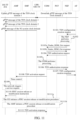
- a procedure in which a UDM performs control to perform a TSN time synchronization activation operation includes the following steps:
- Step S 801 An AF transmits a TSN configuration creation request to an NEF.
- a master clock of a TSN domain 1 may transmit an uplink gPTP message of the TSN clock domain 1 to a UPF/NW-TT through a UE (the UE is not the DS-TT/UE shown in FIG. 8 ), a master clock of a TSN field 2 may transmit a downlink gPTP message of the TSN clock domain 2 to the UPF/NW-TT through a terminal device (for example, another UE), and these messages are respectively used for performing TSN time synchronization operations of different TSN time domains.
- step S 801 for an example procedure of step S 801 , reference may be made to step 1 in chapter 6.8.3.1 “procedure for AF Requested the TSN Synchronization Activation” in 3GPP protocol TS23.700-20V0.3.0.
- the TSN configuration creation request in this embodiment of this application includes a Target ID, a TSN Activation Time, a TSN Domain ID, UL or DL TSN Synchronization, an Activation/Deactivation Indicator, an S-NSSAI, and a DNN. Because the embodiment shown in FIG. 8 is the TSN time synchronization activation operation, a value of the Activation/Deactivation Indicator is Activation.
- the Target ID refers to a particular UE, or a group of UEs.
- the Target ID is usually an SUPI, an IMSI, a GPSI, or another external application identifier.
- the Target ID refers to a group of UEs, the Target ID is usually an External Group ID.
- the TSN Activation Time is used for indicating whether to immediately perform the TSN time synchronization activation (or deactivation) operation, or perform the TSN time synchronization activation (or deactivation) operation after X seconds, or perform the TSN time synchronization activation (or deactivation) operation at a designated time point.
- Step S 802 The NEF performs processing.
- step S 802 for an example procedure of step S 802 , reference may be made to step 2 in chapter 6.8.3.1 “procedure for AF Requested the TSN Synchronization Activation” in 3GPP protocol TS23.700-20V0.3.0.
- Step S 803 a The NEF transmits a Nudm_SDM_Get request to a UDM.
- the Nudm_SDM_Get request may include the following parameters: Identifier Translation, a Target ID and, an AF Identifier.
- Step S 803 b The UDM transmits a Nudm_SDM_Get response to the NEF.
- the Nudm_SDM_Get response may include the following parameters: an SUPI and an optional MSISDN (Mobile Station International Integrated Service Digital Network Number).
- the Target ID may refer to a group of UEs.
- the Target ID refers to a group of UEs
- the Target ID is usually an External Group ID
- a reply of step S 803 b is an SUPI list and an optional MSISDN list.
- a similar operation needs to be performed on each SUPI (that is, each UE) in the list.
- the NEF transmits a TSN authorization request to the UDM.
- the TSN authorization request may include related parameters in the TSN configuration creation request, such as, the Target ID, the TSN Activation Time, the TSN Domain ID, the UL or DL TSN Synchronization, the Activation (indicating an activation operation), the S-NSSAI, and the DNN.
- Step S 805 The UDM performs processing.
- the UDM may determine whether to allow the NEF to request to add or modify subscription data of a UE; if yes, the UE subscription data may be added.
- the UE subscription data may include a TSN time domain identifier, first field information used for indicating uplink TSN synchronization or downlink TSN synchronization, second field information used for indicating an activation operation or a deactivation operation, network slice information, and a data network name. Then, the UDM may perform TSN activation and deactivation operations on the target UE based on information about this UE subscription data.
- Step S 806 The UDM returns a TSN authorization response to the NEF.
- Step S 807 The NEF returns a TSN configuration creation response to the AF.
- step S 804 to step S 807 reference may be made to step 3 to step 6 in chapter 6.8.3.1 “procedure for AF Requested the TSN Synchronization Activation” in 3GPP protocol TS23.700-20V0.3.0.
- Step S 808 The UDM transmits a TSN activation request to an AMF.
- the TSN activation request includes related parameters in the TSN authorization request, such as, the Target ID, the TSN Domain ID, the UL or DL TSN Synchronization, the Activation (indicating an activation operation), the S-NSSAI, and the DNN.
- the UDM When the TSN Activation Time included in the TSN authorization request indicates that the TSN time synchronization operation is performed immediately, the UDM immediately transmits the TSN activation request to an AMF that an SUPI of a UE (only a single UE when the Target ID in step S 801 refers to a single UE; or each UE when the Target ID in step S 801 refers to a group identifier) registers with the UDM, where this TSN activation request may include the TSN Domain ID, the UL or DL TSN Synchronization, the Activation, the S-NSSAI, the DNN, and the like.
- step S 808 , step S 806 , and step S 807 may not be in sequential order.
- the UDM transmits the TSN activation request after X seconds after receiving the TSN authorization request.
- the UDM transmits the TSN activation request at this particular time (when the particular time point is earlier than the current time point, the UDM immediately transmits the TSN activation request).
- One UE may register a plurality of AMFs (usually a maximum of two) with the UDM.
- the UDM may first transmit a message to the AMF whose RAT (Radio Access Technology) is 3GPP.
- the AMF may transmit, when determining that the PDU session is not established successfully, the TSN activation response indicating unsuccessful activation
- a message may be transmitted again to the corresponding AMF whose RAT is Non-3GPP.
- the UDM may simultaneously transmit the TSN activation request to the plurality of AMFs, and then when a TSN activation response fed back by each of the plurality of AMFs indicates unsuccessful activation or a PDU session registration message fed back by an SMF for the UE is not received in a set time, transmit the TSN activation request to the plurality of AMFs again.
- Step S 809 The AMF initiates a network triggered service request.
- the AMF may initiate a network triggered service request procedure, to establish signaling connection between the UE and the AMF.
- the step does not need to be performed.
- Step S 810 The AMF transmits a PDU session establishment instruction to the UE.
- the AMF may transmit an NAS message to the UE, to request the UE to establish a PDU session.
- the PDU session establishment instruction may include: the TSN Domain ID, the UL or DL TSN Synchronization, the Activation, the S-NSSAI, and the DNN.
- Step S 811 The UE initiates a PDU session establishment procedure.
- the PDU session establishment request in an N1 SM container initiated by the UE may include the following parameters: the TSN Domain ID, the UL or DL TSN Synchronization, the Activation, the S-NSSAI, and the DNN.
- the PDU session establishment request is transferred to the SMF through the AMF, and meanwhile the N1 message transmitted to the AMF includes the TSN Domain ID, the S-NSSAI, and the DNN.
- the SMF when registering with the UDM, the SMF provides the S-NSSAI, the DNN, and the TSN Domain ID, and therefore the UDM knows, by comparing the S-NSSAI, the DNN, and the TSN Domain ID, that the UE has successfully been triggered to perform the TSN activation procedure.
- Step S 812 The AMF feeds back a TSN activation response to the UDM.
- the step may be an optional step in some embodiments.
- the AMF may indicate, by feeding back the TSN activation response to the UDM, whether the TSN time synchronization is activated successfully.
- Step S 813 a When the TSN Domain ID is a TSN clock domain 1, the UPF/NW-TT transmits a gPTP message of the TSN clock domain 1 to the UE. Step S 813 b . When the TSN Domain ID is a TSN clock domain 2, the UPF/NW-TT transmits a gPTP message of the TSN clock domain 2 to the UE. Step S 813 c . When the TSN Domain ID indicates a 5G Time Domain, the UPF/NW-TT transmits a gPTP message of the 5G system clock domain to the UE.
- step S 813 a to step S 813 c reference may be made to 3GPP protocol TR23.700-020.
- the UPF/NW-TT forwards TSN synchronization related data in different directions according to the TSN Domain, to help the UE perform the TSN time synchronization processing.
- a procedure in which a UDM performs control to perform a TSN time synchronization deactivation operation includes the following steps:
- Step S 901 An AF transmits a TSN configuration creation request to an NEF.
- a master clock of a TSN domain 1 may transmit an uplink gPTP message of the TSN clock domain 1 to a UPF/NW-TT through a UE (the UE is not the DS-TT/UE shown in FIG. 9 );
- a master clock of a TSN field 2 may transmit a downlink gPTP message of the TSN clock domain 2 to the UPF/NW-TT through a terminal device (for example, another UE).
- the UPF/NW-TT transmits a gPTP message of the TSN clock domain 1 to the UE.
- the UPF/NW-TT transmits a gPTP message of the TSN clock domain 2 to the UE.
- the UPF/NW-TT transmits a gPTP message of the 5G system clock domain to the UE.
- step S 901 is similar to that of step S 801 in FIG. 8 , but the embodiment shown in FIG. 9 is the TSN time synchronization deactivation operation, and therefore a value of the Activation/Deactivation Indicator is Deactivation.
- Step S 902 The NEF performs processing.
- One embodiment of this step is similar to that of step S 802 in FIG. 8 .
- Step S 903 a The NEF transmits a Nudm_SDM_Get request to a UDM.
- a processing procedure of this step is similar to that of step S 803 a shown in FIG. 8 .
- Step S 903 b The UDM transmits a Nudm_SDM_Get response to the NEF.
- a processing procedure of this step is similar to that of step S 803 b shown in FIG. 8 .
- the Target ID may refer to a group of UEs.
- the Target ID refers to a group of UEs
- the Target ID is usually an External Group ID
- a reply of step S 903 b is an SUPI list and an optional MSISDN list.
- a similar operation needs to be performed on each SUPI (that is, each UE) in the list.
- the NEF transmits a TSN authorization request to the UDM.
- the TSN authorization request may include related parameters in the TSN configuration creation request, such as, the Target ID, the TSN Activation Time, the TSN Domain ID, the UL or DL TSN Synchronization, the Deactivation (indicating a deactivation operation), the S-NSSAI, and the DNN.
- Step S 905 The UDM performs processing.
- a processing procedure of this step is similar to that of step S 805 shown in FIG. 8 .
- Step S 906 The UDM returns a TSN authorization response to the NEF.
- Step S 907 The NEF returns a TSN configuration creation response to the AF.
- step S 904 to step S 907 reference may be made to step 3 to step 6 in chapter 6.8.3.1 “procedure for AF Requested the TSN Synchronization Activation” in 3GPP protocol TS23.700-20V0.3.0.
- Step S 908 The UDM transmits a TSN activation request to an AMF.
- the TSN activation request may include related parameters in the TSN authorization request, such as, the Target ID, the TSN Domain ID, the UL or DL TSN Synchronization, the Deactivation (indicating a deactivation operation), the S-NSSAI, and the DNN.
- related parameters in the TSN authorization request such as, the Target ID, the TSN Domain ID, the UL or DL TSN Synchronization, the Deactivation (indicating a deactivation operation), the S-NSSAI, and the DNN.
- the UDM When the TSN Activation Time included in the TSN authorization request received by the UDM indicates that the TSN time synchronization operation is performed immediately, the UDM immediately transmits the TSN activation request to an AMF that an SUPI of a UE (only a single UE when the Target ID in step S 901 refers to a single UE; or each UE when the Target ID in step S 901 refers to a group identifier) registers with the UDM, where this TSN activation request includes the TSN Domain ID, the UL or DL TSN Synchronization, the Deactivation, the S-NSSAI, the DNN, and the like.
- step S 908 , step S 906 , and step S 907 are not in sequential order.
- the UDM transmits the TSN activation request after X seconds after receiving the TSN authorization request.
- the UDM transmits the TSN activation request at this particular time (when the particular time point is earlier than the current time point, the UDM immediately transmits the TSN activation request).
- One UE may register a plurality of AMFs (usually a maximum of two) with the UDM.
- the UDM may first transmit the TSN activation request to the AMF whose RAT is 3GPP.
- a PDU session update context message transmitted by the SMF for the UE has not been received, or in step S 912 , the TSN activation response fed back by the AMF to the UDM indicates unsuccessful deactivation (the AMF may transmit, when determining that the PDU session is not released or modified successfully, the TSN activation response indicating unsuccessful deactivation), a TSN activation request may be transmitted again to the corresponding AMF whose RAT is Non-3GPP.
- the UDM may simultaneously transmit the TSN activation request to the plurality of AMFs, and then when a TSN activation response fed back by each of the plurality of AMFs indicates unsuccessful deactivation or a PDU session update context message fed back by an SMF for the UE is not received in a set time, transmit the TSN activation request to the plurality of AMFs again.
- Step S 909 The AMF initiates a network triggered service request.
- the AMF may initiate a network triggered service request procedure, to establish signaling connection between the UE and the AMF.
- the step does not need to be performed.
- steps S 910 and S 911 a are performed, but step S 911 b is not performed.
- step S 911 b is performed, but steps S 910 and S 911 a are not performed.
- Step S 910 The AMF transmits a PDU session release or modification instruction to the UE.
- the AMF may transmit an NAS message to the UE, to request the UE to release or modify a PDU session.
- the PDU session release or modification instruction includes: the TSN Domain ID, the UL or DL TSN Synchronization, the Deactivation, the S-NSSAI, and the DNN.
- Step S 911 a The UE initiates a PDU session release or modification procedure.
- a same PDU session may support different TSN Domains such as TSN Domains 1/2/3. Therefore, when a last TSN Domain is deleted, this PDU session needs to be deleted, and in one embodiment, the UE initiates the PDU session release procedure; and when only one of the TSN Domains is deleted, other TSN Domains exist, and in one embodiment, the UE initiates the PDU session modification procedure.
- the SMF releases functions of the UPF and the NW-TT related to the PDU session, that is, the UPF/NW-TT stops forwarding the TSN synchronization data of all the TSN Domains to the UE.
- a message of PDU Session Modification initiated by the UE includes a new parameter, that is, Deactivation of TSN Domain ID.
- the SMF instructs the UPF/the NW-TT not to forward the TSN synchronization data of this TSN Domain to this UE again.
- step S 911 a in the PDU session deleting or PDU session modification procedure, the SMF registers with the UDM, to instruct to delete the TSN Domain ID corresponding to the S-NSSAI and the DNN, and therefore the UDM knows, by comparing the S-NSSAI, the DNN, and the TSN Domain ID, that the UE has successfully been triggered to perform the TSN deactivation procedure.
- Step S 911 b The AMF initiates a PDU session release or modification procedure.
- steps S 910 and S 911 a shown in FIG. 9 do not need to be performed.
- steps S 910 and S 911 a shown in FIG. 9 are performed, while step S 911 b shown in the figure is not performed.
- a Nsmf_PDUSession_UpdateSMContext (PDU session-update session management context) message transmitted by the AMF to the SMF includes a new parameter, that is, deactivation of TSN Domain ID.
- the SMF instructs the UPF/the NW-TT not to forward the TSN synchronization data of this TSN Domain to this UE again.
- step S 911 b in the PDU session deleting or PDU session modification procedure, the SMF registers with the UDM, to instruct to delete the TSN Domain ID corresponding to the S-NSSAI and the DNN, and therefore the UDM knows, by comparing the S-NSSAI, the DNN, and the TSN Domain ID, that the UE has successfully been triggered to perform the TSN deactivation procedure.
- Step S 912 The AMF feeds back a TSN activation response to the UDM. This may be optional in some embodiments.
- the AMF may indicate, by feeding back the TSN activation response to the UDM, whether the TSN time synchronization is deactivated successfully.
- a procedure in which an AMF performs control to perform a TSN time synchronization activation operation includes the following steps:
- Step S 1001 An AF transmits a TSN configuration creation request to an NEF.
- a master clock of a TSN domain 1 may transmit an uplink gPTP message of the TSN clock domain 1 to a UPF/NW-TT through a UE (the UE is not the DS-TT/UE shown in FIG. 10 )
- a master clock of a TSN field 2 may transmit a downlink gPTP message of the TSN clock domain 2 to the UPF/NW-TT through a terminal device (for example, another UE), and these messages are respectively used for performing TSN time synchronization operations of different TSN time domains.
- step S 1001 is similar to that of step S 801 in FIG. 8 . Because the embodiment shown in FIG. 10 is the TSN time synchronization activation operation, a value of the Activation/Deactivation Indicator is Activation.
- Step S 1002 The NEF performs processing.
- One embodiment of this step is similar to that of step S 802 in FIG. 8 .
- Step S 1003 a The NEF transmits a Nudm_SDM_Get request to a UDM.
- One embodiment of this step is similar to that of step S 803 a in FIG. 8 .
- Step S 1003 b The UDM transmits a Nudm_SDM_Get response to the NEF.
- One embodiment of this step is similar to that of step S 803 b in FIG. 8 .
- the Target ID may refer to a group of UEs.
- the Target ID refers to a group of UEs
- the Target ID is usually an External Group ID
- a reply of step S 1003 b is an SUPI list and an optional MSISDN list.
- a similar operation needs to be performed on each SUPI (that is, each UE) in the list.
- Step S 1004 The NEF transmits a TSN authorization request to the UDM.
- the TSN authorization request includes related parameters in the TSN configuration creation request, such as, the Target ID, the TSN Activation Time, the TSN Domain ID, the UL or DL TSN Synchronization, the Activation (indicating an activation operation), the S-NSSAI, and the DNN.
- Step S 1005 The UDM performs processing.
- One embodiment of this step is similar to that of step S 805 in FIG. 8 .
- Step S 1006 The UDM returns a TSN authorization response to the NEF.
- Step S 1007 The NEF returns a TSN configuration creation response to the AF.
- step S 1004 to step S 1007 reference may be made to step 3 to step 6 in chapter 6.8.3.1 “procedure for AF Requested the TSN Synchronization Activation” in 3GPP protocol TS23.700-20V0.3.0.
- Step S 1008 The UDM transmits a TSN activation request to an AMF that an SUPI of a UE (only a single UE when the Target ID in step S 1001 refers to a single UE; or each UE when the Target ID in step S 1001 refers to a group identifier) registers with the UDM.
- the TSN activation request includes related parameters in the TSN authorization request, such as, the Target ID, the TSN Activation Time, the TSN Domain ID, the UL or DL TSN Synchronization, the Activation (indicating an activation operation), the S-NSSAI, and the DNN.
- Step S 1008 , step S 1006 , and step S 1007 are not in sequential order.
- One UE may register a plurality of AMFs (usually a maximum of two) with the UDM.
- the UDM may first transmit a message to the AMF whose RAT is 3GPP.
- a PDU session registration message transmitted by the SMF for the UE has not been received, or in step S 1012 , the TSN activation response fed back by the AMF to the UDM indicates unsuccessful activation (the AMF may transmit, when determining that the PDU session is not established successfully, the TSN activation response indicating unsuccessful activation), a message may be transmitted again to the corresponding AMF whose RAT is Non-3GPP.
- the UDM may simultaneously transmit the TSN activation request to the plurality of AMFs, and then when a TSN activation response fed back by each of the plurality of AMFs indicates unsuccessful activation or a PDU session registration message fed back by an SMF for the UE is not received in a set time, transmit the TSN activation request to the plurality of AMFs again.
- Step S 1009 The AMF initiates a network triggered service request.
- One embodiment of this step is similar to that of step S 809 in FIG. 8 .
- Step S 1010 The AMF transmits a PDU session establishment instruction to the UE.
- the PDU session establishment instruction may include: the TSN Domain ID, the UL or DL TSN Synchronization, the Activation, the S-NSSAI, and the DNN.
- the AMF when the TSN Activation Time in the TSN activation request received by the AMF indicates that the TSN time synchronization operation is performed immediately, the AMF immediately performs step S 1009 and step S 1010 .
- the TSN Activation Time indicates that the TSN time synchronization operation is performed after X seconds
- the AMF performs step S 1009 and step S 1010 after X seconds after receiving the TSN activation request.
- the TSN Activation Time indicates that the TSN time synchronization operation is performed at a particular time point
- the AMF performs step S 1009 and step S 1010 at this particular time (when the particular time point is earlier than the current time point, the AMF immediately performs step S 1009 and step S 1010 ).
- the AMF may initiate a network triggered service request procedure, to establish signaling connection between the UE and the AMF.
- step S 1009 does not need to be performed.
- the new AMF when the TSN Activation Time indicates that activation is performed after X seconds or indicates that the TSN time synchronization operation is performed at a particular time point, but when the activation time has not been reached, if the UE moves to a new AMF, the old AMF needs to transfer the trigger condition to the new AMF, for example, how much time is left before activation is performed, or what is the particular time point. In this way, the new AMF may continue to perform step S 1009 and subsequent steps.
- FIG. 14 is a flowchart of an old AMF transmitting context information to a new AMF in a procedure in which a UE registers the new AMF, which may include the following steps:
- Step S 1401 A UE initiates a registration request to an access network.
- Step S 1402 The access network selects an AMF.
- Step S 1403 The access network initiates a registration request to the new AMF.
- Step S 1404 The new AMF transmits a UE context transfer request (Namf_Communication_UEContextTransfer) to an old AMF.
- a UE context transfer request (Namf_Communication_UEContextTransfer)
- Step S 1405 The old AMF returns a UE context transfer response (Namf_Communication_UEContextTransfer response) to the new AMF.
- FIG. 14 further includes some additional steps in some embodiments.
- the old AMF may transmit a trigger condition to the new AMF by returning the UE context transfer response to the new AMF in step S 1405 .
- the trigger condition may include: a TSN Domain ID, UL or DL TSN Synchronization, Activation, an S-NSSAI, a DNN, and a TSN Activation Time.
- the time for transmission to the new AMF is not the time of initially receiving the TSN activation request, but a remaining time (that is, the time in the TSN activation request minus the elapsed time (a time that has elapsed after the TSN activation request is received by the old AMF)).
- FIG. 15 is a flowchart of an old AMF transmitting context information to a new AMF during network switching, which includes the following steps:
- Step S 1501 A source access network S-NG-RAN (that is, Source-NG-RAN) transmits, after determining to trigger switching through an N2 interface, a determined switching message to an S-AMF (Source-AMF).
- S-NG-RAN that is, Source-NG-RAN
- S-AMF Source-AMF
- Step S 1502 The S-AMF selects a target AMF.
- Step S 1503 The S-AMF transmits a create UE context request (Namf_Communication_CreateUEContext request) to a T-AMF (Target-AMF).
- a create UE context request (Namf_Communication_CreateUEContext request)
- T-AMF Target-AMF
- Step S 1504 The T-AMF transmits an update session management context request (Namf_PDUSession_UpdateSMContext Request) to the SMF.
- Namf_PDUSession_UpdateSMContext Request an update session management context request
- FIG. 15 further includes other steps in some embodiments.
- the old AMF may transmit a trigger condition to the new AMF by transmitting the create UE context request to the new AMF in step S 1503 .
- the trigger condition includes: a TSN Domain ID, UL or DL TSN Synchronization, Activation, an S-NSSAI, a DNN, and a TSN Activation Time.
- the time for transmission to the new AMF is not the time of initially receiving the TSN activation request, but a remaining time (that is, the time in the TSN activation request minus the elapsed time (a time that has elapsed after the TSN activation request is received by the old AMF)).
- Step S 1011 includes the UE initiates a PDU session establishment procedure.
- One embodiment of this step is similar to that of step S 811 in FIG. 8 .
- Step S 1012 The AMF feeds back a TSN activation response to the UDM. This may be optional in some embodiments.
- the AMF may indicate, by feeding back the TSN activation response to the UDM, whether the TSN time synchronization is activated successfully.
- Step S 1013 a When the TSN Domain ID is a TSN clock domain 1, the UPF/NW-TT transmits a gPTP message of the TSN clock domain 1 to the UE. Step S 1013 b . When the TSN Domain ID is a TSN clock domain 2, the UPF/NW-TT transmits a gPTP message of the TSN clock domain 2 to the UE. Step S 1013 c . When the TSN Domain ID indicates a 5G Time Domain, the UPF/NW-TT transmits a gPTP message of the 5G system clock domain to the UE.
- step S 1013 a to step S 1013 c reference may be made to 3GPP protocol TR23.700-020.
- the UPF/NW-TT forwards TSN synchronization related data in different directions according to the TSN Domain, to help the UE perform the TSN time synchronization processing.
- a procedure in which an AMF performs control to perform a TSN time synchronization deactivation operation includes the following steps:
- Step S 1101 An AF transmits a TSN configuration creation request to an NEF.
- a master clock of a TSN domain 1 may transmit an uplink gPTP message of the TSN clock domain 1 to a UPF/NW-TT through a UE (the UE is not the DS-TT/UE shown in FIG. 11 );
- a master clock of a TSN field 2 may transmit a downlink gPTP message of the TSN clock domain 2 to the UPF/NW-TT through a terminal device (for example, another UE).
- the UPF/NW-TT transmits a gPTP message of the TSN clock domain 1 to the UE.
- the UPF/NW-TT transmits a gPTP message of the TSN clock domain 2 to the UE.
- the UPF/NW-TT transmits a gPTP message of the 5G system clock domain to the UE.
- step S 1101 is similar to that of step S 801 in FIG. 8 , but the embodiment shown in FIG. 11 is the TSN time synchronization deactivation operation, and therefore a value of the Activation/Deactivation Indicator is Deactivation.
- Step S 1102 The NEF performs processing.
- One embodiment of this step is similar to that of step S 802 in FIG. 8 .
- Step S 1103 a The NEF transmits a Nudm_SDM_Get request to a UDM.
- a processing procedure of this step is similar to that of step S 803 a shown in FIG. 8 .
- Step S 1103 b The UDM transmits a Nudm_SDM_Get response to the NEF.
- a processing procedure of this step is similar to that of step S 803 b shown in FIG. 8 .
- the Target ID may refer to a group of UEs.
- the Target ID refers to a group of UEs
- the Target ID is usually an External Group ID
- a reply of step S 1103 b is an SUPI list and an optional MSISDN list.
- a similar operation needs to be performed on each SUPI (that is, each UE) in the list.
- Step S 1104 The NEF transmits a TSN authorization request to the UDM.
- the TSN authorization request may include related parameters in the TSN configuration creation request, such as, the Target ID, the TSN Activation Time, the TSN Domain ID, the UL or DL TSN Synchronization, the Deactivation (indicating a deactivation operation), the S-NSSAI, and the DNN.
- Step S 1105 The UDM performs processing.
- a processing procedure of this step is similar to that of step S 805 shown in FIG. 8 .
- Step S 1106 The UDM returns a TSN authorization response to the NEF.
- Step S 1107 The NEF returns a TSN configuration creation response to the AF.
- step S 1104 to step S 1107 reference may be made to step 3 to step 6 in chapter 6.8.3.1 “procedure for AF Requested the TSN Synchronization Activation” in 3GPP protocol TS23.700-20V0.3.0.
- Step S 1108 The UDM transmits a TSN activation request to an AMF that an SUPI of a UE (only a single UE when the Target ID in step S 1001 refers to a single UE; or each UE when the Target ID in step S 1001 refers to a group identifier) registers with the UDM.
- the TSN activation request includes related parameters in the TSN authorization request, such as, the Target ID, the TSN Activation Time, the TSN Domain ID, the UL or DL TSN Synchronization, the Deactivation (indicating a deactivation operation), the S-NSSAI, and the DNN.
- Step S 1008 , step S 1006 , and step S 1007 are not in sequential order.
- One UE may register a plurality of AMFs (usually a maximum of two) with the UDM.
- the UDM may first transmit the TSN activation request to the AMF whose RAT is 3GPP.
- a PDU session update context message transmitted by the SMF for the UE has not been received, or in step S 1112 , the TSN activation response fed back by the AMF to the UDM indicates unsuccessful deactivation (the AMF may transmit, when determining that the PDU session is not released or modified successfully, the TSN activation response indicating unsuccessful deactivation), a TSN activation request may be transmitted again to the corresponding AMF whose RAT is Non-3GPP.
- the UDM may simultaneously transmit the TSN activation request to the plurality of AMFs, and then when a TSN activation response fed back by each of the plurality of AMFs indicates unsuccessful deactivation or a PDU session update context message fed back by an SMF for the UE is not received in a set time, transmit the TSN activation request to the plurality of AMFs again.
- Step S 1109 The AMF initiates a network triggered service request.
- Step S 1110 The AMF transmits a PDU session release or modification instruction to the UE.
- the PDU session release or modification instruction may include: the TSN Domain ID, the UL or DL TSN Synchronization, the Deactivation, the S-NSSAI, and the DNN.
- the AMF when the TSN Activation Time in the TSN activation request received by the AMF indicates that the TSN time synchronization operation is performed immediately, the AMF immediately performs step S 1009 and step S 1010 .
- the TSN Activation Time indicates that the TSN time synchronization operation is performed after X seconds
- the AMF performs step S 1009 and step S 1010 after X seconds after receiving the TSN activation request.
- the TSN Activation Time indicates that the TSN time synchronization operation is performed at a particular time point
- the AMF performs step S 1009 and step S 1010 at this particular time (when the particular time point is earlier than the current time point, the AMF immediately performs step S 1009 and step S 1010 ).
- the AMF may initiate a network triggered service request procedure, to establish signaling connection between the UE and the AMF.
- step S 1009 does not need to be performed.
- the new AMF may continue to perform step S 1109 and subsequent steps.
- FIG. 14 and FIG. 15 for the registration procedure shown in FIG.
- the trigger condition in the UE context transfer response returned by the old AMF to the new AMF in step S 1405 may include: a TSN Domain ID, UL or DL TSN Synchronization, Deactivation, an S-NSSAI, a DNN, and a TSN Activation Time.
- the trigger condition in the create UE context request transmitted by the old AMF to the new AMF in step S 1503 may include: a TSN Domain ID, UL or DL TSN Synchronization, Deactivation, an S-NSSAI, a DNN, and a TSN Activation Time.
- Step S 1111 a The UE initiates a PDU session release or modification procedure.
- a processing procedure of this step is similar to that of step S 911 a shown in FIG. 9 .
- Step S 1111 b The AMF initiates a PDU session release or modification procedure.
- a processing procedure of this step is similar to that of step S 911 b shown in FIG. 9 .
- steps S 1110 and S 1111 a shown in FIG. 11 do not need to be performed.
- steps S 1110 and S 1111 a are performed, but step S 1111 b is not performed.
- a Nsmf_PDUSession_UpdateSMContext (PDU session-update session management context) message transmitted by the AMF to the SMF includes a new parameter, that is, deactivation of TSN Domain ID.
- the SMF instructs the UPF/the NW-TT not to forward the TSN synchronization data of this TSN Domain to this UE again.
- Step S 1112 The AMF feeds back a TSN activation response to the UDM. This may be optional in some embodiments.
- the AMF may indicate, by feeding back the TSN activation response to the UDM, whether the TSN time synchronization is deactivated successfully.
- a procedure in which a UE performs control to perform a TSN time synchronization activation operation includes the following steps:
- Step S 1201 An AF transmits a TSN configuration creation request to an NEF.
- a master clock of a TSN domain 1 may transmit an uplink gPTP message of the TSN clock domain 1 to a UPF/NW-TT through a UE (the UE is not the DS-TT/UE shown in FIG. 12 )
- a master clock of a TSN field 2 may transmit a downlink gPTP message of the TSN clock domain 2 to the UPF/NW-TT through a terminal device (for example, another UE), and these messages are respectively used for performing TSN time synchronization operations of different TSN time domains.
- step S 1201 is similar to that of step S 801 in FIG. 8 . Because the embodiment shown in FIG. 12 is the TSN time synchronization activation operation, a value of the Activation/Deactivation Indicator is Activation.
- Step S 1202 The NEF performs processing.
- One embodiment of this step is similar to that of step S 802 in FIG. 8 .
- Step S 1203 a The NEF transmits a Nudm_SDM_Get request to a UDM.
- One embodiment of this step is similar to that of step S 803 a in FIG. 8 .
- Step S 1203 b The UDM transmits a Nudm_SDM_Get response to the NEF.
- One embodiment of this step is similar to that of step S 803 b in FIG. 8 .
- the Target ID may refer to a group of UEs.
- the Target ID refers to a group of UEs
- the Target ID is usually an External Group ID
- a reply of step S 1203 b is an SUPI list and an optional MSISDN list.
- a similar operation needs to be performed on each SUPI (that is, each UE) in the list.
- the NEF transmits a TSN authorization request to the UDM.
- the TSN authorization request may include related parameters in the TSN configuration creation request, such as, the Target ID, the TSN Activation Time, the TSN Domain ID, the UL or DL TSN Synchronization, the Activation (indicating an activation operation), the S-NSSAI, and the DNN.
- Step S 1205 The UDM performs processing.
- One embodiment of this step is similar to that of step S 805 in FIG. 8 .
- Step S 1206 The UDM returns a TSN authorization response to the NEF.
- Step S 1207 The NEF returns a TSN configuration creation response to the AF.
- step S 1204 to step S 1207 reference may be made to step 3 to step 6 in chapter 6.8.3.1 “procedure for AF Requested the TSN Synchronization Activation” in 3GPP protocol TS23.700-20V0.3.0.
- Step S 1208 The UDM transmits a TSN activation request to an AMF that an SUPI of a UE (only a single UE when the Target ID in step S 1201 refers to a single UE; or each UE when the Target ID in step S 1201 refers to a group identifier) registers with the UDM.
- the TSN activation request includes related parameters in the TSN authorization request, such as, the Target ID, the TSN Activation Time, the TSN Domain ID, the UL or DL TSN Synchronization, the Activation (indicating an activation operation), the S-NSSAI, and the DNN.
- Step S 1208 , step S 1206 , and step S 1207 are not in sequential order.
- One UE may register a plurality of AMFs (usually a maximum of two) with the UDM.
- the UDM may first transmit a message to the AMF whose RAT is 3GPP.
- the TSN activation response fed back by the AMF to the UDM indicates unsuccessful activation (the AMF may transmit, when determining that the PDU session is not established successfully, the TSN activation response indicating unsuccessful activation), the UDM may transmit a message again to the corresponding AMF whose RAT is Non-3GPP.
- the UDM may simultaneously transmit the TSN activation request to the plurality of AMFs, and then when a TSN activation response fed back by each of the plurality of AMFs indicates unsuccessful activation or a PDU session registration message fed back by an SMF for the UE is not received in a set time, transmit the TSN activation request to the plurality of AMFs again.
- Step S 1209 The AMF initiates a network triggered service request.
- the AMF may initiate a network triggered service request procedure, to establish signaling connection between the UE and the AMF.
- step S 1209 does not need to be performed.
- Step S 1210 The AMF transmits a PDU session establishment instruction to the UE.
- the PDU session establishment instruction may include: the TSN Domain ID, the TSN Activation Time, the UL or DL TSN Synchronization, the Activation, the S-NSSAI, and the DNN.
- Step S 1211 The UE initiates a service request procedure.
- step S 1211 when the TSN Activation Time in the PDU session establishment instruction received by the UE indicates that the TSN time synchronization operation is performed immediately. In one embodiment, because the UE is still in the connected state, step S 1211 may be skipped, and subsequent steps are directly performed.
- the UE determines, after X seconds after receiving the PDU session establishment instruction, whether the UE is in the CM-IDLE state, and if yes, step S 1211 is performed, to establish signaling connection to the AMF, and then subsequent steps are performed; and if the UE is still in the connected state, step S 1211 is skipped, and subsequent steps are directly performed.
- the UE determines, at the particular time point, whether the UE is in the CM-IDLE state, and if yes, step S 1211 is performed, to establish signaling connection to the AMF, and then subsequent steps are performed; and if the UE is still in the connected state, step S 1211 is skipped, and subsequent steps are directly performed.
- the TSN Activation Time indicates that the TSN time synchronization operation is performed after X seconds or indicates that the TSN time synchronization operation is performed at a particular time point, but when the activation time has not been reached, if the UE moves to a new AMF, the UE may continue to perform subsequent steps, and this method is not affected.
- this time synchronization is not the TSN time synchronization (synchronization precision is at the microsecond level, and a synchronization error is less than 1 ms), but the UE obtains a current local time from the network through NAS signaling, and the synchronization precision is usually in a range of 50 ms to 1 second).
- Step S 1212 The UE initiates a PDU session establishment procedure.
- One embodiment of this step is similar to that of step S 811 in FIG. 8 .
- Step S 1213 The AMF feeds back a TSN activation response to the UDM. This may be optional in some embodiments.
- the AMF may indicate, by feeding back the TSN activation response to the UDM, whether the TSN time synchronization is activated successfully.
- Step S 1214 a When the TSN Domain ID is a TSN clock domain 1, the UPF/NW-TT transmits a gPTP message of the TSN clock domain 1 to the UE. Step S 1214 b . When the TSN Domain ID is a TSN clock domain 2, the UPF/NW-TT transmits a gPTP message of the TSN clock domain 2 to the UE. Step S 1214 c . When the TSN Domain ID indicates a 5G Time Domain, the UPF/NW-TT transmits a gPTP message of the 5G system clock domain to the UE.
- step S 1214 a to step S 1214 c reference may be made to 3GPP protocol TR23.700-020.
- the UPF/NW-TT forwards TSN synchronization related data in different directions according to the TSN Domain, to help the UE perform the TSN time synchronization processing.
- a procedure in which a UE performs control to perform a TSN time synchronization deactivation operation includes the following steps:
- Step S 1301 An AF transmits a TSN configuration creation request to an NEF.
- a master clock of a TSN domain 1 may transmit an uplink gPTP message of the TSN clock domain 1 to a UPF/NW-TT through a UE (the UE is not the DS-TT/UE shown in FIG. 13 );
- a master clock of a TSN field 2 may transmit a downlink gPTP message of the TSN clock domain 2 to the UPF/NW-TT through a terminal device (for example, another UE).
- the UPF/NW-TT transmits a gPTP message of the TSN clock domain 1 to the UE.
- the UPF/NW-TT transmits a gPTP message of the TSN clock domain 2 to the UE.
- the UPF/NW-TT transmits a gPTP message of the 5G system clock domain to the UE.
- step S 1301 is similar to that of step S 801 in FIG. 8 , but the embodiment shown in FIG. 13 is the TSN time synchronization deactivation operation, and therefore a value of the Activation/Deactivation Indicator is Deactivation.
- Step S 1302 The NEF performs processing.
- One embodiment of this step is similar to that of step S 802 in FIG. 8 .
- Step S 1303 a The NEF transmits a Nudm_SDM_Get request to a UDM.
- a processing procedure of this step is similar to that of step S 803 a shown in FIG. 8 .
- Step S 1303 b The UDM transmits a Nudm_SDM_Get response to the NEF.
- a processing procedure of this step is similar to that of step S 803 b shown in FIG. 8 .
- the Target ID may refer to a group of UEs.
- the Target ID refers to a group of UEs
- the Target ID is usually an External Group ID
- a reply of step S 1303 b is an SUPI list and an optional MSISDN list.
- a similar operation needs to be performed on each SUPI (that is, each UE) in the list.
- Step S 1304 The NEF transmits a TSN authorization request to the UDM.
- the TSN authorization request may include related parameters in the TSN configuration creation request, such as, the Target ID, the TSN Activation Time, the TSN Domain ID, the UL or DL TSN Synchronization, the Deactivation (indicating a deactivation operation), the S-NSSAI, and the DNN.
- Step S 1305 The UDM performs processing.
- One embodiment of this step is similar to that of step S 805 in FIG. 8 .
- Step S 1306 The UDM returns a TSN authorization response to the NEF.
- Step S 1307 The NEF returns a TSN configuration creation response to the AF.
- step S 1304 to step S 1307 reference may be made to step 3 to step 6 in chapter 6.8.3.1 “procedure for AF Requested the TSN Synchronization Activation” in 3GPP protocol TS23.700-20V0.3.0.
- Step S 1308 The UDM transmits a TSN activation request to an AMF that an SUPI of a UE (only a single UE when the Target ID in step S 1001 refers to a single UE; or each UE when the Target ID in step S 1001 refers to a group identifier) registers with the UDM.
- the TSN activation request includes related parameters in the TSN authorization request, such as, the Target ID, the TSN Activation Time, the TSN Domain ID, the UL or DL TSN Synchronization, the Deactivation (indicating a deactivation operation), the S-NSSAI, and the DNN.
- Step S 1008 , step S 1006 , and step S 1007 are not in sequential order.
- One UE may register a plurality of AMFs (usually a maximum of two) with the UDM.
- the UDM may first transmit the TSN activation request to the AMF whose RAT is 3GPP.
- a PDU session update context message transmitted by the SMF for the UE has not been received, or in step S 1312 , the TSN activation response fed back by the AMF to the UDM indicates unsuccessful deactivation (the AMF may transmit, when determining that the PDU session is not released or modified successfully, the TSN activation response indicating unsuccessful deactivation), the UDM may transmit a TSN activation request again to the corresponding AMF whose RAT is Non-3GPP.
- the UDM may simultaneously transmit the TSN activation request to the plurality of AMFs, and then when a TSN activation response fed back by each of the plurality of AMFs indicates unsuccessful deactivation or a PDU session update context message fed back by an SMF for the UE is not received in a set time, transmit the TSN activation request to the plurality of AMFs again.
- Step S 1309 The AMF initiates a network triggered service request.
- a processing procedure of this step is similar to that of step S 1209 shown in FIG. 12 .
- Step S 1310 The AMF transmits a PDU session release or modification instruction to the UE.
- the PDU session release or modification instruction may include: the TSN Domain ID, the TSN Activation Time, the UL or DL TSN Synchronization, the Deactivation, the S-NSSAI, and the DNN.
- Step S 1311 The UE initiates a service request procedure.
- step S 1311 when the TSN Activation Time in the PDU session release or modification instruction received by the UE indicates that the TSN time synchronization operation is performed immediately. In one embodiment, because the UE is still in the connected state, step S 1311 may be skipped, and subsequent steps are directly performed.
- the UE determines, after X seconds after receiving the PDU session release or modification instruction, whether the UE is in the CM-IDLE state, and if yes, step S 1311 is performed, to establish signaling connection to the AMF, and then subsequent steps are performed; and if the UE is still in the connected state, step S 1311 is skipped, and subsequent steps are directly performed.
- the UE determines, at the particular time point, whether the UE is in the CM-IDLE state, and if yes, step S 1211 is performed, to establish signaling connection to the AMF, and then subsequent steps are performed; and if the UE is still in the connected state, step S 1311 is skipped, and subsequent steps are directly performed.
- the TSN Activation Time indicates that the TSN time synchronization operation is performed after X seconds or indicates that the TSN time synchronization operation is performed at a particular time point, but when the deactivation time has not been reached, if the UE moves to a new AMF, the UE may continue to perform subsequent steps, and this method is not affected.
- this time synchronization is not the TSN time synchronization, but synchronization in which the UE obtains time from the network through NAS signaling, and the synchronization precision is in a range of 1 second).
- Step S 1312 The UE initiates a PDU session release or modification procedure.
- a processing procedure of this step is similar to that of step S 911 a shown in FIG. 9 .
- Step S 1313 The AMF feeds back a TSN activation response to the UDM. This may be optional in some embodiments.
- the AMF may indicate, by feeding back the TSN activation response to the UDM, whether the TSN time synchronization is deactivated successfully.
- the solutions in which the UDM, the AMF, and the UE control the occasion on which the UE performs the TSN time synchronization operation are respectively described.
- the NEF may alternatively control the occasion on which the UE performs the TSN time synchronization operation.
- a procedure in which an NEF performs control to perform a TSN time synchronization activation operation includes the following steps:
- Step S 1601 An AF transmits a TSN configuration creation request to an NEF.
- a master clock of a TSN domain 1 may transmit an uplink gPTP message of the TSN clock domain 1 to a UPF/NW-TT through a UE (the UE is not the DS-TT/UE shown in FIG. 16 )
- a master clock of a TSN field 2 may transmit a downlink gPTP message of the TSN clock domain 2 to the UPF/NW-TT through a terminal device (for example, another UE), and these messages are respectively used for performing TSN time synchronization operations of different TSN time domains.
- step S 1601 is similar to that of step S 801 in FIG. 8 . Because the embodiment shown in FIG. 16 is the TSN time synchronization activation operation, a value of the Activation/Deactivation Indicator is Activation.
- Step S 1602 The NEF performs processing.
- One embodiment of this step is similar to that of step S 802 in FIG. 8 .
- Step S 1603 a The NEF transmits a Nudm_SDM_Get request to a UDM.
- One embodiment of this step is similar to that of step S 803 a in FIG. 8 .
- Step S 1603 b The UDM transmits a Nudm_SDM_Get response to the NEF.
- One embodiment of this step is similar to that of step S 803 b in FIG. 8 .
- the Target ID may refer to a group of UEs.
- the Target ID refers to a group of UEs
- the Target ID is usually an External Group ID
- a reply of step S 1603 b is an SUPI list and an optional MSISDN list.
- a similar operation needs to be performed on each SUPI (that is, each UE) in the list.
- Step S 1604 The NEF transmits a TSN authorization request to the UDM.
- the NEF when the TSN Activation Time included in the TSN configuration creation request indicates that the TSN time synchronization operation is performed immediately, the NEF immediately transmits the TSN authorization request to the UDM; When the TSN Activation Time indicates that the TSN time synchronization operation is performed after X seconds, the NEF transmits, after X seconds after receiving the TSN configuration creation request, the TSN authorization request to the UDM; and when the TSN Activation Time indicates that the TSN time synchronization operation is performed at a designated time point, the NEF transmits the TSN authorization request to the UDM at the designated time point (when the particular time point is earlier than the current time point, the NEF immediately transmits the TSN authorization request).
- the TSN authorization request may include related parameters in the TSN configuration creation request, such as, the Target ID, the TSN Domain ID, the UL or DL TSN Synchronization, the Activation (indicating an activation operation), the S-NSSAI, and the DNN.
- Step S 1605 The UDM performs processing.
- One embodiment of this step is similar to that of step S 805 in FIG. 8 .
- Step S 1606 The UDM returns a TSN authorization response to the NEF.
- Step S 1607 The NEF returns a TSN configuration creation response to the AF.
- step S 1604 to step S 1607 reference may be made to step 3 to step 6 in chapter 6.8.3.1 “procedure for AF Requested the TSN Synchronization Activation” in 3GPP protocol TS23.700-20V0.3.0.
- Step S 1608 The UDM transmits a TSN activation request to an AMF that an SUPI of a UE (only a single UE when the Target ID in step S 1601 refers to a single UE; or each UE when the Target ID in step S 1601 refers to a group identifier) registers with the UDM.
- the TSN activation request includes related parameters in the TSN authorization request, such as, the Target ID, the TSN Domain ID, the UL or DL TSN Synchronization, the Activation (indicating an activation operation), the S-NSSAI, and the DNN.
- Step S 1608 , step S 1606 , and step S 1607 are not in sequential order.
- Step S 1609 The AMF initiates a network triggered service request.
- the AMF may initiate a network triggered service request procedure, to establish signaling connection between the UE and the AMF.
- the step does not need to be performed.
- Step S 1610 The AMF transmits a PDU session establishment instruction to the UE.
- the AMF may transmit an NAS message to the UE, to request the UE to establish a PDU session.
- the PDU session establishment instruction may include: the TSN Domain ID, the UL or DL TSN Synchronization, the Activation, the S-NSSAI, and the DNN.
- Step S 1611 The UE initiates a PDU session establishment procedure.
- One embodiment of this step is similar to that of step S 811 in FIG. 8 .
- Step S 1612 The AMF feeds back a TSN activation response to the UDM. This may be optional in some embodiments.
- the AMF may indicate, by feeding back the TSN activation response to the UDM, whether the TSN time synchronization is activated successfully.
- Step S 1613 a When the TSN Domain ID is a TSN clock domain 1, the UPF/NW-TT transmits a gPTP message of the TSN clock domain 1 to the UE. Step S 1613 b . When the TSN Domain ID is a TSN clock domain 2, the UPF/NW-TT transmits a gPTP message of the TSN clock domain 2 to the UE. Step S 1613 c . When the TSN Domain ID indicates a 5G Time Domain, the UPF/NW-TT transmits a gPTP message of the 5G system clock domain to the UE.
- step S 1613 a to step S 1613 c reference may be made to 3GPP protocol TR23.700-020.
- the UPF/NW-TT forwards TSN synchronization related data in different directions according to the TSN Domain, to help the UE perform the TSN time synchronization processing.
- a procedure in which an NEF performs control to perform a TSN time synchronization deactivation operation includes the following steps:
- Step S 1701 An AF transmits a TSN configuration creation request to an NEF.
- a master clock of a TSN domain 1 may transmit an uplink gPTP message of the TSN clock domain 1 to a UPF/NW-TT through a UE (the UE is not the DS-TT/UE shown in FIG. 17 );
- a master clock of a TSN field 2 may transmit a downlink gPTP message of the TSN clock domain 2 to the UPF/NW-TT through a terminal device (for example, another UE).
- the UPF/NW-TT transmits a gPTP message of the TSN clock domain 1 to the UE.
- the UPF/NW-TT transmits a gPTP message of the TSN clock domain 2 to the UE.
- the UPF/NW-TT transmits a gPTP message of the 5G system clock domain to the UE.
- step S 1701 is similar to that of step S 801 in FIG. 8 , but the embodiment shown in FIG. 17 is the TSN time synchronization deactivation operation, and therefore a value of the Activation/Deactivation Indicator is Deactivation.
- Step S 1702 The NEF performs processing.
- One embodiment of this step is similar to that of step S 802 in FIG. 8 .
- Step S 1703 a The NEF transmits a Nudm_SDM_Get request to a UDM.
- a processing procedure of this step is similar to that of step S 803 a shown in FIG. 8 .
- Step S 1703 b The UDM transmits a Nudm_SDM_Get response to the NEF.
- a processing procedure of this step is similar to that of step S 803 b shown in FIG. 8 .
- the Target ID may refer to a group of UEs.
- the Target ID refers to a group of UEs
- the Target ID is usually an External Group ID
- a reply of step S 1703 b is an SUPI list and an optional MSISDN list.
- a similar operation needs to be performed on each SUPI (that is, each UE) in the list.
- Step S 1704 The NEF transmits a TSN authorization request to the UDM.
- the NEF when the TSN Activation Time included in the TSN configuration creation request indicates that the TSN time synchronization operation is performed immediately, the NEF immediately transmits the TSN authorization request to the UDM; When the TSN Activation Time indicates that the TSN time synchronization operation is performed after X seconds, the NEF transmits, after X seconds after receiving the TSN configuration creation request, the TSN authorization request to the UDM; and when the TSN Activation Time indicates that the TSN time synchronization operation is performed at a designated time point, the NEF transmits the TSN authorization request to the UDM at the designated time point (when the particular time point is earlier than the current time point, the NEF immediately transmits the TSN authorization request).
- the TSN authorization request may include related parameters in the TSN configuration creation request, such as, the Target ID, the TSN Domain ID, the UL or DL TSN Synchronization, the Deactivation (indicating a deactivation operation), the S-NSSAI, and the DNN.
- Step S 1705 The UDM performs processing.
- a processing procedure of this step is similar to that of step S 805 shown in FIG. 8 .
- Step S 1706 The UDM returns a TSN authorization response to the NEF.
- Step S 1707 The NEF returns a TSN configuration creation response to the AF.
- step S 1704 to step S 1707 reference may be made to step 3 to step 6 in chapter 6.8.3.1 “procedure for AF Requested the TSN Synchronization Activation” in 3GPP protocol TS23.700-20V0.3.0.
- Step S 1708 The UDM transmits a TSN activation request to an AMF that an SUPI of a UE (only a single UE when the Target ID in step S 1701 refers to a single UE; or each UE when the Target ID in step S 1701 refers to a group identifier) registers with the UDM.
- the TSN activation request includes related parameters in the TSN authorization request, such as, the Target ID, the TSN Domain ID, the UL or DL TSN Synchronization, the Deactivation (indicating a deactivation operation), the S-NSSAI, and the DNN.
- Step S 1708 , step S 1706 , and step S 1707 are not in sequential order.
- Step S 1709 The AMF initiates a network triggered service request.
- the AMF may initiate a network triggered service request procedure, to establish signaling connection between the UE and the AMF.
- the step does not need to be performed.
- Step S 1710 The AMF transmits a PDU session release or modification instruction to the UE.
- the AMF may transmit an NAS message to the UE, to request the UE to release or modify a PDU session.
- the PDU session release or modification instruction may include: the TSN Domain ID, the UL or DL TSN Synchronization, the Deactivation, the S-NSSAI, and the DNN.
- Step S 1711 a The UE initiates a PDU session release or modification procedure.
- a processing procedure of this step is similar to that of step S 911 a shown in FIG. 9 .
- Step S 1711 b The AMF initiates a PDU session release or modification procedure.
- a processing procedure of this step is similar to that of step S 911 b shown in FIG. 9 .
- steps S 1710 and S 1711 a shown in FIG. 17 do not need to be performed.
- steps S 1710 and S 1711 a are performed, but step S 1711 b is not performed.
- Step S 1712 The AMF feeds back a TSN activation response to the UDM. This may be optional in some embodiments.
- the AMF may indicate, by feeding back the TSN activation response to the UDM, whether the TSN time synchronization is deactivated successfully.
- a procedure in which an NEF performs control to perform a TSN time synchronization activation operation includes the following steps:
- Step S 1801 An AF transmits a TSN configuration creation request to an NEF.
- a master clock of a TSN domain 1 may transmit an uplink gPTP message of the TSN clock domain 1 to a UPF/NW-TT through a UE (the UE is not the DS-TT/UE shown in FIG. 18 ), a master clock of a TSN field 2 may transmit a downlink gPTP message of the TSN clock domain 2 to the UPF/NW-TT through a terminal device (for example, another UE), and these messages are respectively used for performing TSN time synchronization operations of different TSN time domains.
- step S 1801 is similar to that of step S 801 in FIG. 8 . Because the embodiment shown in FIG. 18 is the TSN time synchronization activation operation, a value of the Activation/Deactivation Indicator is Activation.
- Step S 1802 The NEF performs processing.
- One embodiment of this step is similar to that of step S 802 in FIG. 8 .
- Step S 1803 a The NEF transmits a Nudm_SDM_Get request to a UDM.
- One embodiment of this step is similar to that of step S 803 a in FIG. 8 .
- Step S 1803 b The UDM transmits a Nudm_SDM_Get response to the NEF.
- One embodiment of this step is similar to that of step S 803 b in FIG. 8 .
- the Target ID may refer to a group of UEs.
- the Target ID refers to a group of UEs
- the Target ID is usually an External Group ID
- a reply of step S 1803 b is an SUPI list and an optional MSISDN list.
- a similar operation needs to be performed on each SUPI (that is, each UE) in the list.
- Step S 1804 The NEF transmits a TSN authorization request to the UDM.
- the TSN authorization request may include related parameters in the TSN configuration creation request, such as, the Target ID, the TSN Domain ID, the UL or DL TSN Synchronization, the Activation (indicating an activation operation), the S-NSSAI, and the DNN.
- the TSN authorization request may alternatively include the TSN Activation Time.
- Step S 1805 The UDM performs processing.
- One embodiment of this step is similar to that of step S 805 in FIG. 8 .
- Step S 1806 The UDM returns a TSN authorization response to the NEF.
- the TSN authorization response includes information about an AMF that the UE registers with the UDM.
- Step S 1807 The NEF returns a TSN configuration creation response to the AF.
- step S 1804 to step S 1807 reference may be made to step 3 to step 6 in chapter 6.8.3.1 “procedure for AF Requested the TSN Synchronization Activation” in 3GPP protocol TS23.700-20V0.3.0.
- Step S 1808 The NEF transmits a TSN activation request to the AMF.
- the NEF when the NEF transmits a TSN activation request to the AMF, when the TSN Activation Time included in the TSN configuration creation request received by the NEF indicates that the TSN time synchronization operation is performed immediately, the NEF immediately transmits the TSN activation request to an AMF that an SUPI of a UE (only a single UE when the Target ID in step S 1801 refers to a single UE; or each UE when the Target ID in step S 1801 refers to a group identifier) registers with the UDM, where this TSN activation request includes the TSN Domain ID, the UL or DL TSN Synchronization, the Activation, the S-NSSAI, the DNN, and the like.
- an SUPI of a UE only a single UE when the Target ID in step S 1801 refers to a single UE; or each UE when the Target ID in step S 1801 refers to a group identifier
- this TSN activation request includes the TSN Domain ID,
- the NEF transmits the TSN activation request after X seconds after receiving the TSN configuration creation request.
- the NEF transmits the TSN activation request at this particular time (when the particular time point is earlier than the current time point, the NEF immediately transmits the TSN activation request).
- step S 1808 the UDM may alternatively transmit the TSN activation request to the AMF, this procedure is similar to that in which the NEF transmits the TSN activation request to the AMF
- Step S 1809 The AMF initiates a network triggered service request.
- the AMF may initiate a network triggered service request procedure, to establish signaling connection between the UE and the AMF.
- the step does not need to be performed.
- Step S 1810 The AMF transmits a PDU session establishment instruction to the UE.
- the AMF may transmit an NAS message to the UE, to request the UE to establish a PDU session.
- the PDU session establishment instruction may include: the TSN Domain ID, the UL or DL TSN Synchronization, the Activation, the S-NSSAI, and the DNN.
- Step S 1811 The UE initiates a PDU session establishment procedure.
- One embodiment of this step is similar to that of step S 811 in FIG. 8 .
- Step S 1812 The AMF feeds back a TSN activation response to the NEF.
- Step S 1812 is an optional step.
- the AMF may indicate, by feeding back the TSN activation response to the NEF, whether the TSN time synchronization is activated successfully.
- the AMF may alternatively feed back a TSN activation response to the UDM.
- Step S 1813 a When the TSN Domain ID is a TSN clock domain 1, the UPF/NW-TT transmits a gPTP message of the TSN clock domain 1 to the UE. Step S 1813 b . When the TSN Domain ID is a TSN clock domain 2, the UPF/NW-TT transmits a gPTP message of the TSN clock domain 2 to the UE. Step S 1813 c . When the TSN Domain ID indicates a 5G Time Domain, the UPF/NW-TT transmits a gPTP message of the 5G system clock domain to the UE.
- step S 1813 a to step S 1813 c reference may be made to 3GPP protocol TR23.700-020.
- the UPF/NW-TT forwards TSN synchronization related data in different directions according to the TSN Domain, to help the UE perform the TSN time synchronization processing.
- a procedure in which an NEF performs control to perform a TSN time synchronization deactivation operation includes the following steps:
- Step S 1901 An AF transmits a TSN configuration creation request to an NEF.
- a master clock of a TSN domain 1 may transmit an uplink gPTP message of the TSN clock domain 1 to a UPF/NW-TT through a UE (the UE is not the DS-TT/UE shown in FIG. 19 );
- a master clock of a TSN field 2 may transmit a downlink gPTP message of the TSN clock domain 2 to the UPF/NW-TT through a terminal device (for example, another UE).
- the UPF/NW-TT transmits a gPTP message of the TSN clock domain 1 to the UE.
- the UPF/NW-TT transmits a gPTP message of the TSN clock domain 2 to the UE.
- the UPF/NW-TT transmits a gPTP message of the 5G system clock domain to the UE.
- step S 1901 is similar to that of step S 801 in FIG. 8 , but the embodiment shown in FIG. 19 is the TSN time synchronization deactivation operation, and therefore a value of the Activation/Deactivation Indicator is Deactivation.
- Step S 1902 The NEF performs processing.
- One embodiment of this step is similar to that of step S 802 in FIG. 8 .
- Step S 1903 a The NEF transmits a Nudm_SDM_Get request to a UDM.
- a processing procedure of this step is similar to that of step S 803 a shown in FIG. 8 .
- Step S 1903 b The UDM transmits a Nudm_SDM_Get response to the NEF.
- a processing procedure of this step is similar to that of step S 803 b shown in FIG. 8 .
- the Target ID may refer to a group of UEs.
- the Target ID refers to a group of UEs
- the Target ID is usually an External Group ID
- a reply of step S 1903 b is an SUPI list and an optional MSISDN list.
- a similar operation needs to be performed on each SUPI (that is, each UE) in the list.
- Step S 1904 The NEF transmits a TSN authorization request to the UDM.
- the TSN authorization request includes related parameters in the TSN configuration creation request, such as, the Target ID, the TSN Domain ID, the UL or DL TSN Synchronization, the Deactivation (indicating a deactivation operation), the S-NSSAI, and the DNN.
- Step S 1905 The UDM performs processing.
- a processing procedure of this step is similar to that of step S 805 shown in FIG. 8 .
- Step S 1906 The UDM returns a TSN authorization response to the NEF.
- the TSN authorization response includes information about an AMF that the UE registers with the UDM.
- Step S 1907 The NEF returns a TSN configuration creation response to the AF.
- step S 1904 to step S 1907 reference may be made to step 3 to step 6 in chapter 6.8.3.1 “procedure for AF Requested the TSN Synchronization Activation” in 3GPP protocol TS23.700-20V0.3.0.
- Step S 1908 The NEF transmits a TSN activation request to the AMF.
- the NEF when the NEF transmits a TSN activation request to the AMF, when the TSN Activation Time included in the TSN configuration creation request received by the NEF indicates that the TSN time synchronization operation is performed immediately, the NEF immediately transmits the TSN activation request to an AMF that an SUPI of a UE (only a single UE when the Target ID in step S 1901 refers to a single UE; or each UE when the Target ID in step S 1901 refers to a group identifier) registers with the UDM, where this TSN activation request may include the TSN Domain ID, the UL or DL TSN Synchronization, the Activation, the S-NSSAI, the DNN, and the like.
- an SUPI of a UE only a single UE when the Target ID in step S 1901 refers to a single UE; or each UE when the Target ID in step S 1901 refers to a group identifier
- this TSN activation request may include the TSN Domain ID, the
- the NEF transmits the TSN activation request after X seconds after receiving the TSN configuration creation request.
- the NEF transmits the TSN activation request at this particular time (when the particular time point is earlier than the current time point, the NEF immediately transmits the TSN activation request).
- step S 1908 the UDM may alternatively transmit the TSN activation request to the AMF, this procedure is similar to that in which the NEF transmits the TSN activation request to the AMF
- Step S 1909 The AMF initiates a network triggered service request.
- the AMF may initiate a network triggered service request procedure, to establish signaling connection between the UE and the AMF.
- the step does not need to be performed.
- Step S 1910 The AMF transmits a PDU session release or modification instruction to the UE.
- the AMF may transmit an NAS message to the UE, to request the UE to release or modify a PDU session.
- the PDU session release or modification instruction may include: the TSN Domain ID, the UL or DL TSN Synchronization, the Deactivation, the S-NSSAI, and the DNN.
- Step S 1911 a The UE initiates a PDU session release or modification procedure.
- a processing procedure of this step is similar to that of step S 911 a shown in FIG. 9 .
- Step S 1911 b The AMF initiates a PDU session release or modification procedure.
- a processing procedure of this step is similar to that of step S 911 b shown in FIG. 9 .
- steps S 1910 and S 1911 a shown in FIG. 19 do not need to be performed.
- steps S 1910 and S 1911 a are performed, but step S 1911 b is not performed.
- Step S 1912 The AMF feeds back a TSN activation response to the NEF.
- Step S 1912 is an optional step.
- the AMF may indicate, by feeding back the TSN activation response to the NEF, whether the TSN time synchronization is deactivated successfully.
- the AMF may alternatively feed back a TSN activation response to the UDM.
- the technical solutions of the foregoing embodiments of this application can effectively control a time synchronization operation (including the TSN synchronization activation and deactivation) of a UE or a group of UEs, and can support uplink and downlink TSN time synchronization, and 5G network time domain synchronization. Because TSC communication is applicable to the field of real-time industrial production, the technical solutions of the embodiments of this application have significant market value.
- FIG. 20 is a block diagram of a time synchronization apparatus according to an embodiment of this application.
- the communication apparatus may be disposed in an NEF entity.
- a time synchronization apparatus 2000 includes: a first receiving unit 2002 and a first transmitting unit 2004 .
- the first receiving unit 2002 is configured to receive a time sensitive network (TSN) configuration creation request transmitted by an application function entity (AF), the TSN configuration creation request including an identifier of a target UE and first information used for indicating a TSN time synchronization trigger condition; and the first transmitting unit 2004 is configured to transmit a TSN authorization request to a unified data management entity (UDM), the TSN authorization request being used for requesting the UDM to transmit, after confirming authorization, a TSN activation request including the first information to an access and mobility management function entity (AMF) registered by the target UE, to transmit, through the AMF, control signaling used for performing a TSN time synchronization operation to the target UE.
- TSN time sensitive network
- AF application function entity
- the first transmitting unit 2004 is further configured to: before transmitting the TSN authorization request to the UDM, translate the identifier of the target UE from an external identifier into a network identifier, where when the identifier of the target UE includes an external identifier of a single UE, the external identifier of the single UE is translated into a network identifier of the single UE; and when the identifier of the target UE includes an external group identifier corresponding to a plurality of UEs, the external group identifier is translated into a network identifier list of the plurality of UEs.
- the first transmitting unit 2004 is configured to transmit the TSN authorization request to the UDM for each UE in the network identifier list.
- the first information used for indicating the TSN time synchronization trigger condition includes: a TSN clock domain identifier, first field information used for indicating uplink TSN synchronization or downlink TSN synchronization, second field information used for indicating an activation operation or a deactivation operation, network slice information, and a data network name, when the first information further includes TSN activation time information, the TSN activation time information is used for indicating that a TSN time synchronization operation is performed immediately, or used for indicating that a TSN time synchronization operation is performed after a predetermined time, or used for indicating that a TSN time synchronization operation is performed at a designated time point; and when the first information does not include the TSN activation time information, the first information is used for indicating that a TSN time synchronization operation is performed immediately.
- FIG. 21 is a block diagram of a time synchronization apparatus according to an embodiment of this application.
- the communication apparatus may be disposed in a UDM.
- a time synchronization apparatus 2100 includes: a second receiving unit 2102 and a second transmitting unit 2104 .
- the second receiving unit 2102 is configured to receive a TSN authorization request, the TSN authorization request being used for requesting to transmit a TSN activation request including first information to an AMF registered by a target UE, and the first information being used for indicating a TSN time synchronization trigger condition; and the second transmitting unit 2104 is configured to generate the TSN activation request, and transmit the TSN activation request to the AMF registered by the target UE, to instruct the AMF to transmit control signaling used for performing a TSN time synchronization operation to the target UE.
- the second transmitting unit 2104 is configured to: when TSN activation time information included in the TSN authorization request indicates that a TSN time synchronization operation is performed immediately or the TSN authorization request does not include the TSN activation time information, immediately transmit the TSN activation request to the AMF registered by the target UE; when TSN activation time information included in the TSN authorization request indicates that a TSN time synchronization operation is performed after a predetermined time, transmit, after the predetermined time after receiving the TSN authorization request, the TSN activation request to the AMF registered by the target UE; when TSN activation time information included in the TSN authorization request indicates that a TSN time synchronization operation is performed at a designated time point, transmit, when a current time reaches the designated time point, the TSN activation request to the AMF registered by the target UE; or when TSN activation time information included in the TSN authorization request indicates that a TSN time synchronization operation is performed after a pre
- the second transmitting unit 2104 is configured to transmit the TSN activation request including TSN activation time information to the AMF registered by the target UE.
- the second transmitting unit 2104 when a first target UE registering a plurality of AMFs is detected, the second transmitting unit 2104 is configured to: transmit the TSN activation request to a first AMF of the plurality of AMFs whose access network conforms to the 3GPP standards, and transmit, when an activation response fed back by the first AMF indicates unsuccessful activation or a PDU session registration message fed back by a session management function entity (SMF) for the first target UE is not received, the TSN activation request to a second AMF of the plurality of AMFs whose access network does not conform to the 3GPP standards; or simultaneously transmit the TSN activation request to the plurality of AMFs, and transmit, when an activation response fed back by each of the plurality of AMFs indicates unsuccessful activation or a PDU session registration message fed back by an SMF for the first target UE is not received in a set time, the TSN activation request to the plurality of AMFs again.
- SMF session management function entity
- FIG. 22 is a block diagram of a time synchronization apparatus according to an embodiment of this application.
- the communication apparatus may be disposed in an AMF.
- a time synchronization apparatus 2200 includes: a third receiving unit 2202 and a third transmitting unit 2204 .
- the third receiving unit 2202 is configured to receive a TSN activation request transmitted by a UDM, the TSN activation request including first information used for indicating a TSN time synchronization trigger condition; and the third transmitting unit 2204 is configured to transmit control signaling to a target UE corresponding to a current AMF based on the first information, to control the target UE to perform a TSN time synchronization operation.
- the third transmitting unit 2204 is configured to: detect whether the target UE is in a connection management idle state; and when detecting that the target UE is in the connection management idle state, initiate a network triggered service request procedure, to establish a signaling connection to the target UE; or when detecting that the target UE is in a connection management connected state, perform the procedure of transmitting control signaling to a target UE corresponding to a current AMF.
- the first information includes second field information used for indicating an activation operation or a deactivation operation; and the third transmitting unit 2204 is configured to: when the second field information indicates an activation operation and TSN activation time information included in the first information indicates that a TSN time synchronization operation is performed immediately, immediately transmit a PDU session establishment instruction to the target UE, to instruct the target UE to establish a PDU session; when the second field information indicates an activation operation and TSN activation time information included in the first information indicates that a TSN time synchronization operation is performed after a predetermined time, transmit a PDU session establishment instruction to the target UE after the predetermined time after receiving the TSN activation request, to instruct the target UE to establish a PDU session; when the second field information indicates an activation operation and TSN activation time information included in the first information indicates that a TSN time synchronization operation is performed at a designated time point, transmit a PDU session establishment instruction to the target
- the third transmitting unit 2204 is configured to: transmit, when a time after the TSN activation request is received has not reached the predetermined time and the target UE registers a new AMF or a new AMF is selected for the target UE in a network switching procedure, context information of TSN synchronization activation to the new AMF, to cause the new AMF to transmit a PDU session establishment instruction to the target UE after a TSN remaining activation time is reached; and the context information includes: a TSN clock domain identifier, first field information used for indicating uplink TSN synchronization or downlink TSN synchronization, second field information used for indicating an activation operation, network slice information, a data network name, and the TSN activation time information indicating that a time value is the TSN remaining activation
- the third transmitting unit 2204 is further configured to: when the current time has not reached the designated time point and the target UE registers a new AMF or a new AMF is selected for the target UE in a network switching procedure, transmit context information of TSN synchronization activation to the new AMF, to cause the new AMF to transmit a PDU session establishment instruction to the target UE after the current time reaches the designated time point; and the context information includes: a TSN clock domain identifier, first field information used for indicating uplink TSN synchronization or downlink TSN synchronization, second field information used for indicating an activation operation, network slice information, a data network name, and the TSN activation time information indicating that a time value is the designated time point.
- the third transmitting unit 2204 is configured to: when the target UE registers a new AMF, transmit the context information of TSN synchronization activation to the new AMF through a UE context transfer message; or when a new AMF is selected for the target UE in a network switching procedure, transmit the context information of TSN synchronization activation to the new AMF through a create UE context request.
- the first information includes second field information used for indicating an activation operation or a deactivation operation; and the third transmitting unit 2204 is configured to: when the second field information indicates an activation operation, transmit a PDU session establishment instruction including TSN activation time information to the target UE, where the TSN activation time information comes from the first information.
- the PDU session establishment instruction includes the following parameters, and the following parameters and values of the parameters come from the first information: a TSN clock domain identifier, first field information used for indicating uplink TSN synchronization or downlink TSN synchronization, second field information used for indicating an activation operation, network slice information, and a data network name.
- the first information includes second field information used for indicating an activation operation or a deactivation operation; and the third transmitting unit 2204 is configured to: when the second field information indicates a deactivation operation and TSN activation time information included in the first information indicates that a TSN time synchronization operation is performed immediately, immediately transmit a PDU session release instruction or PDU session modification instruction to the target UE, to instruct the target UE to initiate a PDU session release procedure or a PDU session modification procedure; when the second field information indicates a deactivation operation and TSN activation time information included in the first information indicates that a TSN time synchronization operation is performed after a predetermined time, transmit a PDU session release instruction or PDU session modification instruction to the target UE after the predetermined time after receiving the TSN activation request, to instruct the target UE to initiate a PDU session release procedure or a PDU session modification procedure; when the second field information indicates a deactivation operation and TSN activation time
- the first information includes second field information used for indicating an activation operation or a deactivation operation; and the third transmitting unit 2204 is configured to: when the second field information indicates a deactivation operation and TSN activation time information included in the first information indicates that a TSN time synchronization operation is performed immediately, immediately initiate a PDU session release procedure or a PDU session modification procedure; when the second field information indicates a deactivation operation and TSN activation time information included in the first information indicates that a TSN time synchronization operation is performed after a predetermined time, initiate a PDU session release procedure or a PDU session modification procedure after the predetermined time after receiving the TSN activation request; when the second field information indicates a deactivation operation and TSN activation time information included in the first information indicates that a TSN time synchronization operation is performed at a designated time point, initiate a PDU session release procedure or a PDU session modification procedure when a current time reaches the designated time point;
- the initiating, by the third transmitting unit 2204 , a PDU session release procedure or a PDU session modification procedure includes: generating PDU session update information, where the PDU session update information includes an identifier of a to-be-deactivated target TSN clock domain; and transmitting the PDU session update information to an SMF, to cause the SMF to instruct a user plane function entity to stop forwarding TSN time synchronization data of the target TSN clock domain to the target UE.
- a PDU session established by the UE supports a time synchronization operation of a plurality of TSN clock domains; and when a to-be-deactivated target TSN clock domain, network slice information, and a data network name that are included in the first information are respectively matched with a TSN clock domain, network slice information, and a data network name of the PDU session established by the target UE and the to-be-deactivated target TSN clock domain is not a last TSN clock domain in the PDU session, a PDU session modification procedure is initiated; or when a to-be-deactivated target TSN clock domain, network slice information, and a data network name that are included in the first information are respectively matched with a TSN clock domain, network slice information, and a data network name of the PDU session established by the target UE and the to-be-deactivated target TSN clock domain is a last TSN clock domain in the PDU session, a PDU session release procedure
- the third transmitting unit 2204 is configured to: transmit, when a time after the TSN activation request is received has not reached the predetermined time and the target UE registers a new AMF or a new AMF is selected for the target UE in a network switching procedure, context information of TSN synchronization activation to the new AMF; and the context information includes: a TSN clock domain identifier, first field information used for indicating uplink TSN synchronization or downlink TSN synchronization, second field information used for indicating a deactivation operation, network slice information, a data network name, and the TSN activation time information indicating that a time value is the TSN remaining activation time, and the TSN remaining activation time is a difference between the predetermined time and an elapsed time (a TSN clock domain identifier, first field information used for indicating uplink TSN synchronization or downlink TSN synchronization, second field information used for indicating a deactivation operation, network slice information, a data network name, and the TSN activ
- the third transmitting unit 2204 is further configured to: transmit, when the current time has not reached the designated time point and the target UE registers a new AMF or a new AMF is selected for the target UE in a network switching procedure, context information of TSN synchronization activation to the new AMF; and the context information includes: a TSN clock domain identifier, first field information used for indicating uplink TSN synchronization or downlink TSN synchronization, second field information used for indicating a deactivation operation, network slice information, a data network name, and the TSN activation time information indicating that a time value is the designated time point.
- the first information includes second field information used for indicating an activation operation or a deactivation operation; and the third transmitting unit 2204 is configured to: when the second field information indicates a deactivation operation, transmit a PDU session release instruction or PDU session modification instruction including TSN activation time information to the target UE, where the TSN activation time information comes from the first information.
- the PDU session release instruction or PDU session modification instruction includes the following parameters, and the following parameters and values of the parameters come from the first information: a TSN clock domain identifier, first field information used for indicating uplink TSN synchronization or downlink TSN synchronization, second field information used for indicating a deactivation operation, network slice information, and a data network name.
- FIG. 23 is a block diagram of a time synchronization apparatus according to an embodiment of this application.
- the communication apparatus may be disposed in a UE.
- a time synchronization apparatus 2300 includes: a fourth receiving unit 2302 and a processing unit 2304 .
- the fourth receiving unit 2302 is configured to receive control signaling transmitted by an AMF, the control signaling including first information used for indicating a TSN time synchronization trigger condition; and the processing unit 2304 is configured to perform a TSN time synchronization operation based on the control signaling and the first information.
- the control signaling includes a PDU session establishment instruction
- the first information includes second field information used for indicating an activation operation
- the processing unit 2304 is configured to: when the first information does not include TSN activation time information and the PDU session establishment instruction is received, immediately establish a PDU session to perform a TSN time synchronization operation; when the first information includes TSN activation time information and the TSN activation time information instructs a UE to immediately perform a TSN time synchronization operation after receiving the PDU session establishment instruction, immediately establish a PDU session to perform the TSN time synchronization operation; when the first information includes TSN activation time information and the TSN activation time information instructs a UE to perform a TSN time synchronization operation after a predetermined time after receiving the PDU session establishment instruction, establish a PDU session after the predetermined time after receiving the PDU session establishment instruction to perform the TSN time synchronization operation; when the first information includes TSN activation time information
- the establishing, by the processing unit 2304 , a PDU session after the predetermined time after receiving the PDU session establishment instruction to perform the TSN time synchronization operation includes: detecting, after the predetermined time after receiving the PDU session establishment instruction, whether the UE is in a connection management idle state; and performing a service request procedure when detecting that the UE is in the connection management idle state, and establishing the PDU session after establishing a signaling connection to the AMF to perform the TSN time synchronization operation; or when detecting that the UE is in a connection management connected state, directly establishing the PDU session to perform the TSN time synchronization operation.
- the establishing, by the processing unit 2304 , a PDU session when a current time reaches the designated time point to perform the TSN time synchronization operation includes: detecting, when the current time reaches the designated time point, whether the UE is in a connection management idle state; and performing a service request procedure when detecting that the UE is in the connection management idle state, and establishing the PDU session after establishing a signaling connection to the AMF to perform the TSN time synchronization operation; or when detecting that the UE is in a connection management connected state, directly establishing the PDU session to perform the TSN time synchronization operation.
- a PDU session establishment request transmitted when establishing the PDU session includes the following parameters, and the following parameters and values of the parameters come from the first information: a TSN clock domain identifier, first field information used for indicating uplink TSN synchronization or downlink TSN synchronization, second field information used for indicating an activation operation, network slice information, and a data network name.
- the processing unit 2304 is further configured to: when the first information includes TSN activation time information and the TSN activation time information instructs a UE to perform a TSN time synchronization operation after a predetermined time after receiving the PDU session establishment instruction, establish, when a time of receiving the PDU session establishment instruction has not reached the predetermined time and the target UE registers a new AMF or a new AMF is selected for the target UE in a network switching procedure, a PDU session based on the new AMF after the predetermined time after receiving the PDU session establishment instruction to perform the TSN time synchronization operation.
- the processing unit 2304 is further configured to: when the first information includes TSN activation time information and the TSN activation time information instructs a UE to perform a TSN time synchronization operation at a designated time point, establish, when the current time has not reached the designated time point and the target UE registers a new AMF or a new AMF is selected for the target UE in a network switching procedure, a PDU session based on the new AMF when the current time reaches the designated time point to perform the TSN time synchronization operation.
- the control signaling includes a PDU session release instruction or PDU session modification instruction
- the first information includes second field information used for indicating a deactivation operation
- the processing unit 2304 is configured to: when the first information does not include TSN activation time information and the PDU session release instruction or PDU session modification instruction is received, immediately initiate a PDU session release procedure or a PDU session modification procedure; when the first information includes TSN activation time information and the TSN activation time information instructs a UE to immediately perform the TSN time synchronization operation after receiving the PDU session release instruction or PDU session modification instruction, immediately initiate a PDU session release procedure or a PDU session modification procedure; when the first information includes TSN activation time information and the TSN activation time information instructs a UE to immediately perform the TSN time synchronization operation after a predetermined time after receiving the PDU session release instruction or PDU session modification instruction, initiate a PDU session release procedure or a PDU session modification procedure after
- the initiating, by the processing unit 2304 , a PDU session modification procedure includes: generating a PDU session modification request, where the PDU session modification request includes an identifier of a to-be-deactivated target TSN clock domain; and transmitting the PDU session modification request to a session management function entity (SMF), to cause the SMF to instruct a user plane function entity to stop forwarding TSN time synchronization data of the target TSN clock domain to the UE transmitting the PDU session modification request.
- SMF session management function entity
- a PDU session established by the UE supports a time synchronization operation of a plurality of TSN clock domains; and when a to-be-deactivated target TSN clock domain, network slice information, and a data network name that are included in the first information are respectively matched with a TSN clock domain, network slice information, and a data network name of the PDU session established by the target UE and the to-be-deactivated target TSN clock domain is not a last TSN clock domain in the PDU session, a PDU session modification procedure is initiated; or when a to-be-deactivated target TSN clock domain, network slice information, and a data network name that are included in the first information are respectively matched with a TSN clock domain, network slice information, and a data network name of the PDU session established by the target UE and the to-be-deactivated target TSN clock domain is a last TSN clock domain in the PDU session, a PDU session release procedure
- the processing unit 2304 is further configured to: when the first information includes TSN activation time information and the TSN activation time information instructs a UE to perform a TSN time synchronization operation after a predetermined time after receiving the PDU session release instruction or PDU session modification instruction, initiate, when a time of receiving the PDU session release instruction or PDU session modification instruction has not reached the predetermined time and the target UE registers a new AMF or a new AMF is selected for the target UE in a network switching procedure, the PDU session release procedure or PDU session modification procedure based on the new AMF after the predetermined time after receiving the PDU session release instruction or PDU session modification instruction; or when the first information includes TSN activation time information and the TSN activation time information instructs a UE to perform a TSN time synchronization operation at a designated time point, initiate, when the current time has not reached the designated time point and the target UE registers a new AMF or a new
- FIG. 24 is a schematic structural diagram of a computer system adapted to implement an electronic device according to an embodiment of this application.
- a computer system 2400 of the electronic device shown in FIG. 24 is merely one example, and does not limit functions and use ranges of the embodiments of this application.
- the computer system 2400 includes a central processing unit (CPU) 2401 , which may perform various suitable actions and processing based on a program stored in a read-only memory (ROM) 2402 or a program loaded from a storage part 2408 into a random access memory (RAM) 2403 , for example, perform the method described in the foregoing embodiments.
- the RAM 2403 further stores various programs and data required for system operations.
- the CPU 2401 , the ROM 2402 , and the RAM 2403 are connected to each other through a bus 2404 .
- An input/output (I/O) interface 2405 is also connected to the bus 2404 .
- the following components are connected to the I/O interface 2405 : an input part 2406 including a keyboard, a mouse, or the like; an output part 2407 including a cathode ray tube (CRT), a liquid crystal display (LCD), a speaker, or the like; a storage part 2408 including a hard disk, or the like; and a communication part 2409 including a network interface card such as a local area network (LAN) card or a modem.
- the communication part 2409 performs communication processing by using a network such as the Internet.
- a drive 2410 is also connected to the I/O interface 2405 as required.
- a removable medium 2411 such as a magnetic disk, an optical disc, a magneto-optical disk, or a semiconductor memory, is installed on the drive 2410 as required, so that a computer program read from the removable medium is installed into the storage part 2408 as required.
- an embodiment of this application includes a computer program product.
- the computer program product includes a computer program stored in a computer-readable medium.
- the computer program includes a computer program used for performing a method shown in the flowchart.
- the computer program may be downloaded and installed from a network, and/or installed from the removable medium 2411 .
- the various functions defined in the system of this application are executed.
- the computer-readable medium shown in the embodiments of this application may be a computer-readable signal medium or a computer-readable storage medium or any combination of the two.
- the computer-readable storage medium may be, for example, but is not limited to, an electric, magnetic, optical, electromagnetic, infrared, or semi-conductive system, apparatus, or component, or any combination of the above.
- a more specific example of the computer-readable storage medium may include but is not limited to: an electrical connection having one or more wires, a portable computer magnetic disk, a hard disk, a random access memory (RAM), a read-only memory (ROM), an erasable programmable read-only memory (EPROM), a flash memory, an optical fiber, a compact disk read-only memory (CD-ROM), an optical storage device, a magnetic storage device, or any appropriate combination thereof.
- the computer-readable storage medium may be any tangible medium containing or storing a program, and the program may be used by or used in combination with an instruction execution system, an apparatus, or a device.
- the computer-readable signal medium may include a data signal transmitted in a baseband or as part of a carrier, and stores a computer-readable computer program.
- a data signal propagated in such a way may assume a plurality of forms, including, but not limited to, an electromagnetic signal, an optical signal, or any appropriate combination thereof.
- the computer-readable signal medium may be further any computer-readable medium in addition to a computer-readable storage medium.
- the computer-readable medium may send, propagate, or transmit a program that is used by or used in conjunction with an instruction execution system, an apparatus, or a device.
- the computer program included in the computer-readable medium may be transmitted by using any suitable medium, including but not limited to: a wireless medium, a wire, or the like, or any suitable combination thereof.
- Each box in a flowchart or a block diagram may represent a module, a program segment, or a part of code.
- the module, the program segment, or the part of code includes one or more executable instructions used for implementing specified logic functions.
- functions annotated in boxes may alternatively occur in a sequence different from that annotated in an accompanying drawing. For example, actually two boxes shown in succession may be performed basically in parallel, and sometimes the two boxes may be performed in a reverse sequence. This is determined by a related function.
- Each box in a block diagram and/or a flowchart and a combination of boxes in the block diagram and/or the flowchart may be implemented by using a dedicated hardware-based system configured to perform a specified function or operation, or may be implemented by using a combination of dedicated hardware and a computer instruction.
- a related unit described in the embodiments of this application may be implemented in a software manner, or may be implemented in a hardware manner, and the unit described can also be set in a processor. Names of the units do not constitute a limitation on the units in a specific case.
- this application further provides a computer-readable medium.
- the computer-readable medium may be included in the electronic device described in the foregoing embodiments, or may exist alone and is not disposed in the electronic device.
- the computer-readable medium carries one or more programs, the one or more programs, when executed by the electronic device, causing the electronic device to implement the method described in the foregoing embodiments.
- the exemplary implementations described herein may be implemented by using software, or may be implemented by combining software and necessary hardware. Therefore, the technical solutions of the embodiments of this application may be implemented in a form of a software product.
- the software product may be stored in a non-volatile storage medium (which may be a CD-ROM, a USB flash drive, a removable hard disk, or the like) or on the network, including several instructions for instructing a computing device (which may be a personal computer, a server, a touch terminal, a network device, or the like) to perform the methods according to the embodiments of this application.
Landscapes
- Engineering & Computer Science (AREA)
- Computer Networks & Wireless Communication (AREA)
- Signal Processing (AREA)
- Mobile Radio Communication Systems (AREA)
- Synchronisation In Digital Transmission Systems (AREA)
- Telephonic Communication Services (AREA)
Abstract
Description
O=Offset=(t 2 +t 3 −t 1 −t 4)/2;
t 2 =t 1 +D+O;
A=t 2 −t 1 =D+O;
B=t 4 −t 3 =D−O;
Delay D=(A+B)/2;
Offset O=(A−B)/2; and
t 4 =t 3 −O+D.
Claims (10)
Applications Claiming Priority (3)
| Application Number | Priority Date | Filing Date | Title |
|---|---|---|---|
| CN202010210082.8A CN111490842B (en) | 2020-03-23 | 2020-03-23 | Time synchronization method, device, computer readable medium and electronic device |
| CN202010210082.8 | 2020-03-23 | ||
| PCT/CN2021/075424 WO2021190180A1 (en) | 2020-03-23 | 2021-02-05 | Time synchronization method and apparatus, computer-readable medium, and electronic device |
Related Parent Applications (1)
| Application Number | Title | Priority Date | Filing Date |
|---|---|---|---|
| PCT/CN2021/075424 Continuation WO2021190180A1 (en) | 2020-03-23 | 2021-02-05 | Time synchronization method and apparatus, computer-readable medium, and electronic device |
Publications (2)
| Publication Number | Publication Date |
|---|---|
| US20220174631A1 US20220174631A1 (en) | 2022-06-02 |
| US12192934B2 true US12192934B2 (en) | 2025-01-07 |
Family
ID=71794579
Family Applications (1)
| Application Number | Title | Priority Date | Filing Date |
|---|---|---|---|
| US17/675,531 Active 2042-02-14 US12192934B2 (en) | 2020-03-23 | 2022-02-18 | Time synchronization method and apparatus, computer-readable medium, and electronic device |
Country Status (4)
| Country | Link |
|---|---|
| US (1) | US12192934B2 (en) |
| EP (1) | EP4009550B1 (en) |
| CN (1) | CN111490842B (en) |
| WO (1) | WO2021190180A1 (en) |
Families Citing this family (20)
| Publication number | Priority date | Publication date | Assignee | Title |
|---|---|---|---|---|
| CN111525973B (en) | 2020-03-23 | 2024-08-30 | 腾讯科技(深圳)有限公司 | Time synchronization method, device, computer readable medium and electronic device |
| CN111490842B (en) | 2020-03-23 | 2024-08-30 | 腾讯科技(深圳)有限公司 | Time synchronization method, device, computer readable medium and electronic device |
| CN113518419B (en) * | 2020-04-09 | 2022-11-22 | 华为技术有限公司 | Method and device for processing time synchronization message |
| CN113518421A (en) * | 2020-04-09 | 2021-10-19 | 华为技术有限公司 | Method and device for processing time synchronization message |
| US11678284B2 (en) * | 2020-04-17 | 2023-06-13 | Electronics And Telecommunications Research Institute | Radio communication method for time-sensitive network, and apparatus therefor |
| CN113972957B (en) * | 2020-07-24 | 2022-12-13 | 维沃移动通信有限公司 | Information control method and device and communication equipment |
| CN116076040B (en) * | 2020-08-05 | 2026-01-02 | 诺基亚技术有限公司 | Determining the operating clock for mobile user equipment |
| KR102848798B1 (en) * | 2020-08-10 | 2025-08-22 | 삼성전자주식회사 | Apparatus and method for providing configuration of time syncronization in mobile network |
| EP4192134A4 (en) * | 2020-08-12 | 2023-09-27 | Huawei Technologies Co., Ltd. | COMMUNICATION METHOD, COMMUNICATION DEVICE, TERMINAL DEVICE AND USER LEVEL NETWORK ELEMENT |
| EP4211872A1 (en) * | 2020-09-07 | 2023-07-19 | Hirschmann Automation and Control GmbH | Method for operating a network |
| KR102870772B1 (en) * | 2020-09-28 | 2025-10-14 | 삼성전자 주식회사 | Apparatus and methods for providing synchronization infomration of first communication network to second communication network in communication system |
| CN116349285A (en) * | 2021-01-08 | 2023-06-27 | Oppo广东移动通信有限公司 | Communication method, device and storage medium |
| CN114915988B (en) * | 2021-02-10 | 2025-12-19 | 维沃移动通信有限公司 | Information transmission method, communication device, and storage medium |
| WO2022214504A1 (en) * | 2021-04-06 | 2022-10-13 | Telefonaktiebolaget Lm Ericsson (Publ) | Method and apparatus for identifier translation |
| CN115515215B (en) * | 2021-06-22 | 2025-04-18 | 大唐移动通信设备有限公司 | Clock synchronization method, device, equipment and product |
| CN116567795B (en) * | 2022-01-30 | 2025-08-22 | 华为技术有限公司 | Timing method and communication device |
| CN114501608A (en) * | 2022-03-10 | 2022-05-13 | 福建晶一科技有限公司 | Method for improving time synchronization precision |
| WO2023203772A1 (en) * | 2022-04-22 | 2023-10-26 | 三菱電機株式会社 | Device translator, communication system, communication method, and communication program |
| CN115334464A (en) * | 2022-07-18 | 2022-11-11 | 中国电信股份有限公司 | Method and device for sending activation short message, electronic equipment and storage medium |
| CN117579207B (en) * | 2022-08-08 | 2025-10-28 | 华为技术有限公司 | A clock synchronization guarantee method and device |
Citations (11)
| Publication number | Priority date | Publication date | Assignee | Title |
|---|---|---|---|---|
| WO2019098623A1 (en) | 2017-11-15 | 2019-05-23 | 엘지전자 주식회사 | Method for supporting and providing ladn service in wireless communication system and apparatus therefor |
| CN110192428A (en) | 2017-01-09 | 2019-08-30 | 瑞典爱立信有限公司 | Service request handling |
| CN110213007A (en) | 2019-06-24 | 2019-09-06 | 腾讯科技(深圳)有限公司 | Clock drift processing method, network function network element and storage medium |
| CN110268760A (en) | 2017-02-06 | 2019-09-20 | 华为技术有限公司 | Method and apparatus for supporting access control and mobility management |
| CN110366219A (en) | 2018-04-09 | 2019-10-22 | 华为技术有限公司 | A signaling processing method and device |
| CN110611924A (en) | 2019-09-27 | 2019-12-24 | 腾讯科技(深圳)有限公司 | Method, related device and medium for realizing data transmission in time-sensitive network |
| CN110771220A (en) | 2017-08-09 | 2020-02-07 | 三星电子株式会社 | Method and system for handling registration and session management in a wireless communication system |
| WO2020035130A1 (en) | 2018-08-14 | 2020-02-20 | Huawei Technologies Co., Ltd. | Time-aware quality-of-service in communication systems |
| WO2020043315A1 (en) | 2018-08-31 | 2020-03-05 | Telefonaktiebolaget Lm Ericsson (Publ) | Technique for time-sensitive networking over a radio access network |
| CN111490842A (en) | 2020-03-23 | 2020-08-04 | 腾讯科技(深圳)有限公司 | Time synchronization method and device, computer readable medium and electronic equipment |
| US20200267529A1 (en) * | 2019-02-19 | 2020-08-20 | Huawei Technologies Co., Ltd. | Communication Method and Communications Apparatus |
-
2020
- 2020-03-23 CN CN202010210082.8A patent/CN111490842B/en active Active
-
2021
- 2021-02-05 WO PCT/CN2021/075424 patent/WO2021190180A1/en not_active Ceased
- 2021-02-05 EP EP21774646.0A patent/EP4009550B1/en active Active
-
2022
- 2022-02-18 US US17/675,531 patent/US12192934B2/en active Active
Patent Citations (11)
| Publication number | Priority date | Publication date | Assignee | Title |
|---|---|---|---|---|
| CN110192428A (en) | 2017-01-09 | 2019-08-30 | 瑞典爱立信有限公司 | Service request handling |
| CN110268760A (en) | 2017-02-06 | 2019-09-20 | 华为技术有限公司 | Method and apparatus for supporting access control and mobility management |
| CN110771220A (en) | 2017-08-09 | 2020-02-07 | 三星电子株式会社 | Method and system for handling registration and session management in a wireless communication system |
| WO2019098623A1 (en) | 2017-11-15 | 2019-05-23 | 엘지전자 주식회사 | Method for supporting and providing ladn service in wireless communication system and apparatus therefor |
| CN110366219A (en) | 2018-04-09 | 2019-10-22 | 华为技术有限公司 | A signaling processing method and device |
| WO2020035130A1 (en) | 2018-08-14 | 2020-02-20 | Huawei Technologies Co., Ltd. | Time-aware quality-of-service in communication systems |
| WO2020043315A1 (en) | 2018-08-31 | 2020-03-05 | Telefonaktiebolaget Lm Ericsson (Publ) | Technique for time-sensitive networking over a radio access network |
| US20200267529A1 (en) * | 2019-02-19 | 2020-08-20 | Huawei Technologies Co., Ltd. | Communication Method and Communications Apparatus |
| CN110213007A (en) | 2019-06-24 | 2019-09-06 | 腾讯科技(深圳)有限公司 | Clock drift processing method, network function network element and storage medium |
| CN110611924A (en) | 2019-09-27 | 2019-12-24 | 腾讯科技(深圳)有限公司 | Method, related device and medium for realizing data transmission in time-sensitive network |
| CN111490842A (en) | 2020-03-23 | 2020-08-04 | 腾讯科技(深圳)有限公司 | Time synchronization method and device, computer readable medium and electronic equipment |
Non-Patent Citations (7)
| Title |
|---|
| 3GPP TR 23.700-20 V0.3.0 (Jan. 2020) [Technical Specification Group Services and System Aspects; Study on enhanced support of Industrial Internet of Things (IIoT) in the 5G System (5GS) (Release 17) ] (Year: 2020). * |
| Extended European Search Report received for Application No. EP 21774646.0 dated Nov. 10, 2022 (14 pages). |
| International Search Report and Written Opinion received for Application No. PCT/CN2021/075424 mailed Apr. 26, 2021 (English and Chinese languages) (10 pages). |
| Office Action issued in Chinese application 202010210082.8 dated Mar. 1, 2024, 13 pages. |
| Okia et al.: "Addition of Pscell Information in Pou Session Modification", 3gpp Draft; SP-200081, 3rd Generation Partnership Project (3GPP), Mobile Competence Centre; 650, Route Des Lucioles ; F-06921 Sophia-Antipolis Cedex ; France, vol. SA WG2, No. E-meeting; Feb. 24, 2020-Feb. 27, 2020, Mar. 9, 2020 XP051862557, Retrieved from the Internet: url:https://ftp.3GPP.org/3guInternal/3GPP_Ultimate_CRPacks/ SP-200081.zip23502_CR2162r1 _(Rel-16)_S2-2002424 (was 2275 23.502 PSCell ID)_r05.docx (11 pp.). |
| Tencent, "AF Requested TSN Synchronization Activation and Deactivation," SA WG2 Meeting #S2-136AH S2-20016602, Jan. 17, 2020, section 6.X.1-6-X-3. |
| Tencent: "AF Requested TSN Synchronization Activation and Deactivation", 3GPP Draft; S2-2001662, 3rd Generation Partnership Project (3GPP), Mobile Competence Centre ; 650, Route Des Lucioles ; F-06921 Sophia-Antipolis Cedex ; France, vol. SA WG2, No. Lncheon; Jan. 13, 2020-Jan. 17, 2020, Jan. 20, 2020, , XP051844733, retrieved from the Internet: url:https://FTP.3GPP.Org/Tsg_Sa/Wg2_Arch/Tsg2_ 136ah_Lncheon/Docs/ S2-2001662.Zip (4 pp.). |
Also Published As
| Publication number | Publication date |
|---|---|
| EP4009550B1 (en) | 2026-04-01 |
| CN111490842A (en) | 2020-08-04 |
| EP4009550A4 (en) | 2022-12-14 |
| US20220174631A1 (en) | 2022-06-02 |
| WO2021190180A1 (en) | 2021-09-30 |
| CN111490842B (en) | 2024-08-30 |
| EP4009550A1 (en) | 2022-06-08 |
Similar Documents
| Publication | Publication Date | Title |
|---|---|---|
| US12192934B2 (en) | Time synchronization method and apparatus, computer-readable medium, and electronic device | |
| US12192928B2 (en) | Time synchronization method and apparatus, computer-readable medium, and electronic device | |
| US12477486B2 (en) | Method for implementing time synchronization and related device | |
| JP2019118125A (en) | Communication system receiving communication parameter set | |
| CN110268760A (en) | Method and apparatus for supporting access control and mobility management | |
| US12185266B2 (en) | Synchronization method and apparatus | |
| CN113574940B (en) | Time synchronization method and related equipment | |
| CN113784417A (en) | A session management method and device | |
| JP7406657B2 (en) | Mechanisms for coordinating seamless service continuity to edge application servers during relocation | |
| CN112369113A (en) | Apparatus and method for network scheduled UE transition to CM-CONNECTED/RRC CONNECTED mode in 5GS | |
| JP7496904B2 (en) | Method and apparatus for synchronization of QoS flow status in a communication system - Patents.com | |
| EP3745774B1 (en) | Policy control method, device and system | |
| WO2018068598A1 (en) | Session management method, mobile management functional entity and session management functional entity | |
| US12108284B2 (en) | Enhanced PFCP association procedure for session restoration | |
| CN115529636A (en) | Method, device and system for policy control | |
| US20200068451A1 (en) | Context Placement in the Mobile Communications Network | |
| CN114126085B (en) | Industrial field bus communication method and device, electronic equipment and storage medium | |
| CN117479285A (en) | Communication method and device | |
| CN116055023A (en) | Data transmission method and device | |
| CN108307377A (en) | A kind of method, apparatus and M2M management platforms sending message to UE | |
| WO2024066922A1 (en) | Information transmission method, apparatus and system | |
| CN120476632A (en) | Method and apparatus for session management | |
| WO2025118966A1 (en) | Time synchronization method, time synchronization apparatus, electronic device, and storage medium | |
| HK40027916B (en) | Time synchronization method and device, computer readable medium and electronic apparatus | |
| KR20240161827A (en) | Method and device for updating EPS PDN connection context information |
Legal Events
| Date | Code | Title | Description |
|---|---|---|---|
| AS | Assignment |
Owner name: TENCENT TECHNOLOGY (SHENZHEN) COMPANY LIMITED, CHINA Free format text: ASSIGNMENT OF ASSIGNORS INTEREST;ASSIGNOR:XIONG, CHUNSHAN;REEL/FRAME:059050/0895 Effective date: 20220218 |
|
| FEPP | Fee payment procedure |
Free format text: ENTITY STATUS SET TO UNDISCOUNTED (ORIGINAL EVENT CODE: BIG.); ENTITY STATUS OF PATENT OWNER: LARGE ENTITY |
|
| STPP | Information on status: patent application and granting procedure in general |
Free format text: DOCKETED NEW CASE - READY FOR EXAMINATION |
|
| STPP | Information on status: patent application and granting procedure in general |
Free format text: NON FINAL ACTION MAILED |
|
| STPP | Information on status: patent application and granting procedure in general |
Free format text: RESPONSE TO NON-FINAL OFFICE ACTION ENTERED AND FORWARDED TO EXAMINER |
|
| STPP | Information on status: patent application and granting procedure in general |
Free format text: PUBLICATIONS -- ISSUE FEE PAYMENT RECEIVED |
|
| STPP | Information on status: patent application and granting procedure in general |
Free format text: PUBLICATIONS -- ISSUE FEE PAYMENT VERIFIED |
|
| STCF | Information on status: patent grant |
Free format text: PATENTED CASE |