US12191995B2 - One-dimensional hard-input FEC receiver for digital communication - Google Patents
One-dimensional hard-input FEC receiver for digital communication Download PDFInfo
- Publication number
- US12191995B2 US12191995B2 US17/861,140 US202217861140A US12191995B2 US 12191995 B2 US12191995 B2 US 12191995B2 US 202217861140 A US202217861140 A US 202217861140A US 12191995 B2 US12191995 B2 US 12191995B2
- Authority
- US
- United States
- Prior art keywords
- llr
- digital receiver
- bits
- lsb
- magnitudes
- Prior art date
- Legal status (The legal status is an assumption and is not a legal conclusion. Google has not performed a legal analysis and makes no representation as to the accuracy of the status listed.)
- Active, expires
Links
- 238000004891 communication Methods 0.000 title claims description 12
- 230000003287 optical effect Effects 0.000 claims description 29
- 238000013507 mapping Methods 0.000 claims description 28
- 238000004590 computer program Methods 0.000 claims description 13
- 238000011144 upstream manufacturing Methods 0.000 claims description 4
- 239000000654 additive Substances 0.000 claims description 2
- 230000000996 additive effect Effects 0.000 claims description 2
- 238000000034 method Methods 0.000 description 23
- 230000008569 process Effects 0.000 description 17
- 230000005540 biological transmission Effects 0.000 description 16
- 238000010586 diagram Methods 0.000 description 8
- 230000006870 function Effects 0.000 description 8
- 238000009826 distribution Methods 0.000 description 5
- 239000000835 fiber Substances 0.000 description 4
- 230000006872 improvement Effects 0.000 description 4
- 230000015572 biosynthetic process Effects 0.000 description 3
- 230000001419 dependent effect Effects 0.000 description 3
- 238000012545 processing Methods 0.000 description 3
- 230000008859 change Effects 0.000 description 2
- 238000012937 correction Methods 0.000 description 2
- 238000011084 recovery Methods 0.000 description 2
- 230000007704 transition Effects 0.000 description 2
- 238000013459 approach Methods 0.000 description 1
- 230000015556 catabolic process Effects 0.000 description 1
- 238000006243 chemical reaction Methods 0.000 description 1
- 238000006731 degradation reaction Methods 0.000 description 1
- 238000013461 design Methods 0.000 description 1
- 238000005516 engineering process Methods 0.000 description 1
- 230000001747 exhibiting effect Effects 0.000 description 1
- 229910000078 germane Inorganic materials 0.000 description 1
- 230000007246 mechanism Effects 0.000 description 1
- 238000012986 modification Methods 0.000 description 1
- 230000004048 modification Effects 0.000 description 1
- 239000013307 optical fiber Substances 0.000 description 1
- 230000008521 reorganization Effects 0.000 description 1
- 230000035945 sensitivity Effects 0.000 description 1
- 238000007493 shaping process Methods 0.000 description 1
- 230000000153 supplemental effect Effects 0.000 description 1
Images


Classifications
-
- H—ELECTRICITY
- H03—ELECTRONIC CIRCUITRY
- H03M—CODING; DECODING; CODE CONVERSION IN GENERAL
- H03M13/00—Coding, decoding or code conversion, for error detection or error correction; Coding theory basic assumptions; Coding bounds; Error probability evaluation methods; Channel models; Simulation or testing of codes
- H03M13/63—Joint error correction and other techniques
- H03M13/6325—Error control coding in combination with demodulation
-
- H—ELECTRICITY
- H04—ELECTRIC COMMUNICATION TECHNIQUE
- H04L—TRANSMISSION OF DIGITAL INFORMATION, e.g. TELEGRAPHIC COMMUNICATION
- H04L1/00—Arrangements for detecting or preventing errors in the information received
- H04L1/004—Arrangements for detecting or preventing errors in the information received by using forward error control
- H04L1/0045—Arrangements at the receiver end
- H04L1/0054—Maximum-likelihood or sequential decoding, e.g. Viterbi, Fano, ZJ algorithms
-
- H—ELECTRICITY
- H03—ELECTRONIC CIRCUITRY
- H03M—CODING; DECODING; CODE CONVERSION IN GENERAL
- H03M13/00—Coding, decoding or code conversion, for error detection or error correction; Coding theory basic assumptions; Coding bounds; Error probability evaluation methods; Channel models; Simulation or testing of codes
- H03M13/03—Error detection or forward error correction by redundancy in data representation, i.e. code words containing more digits than the source words
- H03M13/05—Error detection or forward error correction by redundancy in data representation, i.e. code words containing more digits than the source words using block codes, i.e. a predetermined number of check bits joined to a predetermined number of information bits
- H03M13/11—Error detection or forward error correction by redundancy in data representation, i.e. code words containing more digits than the source words using block codes, i.e. a predetermined number of check bits joined to a predetermined number of information bits using multiple parity bits
- H03M13/1102—Codes on graphs and decoding on graphs, e.g. low-density parity check [LDPC] codes
- H03M13/1105—Decoding
- H03M13/1108—Hard decision decoding, e.g. bit flipping, modified or weighted bit flipping
-
- H—ELECTRICITY
- H03—ELECTRONIC CIRCUITRY
- H03M—CODING; DECODING; CODE CONVERSION IN GENERAL
- H03M13/00—Coding, decoding or code conversion, for error detection or error correction; Coding theory basic assumptions; Coding bounds; Error probability evaluation methods; Channel models; Simulation or testing of codes
- H03M13/03—Error detection or forward error correction by redundancy in data representation, i.e. code words containing more digits than the source words
- H03M13/05—Error detection or forward error correction by redundancy in data representation, i.e. code words containing more digits than the source words using block codes, i.e. a predetermined number of check bits joined to a predetermined number of information bits
- H03M13/11—Error detection or forward error correction by redundancy in data representation, i.e. code words containing more digits than the source words using block codes, i.e. a predetermined number of check bits joined to a predetermined number of information bits using multiple parity bits
- H03M13/1102—Codes on graphs and decoding on graphs, e.g. low-density parity check [LDPC] codes
- H03M13/1105—Decoding
- H03M13/1111—Soft-decision decoding, e.g. by means of message passing or belief propagation algorithms
-
- H—ELECTRICITY
- H03—ELECTRONIC CIRCUITRY
- H03M—CODING; DECODING; CODE CONVERSION IN GENERAL
- H03M13/00—Coding, decoding or code conversion, for error detection or error correction; Coding theory basic assumptions; Coding bounds; Error probability evaluation methods; Channel models; Simulation or testing of codes
- H03M13/25—Error detection or forward error correction by signal space coding, i.e. adding redundancy in the signal constellation, e.g. Trellis Coded Modulation [TCM]
- H03M13/255—Error detection or forward error correction by signal space coding, i.e. adding redundancy in the signal constellation, e.g. Trellis Coded Modulation [TCM] with Low Density Parity Check [LDPC] codes
-
- H—ELECTRICITY
- H03—ELECTRONIC CIRCUITRY
- H03M—CODING; DECODING; CODE CONVERSION IN GENERAL
- H03M13/00—Coding, decoding or code conversion, for error detection or error correction; Coding theory basic assumptions; Coding bounds; Error probability evaluation methods; Channel models; Simulation or testing of codes
- H03M13/35—Unequal or adaptive error protection, e.g. by providing a different level of protection according to significance of source information or by adapting the coding according to the change of transmission channel characteristics
- H03M13/356—Unequal error protection [UEP]
-
- H—ELECTRICITY
- H03—ELECTRONIC CIRCUITRY
- H03M—CODING; DECODING; CODE CONVERSION IN GENERAL
- H03M13/00—Coding, decoding or code conversion, for error detection or error correction; Coding theory basic assumptions; Coding bounds; Error probability evaluation methods; Channel models; Simulation or testing of codes
- H03M13/37—Decoding methods or techniques, not specific to the particular type of coding provided for in groups H03M13/03 - H03M13/35
- H03M13/3723—Decoding methods or techniques, not specific to the particular type of coding provided for in groups H03M13/03 - H03M13/35 using means or methods for the initialisation of the decoder
-
- H—ELECTRICITY
- H04—ELECTRIC COMMUNICATION TECHNIQUE
- H04B—TRANSMISSION
- H04B10/00—Transmission systems employing electromagnetic waves other than radio-waves, e.g. infrared, visible or ultraviolet light, or employing corpuscular radiation, e.g. quantum communication
- H04B10/27—Arrangements for networking
-
- H—ELECTRICITY
- H04—ELECTRIC COMMUNICATION TECHNIQUE
- H04B—TRANSMISSION
- H04B10/00—Transmission systems employing electromagnetic waves other than radio-waves, e.g. infrared, visible or ultraviolet light, or employing corpuscular radiation, e.g. quantum communication
- H04B10/60—Receivers
- H04B10/66—Non-coherent receivers, e.g. using direct detection
- H04B10/69—Electrical arrangements in the receiver
-
- H—ELECTRICITY
- H04—ELECTRIC COMMUNICATION TECHNIQUE
- H04L—TRANSMISSION OF DIGITAL INFORMATION, e.g. TELEGRAPHIC COMMUNICATION
- H04L1/00—Arrangements for detecting or preventing errors in the information received
- H04L1/004—Arrangements for detecting or preventing errors in the information received by using forward error control
- H04L1/0056—Systems characterized by the type of code used
- H04L1/0061—Error detection codes
Definitions
- a digital receiver that is configured to recover data encoded within forward error correcting (FEC) code-based transmissions.
- FEC forward error correcting
- PONs Next-generation passive optical networks
- P2MP point-to-multipoint
- ONT optical line terminal
- ODN optical distribution network
- the ODN contains optical fibers and splitters (forming a tree and branch topology), but no active optical components.
- Most PON technologies are time-division multiplexing (TDM) based, where the fiber medium is shared in time between the various ONUs.
- FIG. 1 is a basic illustration of a typical PON system, where individual optical receivers at each ONU may necessarily require the ability to work with forward error correcting (FEC) codes in order to properly reconstruct high transmission rate data from the OLT.
- FEC forward error correcting
- the optical receiver(s) within the OLT may likewise need to utilize FEC codes to properly handle upstream burst transmissions from the individual ONUs.
- PON G.9804 A recent standard published by the ITU (i.e., PON G.9804) specifies the use of 50G transmission in the downstream direction (from the OLT to the ONUs) and either 12.5G or 25G in the upstream direction.
- FEC forward error correction
- LDPC binary low density parity check
- a “flexible” type of PON system that is, a PON system that is capable of supporting two or more different modulation formats.
- a conventional 50G NRZ transmission may be combined with 50G PAM4 transmission, with the PAM4 transmission identified for use by ONUs with signal channels that exhibit higher quality channel characteristics with respect to other ONUs. That is, ONUs may be grouped based on their channel characteristics, with PAM4-based data sent to the high-performance ONUs and 50G NRZ used by others. In this way, 100G PAM4 operation is enabled.
- it is important that the optical receivers are configured to recover the transmitted data within the defined error rate criteria, which may lead to use of expensive and complex circuitry within the receivers.
- FIG. 2 shows a possible difference in required optical power margin for a different modulation scheme (here, for example, PAM4) with respect to NRZ with the LDPC code of the G.9804 standard.
- the “margin” refers to the difference between the required signal power for a given performance level and the required signal power to meet the same performance level for NRZ with the LDPC code of the G.9804 standard.
- LLRs log-likelihood ratios
- the PAM4 receiver includes an LDPC decoder, where the LLRs are supplied as the input and the decoder provides as an output the FEC-corrected bits. While this soft-input receiver achieves an optimal level performance, it comes at the cost of a large complexity in terms of requiring an ADC and a high-speed interface between the soft demapper and the LDPC decoder. For example, presuming the use of five bits of resolution to carry the information for the LLR of one transmitted bit, this results in the need for a 500 Gb/s interface for 100 Gb/s transmission.
- AWGN additive white Gaussian noise
- An alternative PAM4 receiver may be implemented using a hard-input LDPC decoder, which eliminates the need for an ADC if equalization is not required.
- a slicer-based hard demapper is used in the PAM4 receiver structure to convert the incoming analog signal directly into a representative bit stream. That is, the slicer outputs a stream of bits b n that are denoted as either “logic 0” or “logic 1”, based on the received symbols.
- PAM3 transmission may be included in a multi-rate PON system to somewhat close the gap in sensitivity between PAM4 and NRZ rates.
- the need to use a two-dimensional constellation thus requires the use of 2-dimensional demapping. That is, the samples of two received symbols have to be taken into account to recover the three individual bits encoded by the pair of symbols.
- the additional complexity associated with required processing of pairs of symbols is also problematic, since the required processing is different from sample to sample (i.e., the odd samples require a different processing than the even samples).
- the optimal decision boundaries i.e., the boundaries leading to minimal bit errors
- simple one-dimensional slices instead, a combination of one-dimensional slicers (in the form of horizontal and vertical lines) and two-dimensional slicers (in the form of diagonal lines) are required.
- a remaining problem for consideration is how to improve the performance of a digital receiver when receiving FEC-encoded data without requiring complex modifications to either the initial symbol demapping process or the subsequent decoding of demapped bits into recovered data.
- a digital receiver that employs a combination of a one-dimensional, hard-input demapper with an LDPC decoder to recover FEC-encoded data
- the digital receiver is further configured to include an LLR generator that uses supplemental information associated with the demapped bits to assign specific LLR magnitudes to the LLR values provided as inputs to the LDPC decoder, the different magnitudes related to probability of error in a demapped bit.
- LLR generator uses supplemental information associated with the demapped bits to assign specific LLR magnitudes to the LLR values provided as inputs to the LDPC decoder, the different magnitudes related to probability of error in a demapped bit.
- the use of different LLR magnitudes is considered to improve the performance of the receiver (for example, in terms of BER after FEC decoding) at a negligible increase in component complexity.
- the LLR generator may take the form of a component that is internal to the LDPC decoder.
- the generator may be used at the beginning of the decoding process to initialize LLR values (including magnitude), which are then iteratively improved during the decoding process.
- the same set of initial LLR values may be used with each decoding iteration.
- An exemplary embodiment may take the form of a digital receiver for recovering data from a FEC-encoded signal having a stream of N bits mapped into M transmitted symbols.
- the FEC decoder itself including an apparatus (responsive to a set of M*K demapped bits) that is configured to convert the set of M*K demapped bits into a plurality of N log-likelihood ratios (LLRs) associated with the stream of N bits in a one-to-one relationship.
- LLRs log-likelihood ratios
- the apparatus comprising at least one processor, and at least one memory including computer program code, wherein the at least one memory and the computer program code are configured, with the at least one processor, to cause the apparatus to generate the plurality of N LLRs, each LLR defined by a magnitude and a sign, the magnitude selected from a plurality of predefined, different LLR magnitudes.
- the FEC decoder also including a decoding engine responsive to the LLRs generated by the apparatus and producing therefrom an output stream of decoded data bits.
- FIG. 1 is a simplified depiction of a typical passive optical network (PON) that may utilize optical receivers as configured in accordance with the principles of the present invention
- PON passive optical network
- FIG. 2 is a graph comparing throughput (Gbit/s) for PAM4, PAM3, and NRZ modulation formats as a function of the margin in received optical power with respect to NRZ with the LDPC code of the G.9804 standard;
- FIG. 3 illustrates the process of demapping a PAM4-encoded signal
- FIG. 3 ( a ) illustrates the distributions of received samples (presuming AWGN channels)
- FIG. 3 ( b ) illustrates the error probability of the MSB (in the distributions of FIG. 3 ( a ) ) in the case of a transmitted logic “0”
- FIG. 3 ( c ) illustrates the error probability of the LSB
- FIG. 4 illustrates an exemplary PAM4 digital receiver formed in accordance with the present disclosure to generates LLRs of different magnitudes, based upon identification as MSB or LSB in demapped bits, using an LLR generator apparatus to select a proper, predefined LLR magnitude;
- FIG. 5 is an alternative embodiment of a PAM4 digital receiver, in this case where the LLR generator apparatus is confirmed as an element of the LDPC decoder itself;
- FIG. 6 is a particular configurations of the alternative embodiment of FIG. 5 , where in this case, the LDPC decoding engine generates the same initial LLR values for use in each iteration of the decoding process;
- FIG. 7 is a graph depicting improvements in LDPC decoding for PAM4 in accordance with this disclosure, where the MSBs and LSBs are assigned LLRs of different magnitudes;
- FIG. 9 contains a sequence of several two-dimensional constellations associated with the determination of LLR magnitudes for PAM3 mapping, with FIG. 9 ( a ) illustrating PAM3 hard-input boundary locations along both symbol axes; FIG. 9 ( b ) illustrating the relationship between PAM4 demapped bits and PAM3 constellation points; FIG. 9 ( c ) is shaded to illustrate a set of PAM3 constellation points associated with two possible sets of demapped bits; FIG. 9 ( d ) illustrates a first possible mapping of an undefined area of the PAM constellation into defined points, and FIG. 9 ( e ) illustrating a second possible mapping of the undefined area;
- FIG. 10 depicts an exemplary PAM3 receiver that uses the demapping process as outlined in FIG. 9 ;
- FIG. 11 contains a conventional two-dimensional constellation diagram of yet another non-integer mapping scheme (i.e., an 8-level double-square QAM (DSQ8) scheme), showing the optimal decision thresholds for two-dimensional demapping; and
- DSQ8 8-level double-square QAM
- FIG. 12 shows a possible reorganization of the decision thresholds of FIG. 11 that allows for one-dimensional demapping, followed by the generation of appropriate LLR magnitude values for a DSQ8 optical receiver.
- a recently published ITU standard (namely, G.9804) now defines an accepted level of downstream communication in a PON system as 50 Gbit/s per wavelength. With this increase in transmission speed, however, comes the need for optical receivers to recover the transmitted data where the characteristics of the communication channel itself (i.e., the passive ODN) may exhibit more of an influence on the quality of signal arriving at an ONU.
- FEC forward error correction
- FEC Low-Density Parity-Check
- LDPC Low-Density Parity-Check
- a proposed receiver structure is formed to include an LLR generator apparatus that assigns specific LLR magnitude values based on demapped bits as a function of additional information that is known about these bits (in contrast to the conventional use of fixed-magnitude LLRs when using a hard-input FEC decoder).
- the digital receiver utilizes a one-dimensional, hard demapper to create an initial set of bits from the received FEC-encoded symbols. Additional information in terms of the type of mapping that is employed (e.g., PAM4, PAM3, or generally any scheme where N bits are mapped into M symbols prior to transmission) is used by the LLR generator to determine/select a specific magnitude for each LLR that is created for each transmitted bit. As discussed below, a set of possible magnitudes may be developed a priori (as a function of the likelihoods that a received sample originates from the 0 and 1 values for the bit associated with the LLR), with different sets of magnitudes perhaps used for different transmission schemes (e.g., PAM4 vs. PAM3). The result is a set of more accurate LLRs (as compared to the prior art “fixed magnitude” type) to be used as the input to a conventional LDPC decoder.
- PAM4 vs. PAM3
- the decoded output data signal will exhibit an error rate that is lower than that associated with the utilization of fixed-magnitude LLRs.
- An aspect of the present invention is that disclosed technique may be used with either optical receivers or electrical receivers, and with wireline (fiber, coax cable) or wireless (free space optics, RF) communication channels.
- FIG. 3 ( a ) shows an example of the distribution of received PAM4 samples presuming an AWGN channel, where the channel characteristics result in each transmitted PAM4 level broadening into a Gaussian distribution at the receiver.
- the set of PAM4 levels has been designated as ⁇ 3, ⁇ 1, +1, and +3 (other designations are known and used in the art) and each level is associated with a two-bit label, as shown, based on the Gray coding scheme.
- Gray coding is preferred since only one bit changes in value between adjacent symbols.
- the optimal hard decision boundaries (i.e., “slice” locations) between adjacent levels are shown by the vertical lines B in FIG. 3 ( a ) and are located at a mid-point between two neighboring levels.
- FIG. 3 ( b ) depicts the same set of received PAM4 levels as shown in FIG. 3 ( a ) , but in this case identifies only the most-significant-bit (MSB) associated with each level.
- MSB most-significant-bit
- the MSB With the application of Gray mapping and its single-bit transition feature, the MSB thus exhibits only a single change in value (i.e., between the ⁇ 1 and +1 levels). Therefore, any error in mis-identifying the MSB as a logic “1” instead of a transmitted logic “0” (or vice versa) corresponds to the error region denoted p M in FIG. 3 ( b ) .
- FIG. 3 ( c ) again illustrates the same PAM4 levels, but in this case shows the least-significant-bit (LSB) error that may associated with this same Gray code mapping.
- LSB least-significant-bit
- LLR magnitude may be derived based on an AWGN channel model, or measured histograms, as mentioned previously.
- FIG. 4 illustrates an exemplary PAM4 digital receiver 10 formed in accordance with the principles of the present invention to utilize these bit-dependent LLRs as the input to an included LDPC decoder 12 .
- Digital receiver 10 is based upon the use of a one-dimensional hard demapper 14 , which uses the boundaries B shown in FIG. 3 above to make determinations about where to “slice” received symbols, providing two-bit outputs (MSB, LSB) for each received symbol (in the following, an individual bit may be denoted by the letter “b”). Following this demapping operation, the (MSB, LSB) pair is provided as an input to an LLR generator apparatus 20 that is used in accordance with the principles of the present invention to convert the individual bits into appropriate LLR values.
- an LLR generator apparatus 20 that is used in accordance with the principles of the present invention to convert the individual bits into appropriate LLR values.
- apparatus 20 includes at least one processor 22 and at least one memory 24 including computer program code. Also stored in memory 24 is a set of predefined (a priori) LLR magnitudes, which are derived from an understanding of the particular modulation format(s) that may be used, as well as communication channel conditions (e.g., AGWN-based channels, measured histograms, SNR, etc.). A particular LLR magnitude is selected by processor 22 to be used in the formation of an LLR for each bit received by apparatus 20 .
- memory 24 and its associated computer program code are configured with processor 22 to cause LLR generator apparatus 20 to first determine if a currently-received bit b n is either an MSB or LSB.
- a first LLR stored magnitude for example,
- memory 24 assigns a second stored LLR magnitude (for example,
- LLR generator apparatus 20 is caused to perform the following decisions: if b n is MSB,
- ⁇ LLR n ⁇ 1 b n
- ⁇ LLR n ⁇ 1 b n
- each bit is converted into an appropriate LLR, depending on whether it was an MSB input or an LSB input, where in the case of PAM4 mapping the magnitude of the MSB LLR is set to a larger value than the magnitude of the LSB LLR.
- the output from LLR generator apparatus 20 is a pair of LLRs (associated with the MSB, LSB pair), which are thereafter applied as the initial LLR values to conventional LDPC decoder 12 .
- FIG. 5 illustrates an exemplary PAM4 digital receiver 10 A, where the demapped bits formed by one-dimensional hard demapper 14 are provided as an input to LDPC decoder 12 A.
- the initial operation within decoder 12 A is the creation of initial LLR values by an LLR generator apparatus 20 , which then provides the initially-generated LLR values to a decoding engine 26 that proceeds with the actual LDPC decoding process.
- LLR generator apparatus 20 is required to generate only an initial set of LLR values.
- these initial LLR values are likely to evolve and change as the decoding process progresses.
- Decoding engine 26 is configured in this particular embodiment to also create updated LLR values during each iteration through the decoding process.
- FIG. 6 An alternative to the configuration of FIG. 5 is illustrated is FIG. 6 .
- LLR generator 20 is configured to provide the same initial LLR values to decoding engine 26 for each iteration of the decoding process.
- the designations (1), (2), . . . , (x) are used to define each instantiation of decoding engine 26 , with the first iteration shown as decoding engine 26 ( 1 ), and the final iteration shown as decoding engine 26 ( x ).
- the details of the specific LDPC decoding process are not germane to the subject matter of the present invention; rather, the inventive principles are related to the improvement of the decoder's performance by creating a more accurate set of LLR magnitude values from which may be selected specific, individual magnitudes for each LLR, the result being a more accurate set of input LLR values for use by the LDPC decoder. That is, by virtue of having a selection of magnitude values for the LLRs, as created by LLR generator apparatus 20 , the quality of the recovered data is improved with a minimal increase in complexity.
- FIG. 7 is a graph illustrating a possible improvement in the performance of LDPC decoder 12 when using a higher magnitude LLR for the MSBs in accordance with the inventive principles.
- the graph of FIG. 7 contains two plots to illustrate this improvement, where plot I includes data associated with a prior art configuration that uses the fixed-magnitude LLRs for both MSB and LSB, and plot II includes data for the system as shown in FIG. 4 using different LLR magnitudes for MSB and LSB.
- an additional level of LLR magnitude assignment accuracy may be obtained in this PAM4 modulation scheme example by also taking into consideration the fact that the reliability of the MSB is additionally dependent on the specific received PAM4 level.
- This aspect can be understood by referring again to FIG. 3 , where for example if the received symbol is one of the “outer” levels (i.e., either 00 or 10), the probability of having an error on the MSB is much lower than when receiving an “inner” level (01 or 11).
- , and LLR n ⁇ 1 b n
- ; if b n is MSB and LSB 1,
- , and LLR n ⁇ 1 b n
- , and LLR n ⁇ 1 b n
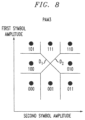
- FIG. 8 illustrates a conventional two-dimensional constellation diagram that may be used to understand the PAM3 mapping methodology.
- the levels of a first received symbol are plotted in the y-axis direction and the levels of a second received symbol are plotted in the x-axis direction.
- a central region of the constellation does not contain any constellation points. Thus, when received samples have values that lie within this region, it is unclear from which transmitted PAM3 constellation point they originated.
- two-dimensional decision boundaries as noted by the diagonal lines D 1 , D 2 in FIG. 8 are required to best determine the constellation point associated with the received symbols.
- An aspect of the use of multiple LLR magnitudes allows for this uncertainty to be taken into consideration when generating an optimum set of LLRs for use by the decoder.
- one premise of the inventive receiver is to maintain a relatively uncomplicated receiver arrangement by using a one-dimensional, hard demapper to process the incoming symbols.
- a one-dimensional hard demapper used with both symbols of the PAM3 data also provides an output of two bits per symbol.
- a similar set of boundary (slicer) levels may be applied to the incoming PAM3 symbols, generating as an output pairs of bits.
- boundary for the case of PAM3, however, a total of four bits (i.e., two consecutive pairs of bits) are needed to perform the LLR generation in accordance with the teachings of the present invention, as described in detail below.
- the PAM3 LLR generation process thus begins by collecting the demapped bits for an associated pair of symbols.
- each symbol represented by each dimension in the diagram of FIG. 8
- FIG. 9 ( a ) illustrates the application of the one-dimensional demapping of PAM4 (as shown in FIG. 3 ) to this two-dimensional constellation.
- a set of three boundary levels is identified for each dimension, allowing for the application of a similar one-dimensional demapping process as used with PAM4 to be applied to each of the symbols used to form a PAM3 constellation point.
- the dimensions are identified as “horizontal” (H) and “vertical” (V).
- a pair of outer boundaries are placed on the two optimal PAM3 decision boundaries in each dimension. This set of four boundaries is shown as H 1 , H 2 , V 1 , and V 2 in FIG. 9 ( a ) .
- a middle boundary is also included along each dimension (shown as H M and V M ) and corresponds to the center PAM3 level.
- the LLRs are determined by considering a demapped region (e.g., 00 00), and considering what is the most likely constellation point from which any samples in this demapped region originate. For the specific outer regions where received samples are uniquely associated with constellation points (shown as shaded in FIG. 9 ( b ) and discussed below with respect to Table I), as well as the regions where one received symbol has a unique association (shown as shaded in FIG. 9 ( c ) ; also see Table II), the result of the consideration is clear and the received samples most likely originate from the corresponding transmitted constellation point. In contrast, when the received samples lie within the central region, it is unclear from which constellation point the samples most likely originate. A methodology for assigning LLR magnitudes for samples associated with this central region will be described below in association with FIGS. 9 ( d ) and ( e ) .
- FIG. 9 ( b ) contains identifications to show the mapping between the PAM4 levels and each symbol in the PAM3 two-dimensional constellation.
- a first conclusion from this illustration is that four corner constellation points (shaded in FIG. 9 ( b ) ) are uniquely associated with only one pair of symbols.
- Table I shows this mapping:
- FIG. 9 ( d ) shows that for each of the four sub-regions delineated by boundaries H M and V M , there is one individual bit that can be known with a high reliability by comparison with its two nearest neighboring constellation points, indicated by the arrows in FIG. 9 ( d ) . That is, for each of the four identified central regions, there is one bit that has the same value as two neighboring constellation points. The other two bits cannot be readily determined in this manner, and are therefore shown by “X” in FIG. 9 ( d ) . Given this combination of “known” and “unknown” values, the LLR generator apparatus of the present invention will function to assign individual magnitudes to each bit the triplet, based on whether it is “known” or “unknown”. Table III illustrates this concept:
- each entry in the central region can be mapped to a designated one of the closest neighbors (in a one-to-one arrangement), as shown in FIG. 9 ( e ) .
- a low LLR magnitude can be used for these less reliable constellation point mappings.
- Table IV is a presentation of this specific mapping as shown in FIG. 9 ( e ) , with the understanding that other one-to-one mappings to neighbors may also be used.
- FIG. 10 illustrates an exemplary PAM3 receiver structure 80 based on the use of a one-dimensional demapper 82 that is used to demap each incoming symbol into a pair of bits, as described above.
- a pair of consecutive symbols are applied as parallel inputs to an LLR generator apparatus 90 .
- apparatus 90 includes at least one processor 92 and at least one memory 94 including computer program code. Also stored in memory 94 is a set of predefined LLR magnitudes (e.g., “HIGH”, “ZERO”, “LOW”, etc.), which are selected by processor 92 to be used in the formation of LLRs for each bit of the set of four bits received by apparatus 90 .
- predefined LLR magnitudes e.g., “HIGH”, “ZERO”, “LOW”, etc.
- LLR generator apparatus 90 provides an output of LLRs at a rate of 75 G LLRs/s for a 100 Gb/s incoming bit stream.
- each output from LLR generator apparatus 90 is a triplet of LLRs (associated with the set of three bits defining a PAM3 symbol), which is thereafter applied as the input LLR value to a conventional LDPC decoder 84 .
- LDPC decoder 84 is used to provide as an output of PAM3 receiver structure 80 the recovered, original data stream.
- the inventive concept of using one-dimensional hard demapping in combination with multiple LLR magnitudes may be used in recovering data from other two-dimensional constellations, as well as higher-order constellations.
- the digital receiver configuration can be generalized by considering a scenario where N bits are being transmitted over M symbols.
- FIGS. 11 and 12 illustrate this generalization by way of DSQ8 mapping, where FIG. 11 shows a conventional two-dimensional constellation (requiring two-dimensional demapping) and FIG. 12 shows a re-creation in an arrangement that may be used with one-dimensional demapping.
- the described examples focus on constellations in which all of the constellation points (and, equivalently, all of the transmitted bits) are transmitted with equal occurrences or probabilities. It is to be understood that the inventive technique also applies to constellation points, and transmitted bits, that are transmitted with unequal probabilities; for instance, when applying probabilistic constellation shaping. In this case, the LLR magnitudes may be derived by also taking into account the prior probabilities with which the bits are being transmitted.
- any block diagrams herein represent conceptual views of illustrative circuitry embodying the principles of the disclosure.
- any flow charts, flow diagrams, state transition diagrams, pseudo code, and the like represent various processes which may be substantially represented in computer readable medium and so executed by a computer or processor, whether or not such computer or processor is explicitly shown.
Landscapes
- Engineering & Computer Science (AREA)
- Physics & Mathematics (AREA)
- Probability & Statistics with Applications (AREA)
- Theoretical Computer Science (AREA)
- Computer Networks & Wireless Communication (AREA)
- Signal Processing (AREA)
- Electromagnetism (AREA)
- Artificial Intelligence (AREA)
- Computing Systems (AREA)
- Digital Transmission Methods That Use Modulated Carrier Waves (AREA)
- Error Detection And Correction (AREA)
Abstract
Description
LLR n=−1b
where LLRinit is a fixed magnitude value.
if b n is MSB,|LLR init |=|A|⇒LLR n=−1b
if b n is LSB,|LLR init |=|B|⇒LLR n=−1b
using the combination of at least one
if b n is MSB and LSB=0,|LLR init |=|A1|, and LLR n=−1b
if b n is MSB and LSB=1,|LLR init |=|A2|, and LLR n=−1b
if bn is LSB,|LLR init |=|A3|, and LLR n=−1b
where A1>A2>A3.
| TABLE I | ||||
| FIRST | SECOND | CONSTELLATION | LLR | |
| SYMBOL | | POINT | MAGNITUDE | |
| 00 | 00 | 000 | ALL HIGH | |
| 10 | 00 | 101 | ALL HIGH | |
| 00 | 10 | 011 | ALL HIGH | |
| 10 | 10 | 110 | ALL HIGH | |
| TABLE II | ||||
| FIRST | SECOND | CONSTELLATION | LLR | |
| SYMBOL | | POINT | MAGNITUDE | |
| 01 | 00 | 100 | |
|
| 11 | 00 | |
||
| 01 | 10 | 010 | |
|
| 11 | 10 | |
||
| 00 | 01 | 001 | |
|
| 00 | 11 | |
||
| 10 | 01 | 111 | |
|
| 10 | 11 | HIGH | ||
| TABLE III | ||||
| FIRST | SECOND | CONSTELLATION | LLR | |
| SYMBOL | | POINT | MAGNITUDE | |
| 01 | 01 | X0X | ZERO, HIGH, ZERO | |
| 11 | 01 | 1XX | HIGH, ZERO, ZERO | |
| 01 | 11 | 0XX | HIGH, ZERO, ZERO | |
| 11 | 11 | X1X | ZERO, HIGH, ZERO | |
These unsure bits may also be treated as erasures, with their LLR magnitude values set to ZERO.
| TABLE IV | ||||
| FIRST | SECOND | CONSTELLATION | LLR | |
| SYMBOL | | POINT | MAGNITUDE | |
| 01 | 01 | 001 | LOW, HIGH, LOW | |
| 11 | 01 | 100 | HIGH. LOW. |
|
| 01 | 11 | 010 | HIGH, LOW. |
|
| 11 | 11 | 111 | LOW, HIGH, LOW | |
Claims (18)
if b n is MSB,|LLR init |=|A|⇒LLR n=−1b
if b n is LSB,|LLR init |=|B|⇒LLR n=−1b
if b n is MSB and LSB=0,|LLR init |=|A1|, and LLR n=−1b
if b n is MSB and LSB=1,|LLR init |=|A2|, and LLR n=−1b
if b n is LSB,|LLR init |=|A3|, and LLR n=−1b
Priority Applications (2)
| Application Number | Priority Date | Filing Date | Title |
|---|---|---|---|
| US17/861,140 US12191995B2 (en) | 2022-07-08 | 2022-07-08 | One-dimensional hard-input FEC receiver for digital communication |
| EP23182260.2A EP4304096B1 (en) | 2022-07-08 | 2023-06-29 | One-dimensional hard-input fec receiver for digital communication |
Applications Claiming Priority (1)
| Application Number | Priority Date | Filing Date | Title |
|---|---|---|---|
| US17/861,140 US12191995B2 (en) | 2022-07-08 | 2022-07-08 | One-dimensional hard-input FEC receiver for digital communication |
Publications (2)
| Publication Number | Publication Date |
|---|---|
| US20240014930A1 US20240014930A1 (en) | 2024-01-11 |
| US12191995B2 true US12191995B2 (en) | 2025-01-07 |
Family
ID=87060114
Family Applications (1)
| Application Number | Title | Priority Date | Filing Date |
|---|---|---|---|
| US17/861,140 Active 2042-11-19 US12191995B2 (en) | 2022-07-08 | 2022-07-08 | One-dimensional hard-input FEC receiver for digital communication |
Country Status (2)
| Country | Link |
|---|---|
| US (1) | US12191995B2 (en) |
| EP (1) | EP4304096B1 (en) |
Citations (6)
| Publication number | Priority date | Publication date | Assignee | Title |
|---|---|---|---|---|
| US20140079394A1 (en) * | 2012-09-15 | 2014-03-20 | Chongjin Xie | Optical Communication Of Interleaved Symbols Associated With Polarizations |
| EP3113436A1 (en) | 2014-02-24 | 2017-01-04 | Mitsubishi Electric Corporation | Soft decision value generation apparatus and soft decision value generation method |
| US10027423B1 (en) * | 2015-06-22 | 2018-07-17 | Inphi Corporation | Adaptive demapper |
| US20220006532A1 (en) * | 2020-06-25 | 2022-01-06 | King Abdullah University Of Science And Technology | Communicating over a free-space optical channel using distribution matching |
| US20220263691A1 (en) * | 2021-02-16 | 2022-08-18 | Nvidia Corporation | Technique to perform demodulation of wireless communications signal data |
| US20230208542A1 (en) * | 2020-06-12 | 2023-06-29 | Intel Corporation | A Concept for a Preamble for a Point to Multipoint Network |
-
2022
- 2022-07-08 US US17/861,140 patent/US12191995B2/en active Active
-
2023
- 2023-06-29 EP EP23182260.2A patent/EP4304096B1/en active Active
Patent Citations (6)
| Publication number | Priority date | Publication date | Assignee | Title |
|---|---|---|---|---|
| US20140079394A1 (en) * | 2012-09-15 | 2014-03-20 | Chongjin Xie | Optical Communication Of Interleaved Symbols Associated With Polarizations |
| EP3113436A1 (en) | 2014-02-24 | 2017-01-04 | Mitsubishi Electric Corporation | Soft decision value generation apparatus and soft decision value generation method |
| US10027423B1 (en) * | 2015-06-22 | 2018-07-17 | Inphi Corporation | Adaptive demapper |
| US20230208542A1 (en) * | 2020-06-12 | 2023-06-29 | Intel Corporation | A Concept for a Preamble for a Point to Multipoint Network |
| US20220006532A1 (en) * | 2020-06-25 | 2022-01-06 | King Abdullah University Of Science And Technology | Communicating over a free-space optical channel using distribution matching |
| US20220263691A1 (en) * | 2021-02-16 | 2022-08-18 | Nvidia Corporation | Technique to perform demodulation of wireless communications signal data |
Non-Patent Citations (5)
| Title |
|---|
| Hyun, K. et al., "Bit Metric Generation for Gray Coded Qam Signals", IEEE Proceedings: Communications, Institution of Electrical Engineers, vol. 152, No. 6, Dec. 9, 2005, pp. 1134-1138. |
| Kang, In-Woong et al., "Low-Complexity LLR Calculation for Gray-Coded PAM Modulation", IEEE Communications Letters, vol. 20, No. 4, Apr. 1, 2016, pp. 688-691. |
| Song et al., "A Normalized LLR Soft Information Demapping Method in DTMB System", IEEE, 2008 (Year: 2008). * |
| Voloshynovskiy et al., "Information—Theoretic Data—Hiding: Recent Achievements And Open Problems", International Journal of Image and Graphics, vol. 5, No. 1, 2005 (Year: 2005). * |
| Zhao, Xue et al., "LDPC-Coded Probabilistic Shaping PAM8 Employing a Novel Bit-Weighted Distribution Matching in WDM-PON", Journal of Lightwave Technology, vol. 38, No. 17, Sep. 1, 2020, pp. 4641-4647. |
Also Published As
| Publication number | Publication date |
|---|---|
| US20240014930A1 (en) | 2024-01-11 |
| EP4304096B1 (en) | 2025-03-26 |
| EP4304096A1 (en) | 2024-01-10 |
Similar Documents
| Publication | Publication Date | Title |
|---|---|---|
| US10659192B2 (en) | Apparatus and method for communicating data over an optical channel | |
| KR100403230B1 (en) | Method and apparatus for iteratively decoding a multilevel modulated signal | |
| KR100491910B1 (en) | Method and apparatus for detecting communication signals having unequal error protection | |
| US8175466B2 (en) | Methods and systems for polarization multiplexed multilevel modulation for optical communication | |
| US5416804A (en) | Digital signal decoder using concatenated codes | |
| WO2001043293A1 (en) | Reduced search symbol estimation algorithm | |
| US20230198670A1 (en) | Method and apparatus for point-to-multi-point communications using combined block and codeword interleaving | |
| KR20140117451A (en) | Method for non-uniform mapping of bit sequences and a corresponding device | |
| Lentner et al. | Concatenated forward error correction with KP4 and single parity check codes | |
| Matsumine et al. | Rate-adaptive concatenated multi-level coding with novel probabilistic amplitude shaping | |
| Vinck | Coding concepts and reed-solomon codes | |
| EP3648378A1 (en) | Method and apparatus for binary signal reception, clock data recovery, and soft decoding | |
| KR102174601B1 (en) | A novel mapping scheme capable of practical error correction implementation for probabilistically shaped intensity-modulation and direct-detection systems | |
| US12191995B2 (en) | One-dimensional hard-input FEC receiver for digital communication | |
| Agrell et al. | Performance prediction recipes for optical links | |
| US7356088B2 (en) | M-dimension M-PAM trellis code system and associated trellis encoder and decoder | |
| US10673563B2 (en) | Modulation method and apparatus | |
| WO2018133938A1 (en) | An apparatus and method for arranging bits for inputting to a channel encoder | |
| Naka | Performance of probabilistic amplitude shaping with a single LUT distribution matcher | |
| CN116248230B (en) | Method and apparatus for downstream transmission | |
| US12081926B2 (en) | Apparatus and a method for transmitting and receiving in a passive optical network | |
| Yoshida et al. | Low-complexity symbol demapping for multidimensional multilevel coded modulation | |
| JP7763315B1 (en) | Error correction method and error correction circuit | |
| Strobel | Error correction coding for passive optical networks | |
| Li | A hybrid analog-digital coding scheme for digital sources |
Legal Events
| Date | Code | Title | Description |
|---|---|---|---|
| FEPP | Fee payment procedure |
Free format text: ENTITY STATUS SET TO UNDISCOUNTED (ORIGINAL EVENT CODE: BIG.); ENTITY STATUS OF PATENT OWNER: LARGE ENTITY |
|
| AS | Assignment |
Owner name: NOKIA SOLUTIONS AND NETWORKS OY, FINLAND Free format text: ASSIGNMENT OF ASSIGNORS INTEREST;ASSIGNOR:NOKIA OF AMERICA CORPORATION;REEL/FRAME:060540/0534 Effective date: 20220513 Owner name: NOKIA SOLUTIONS AND NETWORKS OY, FINLAND Free format text: ASSIGNMENT OF ASSIGNORS INTEREST;ASSIGNOR:NOKIA BELL NV;REEL/FRAME:060540/0527 Effective date: 20220512 Owner name: NOKIA BELL NV, BELGIUM Free format text: ASSIGNMENT OF ASSIGNORS INTEREST;ASSIGNORS:LEFEVRE, YANNICK;VERPLAETSE, MICHIEL;REEL/FRAME:060540/0524 Effective date: 20220503 Owner name: NOKIA OF AMERICA CORPORATION, NEW JERSEY Free format text: ASSIGNMENT OF ASSIGNORS INTEREST;ASSIGNOR:MAHADEVAN, AMITKUMAR;REEL/FRAME:060540/0521 Effective date: 20220502 |
|
| STPP | Information on status: patent application and granting procedure in general |
Free format text: DOCKETED NEW CASE - READY FOR EXAMINATION |
|
| STPP | Information on status: patent application and granting procedure in general |
Free format text: NON FINAL ACTION MAILED |
|
| STPP | Information on status: patent application and granting procedure in general |
Free format text: NON FINAL ACTION MAILED |
|
| STPP | Information on status: patent application and granting procedure in general |
Free format text: RESPONSE TO NON-FINAL OFFICE ACTION ENTERED AND FORWARDED TO EXAMINER |
|
| STPP | Information on status: patent application and granting procedure in general |
Free format text: NOTICE OF ALLOWANCE MAILED -- APPLICATION RECEIVED IN OFFICE OF PUBLICATIONS |
|
| STPP | Information on status: patent application and granting procedure in general |
Free format text: NOTICE OF ALLOWANCE MAILED -- APPLICATION RECEIVED IN OFFICE OF PUBLICATIONS |
|
| STCB | Information on status: application discontinuation |
Free format text: ABANDONED -- FAILURE TO PAY ISSUE FEE |
|
| STPP | Information on status: patent application and granting procedure in general |
Free format text: PUBLICATIONS -- ISSUE FEE PAYMENT RECEIVED |
|
| STPP | Information on status: patent application and granting procedure in general |
Free format text: PUBLICATIONS -- ISSUE FEE PAYMENT VERIFIED |
|
| STCF | Information on status: patent grant |
Free format text: PATENTED CASE |