US12189663B2 - Systems and methods for visualizing object models of database tables - Google Patents
Systems and methods for visualizing object models of database tables Download PDFInfo
- Publication number
- US12189663B2 US12189663B2 US17/307,427 US202117307427A US12189663B2 US 12189663 B2 US12189663 B2 US 12189663B2 US 202117307427 A US202117307427 A US 202117307427A US 12189663 B2 US12189663 B2 US 12189663B2
- Authority
- US
- United States
- Prior art keywords
- visualization
- data
- icon
- data object
- region
- Prior art date
- Legal status (The legal status is an assumption and is not a legal conclusion. Google has not performed a legal analysis and makes no representation as to the accuracy of the status listed.)
- Active, expires
Links
Images


Classifications
-
- G—PHYSICS
- G06—COMPUTING OR CALCULATING; COUNTING
- G06F—ELECTRIC DIGITAL DATA PROCESSING
- G06F3/00—Input arrangements for transferring data to be processed into a form capable of being handled by the computer; Output arrangements for transferring data from processing unit to output unit, e.g. interface arrangements
- G06F3/01—Input arrangements or combined input and output arrangements for interaction between user and computer
- G06F3/048—Interaction techniques based on graphical user interfaces [GUI]
- G06F3/0484—Interaction techniques based on graphical user interfaces [GUI] for the control of specific functions or operations, e.g. selecting or manipulating an object, an image or a displayed text element, setting a parameter value or selecting a range
- G06F3/0486—Drag-and-drop
-
- G—PHYSICS
- G06—COMPUTING OR CALCULATING; COUNTING
- G06F—ELECTRIC DIGITAL DATA PROCESSING
- G06F16/00—Information retrieval; Database structures therefor; File system structures therefor
- G06F16/20—Information retrieval; Database structures therefor; File system structures therefor of structured data, e.g. relational data
- G06F16/22—Indexing; Data structures therefor; Storage structures
- G06F16/2228—Indexing structures
- G06F16/2246—Trees, e.g. B+trees
-
- G—PHYSICS
- G06—COMPUTING OR CALCULATING; COUNTING
- G06F—ELECTRIC DIGITAL DATA PROCESSING
- G06F16/00—Information retrieval; Database structures therefor; File system structures therefor
- G06F16/20—Information retrieval; Database structures therefor; File system structures therefor of structured data, e.g. relational data
- G06F16/23—Updating
- G06F16/2308—Concurrency control
-
- G—PHYSICS
- G06—COMPUTING OR CALCULATING; COUNTING
- G06F—ELECTRIC DIGITAL DATA PROCESSING
- G06F16/00—Information retrieval; Database structures therefor; File system structures therefor
- G06F16/20—Information retrieval; Database structures therefor; File system structures therefor of structured data, e.g. relational data
- G06F16/24—Querying
- G06F16/248—Presentation of query results
-
- G—PHYSICS
- G06—COMPUTING OR CALCULATING; COUNTING
- G06F—ELECTRIC DIGITAL DATA PROCESSING
- G06F16/00—Information retrieval; Database structures therefor; File system structures therefor
- G06F16/20—Information retrieval; Database structures therefor; File system structures therefor of structured data, e.g. relational data
- G06F16/28—Databases characterised by their database models, e.g. relational or object models
- G06F16/284—Relational databases
- G06F16/285—Clustering or classification
- G06F16/287—Visualization; Browsing
-
- G—PHYSICS
- G06—COMPUTING OR CALCULATING; COUNTING
- G06F—ELECTRIC DIGITAL DATA PROCESSING
- G06F16/00—Information retrieval; Database structures therefor; File system structures therefor
- G06F16/20—Information retrieval; Database structures therefor; File system structures therefor of structured data, e.g. relational data
- G06F16/28—Databases characterised by their database models, e.g. relational or object models
- G06F16/289—Object oriented databases
-
- G—PHYSICS
- G06—COMPUTING OR CALCULATING; COUNTING
- G06F—ELECTRIC DIGITAL DATA PROCESSING
- G06F3/00—Input arrangements for transferring data to be processed into a form capable of being handled by the computer; Output arrangements for transferring data from processing unit to output unit, e.g. interface arrangements
- G06F3/01—Input arrangements or combined input and output arrangements for interaction between user and computer
- G06F3/048—Interaction techniques based on graphical user interfaces [GUI]
-
- G—PHYSICS
- G06—COMPUTING OR CALCULATING; COUNTING
- G06F—ELECTRIC DIGITAL DATA PROCESSING
- G06F2203/00—Indexing scheme relating to G06F3/00 - G06F3/048
- G06F2203/048—Indexing scheme relating to G06F3/048
- G06F2203/04806—Zoom, i.e. interaction techniques or interactors for controlling the zooming operation
Definitions
- the disclosed implementations relate generally to data visualization and more specifically to systems and methods that facilitate visualizing object models of a data source.
- Data visualization applications enable a user to understand a data set visually, including distribution, trends, outliers, and other factors that are important to making business decisions.
- Some data visualization applications provide a user interface that enables users to build visualizations from a data source by selecting data fields and placing them into specific user interface regions to indirectly define a data visualization.
- an object model of a data source it can help to construct an object model of a data source before generating data visualizations.
- one person is a particular expert on the data, and that person creates the object model.
- a data visualization application can leverage that information to assist all users who access the data, even if they are not experts. For example, other users can combine tables or augment an existing table or an object model.
- An object is a collection of named attributes.
- An object often corresponds to a real-world object, event, or concept, such as a Store.
- the attributes are descriptions of the object that are conceptually at a 1:1 relationship with the object.
- a Store object may have a single [Manager Name] or [Employee Count] associated with it.
- an object is often stored as a row in a relational table, or as an object in JSON.
- a class is a collection of objects that share the same attributes. It must be analytically meaningful to compare objects within a class and to aggregate over them.
- a class is often stored as a relational table, or as an array of objects in JSON.
- An object model is a set of classes and a set of many-to-one relationships between them. Classes that are related by 1-to-1 relationships are conceptually treated as a single class, even if they are meaningfully distinct to a user. In addition, classes that are related by 1-to-1 relationships may be presented as distinct classes in the data visualization user interface. Many-to-many relationships are conceptually split into two many-to-one relationships by adding an associative table capturing the relationship.
- a data visualization application can assist a user in various ways. In some implementations, based on data fields already selected and placed onto shelves in the user interface, the data visualization application can recommend additional fields or limit what actions can be taken to prevent unusable combinations. In some implementations, the data visualization application allows a user considerable freedom in selecting fields, and uses the object model to build one or more data visualizations according to what the user has selected.
- a method facilitates visually building object models for data sources.
- the method is performed at a computer having one or more processors, a display, and memory.
- the memory stores one or more programs configured for execution by the one or more processors.
- the computer displays, in a connections region, a plurality of data sources. Each data source is associated with a respective one or more tables.
- the computer concurrently displays, in an object model visualization region, a tree having one or more data object icons. Each data object icon represents a logical combination of one or more tables. While concurrently displaying the tree of the one or more data object icons in the object model visualization region and the plurality of data sources in the connections region, the computer performs a sequence of operations.
- the computer detects, in the connections region, a first portion of an input on a first table associated with a first data source in the plurality of data sources. In response to detecting the first portion of the input on the first table, the computer generates a candidate data object icon corresponding to the first table. The computer also detects, in the connections region, a second portion of the input on the candidate data object icon. In response to detecting the second portion of the input on the candidate data object icon, the computer moves the candidate data object icon from the connections region to the object model visualization region. In response to moving the candidate data object icon to the object model visualization and while still detecting the input, the computer provides a visual cue to connect the candidate data object icon to a neighboring data object icon.
- the computer detects, in the object model visualization region, a third portion of the input on the candidate data object icon.
- the computer displays a connection between the candidate data object icon and the neighboring data object icon, and updates the tree of the one or more data object icons to include the candidate data object icon.
- the computer prior to providing the visual cue, performs a nearest object icon calculation that corresponds to the location of the candidate data object icon in the object model visualization region to identify the neighboring data object icon.
- the computer provides the visual cue by displaying a Bézier curve between the candidate data object icon and the neighboring data object icon.
- the computer detects, in the object model visualization region, a second input on a respective data object icon. In response to detecting the second input on the respective data object icon, the computer provides an affordance to edit the respective data object icon. In some implementations, the computer detects, in the object model visualization region, a selection of the affordance to edit the respective data object icon. In response to detecting the selection of the affordance to edit the respective data object icon, the computer displays, in the object model visualization region, a second set of one or more data object icons corresponding to the respective data object icon. In some implementations, the computer displays an affordance to revert to displaying a state of the object model visualization region prior to detecting the second input.
- the computer displays a respective type icon corresponding to each data object icon.
- each type icon indicates if the corresponding data object icon specifies a join, a union, or custom SQL statements.
- the computer detects an input on a first type icon. In response to detecting the input on the first type icon, the computer displays an editor for editing the corresponding data object icon.
- the computer in response to detecting that the candidate data object icon is moved over a first data object icon in the object model visualization region, depending on the relative position of the first data object icon to the candidate data object icon, the computer either replaces the first data object icon with the candidate data object icon or displays shortcuts to combine the first data object icon with the candidate data object icon.
- the computer in response to detecting the third portion of the input on the candidate data object icon, displays one or more affordances to select linking fields that connect the candidate data object icon with the neighboring data object icon.
- the computer detects a selection input on a respective affordance of the one or more affordances.
- the computer updates the tree of the one or more data object icons according to a linking field corresponding to the selection input. In some implementations, a new or modified object model corresponding to the updated tree is saved.
- the input is a drag and drop operation.
- the computer generates the candidate data object icon by displaying the candidate data object icon in the connections region and superimposing the candidate data object icon over the first table.
- the computer concurrently displays, in a data grid region, data fields corresponding to one or more of the data object icons.
- the computer in response to detecting the third portion of the input on the candidate data object icon, the computer updates the data grid region to include data fields corresponding to the candidate data object icon.
- the computer detects, in the object model visualization region, an input to delete a first data object icon.
- the computer removes one or more connections between the first data object icon and other data object icons in the object model visualization region, and updates the tree of the one or more data object icons to omit the candidate data object icon.
- the computer displays a data prep flow icon corresponding to a data object icon, and detects an input on the data prep flow icon. In response to detecting the input on the data prep flow icon, the computer displays one or more steps of the data prep flow, which define a process for calculating data for the data object icon. In some implementations, the computer detects a data prep flow edit input on a respective step of the one or more steps of the data prep flow. In response to detecting the data prep flow edit input, the computer displays one or more options to edit the respective step of the data prep flow. In some implementations, the computer displays an affordance to revert to displaying a state of the object model visualization region prior to detecting the input on the data prep flow icon.
- a method facilitates visualizing object models for data sources.
- the method is performed at a computer having one or more processors, a display, and memory.
- the memory stores one or more programs configured for execution by the one or more processors.
- the computer displays, in an object model visualization region, a first visualization of a tree of one or more data object icons. Each data object icon represents a logical combination of one or more tables. While concurrently displaying the first visualization in the object model visualization region, the computer detects, in the object model visualization region, a first input on a first data object icon of the tree of one or more data object icons.
- the computer In response to detecting the first input on the first data object icon, the computer displays a second visualization of the tree of the one or more data object icons in a first portion of the object model visualization region.
- the computer also displays a third visualization of information related to the first data object icon in a second portion of the object model visualization region.
- the computer obtains the second visualization of the tree of the one or more data object icons by shrinking the first visualization.
- the computer detects a second input on a second data object icon. In response to detecting the second input on the second data object icon, the computer ceases to display the third visualization and displays a fourth visualization of information related to the second data object icon in the second portion of the object model visualization region. In some implementations, the computer resizes the first portion and the second portion according to (i) the size of the tree of the one or more data object icons, and (ii) the size of the information related to the second data object icon. In some implementations, the computer moves the second visualization to focus on the second data object icon in the first portion of the object model visualization region.
- the computer displays, in the object model visualization region, one or more affordances to select filters to add to the first visualization.
- the computer displays, in the object model visualization region, recommendations of one or more data sources to add objects to the tree of one or more data object icons.
- the computer prior to displaying the second visualization and the third visualization, segments the object model visualization region into the first portion and the second portion according to (i) the size of the tree of the one or more data object icons, and (ii) the size of the information related to the first data object icon.
- the computer prior to displaying the second visualization and the third visualization, the computer generates a fourth visualization of information related to the first data object icon.
- the computer displays the fourth visualization by superimposing the fourth visualization over the first visualization while concurrently shrinking and moving the first visualization to the first portion in the object model visualization region.
- the computer successively grows and/or moves the fourth visualization to form the third visualization in the second portion in the object model visualization region.
- the information related to the first data object icon includes a second tree of one or more data object icons.
- the computer detects a third input in the second portion of the object model visualization region, away from the second visualization. In response to detecting the third input, the computer reverts to display the first visualization in the object model visualization region. In some implementations, reverting to display the first visualization in the object model visualization region includes ceasing to display the third visualization in the second portion of the object model visualization region, and successively growing and moving the second visualization to form the first visualization in the object model visualization region.
- a system for generating data visualizations includes one or more processors, memory, and one or more programs stored in the memory.
- the programs are configured for execution by the one or more processors.
- the programs include instructions for performing any of the methods described herein.
- a non-transitory computer readable storage medium stores one or more programs configured for execution by a computer system having one or more processors and memory.
- the one or more programs include instructions for performing any of the methods described herein.
- FIG. 1 A illustrates conceptually a process of building an object model in accordance with some implementations.
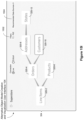
- FIG. 1 B illustrates conceptually a process of building a data visualization based on an object model in accordance with some implementations.
- FIG. 2 is a block diagram of a computing device according to some implementations.
- FIGS. 3 , 4 A, 4 B, 5 A- 5 G, 6 A- 6 F, 7 A- 7 G, 8 A- 8 J, 9 A- 9 G, 10 A- 10 E , and 11 A- 11 D are screen shots illustrating various features of some disclosed implementations.
- FIGS. 12 A- 12 L and 13 A- 13 F illustrate techniques for providing visual cues in an interactive application for creation and visualization of object models, in accordance with some implementations.
- FIGS. 14 A- 14 J provide a flowchart of a method for forming object models, in accordance with some implementations.
- FIGS. 15 A- 15 J are screen shots illustrating various features of some disclosed implementations.
- FIG. 16 provides a flowchart of a method for visualizing object models, in accordance with some implementations.
- FIG. 1 A illustrates conceptually a process of building an object model 106 for data sources 102 using a graphical user interface 104 , in accordance with some implementations.
- the object model 106 applies to one data source (e.g., one SQL database or one spreadsheet file), but the object model 106 may encompass two or more data sources. Typically, unrelated data sources have distinct object models.
- the object model closely mimics the data model of the physical data sources (e.g., classes in the object model corresponding to tables in a SQL database). However, in some cases the object model 106 is more normalized (or less normalized) than the physical data sources.
- the object model 106 groups together attributes (e.g., data fields) that have a one-to-one relationship with each other to form classes, and identifies many-to-one relationships among the classes. In the illustrations below, the many-to-one relationships are illustrated with the “many” side of each relationship horizontally to the left of the “one” side of the relationship. The object model 106 also identifies each of the data fields (attributes) as either a dimension or a measure.
- attributes e.g., data fields
- the letter “D” (or “d”) is used to represent a dimension (e.g., a categorical data field, typically having a string data type), whereas the latter “M” (or “m”) is used to represent a measure (e.g., a numeric data field that can be summed or averaged).
- the object model 106 When the object model 106 is constructed, it can facilitate building data visualizations based on the data fields a user selects. Because a single data model can be used by an unlimited number of other people, building the object model for a data source is commonly delegated to a person who is a relative expert on the data source.
- Some implementations allow a user to compose an object by combining multiple tables. Some implementations allow a user to expand an object via a join or a union with other objects. Some implementations provide drag-and-drop analytics to facilitate building an object model. Some implementations facilitate snapping and/or connecting objects or tables to an object model. These techniques and other related details are explained below in reference to FIGS. 3 - 14 J , according to some implementations.
- the visual specification identifies one or more data sources 102 , which may be stored locally (e.g., on the same device that is displaying the user interface 108 ) or may be stored externally (e.g., on a database server or in the cloud).
- the visual specification 110 also includes visual variables.
- the visual variables specify characteristics of the desired data visualization indirectly according to selected data fields from the data sources 102 .
- a user assigns zero or more data fields to each of the visual variables, and the values of the data fields determine the data visualization that will be displayed.
- the visual variables In most instances, not all of the visual variables are used. In some instances, some of the visual variables have two or more assigned data fields. In this scenario, the order of the assigned data fields for the visual variable (e.g., the order in which the data fields were assigned to the visual variable by the user) typically affects how the data visualization is generated and displayed.
- the data visualization application 234 groups ( 112 ) together the user-selected data fields according to the object model 106 .
- Such groups are called data field sets.
- all of the user-selected data fields are in a single data field set.
- Each measure m is in exactly one data field set, but each dimension d may be in more than one data field set.
- the data visualization application 234 queries ( 114 ) the data sources 102 for the first data field set, and then generates a first data visualization 118 corresponding to the retrieved data.
- the first data visualization 118 is constructed according to the visual variables in the visual specification 110 that have assigned data fields from the first data field set. When there is only one data field set, all of the information in the visual specification 110 is used to build the first data visualization 118 . When there are two or more data field sets, the first data visualization 118 is based on a first visual sub-specification consisting of all information relevant to the first data field set. For example, suppose the original visual specification 110 includes a filter that uses a data field f. If the field f is included in the first data field set, the filter is part of the first visual sub-specification, and thus used to generate the first data visualization 118 .
- the data visualization application 234 queries ( 116 ) the data sources 102 for the second (or subsequent) data field set, and then generates the second (or subsequent) data visualization 120 corresponding to the retrieved data.
- This data visualization 120 is constructed according to the visual variables in the visual specification 110 that have assigned data fields from the second (or subsequent) data field set.
- FIG. 2 is a block diagram illustrating a computing device 200 that can execute the data visualization application 234 to display a data visualization 118 (or the data visualization 120 ).
- the computing device displays a graphical user interface 108 for the data visualization application 234 .
- Computing devices 200 include desktop computers, laptop computers, tablet computers, and other computing devices with a display and a processor capable of running a data visualization application 234 .
- a computing device 200 typically includes one or more processing units/cores (CPUs) 202 for executing modules, programs, and/or instructions stored in the memory 206 and thereby performing processing operations; one or more network or other communications interfaces 204 ; memory 206 ; and one or more communication buses 208 for interconnecting these components.
- CPUs processing units/cores
- a computing device 200 includes a user interface 210 comprising a display 212 and one or more input devices or mechanisms.
- the input device/mechanism includes a keyboard 216 ; in some implementations, the input device/mechanism includes a “soft” keyboard, which is displayed as needed on the display 212 , enabling a user to “press keys” that appear on the display 212 .
- the display 212 and input device/mechanism comprise a touch screen display 214 (also called a touch sensitive display or a touch surface).
- the display is an integrated part of the computing device 200 . In some implementations, the display is a separate display device.
- the computing device 200 includes an audio output device 218 (e.g., a speaker) and/or an audio input device 220 (e.g., a microphone).
- the memory 206 includes high-speed random-access memory, such as DRAM, SRAM, DDR RAM or other random-access solid-state memory devices.
- the memory 206 includes non-volatile memory, such as one or more magnetic disk storage devices, optical disk storage devices, flash memory devices, or other non-volatile solid-state storage devices.
- the memory 206 includes one or more storage devices remotely located from the CPUs 202 .
- the memory 206 or alternatively the non-volatile memory devices within the memory 206 , comprises a non-transitory computer-readable storage medium.
- the memory 206 , or the computer-readable storage medium of the memory 206 stores the following programs, modules, and data structures, or a subset thereof:
- Each of the above identified executable modules, applications, or set of procedures may be stored in one or more of the previously mentioned memory devices, and corresponds to a set of instructions for performing a function described above.
- the above identified modules or programs i.e., sets of instructions
- the memory 206 stores a subset of the modules and data structures identified above.
- the memory 206 stores additional modules or data structures not described above.
- FIG. 2 shows a computing device 200
- FIG. 2 is intended more as functional description of the various features that may be present rather than as a structural schematic of the implementations described herein. In practice, and as recognized by those of ordinary skill in the art, items shown separately could be combined and some items could be separated.
- FIG. 3 shows a screen shot of an example user interface 104 used for creating and/or visualizing object models, in accordance with some implementations.
- the user interface 104 includes a connections region 302 that displays data sources.
- the connections region 302 provides connections 314 to database servers that host databases 316 (or data sources).
- Each data source includes one or more tables of data 318 that may be selected and used to build an object model.
- the list of tables are grouped (e.g., according to a logical organization of the tables).
- the graphical user interface 104 also includes an object model visualization region 304 .
- the object model visualization region 304 displays object models (e.g., a tree or a graph of data objects).
- the object model displayed includes one or more data object icons (e.g., the icons 320 - 2 , 320 - 4 , 320 - 6 , 320 - 8 , 320 - 10 , and 320 - 12 ).
- Each data object icon in turn represents either a table (e.g., a physical table) or a logical combination of one or more tables.
- the icon 320 - 2 represents a Line Items table
- the icon 320 - 12 represents a States table.
- the interface 104 also includes a data grid region 306 , which displays data fields of one or more data object icons displayed in the object model visualization region 304 .
- the grid region 306 is updated or refreshed in response to detecting a user input in the object model visualization region 304 .
- the visualization region 304 shows the object icon 320 - 2 highlighted and the grid region 306 displaying details (e.g., data fields) of the Line Items table corresponding to the object icon 320 - 2 .
- the grid region shows a first table (e.g., the root of a tree of logical tables or object model) to start with (e.g., when a preexisting object model is loaded, as explained further below in reference to FIG. 4 A ), without detecting a user input.
- the grid region is updated to show details of the logical table (or physical table) corresponding to the alternative object icon (e.g., details of the Orders table).
- FIGS. 4 A and 4 B are screen shots of the example user interface 104 for creating a new object model, in accordance with some implementations.
- FIG. 4 A corresponds to the situation where the object model visualization region 304 is displaying an object model, and a user navigates (e.g., moves or drags a cursor) to select an affordance 402 for a new data source.
- the affordance 402 is an option displayed as part of a pull-down menu 404 of available object models.
- FIG. 4 B is a screen shot that illustrates the state of the object model visualization region 304 after a user has selected to create a new object model, in accordance with some implementations.
- the visualization region 304 is initially empty or does not shown any object icons.
- the data grid region 306 is also cleared to not show any data fields.
- FIGS. 5 A- 5 G are screen shots that illustrate a process for creating object models using the example user interface, in accordance with some implementations. Similar to FIG. 4 A , a user starts with a clear canvas in the visualization region 304 . When the user selects one of the tables in the connections region 302 , the system generates a candidate object icon 502 . Some implementations create a shadow object (e.g., a rectangular object) and superimpose the object over or on the table selected by the user. In FIG. 5 A , the user selects the Line Items table, so a new (candidate) object icon (the rectangular shadow object) is created for that table.
- a shadow object e.g., a rectangular object
- FIG. 5 B is a screen shot that shows the user has moved or dragged the icon 502 from the connections region 302 to the object model visualization region 304 , in accordance with some implementations.
- FIG. 5 C is a screen shot that illustrating that the user has moved or dragged the icon 502 to the visualization region 304 (as indicated by the position 504 of the cursor or arrow) in the object model visualization region 304 , in accordance with some implementations. Since the icon 502 moved to the visualization region 302 is the first such icon, the system automatically identifies the table (Line Items) as the root of a new object model tree. In some implementations, the data grid region 306 is automatically refreshed to display data for the data fields of the table corresponding to the object icon (the Line Items table in this example).
- the screen shot illustrates that the user has selected the Orders table in the connections region 302 . Similar to FIG. 5 A , the system responds by creating another candidate object icon 506 for the Orders table.
- the icon 506 is moved to the visualization region 304 and the system recognizes that the visualization region 304 is already displaying an object model (with the Line Items object icon 502 ).
- the system begins displaying a visual cue 508 (e.g., a Bézier curve) prompting the user to add the Orders table (or icon 506 ) to the object model by associating the Orders table with the Line Items table (or the corresponding object icon 502 ). Details on how the visual cues are generated are described below in reference to FIGS. 12 A- 12 L and 13 A- 13 F , according to some implementations.
- the visual cue 508 is adjusted appropriately (e.g., the Bézier curve shortens in FIG. 5 F and lengthens in FIG. 5 G ) to continue to show a possible association with a neighboring object icon (the root object Line Items table, in this case), according to some implementations.
- the system links the object icon 502 with the candidate object icon 506 to create a new object model, according to some implementations.
- FIGS. 6 A- 6 E are screen shots that illustrate a process for establishing relationships between data objects of an object model created using the example user interface 104 , in accordance with some implementations.
- FIG. 6 A illustrates a screen shot of the interface with the visualization region 304 displaying the object model created as described above in FIG. 5 G with the Line Items table (the icon 502 ) and the Orders table (the icon 506 ).
- the dashed line 602 indicates that the two tables (object icons 502 and 506 ) have not yet been joined by a relationship.
- the user interface indicates that Line Items is the “many” side 604 and that Orders represents the “one” side 606 of a relationship to be identified.
- the choices for the foreign keys 608 (FKs) as well as the primary keys 610 (PK) are displayed for user selection.
- FIG. 6 B illustrates a screen shot of the interface 104 after the user selects a relationship, according to some implementations.
- the user selected to link the two tables using Order ID.
- Some implementations provide an affordance 616 for the user to further link other fields between the two tables.
- Some implementations also refresh or update the data grid region 306 to display the tables aligned on the basis of the relationship or key selected by the user (e.g., Order ID).
- the display when the user clicks away (or drags the cursor away) from the portion of the visualization region 304 in FIG. 6 B for selecting keys, to position 618 , the display reverts to the object model with the icons 502 and 506 connected by a solid line 602 to indicate the established link between the two tables.
- Some implementations update the data grid region 306 to indicate the data fields for the root object icon for the object model (icon 502 corresponding to the Line Items table, in this example).
- FIG. 6 D is a screen shot illustrating that the user has selected a different object icon (icon 506 in this example) by moving the cursor to a new position 620 .
- the data grid region 306 is automatically refreshed or updated to show the data fields of the selected object icon (e.g., data fields of the Orders table).
- FIG. 6 E illustrates how the actual join can be constructed and/or validated in some implementations.
- two tables Addresses 622 and Weather 630 are joined ( 638 ) by the user.
- Some implementations indicate the field names (sometimes called linking fields) for the join (e.g., the field City 624 from the Addresses table 622 and the field cityname 632 from the Weather table 630 ).
- the field names sometimes called linking fields
- tables may have more than one linking field.
- Some implementations provide an option 636 to match another field or indicate ( 628 ) that the user could make a unique linking field by adding another matching field or by changing the current fields. Some implementations also indicate the number (or percentage) of records (the indicators 626 and 634 ) that are unique (for each table) when using the current user-selected fields for the join.
- FIG. 6 F illustrates a Relationship Summary window, which provides data about the join between the Line Items table 502 and the Orders table 506 .
- the left side 644 of the graphic is the Many side 640 (Line Items 502 ) and the right side 646 is the One side 642 (Orders 506 ).
- the Relationship Summary indicates the number of rows from the Many side 640 that are matched (20K rows) and unmatched (10K rows).
- the Relationship Summary also indicates the number of rows from the One side 642 that are uniquely matched (39% of the rows) and the number of rows from the One side 642 that have two or more matches (61% of the rows). Having duplicate matches indicates a non-unique join (i.e., a row from Line Items should match to exactly one row from Orders).
- the graphic also shows the number 648 of rows from the Line Items table 502 that uniquely match rows from the Orders table 506 as well as the number 650 of rows from the Line Items table 502 that match two or more rows from the Orders table 506 .
- FIGS. 7 A- 7 G are screen shots that illustrate a process for editing components of an object model using the example user interface, in accordance with some implementations.
- FIG. 7 A continues the example shown in FIG. 6 D where the user selected the object icon 506 .
- the visualization region 304 is updated to zoom in on the object icon 506 .
- the focus is shifted to the Orders table or object icon 506 , according to some implementations.
- the display indicates ( 702 ) that the Orders object icon 506 is made from one table (the Orders table), according to some implementations.
- the system creates a candidate object icon 704 which the user drags towards the object model visualization region 304 .
- the system responds by providing an affordance or option 706 to union the Orders table (object icon 506 ) with the Southern States table corresponding to the candidate object icon 704 , according to some implementations.
- the system displays options 710 for joining the two tables (e.g., inner, left, right, or full outer joins), according to some implementations. Subsequently, after the user has selected one of the join options, the system joins the tables (with an inner join in this example). In some implementations, the system updates the display to indicate ( 712 ), as shown in FIG. 7 E , that the Orders object is now made of two tables (the Orders table and the Southern States table corresponding to the icon 704 ).
- the object icon 506 is updated to indicate ( 714 ) that the object is now a join object (made by joining the two tables Orders and Southern States).
- the user can select the Orders object icon 506 to examine the contents of the Orders object, as shown in FIG. 7 G .
- the user can revert to the parent object model (shown in FIG. 7 F ) by clicking (or double-clicking) on (or selecting) an affordance or option (e.g., the revert symbol icon 716 ) in the visualization region 304 .
- FIGS. 8 A- 8 J are screen shots that illustrate examples of visual cues provided while creating object models using the example user interface, in accordance with some implementations.
- a user begins with the example object model in FIG. 3 , as reproduced in the model visualization shown in FIG. 8 A .
- the user selects the Weather table from the connections region 302 to add to the object model shown in the visualization region 304 .
- the system creates a candidate object icon 802 for the Weather object and begins showing a visual cue 804 indicating possible connections to neighboring object icons, as shown in FIG. 8 B .
- the visual cue 804 indicates that the candidate object icon 802 could be connected to the object icon 320 - 2 .
- the system automatically adjusts the visual cue 804 and/or highlights a neighboring object icon (e.g., the object icon 320 - 2 in FIG. 8 B , the object icon 320 - 6 in FIG. 8 C , and the object icon 320 - 6 in FIG. 8 D ), according to some implementations.
- Some implementations determine the neighboring object icon based on proximity to the candidate object icon.
- Some implementations determine and/or indicate valid, invalid, and/or probable object icons to associate the candidate object icon with. For example, some implementations determine probable neighbors based on known or predetermined relationships between the objects. As illustrated in FIG. 8 E , the user can drag back the candidate object icon 802 to the object icon 320 - 6 , and when the candidate object icon is close to or on top of the object icon 320 - 6 , the system responds by showing an option 806 to union the two objects 320 - 6 and 802 , according to some implementations.
- FIG. 8 F illustrates a screen shot where the candidate object icon 802 is combined by a union 806 with the object corresponding to the object icon 320 - 6 , according to some implementations.
- FIG. 8 G shows the visual cue 804 , as illustrated in FIG. 8 G , according to some implementations.
- the union with the previous object icon (the object icon 320 - 6 in this example) is reverted prior to adjusting the visual cue 804 .
- FIGS. 8 H, 8 I, and 8 J further illustrate examples of adjustments of the visual cue 804 as the user drags the candidate object icon 802 closer to various object icons in the visualization region 304 , according to some implementations.
- FIGS. 9 A- 9 G are screen shots that illustrate visualizations of components of an object model created using the example user interface 104 , in accordance with some implementations.
- a user begins with the example object model in the visualization shown in FIG. 9 A .
- the user can examine each component of the object model in the visualization region 304 by selecting (e.g., moving the cursor over, and/or clicking) an object icon.
- the user selects the object icon 320 - 6 .
- the system displays (e.g., zooms in on) the object icon 320 - 6 (corresponding to the Products object), as shown in FIG. 9 B , according to some implementations.
- the Products object is made ( 906 ) by (inner) joining ( 904 ) the Products table 902 and the Product attributes table 908 .
- FIG. 9 C is a screen shot illustrating that the States object is made ( 911 ) from two tables as indicated by the object icon 910 .
- FIG. 9 D is a screen shot of an example illustration of displaying details of an object icon (the States object icon 320 - 12 in this example), according to some implementations. In some implementations, a user can see the details 912 of an object icon from the object model visualization region 304 while displaying the object model without zooming in on the object icon.
- the Orders object (corresponding to the object icon 320 - 4 ) is a custom SQL object as indicated by the details 914 .
- the details 914 can be edited or customized further by the user.
- the query 918 can be edited by the user, the results of the query can be previewed by selecting an affordance 916 , and/or parameters for the query can be inserted by selecting another affordance 920 , according to some implementations.
- the user can cancel or revert back from the edit interface using an affordance 921 to cancel operations or by selecting a confirmation affordance (e.g., an OK button 922 ), according to some implementations.
- FIGS. 9 F and 9 G components of an object model can be extended or edited further (e.g., new objects added or old objects deleted).
- the States object 910 is made of two tables (as indicated by the indicator 911 ). It is joined with the Orders table (object icon 924 ).
- FIG. 9 G illustrates an updated model visualization in the visualization region 304 for the States object (e.g., indicating ( 926 ) that the States object is now made from 3 tables instead of 2 tables, as shown in FIG. 9 F ).
- FIGS. 10 A- 10 E are screen shots that illustrate an alternative user interface 104 for creating and visualizing object models, in accordance with some implementations.
- the object model visualization region 304 displays an object model using circles or ovals (or any similar shapes, such as rectangles). Each icon corresponds to a respective data object (e.g., the objects 320 - 2 , 320 - 4 , and 1002 , in this example), connected by edges.
- the data grid region 306 is empty initially.
- the object when the user selects an object icon (the Orders object 320 - 4 in this example), the object is highlighted or emphasized, and/or one or more options or affordances 1004 to edit or manipulate the object is displayed to the user, according to some implementations.
- the data grid region 306 is updated to display the details of the selected object.
- the high-level object diagram of the object (the Orders object 320 - 4 ) is displayed in the visualization region 304 , according to some implementations.
- a user can examine the contents of components of the object (e.g., the Returns table 1006 in the Orders object in FIG. 10 D ).
- the data grid region 306 is updated accordingly.
- a user can revert back from the component object (e.g., zoom out) to the parent object model by clicking away from the object (e.g., click at a position 1008 ), according to some implementations.
- Some implementations allow users to disassemble or delete one or more objects from an object model. For example, a user can drag an object icon out of or away from an object model and the corresponding object is removed from the object model.
- Some implementations automatically adjust the object model (e.g., fix up any connections from or to the removed object, and chain the other objects in the object model).
- FIGS. 11 A- 11 D are screen shots that illustrate a process for editing objects that are made from data preparation flows using the alternative user interface 104 , in accordance with some implementations.
- Some implementations provide an option or an affordance (e.g., the circle region 1102 ) to view and/or edit data preparation flows corresponding to data objects. For example, when the user selects (e.g., clicks) the option 1102 in FIG. 11 A , the display in the visualization region 304 refreshes or updates to show the details of the data preparation flow for the Orders object, as shown in FIG. 11 B , according to some implementations.
- the user can edit or modify steps of the data preparation flow (e.g., modify a union or cleaning processes in the flow).
- steps of the data preparation flow e.g., modify a union or cleaning processes in the flow.
- FIGS. 12 A- 12 L and 13 A- 13 F illustrate techniques for providing visual cues in an interactive application for creation and visualization of object models, in accordance with some implementations.
- FIG. 12 A shows an example of a ghost object 1202 that is generated when a user selects a table to add to an object model.
- the user can drag the object 1202 onto (or towards) an object model visualization region.
- Some implementations use distinct styles or dimensions for different types of objects (e.g., a first type for an object that is made of one table and another type for an object that is made of multiple tables).
- the ghost object is placed at an offset (e.g., an offset of 6 pixels vertically and 21 pixels horizontally) relative to the mouse position (or the cursor).
- FIGS. 12 C- 12 H illustrate heuristics for determining a neighboring object to attach a visual cue (e.g., a noodle object).
- a visual cue e.g., a noodle object.
- FIG. 12 C some implementations identify all of the objects to the “left” of the cursor.
- an object is considered “left” of the cursor if the mouse is to the right of its horizontal threshold as illustrated in FIG. 12 C .
- the leftmost object in the graph is considered “left” of the cursor and does not need the calculation shown in FIG. 12 C .
- an object's distance from the cursor is calculated based on its left and middle point, while including a vertical offset.
- some implementations determine the closest object (sometimes called the neighboring object icon), as illustrated further in FIG. 12 E , according to some implementations. Some implementations render a visual cue (e.g., a noodle) to the closest object, as illustrated in FIG. 12 F . Some implementations also style (e.g., highlight, emphasize, add color to) the closest object. In some implementations, the noodle or the visual cue renders differently if an end point is to the left or to the right of a start point. Some implementations use a double Bézier curve if the end point is to the left of the start point. As illustrated in FIG.
- some implementations use either a single Bézier curve or a double Bezier curve if the end point equals the start point. Some implementations use a single Bézier curve if the end point is to the right of the start point, as illustrated in FIG. 12 H .
- FIGS. 12 I- 12 L illustrate an example method for generating double Bézier curves, according to some implementations.
- the method determines a start point, a mid-point, and an end point.
- FIG. 12 J illustrates an example method for generating single Bézier curves, according to some implementations.
- Some implementations use the techniques illustrated in FIG. 12 K to draw the first curve, and/or use the techniques illustrated in FIG. 12 L to draw the second curve of a double Bézier curve.
- FIGS. 13 A- 13 F further illustrate techniques for providing visual cues, according to some implementations.
- the user interface displays an option to UNION the new object with the existing object. If the new object is outside of the revealer area, the user interface displays a noodle connector, indicating the option to JOIN the objects.
- the size of the revealer area can be adapted to encourage either UNIONs or JOINs. This is illustrated in FIG. 13 A .
- an invisible revealer area is dedicated to showing a union drop target, as illustrated in FIG. 13 A .
- the noddle is hidden and the system begins a drop target reveal process, according to some implementations.
- a union or link appear more or less often depending on the revealer's dimensions.
- FIGS. 13 B and 13 C when the mouse enters the revealer area, the system waits for a predetermined delay (e.g., a few seconds) before hiding the noodle and showing the union target.
- FIG. 13 B illustrates when a user is dragging the candidate object icon (for the Adventure Products object), and
- FIG. 13 C illustrates the delay.
- the union target appears after a timer of a predetermined union delay (e.g., a few milliseconds) completes.
- dragging an item outside of the revealer area before the predetermined union delay resets and cancels the timer if the timer has not completed.
- FIG. 13 D illustrates when the union is revealed.
- FIGS. 13 E and 13 F illustrate some of the tunable parameters in some implementations.
- the parameters are interdependent variables, and each parameter is adjusted for an overall look and feel.
- the tunable parameters include, in various implementations, object width, horizontal threshold, horizontal and/or vertical spacing between objects, revealer top/bottom and/or right/left padding, vertical offset, mouse horizontal/vertical offsets, and/or union delay in milliseconds.
- FIGS. 14 A- 14 J provide a flowchart 1400 of a method for forming ( 1402 ) object models according to the techniques described above, in accordance with some implementations.
- the method 1400 is performed ( 1404 ) at a computing device 200 having one or more processors and memory.
- the memory stores ( 1406 ) one or more programs configured for execution by the one or more processors.
- the computer displays ( 1408 ), in a connections region (e.g., the region 318 ), a plurality of data sources. Each data source is associated with a respective one or more tables.
- the computer concurrently displays ( 1410 ), in an object model visualization region (e.g., the region 304 ), a tree of one or more data object icons (e.g., the object icons 320 - 2 , . . . , 320 - 12 in FIG. 3 ). Each data object icon represents a logical combination of one or more tables. While concurrently displaying the tree of the one or more data object icons in the object model visualization region and the plurality of data sources in the connections region, the computer performs ( 1412 ) a sequence of operations.
- the computer detects ( 1414 ), in the connections region, a first portion of an input on a first table associated with a first data source in the plurality of data sources.
- the input includes a drag and drop operation.
- the computer In response to detecting the first portion of the input on the first table, the computer generates ( 1416 ) a candidate data object icon corresponding to the first table.
- the computer generates the candidate data object icon by displaying ( 1418 ) the candidate data object icon in the connections region and superimposing the data object icon over the first table.
- the computer also detects ( 1420 ), in the connections region, a second portion of the input on the candidate data object icon. In response to detecting the second portion of the input on the candidate data object icon, the computer moves ( 1422 ) the candidate data object icon from the connections region to the object model visualization region.
- the computer in response to moving the candidate data object icon to the object model visualization region and while still detecting the input, provides ( 1424 ) a visual cue to connect to a neighboring data object icon.
- the computer prior to providing the visual cue, performs ( 1426 ) a nearest object icon calculation, which corresponds to the location of the candidate data object icon in the object model visualization region, to identify the neighboring data object icon.
- the computer provides the visual cue by displaying ( 1428 ) a Bézier curve between the candidate data object icon and the neighboring data object icon.
- the computer detects ( 1430 ), in the object model visualization region, a third portion of the input on the candidate data object icon.
- the computer displays ( 1434 ) a connection between the candidate data object icon and the neighboring data object icon, and updates ( 1436 ) the tree of the one or more data object icons to include the candidate data object icon.
- the computer detects ( 1438 ), in the object model visualization region, a second input on a respective data object icon.
- the computer provides ( 1440 ) an affordance to edit the respective data object icon.
- the computer detects ( 1442 ), in the object model visualization region, selection of the affordance to edit the respective data object icon.
- the computer displays ( 1444 ), in the object model visualization region, a second one or more data object icons corresponding to the respective data object icon.
- the computer displays ( 1446 ) an affordance to revert to displaying the state of the object model visualization region prior to detecting the second input.
- the computer displays ( 1448 ) a respective type icon corresponding to each data object icon.
- each type icon indicates whether the corresponding data object icon specifies a join, a union, or custom SQL statements.
- the computer detects ( 1450 ) an input on a first type icon. In response to detecting the input on the first type icon, the computer displays an editor for editing the corresponding data object icon.
- the computer in response to detecting that the candidate data object icon is moved over a first data object icon in the object model visualization region, depending on the relative position of the first data object icon with respect to the candidate data object icon, the computer either replaces ( 1452 ) the first data object icon with the candidate data object icon or displays ( 1452 ) shortcuts to combine the first data object icon with the candidate data object icon.
- the computer in response to detecting the third portion of the input on the candidate data object icon, displays ( 1454 ) one or more affordances to select linking fields that connect the candidate data object icon with the neighboring data object icon.
- the computer detects ( 1456 ) a selection input on a respective affordance of the one or more affordances.
- the computer updates ( 1458 ) the tree of the one or more data object icons according to a linking field corresponding to the selection input.
- the computer saves a new or updated object model corresponding to the updated tree.
- the computer concurrently displays ( 1460 ), in a data grid region, data fields corresponding to the candidate data object icon.
- the computer in response to detecting the third portion of the input on the candidate data object icon, the computer updates ( 1462 ) the data grid region to display data fields corresponding to the updated tree of the one or more data object icons.
- the computer detects ( 1464 ), in the object model visualization region, an input to delete a first data object icon.
- the computer removes ( 1466 ) one or more connections between the first data object icon and other data object icons in the object model visualization region, and updates the tree of the one or more data object icons to omit the first data object icon.
- the computer displays ( 1468 ) a data prep flow icon corresponding to a first data object icon, and detects ( 1470 ) an input on the data prep flow icon.
- the computer displays ( 1472 ) one or more steps of the data prep flow, which define a process for calculating data for the first data object icon.
- the computer detects ( 1474 ) a data prep flow edit input on a respective step of the one or more steps of data prep flow.
- the computer displays ( 1476 ) one or more options to edit the respective step of the data prep flow.
- the computer displays ( 1478 ) an affordance to revert to displaying the state of the object model visualization region prior to detecting the input on the data prep flow icon.
- FIGS. 15 A- 15 J are screen shots that illustrate an alternative user interface 104 for visualizing object models, in accordance with some implementations.
- an object model visualization region 304 displays an object model using circles or ovals (or any similar shapes, such as rounded rectangles, as shown in FIG. 15 A ). Each icon corresponds to a respective data object (e.g., the objects 320 - 2 , 320 - 4 , 320 - 6 , 320 - 8 , 320 - 10 , and 320 - 12 ), connected by edges.
- the object model visualization region 304 also shows one or more options for adjusting filters 1502 and/or recommended data sources 1504 . Suppose the cursor is initially positioned at point 1506 .
- the object when the user selects an object icon (the Customers object 320 - 10 in this example), the object is highlighted or emphasized. Although not shown, some implementations provide one or more options or affordances to edit or manipulate the object.
- the user selects an object (e.g., by clicking while positioning the cursor on the object icon), as illustrated in the screen shot in FIG. 15 B .
- the high-level object diagram of the object (the Customers object 320 - 10 ) is displayed in the visualization region 304 , according to some implementations.
- some implementations split or segment the object model visualization region 304 into multiple portions or sub-regions (e.g., a first portion 1508 and a second portion 1510 ). Some implementations determine sizes of (or proportional spaces for) the portions or sub-regions based on predetermined thresholds, and/or sizes of visualizations to be shown in the different portions.
- Some implementations shrink the visualization (of the higher-level model) shown in the first portion. Some implementations show an enlarged visualization in the second portion of the object model visualization region. For example, in FIG. 15 C , the visualization shown in FIGS. 15 A and 15 B is shrunk and displayed in the first portion 1508 . Details of the Customers object 320 - 10 are shown in the second portion 1510 . The Customers object 320 - 10 is shown to be built by joining ( 1514 ) an Addresses table 1512 with a Reward Points Data table/object 1516 .
- FIG. 15 D suppose the user selects the Products object 320 - 6 (as indicated by the position of the cursor 1506 ).
- the second portion 1510 is updated to show details of the Products object 320 - 6 using another visualization 1518 .
- Some implementations adjust the display of the visualization (e.g., move the display of the object model) in the first portion 1508 so as to focus on the object (the Products object 320 - 6 , in this example) selected by the user.
- 15 E, 15 F, and 15 G similarly, show updates to the second portion (via the visualizations 1520 , 1522 , and 1524 , respectively) when the user selects the Orders object 320 - 4 , Addresses object 320 - 8 , and States object 320 - 4 , respectively. This way, the user can examine the contents of the different objects.
- FIG. 15 H suppose the user clicks away from the object icons (or moves the cursor away from and then clicks in an empty region) in the first portion, as indicated by the position 1506 .
- FIG. 15 I some implementations revert to displaying the initial state (e.g., the visualization shown in FIG. 15 A ) of the higher-level object model shown in the first portion.
- Some implementations collapse the first portion and the second portion to show one continuous display region.
- some implementations detect a user selection of an object icon (corresponding to the Customers object 320 - 10 , in this example) in a first object model visualization (e.g., the visualization in FIG. 15 A ).
- some implementations display a popup visualization 1526 based on details of the object corresponding to the object icon.
- the popup visualization 1526 is generated based on details of the Customers object 320 - 10 .
- Some implementations superimpose the popup visualization over the first visualization. In the example shown in FIG. 15 J , the popup visualization 1526 is superimposed over an initial visualization.
- FIG. 16 Various implementations are described below in reference to FIG. 16 .
- FIG. 16 provides a flowchart of a method 1600 for visualizing ( 1602 ) object models according to the techniques described above, in accordance with some implementations.
- the method 1600 is performed ( 1604 ) at a computing device 200 having one or more processors and memory.
- the memory stores ( 1606 ) one or more programs configured for execution by the one or more processors.
- the computer displays ( 1608 ), in an object model visualization region (e.g., the region 304 ), a first visualization of a tree of one or more data object icons (e.g., as described above in reference to FIG. 15 A ). Each data object icon represents ( 1608 ) a logical combination of one or more tables. While concurrently displaying the first visualization in the object model visualization region, the computer performs ( 1610 ) a sequence of operations, according to some implementations.
- the computer detects ( 1612 ), in the object model visualization region, a first input on a first data object icon of the tree of one or more data object icons.
- the computer displays ( 1614 ) a second visualization of the tree of the one or more data object icons in a first portion of the object model visualization region.
- the computer also displays ( 1614 ) a third visualization of information related to the first data object icon in a second portion of the object model visualization region. Examples of these operations are described above in reference to FIGS. 15 A- 15 C , according to some implementations.
- the computer obtains the second visualization of the tree of the one or more data object icons by shrinking the first visualization.
- the visualization shown in the first portion 1508 in FIG. 15 C is obtained by shrinking the visualization shown in FIG. 15 A .
- the computer detects a second input on a second data object icon. In response to detecting the second input on the second data object icon, the computer ceases to display the third visualization and displays a fourth visualization of information related to the second data object icon in the second portion of the object model visualization region. For example, when the user selects the Products object 320 - 6 in FIG. 15 D , the second portion is updated to stop showing details of the Customers object 320 - 10 , and instead show details of the Products object 320 - 6 . In some implementations, the computer resizes the first portion and the second portion according to (i) the size of the tree of the one or more data object icons, and (ii) the size of the information related to the second data object icon.
- the computer moves the second visualization to focus on the second data object icon in the first portion of the object model visualization region.
- the display of the visualization in the first portion is adjusted (between FIGS. 15 C and 15 D ) so as to focus on the Products object icon 320 - 6 .
- the computer displays, in the object model visualization region, one or more affordances to select filters (e.g., options 1502 ) to add to the first visualization.
- the computer displays, in the object model visualization region, recommendations of one or more data sources (e.g., options 1504 ) to add objects to the tree of one or more data object icons.
- recommendations of one or more data sources e.g., options 1504
- the computer segments the object model visualization region to the first portion and the second portion according to (i) the size of the tree of the one or more data object icons, and (ii) the size of the information related to the first data object icon. For example, when transitioning from the display in FIG. 15 B to the display in FIG. 15 C , the computer determines sizes of the portions 1508 and 1510 according to a predetermined measure (e.g., 15% for the first portion 1508 and 85% for the second portion 1510 ), the size of the original visualization (e.g., the visualization in FIG. 15 A ), and/or the size of the visualization of the details of the object (e.g., the visualization of the Customers object 320 - 10 shown in the second portion 1510 in FIG. 15 C ).
- a predetermined measure e.g. 15% for the first portion 1508 and 85% for the second portion 1510
- the size of the original visualization e.g., the visualization in FIG. 15 A
- the size of the visualization of the details of the object e.g.
- the computer prior to displaying the second visualization and the third visualization, the computer generates a fourth visualization of information related to the first data object icon.
- the computer displays the fourth visualization by superimposing the fourth visualization over the first visualization while concurrently shrinking and moving the first visualization to the first portion in the object model visualization region.
- FIG. 15 J described above provides an example of these operations.
- the computer successively grows and/or moves the fourth visualization to form the third visualization in the second portion in the object model visualization region.
- the information related to the first data object icon includes a second tree of one or more data object icons (for the object corresponding to the first data object icon).
- the computer detects a third input in the second portion of the object model visualization region, away from the second visualization. In response to detecting the third input, the computer reverts to display of the first visualization in the object model visualization region. In some implementations, reverting to display the first visualization in the object model visualization region includes ceasing to display the third visualization in the second portion of the object model visualization region, and successively growing and moving the second visualization to form the first visualization in the object model visualization region. Examples of these operations and user interfaces are described above in reference to FIGS. 15 H and 15 I , according to some implementations.
Landscapes
- Engineering & Computer Science (AREA)
- Theoretical Computer Science (AREA)
- Databases & Information Systems (AREA)
- General Engineering & Computer Science (AREA)
- Physics & Mathematics (AREA)
- General Physics & Mathematics (AREA)
- Data Mining & Analysis (AREA)
- Human Computer Interaction (AREA)
- Computational Linguistics (AREA)
- Software Systems (AREA)
- User Interface Of Digital Computer (AREA)
Abstract
Description
-
- an
operating system 222, which includes procedures for handling various basic system services and for performing hardware dependent tasks; - a
communication module 224, which is used for connecting thecomputing device 200 to other computers and devices via the one or more communication network interfaces 204 (wired or wireless) and one or more communication networks, such as the Internet, other wide area networks, local area networks, metropolitan area networks, and so on; - a web browser 226 (or other client application), which enables a user to communicate over a network with remote computers or devices;
- optionally, an
audio input module 228, which enables a user to provide audio input (e.g., using the audio input device 220) to thecomputing device 200; - an object model creation and
visualization application 230, which provides agraphical user interface 104 for a user to constructobject models 106 by using an object model generation module 232 (which includes one or more backend components). For example, when a user adds a new object (e.g., by dragging an object), theuser interface 104 communicates with the back end to create that new object in the model and to then create a relationship between the new object and the model. In some implementations, theuser interface 104, either alone or in combination with the back end, chooses an existing object to link the new object to. Some implementations obtain details from the user for the relationship. In some implementations, the object model creation andvisualization application 230 executes as a standalone application (e.g., a desktop application). In some implementations, the object model creation andvisualization application 230 executes within theweb browser 226. In some implementations, the object model creation andvisualization application 230 stores one ormore object models 106 in adatabase 102. The object models identify the structure of the data sources 102. In an object model, the data fields (attributes) are organized into classes, where the attributes in each class have a one-to-one correspondence with each other. The object model also includes many-to-one relationships between the classes. In some instances, an object model maps each table within a database to a class, with many-to-one relationships between classes corresponding to foreign key relationships between the tables. In some instances, the data model of an underlying data source does not cleanly map to an object model in this simple way, so the object model includes information that specifies how to transform the raw data into appropriate class objects. In some instances, the raw data source is a simple file (e.g., a spreadsheet), which is transformed into multiple classes; - a
data visualization application 234, which provides agraphical user interface 108 for a user to construct visual graphics (e.g., an individual data visualization or a dashboard with a plurality of related data visualizations). In some implementations, thedata visualization application 234 executes as a standalone application (e.g., a desktop application). In some implementations, thedata visualization application 234 executes within theweb browser 226. In some implementations, thedata visualization application 234 includes:- a
graphical user interface 108, which enables a user to build a data visualization by specifying elements visually, as illustrated inFIG. 4 below; - in some implementations, the
user interface 108 includes a plurality of shelf regions, which are used to specify characteristics of a desired data visualization. In some implementations, the shelf regions include a columns shelf and a rows shelf, which are used to specify the arrangement of data in the desired data visualization. In general, fields that are placed on the columns shelf are used to define the columns in the data visualization (e.g., the x-coordinates of visual marks). Similarly, the fields placed on the rows shelf define the rows in the data visualization (e.g., the y-coordinates of the visual marks). In some implementations, the shelf regions include a filters shelf, which enables a user to limit the data viewed according to a selected data field (e.g., limit the data to rows for which a certain field has a specific value or has values in a specific range). In some implementations, the shelf regions include a marks shelf, which is used to specify various encodings of data marks. In some implementations, the marks shelf includes a color encoding icon (to specify colors of data marks based on a data field), a size encoding icon (to specify the size of data marks based on a data field), a text encoding icon (to specify labels associated with data marks), and a view level detail icon (to specify or modify the level of detail for the data visualization); -
visual specifications 110, which are used to define characteristics of a desired data visualization. In some implementations, avisual specification 110 is built using theuser interface 108. A visual specification includes identified data sources (i.e., specifies what the data sources are). The visual specification provides enough information to find the data sources 102 (e.g., a data source name or network full path name). Avisual specification 110 also includes visual variables, and the assigned data fields for each of the visual variables. In some implementations, a visual specification has visual variables corresponding to each of the shelf regions. In some implementations, the visual variables include other information as well, such as context information about thecomputing device 200, user preference information, or other data visualization features that are not implemented as shelf regions (e.g., analytic features); - a language processing module 238 (sometimes called a natural language processing module) for processing (e.g., interpreting) natural language inputs (e.g., commands) received (e.g., using a natural language input module). In some implementations, the natural
language processing module 238 parses the natural language command (e.g., into tokens) and translates the command into an intermediate language (e.g., ArkLang). The naturallanguage processing module 238 includes analytical expressions that are used by naturallanguage processing module 238 to form intermediate expressions of the natural language command. The naturallanguage processing module 238 also translates (e.g., compiles) the intermediate expressions into database queries by employing a visualization query language to issue the queries against a database ordata source 102 and to retrieve one or more data sets from the database ordata source 102; - a data visualization generation module 236, which generates and displays data visualizations according to visual specifications. In accordance with some implementations, the data visualization generator 236 uses an
object model 106 to determine which dimensions in avisual specification 104 are reachable from the data fields in the visual specification. In some implementations, for each visual specification, this process forms one or more reachable dimension sets. Each reachable dimension set corresponds to a data field set, which generally includes one or more measures in addition to the reachable dimensions in the reachable dimension set; and
- a
- zero or more databases or data sources 102 (e.g., a first data source 102-1 and a second data source 102-2), which are used by the
data visualization application 234. In some implementations, the data sources are stored as spreadsheet files, CSV files, XML files, flat files, JSON files, tables in a relational database, cloud databases, or statistical databases. In some implementations, thedatabase 102 alsostore object models 106.
- an
Claims (20)
Priority Applications (1)
| Application Number | Priority Date | Filing Date | Title |
|---|---|---|---|
| US17/307,427 US12189663B2 (en) | 2019-11-10 | 2021-05-04 | Systems and methods for visualizing object models of database tables |
Applications Claiming Priority (2)
| Application Number | Priority Date | Filing Date | Title |
|---|---|---|---|
| US16/679,233 US10997217B1 (en) | 2019-11-10 | 2019-11-10 | Systems and methods for visualizing object models of database tables |
| US17/307,427 US12189663B2 (en) | 2019-11-10 | 2021-05-04 | Systems and methods for visualizing object models of database tables |
Related Parent Applications (1)
| Application Number | Title | Priority Date | Filing Date |
|---|---|---|---|
| US16/679,233 Continuation US10997217B1 (en) | 2019-11-10 | 2019-11-10 | Systems and methods for visualizing object models of database tables |
Publications (2)
| Publication Number | Publication Date |
|---|---|
| US20210256039A1 US20210256039A1 (en) | 2021-08-19 |
| US12189663B2 true US12189663B2 (en) | 2025-01-07 |
Family
ID=75689235
Family Applications (2)
| Application Number | Title | Priority Date | Filing Date |
|---|---|---|---|
| US16/679,233 Active US10997217B1 (en) | 2019-11-10 | 2019-11-10 | Systems and methods for visualizing object models of database tables |
| US17/307,427 Active 2041-07-21 US12189663B2 (en) | 2019-11-10 | 2021-05-04 | Systems and methods for visualizing object models of database tables |
Family Applications Before (1)
| Application Number | Title | Priority Date | Filing Date |
|---|---|---|---|
| US16/679,233 Active US10997217B1 (en) | 2019-11-10 | 2019-11-10 | Systems and methods for visualizing object models of database tables |
Country Status (1)
| Country | Link |
|---|---|
| US (2) | US10997217B1 (en) |
Families Citing this family (29)
| Publication number | Priority date | Publication date | Assignee | Title |
|---|---|---|---|---|
| US10860618B2 (en) | 2017-09-25 | 2020-12-08 | Splunk Inc. | Low-latency streaming analytics |
| US10997180B2 (en) | 2018-01-31 | 2021-05-04 | Splunk Inc. | Dynamic query processor for streaming and batch queries |
| US10936585B1 (en) | 2018-10-31 | 2021-03-02 | Splunk Inc. | Unified data processing across streaming and indexed data sets |
| US11238048B1 (en) | 2019-07-16 | 2022-02-01 | Splunk Inc. | Guided creation interface for streaming data processing pipelines |
| US11030256B2 (en) | 2019-11-05 | 2021-06-08 | Tableau Software, Inc. | Methods and user interfaces for visually analyzing data visualizations with multi-row calculations |
| US11475052B1 (en) * | 2019-11-08 | 2022-10-18 | Tableau Software, Inc. | Using visual cues to validate object models of database tables |
| US10997217B1 (en) * | 2019-11-10 | 2021-05-04 | Tableau Software, Inc. | Systems and methods for visualizing object models of database tables |
| US11269501B2 (en) | 2019-11-13 | 2022-03-08 | Figma, Inc. | System and method for implementing design system to provide preview of constraint conflicts |
| US12333278B2 (en) | 2020-02-06 | 2025-06-17 | Figma, Inc. | Interface object manipulation based on aggregated property values |
| US11614923B2 (en) * | 2020-04-30 | 2023-03-28 | Splunk Inc. | Dual textual/graphical programming interfaces for streaming data processing pipelines |
| US11232120B1 (en) * | 2020-07-30 | 2022-01-25 | Tableau Software, LLC | Schema viewer searching for a data analytics platform |
| US11216450B1 (en) * | 2020-07-30 | 2022-01-04 | Tableau Software, LLC | Analyzing data using data fields from multiple objects in an object model |
| US11442964B1 (en) | 2020-07-30 | 2022-09-13 | Tableau Software, LLC | Using objects in an object model as database entities |
| US11733973B2 (en) | 2020-09-16 | 2023-08-22 | Figma, Inc. | Interactive graphic design system to enable creation and use of variant component sets for interactive objects |
| US12164524B2 (en) | 2021-01-29 | 2024-12-10 | Splunk Inc. | User interface for customizing data streams and processing pipelines |
| US11687487B1 (en) | 2021-03-11 | 2023-06-27 | Splunk Inc. | Text files updates to an active processing pipeline |
| US11663219B1 (en) | 2021-04-23 | 2023-05-30 | Splunk Inc. | Determining a set of parameter values for a processing pipeline |
| US11604789B1 (en) | 2021-04-30 | 2023-03-14 | Splunk Inc. | Bi-directional query updates in a user interface |
| US12242892B1 (en) | 2021-04-30 | 2025-03-04 | Splunk Inc. | Implementation of a data processing pipeline using assignable resources and pre-configured resources |
| CN113642408A (en) * | 2021-07-15 | 2021-11-12 | 杭州玖欣物联科技有限公司 | Method for processing and analyzing picture data in real time through industrial internet |
| US20230033887A1 (en) * | 2021-07-23 | 2023-02-02 | Vmware, Inc. | Database-platform-agnostic processing of natural language queries |
| US11989592B1 (en) | 2021-07-30 | 2024-05-21 | Splunk Inc. | Workload coordinator for providing state credentials to processing tasks of a data processing pipeline |
| US12164522B1 (en) | 2021-09-15 | 2024-12-10 | Splunk Inc. | Metric processing for streaming machine learning applications |
| US12266043B2 (en) | 2022-05-09 | 2025-04-01 | Figma, Inc. | Graph feature for configuring animation behavior in content renderings |
| CN115392483B (en) * | 2022-08-25 | 2024-06-28 | 上海人工智能创新中心 | Deep learning algorithm visualization method and picture visualization method |
| US12411872B2 (en) | 2023-05-08 | 2025-09-09 | Salesforce, Inc. | Infoscenting fields for multi-fact data model analysis using shared dimensions |
| CN116594609A (en) * | 2023-05-10 | 2023-08-15 | 北京思明启创科技有限公司 | Visual programming method, device, electronic device, and computer-readable storage medium |
| CN116257318B (en) * | 2023-05-17 | 2023-07-21 | 湖南一特医疗股份有限公司 | A method and system for visualizing oxygen supply based on the Internet of Things |
| US20240427785A1 (en) * | 2023-06-23 | 2024-12-26 | Salesforce, Inc. | Systems, Devices and Methods for Selection of Data Services |
Citations (118)
| Publication number | Priority date | Publication date | Assignee | Title |
|---|---|---|---|---|
| US5297280A (en) | 1991-08-07 | 1994-03-22 | Occam Research Corporation | Automatically retrieving queried data by extracting query dimensions and modifying the dimensions if an extract match does not occur |
| US5511186A (en) | 1992-11-18 | 1996-04-23 | Mdl Information Systems, Inc. | System and methods for performing multi-source searches over heterogeneous databases |
| US5917492A (en) * | 1997-03-31 | 1999-06-29 | International Business Machines Corporation | Method and system for displaying an expandable tree structure in a data processing system graphical user interface |
| US6189004B1 (en) | 1998-05-06 | 2001-02-13 | E. Piphany, Inc. | Method and apparatus for creating a datamart and for creating a query structure for the datamart |
| US6199063B1 (en) | 1998-03-27 | 2001-03-06 | Red Brick Systems, Inc. | System and method for rewriting relational database queries |
| US6212524B1 (en) | 1998-05-06 | 2001-04-03 | E.Piphany, Inc. | Method and apparatus for creating and populating a datamart |
| US20010054034A1 (en) | 2000-05-04 | 2001-12-20 | Andreas Arning | Using an index to access a subject multi-dimensional database |
| US6385604B1 (en) | 1999-08-04 | 2002-05-07 | Hyperroll, Israel Limited | Relational database management system having integrated non-relational multi-dimensional data store of aggregated data elements |
| US20020055939A1 (en) | 2000-11-06 | 2002-05-09 | Joseph Nardone | System for a configurable open database connectivity conduit |
| US20020059267A1 (en) | 2000-04-17 | 2002-05-16 | Arun Shah | Analytical server including metrics engine |
| US6397214B1 (en) | 1998-11-03 | 2002-05-28 | Computer Associates Think, Inc. | Method and apparatus for instantiating records with missing data |
| US6492989B1 (en) | 1999-04-21 | 2002-12-10 | Illumitek Inc. | Computer method and apparatus for creating visible graphics by using a graph algebra |
| US20030004959A1 (en) | 1999-10-15 | 2003-01-02 | University Of Strathclyde | Database processor |
| US20030023608A1 (en) | 1999-12-30 | 2003-01-30 | Decode Genetics, Ehf | Populating data cubes using calculated relations |
| US6532471B1 (en) * | 2000-12-11 | 2003-03-11 | International Business Machines Corporation | Interface repository browser and editor |
| US20040103088A1 (en) | 2002-11-27 | 2004-05-27 | International Business Machines Corporation | Federated query management |
| US20040122844A1 (en) | 2002-12-18 | 2004-06-24 | International Business Machines Corporation | Method, system, and program for use of metadata to create multidimensional cubes in a relational database |
| US20040139061A1 (en) | 2003-01-13 | 2004-07-15 | International Business Machines Corporation | Method, system, and program for specifying multidimensional calculations for a relational OLAP engine |
| US6807539B2 (en) | 2000-04-27 | 2004-10-19 | Todd Miller | Method and system for retrieving search results from multiple disparate databases |
| US20040243593A1 (en) | 2003-06-02 | 2004-12-02 | Chris Stolte | Computer systems and methods for the query and visualization of multidimensional databases |
| US20050038767A1 (en) | 2003-08-11 | 2005-02-17 | Oracle International Corporation | Layout aware calculations |
| US20050060300A1 (en) | 2003-09-16 | 2005-03-17 | Chris Stolte | Computer systems and methods for visualizing data |
| US20050076045A1 (en) | 2001-03-19 | 2005-04-07 | Pal Stenslet | Method and system for handling multiple dimensions in relational databases |
| US20050114368A1 (en) | 2003-09-15 | 2005-05-26 | Joel Gould | Joint field profiling |
| US20050182703A1 (en) | 2004-02-12 | 2005-08-18 | D'hers Thierry | System and method for semi-additive aggregation |
| US20060004746A1 (en) | 1998-09-04 | 2006-01-05 | Kalido Limited | Data processing system |
| US20060010143A1 (en) | 2004-07-09 | 2006-01-12 | Microsoft Corporation | Direct write back systems and methodologies |
| US7039650B2 (en) | 2002-05-31 | 2006-05-02 | Sypherlink, Inc. | System and method for making multiple databases appear as a single database |
| US20060149768A1 (en) | 2004-12-30 | 2006-07-06 | Microsoft Corporation | Database interaction |
| US20060167924A1 (en) | 2005-01-24 | 2006-07-27 | Microsoft Corporation | Diagrammatic access and arrangement of data |
| US20060173813A1 (en) | 2005-01-04 | 2006-08-03 | San Antonio Independent School District | System and method of providing ad hoc query capabilities to complex database systems |
| US20060206512A1 (en) | 2004-12-02 | 2006-09-14 | Patrick Hanrahan | Computer systems and methods for visualizing data with generation of marks |
| US7143339B2 (en) | 2000-09-20 | 2006-11-28 | Sap Aktiengesellschaft | Method and apparatus for dynamically formatting and displaying tabular data in real time |
| US20060294129A1 (en) | 2005-06-27 | 2006-12-28 | Stanfill Craig W | Aggregating data with complex operations |
| US20060294081A1 (en) | 2003-11-26 | 2006-12-28 | Dettinger Richard D | Methods, systems and articles of manufacture for abstact query building with selectability of aggregation operations and grouping |
| US20070006139A1 (en) | 2001-08-16 | 2007-01-04 | Rubin Michael H | Parser, code generator, and data calculation and transformation engine for spreadsheet calculations |
| US20070129936A1 (en) | 2005-12-02 | 2007-06-07 | Microsoft Corporation | Conditional model for natural language understanding |
| US20070156734A1 (en) | 2005-12-30 | 2007-07-05 | Stefan Dipper | Handling ambiguous joins |
| US7290007B2 (en) | 2002-05-10 | 2007-10-30 | International Business Machines Corporation | Method and apparatus for recording and managing data object relationship data |
| US20070255685A1 (en) * | 2006-05-01 | 2007-11-01 | Boult Geoffrey M | Method and system for modelling data |
| US7302383B2 (en) | 2002-09-12 | 2007-11-27 | Luis Calixto Valles | Apparatus and methods for developing conversational applications |
| US7302447B2 (en) | 2005-01-14 | 2007-11-27 | International Business Machines Corporation | Virtual columns |
| US20080027970A1 (en) | 2006-07-27 | 2008-01-31 | Yahoo! Inc. | Business intelligent architecture system and method |
| US20080027957A1 (en) | 2006-07-25 | 2008-01-31 | Microsoft Corporation | Re-categorization of aggregate data as detail data and automated re-categorization based on data usage context |
| US7337163B1 (en) | 2003-12-04 | 2008-02-26 | Hyperion Solutions Corporation | Multidimensional database query splitting |
| US7426520B2 (en) | 2003-09-10 | 2008-09-16 | Exeros, Inc. | Method and apparatus for semantic discovery and mapping between data sources |
| US20090006370A1 (en) | 2007-06-29 | 2009-01-01 | Microsoft Corporation | Advanced techniques for sql generation of performancepoint business rules |
| US7603267B2 (en) | 2003-05-01 | 2009-10-13 | Microsoft Corporation | Rules-based grammar for slots and statistical model for preterminals in natural language understanding system |
| US20090313576A1 (en) | 2008-06-12 | 2009-12-17 | University Of Southern California | Phrase-driven grammar for data visualization |
| US20090319548A1 (en) | 2008-06-20 | 2009-12-24 | Microsoft Corporation | Aggregation of data stored in multiple data stores |
| US20100005054A1 (en) | 2008-06-17 | 2010-01-07 | Tim Smith | Querying joined data within a search engine index |
| US20100005114A1 (en) | 2008-07-02 | 2010-01-07 | Stefan Dipper | Efficient Delta Handling In Star and Snowflake Schemes |
| US20100036800A1 (en) | 2008-08-05 | 2010-02-11 | Teradata Us, Inc. | Aggregate join index utilization in query processing |
| US20100077340A1 (en) | 2008-09-19 | 2010-03-25 | International Business Machines Corporation | Providing a hierarchical filtered view of an object model and its interdependencies |
| US7941521B1 (en) | 2003-12-30 | 2011-05-10 | Sap Ag | Multi-service management architecture employed within a clustered node configuration |
| US20110119047A1 (en) | 2009-11-19 | 2011-05-19 | Tatu Ylonen Oy Ltd | Joint disambiguation of the meaning of a natural language expression |
| US20120117453A1 (en) | 2005-09-09 | 2012-05-10 | Mackinlay Jock Douglas | Computer Systems and Methods for Automatically Viewing Multidimensional Databases |
| US20120116850A1 (en) | 2010-11-10 | 2012-05-10 | International Business Machines Corporation | Causal modeling of multi-dimensional hierachical metric cubes |
| US20120191698A1 (en) | 2011-01-20 | 2012-07-26 | Accenture Global Services Limited | Query plan enhancement |
| US20120284670A1 (en) | 2010-07-08 | 2012-11-08 | Alexey Kashik | Analysis of complex data objects and multiple parameter systems |
| US20120323948A1 (en) | 2011-06-16 | 2012-12-20 | Microsoft Corporation | Dialog-enhanced contextual search query analysis |
| US20130080584A1 (en) | 2011-09-23 | 2013-03-28 | SnapLogic, Inc | Predictive field linking for data integration pipelines |
| US20130159307A1 (en) | 2011-11-11 | 2013-06-20 | Hakan WOLGE | Dimension limits in information mining and analysis |
| US20130166498A1 (en) | 2011-12-25 | 2013-06-27 | Microsoft Corporation | Model Based OLAP Cube Framework |
| US20130191418A1 (en) | 2012-01-20 | 2013-07-25 | Cross Commerce Media | Systems and Methods for Providing a Multi-Tenant Knowledge Network |
| US20130249917A1 (en) | 2012-03-26 | 2013-09-26 | Microsoft Corporation | Profile data visualization |
| US20140181151A1 (en) | 2012-12-21 | 2014-06-26 | Didier Mazoue | Query of multiple unjoined views |
| US20140189553A1 (en) | 2012-12-27 | 2014-07-03 | International Business Machines Corporation | Control for rapidly exploring relationships in densely connected networks |
| US20150261728A1 (en) | 1999-05-21 | 2015-09-17 | E-Numerate Solutions, Inc. | Markup language system, method, and computer program product |
| US20150278371A1 (en) | 2014-04-01 | 2015-10-01 | Tableau Software, Inc. | Systems and Methods for Ranking Data Visualizations |
| US9165029B2 (en) | 2011-04-12 | 2015-10-20 | Microsoft Technology Licensing, Llc | Navigating performance data from different subsystems |
| US20160092601A1 (en) | 2014-09-30 | 2016-03-31 | Splunk, Inc. | Event Limited Field Picker |
| US20160092530A1 (en) | 2014-09-26 | 2016-03-31 | Oracle International Corporation | Cross visualization interaction between data visualizations |
| US20160092090A1 (en) | 2014-09-26 | 2016-03-31 | Oracle International Corporation | Dynamic visual profiling and visualization of high volume datasets and real-time smart sampling and statistical profiling of extremely large datasets |
| US9411797B2 (en) | 2011-10-31 | 2016-08-09 | Microsoft Technology Licensing, Llc | Slicer elements for filtering tabular data |
| US9430469B2 (en) | 2014-04-09 | 2016-08-30 | Google Inc. | Methods and systems for recursively generating pivot tables |
| US9501585B1 (en) | 2013-06-13 | 2016-11-22 | DataRPM Corporation | Methods and system for providing real-time business intelligence using search-based analytics engine |
| US9563674B2 (en) | 2012-08-20 | 2017-02-07 | Microsoft Technology Licensing, Llc | Data exploration user interface |
| US20170091277A1 (en) | 2015-09-30 | 2017-03-30 | Sap Se | Analysing internet of things |
| US9613086B1 (en) | 2014-08-15 | 2017-04-04 | Tableau Software, Inc. | Graphical user interface for generating and displaying data visualizations that use relationships |
| US20170132277A1 (en) | 2015-11-05 | 2017-05-11 | Oracle International Corporation | Automated data analysis using combined queries |
| US9710527B1 (en) | 2014-08-15 | 2017-07-18 | Tableau Software, Inc. | Systems and methods of arranging displayed elements in data visualizations and use relationships |
| US9779150B1 (en) | 2014-08-15 | 2017-10-03 | Tableau Software, Inc. | Systems and methods for filtering data used in data visualizations that use relationships |
| US9818211B1 (en) | 2013-04-25 | 2017-11-14 | Domo, Inc. | Automated combination of multiple data visualizations |
| US20170357693A1 (en) | 2016-06-14 | 2017-12-14 | Sap Se | Overlay Visualizations Utilizing Data Layer |
| US9858292B1 (en) | 2013-11-11 | 2018-01-02 | Tableau Software, Inc. | Systems and methods for semantic icon encoding in data visualizations |
| US20180024981A1 (en) | 2016-07-21 | 2018-01-25 | Ayasdi, Inc. | Topological data analysis utilizing spreadsheets |
| US20180032576A1 (en) | 2016-07-26 | 2018-02-01 | Salesforce.Com, Inc. | Natural language platform for database system |
| US9886460B2 (en) | 2012-09-12 | 2018-02-06 | International Business Machines Corporation | Tuple reduction for hierarchies of a dimension |
| US20180039614A1 (en) | 2016-08-04 | 2018-02-08 | Yahoo Holdings, Inc. | Hybrid Grammatical and Ungrammatical Parsing |
| US20180129513A1 (en) | 2016-11-06 | 2018-05-10 | Tableau Software Inc. | Data Visualization User Interface with Summary Popup that Includes Interactive Objects |
| US20180158245A1 (en) | 2016-12-06 | 2018-06-07 | Sap Se | System and method of integrating augmented reality and virtual reality models into analytics visualizations |
| US20180203924A1 (en) | 2017-01-18 | 2018-07-19 | Google Inc. | Systems and methods for processing a natural language query in data tables |
| US20180210883A1 (en) | 2017-01-25 | 2018-07-26 | Dony Ang | System for converting natural language questions into sql-semantic queries based on a dimensional model |
| US20180329987A1 (en) | 2017-05-09 | 2018-11-15 | Accenture Global Solutions Limited | Automated generation of narrative responses to data queries |
| US20180336223A1 (en) | 2007-05-09 | 2018-11-22 | Illinois Institute Of Technology | Context weighted metalabels for enhanced search in hierarchical abstract data organization systems |
| US20190108272A1 (en) | 2017-10-09 | 2019-04-11 | Tableau Software, Inc. | Using an Object Model of Heterogeneous Data to Facilitate Building Data Visualizations |
| US20190121801A1 (en) | 2017-10-24 | 2019-04-25 | Ge Inspection Technologies, Lp | Generating Recommendations Based on Semantic Knowledge Capture |
| US20190138648A1 (en) | 2017-11-09 | 2019-05-09 | Adobe Inc. | Intelligent analytics interface |
| US20190197605A1 (en) | 2017-01-23 | 2019-06-27 | Symphony Retailai | Conversational intelligence architecture system |
| US20190236144A1 (en) | 2016-09-29 | 2019-08-01 | Microsoft Technology Licensing, Llc | Conversational data analysis |
| US10418032B1 (en) | 2015-04-10 | 2019-09-17 | Soundhound, Inc. | System and methods for a virtual assistant to manage and use context in a natural language dialog |
| US20190384815A1 (en) | 2018-06-18 | 2019-12-19 | DataChat.ai | Constrained natural language processing |
| US10515121B1 (en) | 2016-04-12 | 2019-12-24 | Tableau Software, Inc. | Systems and methods of using natural language processing for visual analysis of a data set |
| US10546001B1 (en) | 2015-04-15 | 2020-01-28 | Arimo, LLC | Natural language queries based on user defined attributes |
| US20200065385A1 (en) | 2018-08-27 | 2020-02-27 | International Business Machines Corporation | Processing natural language queries based on machine learning |
| US20200073876A1 (en) | 2018-08-30 | 2020-03-05 | Qliktech International Ab | Scalable indexing architecture |
| US20200089760A1 (en) | 2018-09-18 | 2020-03-19 | Tableau Software, Inc. | Analyzing Natural Language Expressions in a Data Visualization User Interface |
| US20200089700A1 (en) | 2018-09-18 | 2020-03-19 | Tableau Software, Inc. | Natural Language Interface for Building Data Visualizations, Including Cascading Edits to Filter Expressions |
| US20200110803A1 (en) | 2018-10-08 | 2020-04-09 | Tableau Software, Inc. | Determining Levels of Detail for Data Visualizations Using Natural Language Constructs |
| US20200125559A1 (en) | 2018-10-22 | 2020-04-23 | Tableau Software, Inc. | Generating data visualizations according to an object model of selected data sources |
| US20200134103A1 (en) | 2018-10-26 | 2020-04-30 | Ca, Inc. | Visualization-dashboard narration using text summarization |
| US20200233905A1 (en) | 2017-09-24 | 2020-07-23 | Domo, Inc. | Systems and Methods for Data Analysis and Visualization Spanning Multiple Datasets |
| US20200401581A1 (en) * | 2018-10-22 | 2020-12-24 | Tableau Software, Inc. | Utilizing appropriate measure aggregation for generating data visualizations of multi-fact datasets |
| US20210097065A1 (en) * | 2019-09-27 | 2021-04-01 | Tableau Software, Inc. | Interactive data visualization |
| US10997217B1 (en) * | 2019-11-10 | 2021-05-04 | Tableau Software, Inc. | Systems and methods for visualizing object models of database tables |
| US11360991B1 (en) * | 2012-10-15 | 2022-06-14 | Tableau Software, Inc. | Blending and visualizing data from multiple data sources |
| US11475052B1 (en) * | 2019-11-08 | 2022-10-18 | Tableau Software, Inc. | Using visual cues to validate object models of database tables |
-
2019
- 2019-11-10 US US16/679,233 patent/US10997217B1/en active Active
-
2021
- 2021-05-04 US US17/307,427 patent/US12189663B2/en active Active
Patent Citations (132)
| Publication number | Priority date | Publication date | Assignee | Title |
|---|---|---|---|---|
| US5297280A (en) | 1991-08-07 | 1994-03-22 | Occam Research Corporation | Automatically retrieving queried data by extracting query dimensions and modifying the dimensions if an extract match does not occur |
| US5511186A (en) | 1992-11-18 | 1996-04-23 | Mdl Information Systems, Inc. | System and methods for performing multi-source searches over heterogeneous databases |
| US5917492A (en) * | 1997-03-31 | 1999-06-29 | International Business Machines Corporation | Method and system for displaying an expandable tree structure in a data processing system graphical user interface |
| US6199063B1 (en) | 1998-03-27 | 2001-03-06 | Red Brick Systems, Inc. | System and method for rewriting relational database queries |
| US6189004B1 (en) | 1998-05-06 | 2001-02-13 | E. Piphany, Inc. | Method and apparatus for creating a datamart and for creating a query structure for the datamart |
| US6212524B1 (en) | 1998-05-06 | 2001-04-03 | E.Piphany, Inc. | Method and apparatus for creating and populating a datamart |
| US20060004746A1 (en) | 1998-09-04 | 2006-01-05 | Kalido Limited | Data processing system |
| US6397214B1 (en) | 1998-11-03 | 2002-05-28 | Computer Associates Think, Inc. | Method and apparatus for instantiating records with missing data |
| US7176924B2 (en) | 1999-04-21 | 2007-02-13 | Spss, Inc. | Computer method and apparatus for creating visible graphics by using a graph algebra |
| US6492989B1 (en) | 1999-04-21 | 2002-12-10 | Illumitek Inc. | Computer method and apparatus for creating visible graphics by using a graph algebra |
| US7023453B2 (en) | 1999-04-21 | 2006-04-04 | Spss, Inc. | Computer method and apparatus for creating visible graphics by using a graph algebra |
| US20150261728A1 (en) | 1999-05-21 | 2015-09-17 | E-Numerate Solutions, Inc. | Markup language system, method, and computer program product |
| US6385604B1 (en) | 1999-08-04 | 2002-05-07 | Hyperroll, Israel Limited | Relational database management system having integrated non-relational multi-dimensional data store of aggregated data elements |
| US20030004959A1 (en) | 1999-10-15 | 2003-01-02 | University Of Strathclyde | Database processor |
| US20030023608A1 (en) | 1999-12-30 | 2003-01-30 | Decode Genetics, Ehf | Populating data cubes using calculated relations |
| US20020059267A1 (en) | 2000-04-17 | 2002-05-16 | Arun Shah | Analytical server including metrics engine |
| US6807539B2 (en) | 2000-04-27 | 2004-10-19 | Todd Miller | Method and system for retrieving search results from multiple disparate databases |
| US20010054034A1 (en) | 2000-05-04 | 2001-12-20 | Andreas Arning | Using an index to access a subject multi-dimensional database |
| US7143339B2 (en) | 2000-09-20 | 2006-11-28 | Sap Aktiengesellschaft | Method and apparatus for dynamically formatting and displaying tabular data in real time |
| US20020055939A1 (en) | 2000-11-06 | 2002-05-09 | Joseph Nardone | System for a configurable open database connectivity conduit |
| US6532471B1 (en) * | 2000-12-11 | 2003-03-11 | International Business Machines Corporation | Interface repository browser and editor |
| US20050076045A1 (en) | 2001-03-19 | 2005-04-07 | Pal Stenslet | Method and system for handling multiple dimensions in relational databases |
| US20070006139A1 (en) | 2001-08-16 | 2007-01-04 | Rubin Michael H | Parser, code generator, and data calculation and transformation engine for spreadsheet calculations |
| US7290007B2 (en) | 2002-05-10 | 2007-10-30 | International Business Machines Corporation | Method and apparatus for recording and managing data object relationship data |
| US20080016026A1 (en) | 2002-05-10 | 2008-01-17 | International Business Machines Corporation | Method and apparatus for recording and managing data object relatonship data |
| US7039650B2 (en) | 2002-05-31 | 2006-05-02 | Sypherlink, Inc. | System and method for making multiple databases appear as a single database |
| US7302383B2 (en) | 2002-09-12 | 2007-11-27 | Luis Calixto Valles | Apparatus and methods for developing conversational applications |
| US20040103088A1 (en) | 2002-11-27 | 2004-05-27 | International Business Machines Corporation | Federated query management |
| US20040122844A1 (en) | 2002-12-18 | 2004-06-24 | International Business Machines Corporation | Method, system, and program for use of metadata to create multidimensional cubes in a relational database |
| US20040139061A1 (en) | 2003-01-13 | 2004-07-15 | International Business Machines Corporation | Method, system, and program for specifying multidimensional calculations for a relational OLAP engine |
| US7603267B2 (en) | 2003-05-01 | 2009-10-13 | Microsoft Corporation | Rules-based grammar for slots and statistical model for preterminals in natural language understanding system |
| US20110131250A1 (en) | 2003-06-02 | 2011-06-02 | Chris Stolte | Computer Systems and Methods for the Query and Visualization of Multidimensional Databases |
| US20040243593A1 (en) | 2003-06-02 | 2004-12-02 | Chris Stolte | Computer systems and methods for the query and visualization of multidimensional databases |
| US20190065565A1 (en) | 2003-06-02 | 2019-02-28 | The Board Of Trustees Of The Leland Stanford Jr. University | Data Visualization User Interface for Multidimensional Databases |
| US20050038767A1 (en) | 2003-08-11 | 2005-02-17 | Oracle International Corporation | Layout aware calculations |
| US8874613B2 (en) | 2003-09-10 | 2014-10-28 | International Business Machines Corporation | Semantic discovery and mapping between data sources |
| US7426520B2 (en) | 2003-09-10 | 2008-09-16 | Exeros, Inc. | Method and apparatus for semantic discovery and mapping between data sources |
| US8082243B2 (en) | 2003-09-10 | 2011-12-20 | International Business Machines Corporation | Semantic discovery and mapping between data sources |
| US9336253B2 (en) | 2003-09-10 | 2016-05-10 | International Business Machines Corporation | Semantic discovery and mapping between data sources |
| US8442999B2 (en) | 2003-09-10 | 2013-05-14 | International Business Machines Corporation | Semantic discovery and mapping between data sources |
| US20050114368A1 (en) | 2003-09-15 | 2005-05-26 | Joel Gould | Joint field profiling |
| US20050060300A1 (en) | 2003-09-16 | 2005-03-17 | Chris Stolte | Computer systems and methods for visualizing data |
| US20060294081A1 (en) | 2003-11-26 | 2006-12-28 | Dettinger Richard D | Methods, systems and articles of manufacture for abstact query building with selectability of aggregation operations and grouping |
| US7337163B1 (en) | 2003-12-04 | 2008-02-26 | Hyperion Solutions Corporation | Multidimensional database query splitting |
| US7941521B1 (en) | 2003-12-30 | 2011-05-10 | Sap Ag | Multi-service management architecture employed within a clustered node configuration |
| US20050182703A1 (en) | 2004-02-12 | 2005-08-18 | D'hers Thierry | System and method for semi-additive aggregation |
| US20060010143A1 (en) | 2004-07-09 | 2006-01-12 | Microsoft Corporation | Direct write back systems and methodologies |
| US7800613B2 (en) | 2004-12-02 | 2010-09-21 | Tableau Software, Inc. | Computer systems and methods for visualizing data with generation of marks |
| US20060206512A1 (en) | 2004-12-02 | 2006-09-14 | Patrick Hanrahan | Computer systems and methods for visualizing data with generation of marks |
| US20060149768A1 (en) | 2004-12-30 | 2006-07-06 | Microsoft Corporation | Database interaction |
| US20060173813A1 (en) | 2005-01-04 | 2006-08-03 | San Antonio Independent School District | System and method of providing ad hoc query capabilities to complex database systems |
| US7302447B2 (en) | 2005-01-14 | 2007-11-27 | International Business Machines Corporation | Virtual columns |
| US20060167924A1 (en) | 2005-01-24 | 2006-07-27 | Microsoft Corporation | Diagrammatic access and arrangement of data |
| US20060294129A1 (en) | 2005-06-27 | 2006-12-28 | Stanfill Craig W | Aggregating data with complex operations |
| US20120117453A1 (en) | 2005-09-09 | 2012-05-10 | Mackinlay Jock Douglas | Computer Systems and Methods for Automatically Viewing Multidimensional Databases |
| US20070129936A1 (en) | 2005-12-02 | 2007-06-07 | Microsoft Corporation | Conditional model for natural language understanding |
| US20070156734A1 (en) | 2005-12-30 | 2007-07-05 | Stefan Dipper | Handling ambiguous joins |
| US20070255685A1 (en) * | 2006-05-01 | 2007-11-01 | Boult Geoffrey M | Method and system for modelling data |
| US20080027957A1 (en) | 2006-07-25 | 2008-01-31 | Microsoft Corporation | Re-categorization of aggregate data as detail data and automated re-categorization based on data usage context |
| US20080027970A1 (en) | 2006-07-27 | 2008-01-31 | Yahoo! Inc. | Business intelligent architecture system and method |
| US20180336223A1 (en) | 2007-05-09 | 2018-11-22 | Illinois Institute Of Technology | Context weighted metalabels for enhanced search in hierarchical abstract data organization systems |
| US20090006370A1 (en) | 2007-06-29 | 2009-01-01 | Microsoft Corporation | Advanced techniques for sql generation of performancepoint business rules |
| US20090313576A1 (en) | 2008-06-12 | 2009-12-17 | University Of Southern California | Phrase-driven grammar for data visualization |
| US20100005054A1 (en) | 2008-06-17 | 2010-01-07 | Tim Smith | Querying joined data within a search engine index |
| US20090319548A1 (en) | 2008-06-20 | 2009-12-24 | Microsoft Corporation | Aggregation of data stored in multiple data stores |
| US20100005114A1 (en) | 2008-07-02 | 2010-01-07 | Stefan Dipper | Efficient Delta Handling In Star and Snowflake Schemes |
| US20100036800A1 (en) | 2008-08-05 | 2010-02-11 | Teradata Us, Inc. | Aggregate join index utilization in query processing |
| US20100077340A1 (en) | 2008-09-19 | 2010-03-25 | International Business Machines Corporation | Providing a hierarchical filtered view of an object model and its interdependencies |
| US20110119047A1 (en) | 2009-11-19 | 2011-05-19 | Tatu Ylonen Oy Ltd | Joint disambiguation of the meaning of a natural language expression |
| US20120284670A1 (en) | 2010-07-08 | 2012-11-08 | Alexey Kashik | Analysis of complex data objects and multiple parameter systems |
| US20120116850A1 (en) | 2010-11-10 | 2012-05-10 | International Business Machines Corporation | Causal modeling of multi-dimensional hierachical metric cubes |
| US20120191698A1 (en) | 2011-01-20 | 2012-07-26 | Accenture Global Services Limited | Query plan enhancement |
| US9165029B2 (en) | 2011-04-12 | 2015-10-20 | Microsoft Technology Licensing, Llc | Navigating performance data from different subsystems |
| US20120323948A1 (en) | 2011-06-16 | 2012-12-20 | Microsoft Corporation | Dialog-enhanced contextual search query analysis |
| US20130080584A1 (en) | 2011-09-23 | 2013-03-28 | SnapLogic, Inc | Predictive field linking for data integration pipelines |
| US9411797B2 (en) | 2011-10-31 | 2016-08-09 | Microsoft Technology Licensing, Llc | Slicer elements for filtering tabular data |
| US20130159307A1 (en) | 2011-11-11 | 2013-06-20 | Hakan WOLGE | Dimension limits in information mining and analysis |
| US20130166498A1 (en) | 2011-12-25 | 2013-06-27 | Microsoft Corporation | Model Based OLAP Cube Framework |
| US20130191418A1 (en) | 2012-01-20 | 2013-07-25 | Cross Commerce Media | Systems and Methods for Providing a Multi-Tenant Knowledge Network |
| US20130249917A1 (en) | 2012-03-26 | 2013-09-26 | Microsoft Corporation | Profile data visualization |
| US9563674B2 (en) | 2012-08-20 | 2017-02-07 | Microsoft Technology Licensing, Llc | Data exploration user interface |
| US9886460B2 (en) | 2012-09-12 | 2018-02-06 | International Business Machines Corporation | Tuple reduction for hierarchies of a dimension |
| US11360991B1 (en) * | 2012-10-15 | 2022-06-14 | Tableau Software, Inc. | Blending and visualizing data from multiple data sources |
| US20140181151A1 (en) | 2012-12-21 | 2014-06-26 | Didier Mazoue | Query of multiple unjoined views |
| US20140189553A1 (en) | 2012-12-27 | 2014-07-03 | International Business Machines Corporation | Control for rapidly exploring relationships in densely connected networks |
| US9818211B1 (en) | 2013-04-25 | 2017-11-14 | Domo, Inc. | Automated combination of multiple data visualizations |
| US9501585B1 (en) | 2013-06-13 | 2016-11-22 | DataRPM Corporation | Methods and system for providing real-time business intelligence using search-based analytics engine |
| US9858292B1 (en) | 2013-11-11 | 2018-01-02 | Tableau Software, Inc. | Systems and methods for semantic icon encoding in data visualizations |
| US20150278371A1 (en) | 2014-04-01 | 2015-10-01 | Tableau Software, Inc. | Systems and Methods for Ranking Data Visualizations |
| US9430469B2 (en) | 2014-04-09 | 2016-08-30 | Google Inc. | Methods and systems for recursively generating pivot tables |
| US9710527B1 (en) | 2014-08-15 | 2017-07-18 | Tableau Software, Inc. | Systems and methods of arranging displayed elements in data visualizations and use relationships |
| US9779150B1 (en) | 2014-08-15 | 2017-10-03 | Tableau Software, Inc. | Systems and methods for filtering data used in data visualizations that use relationships |
| US9613086B1 (en) | 2014-08-15 | 2017-04-04 | Tableau Software, Inc. | Graphical user interface for generating and displaying data visualizations that use relationships |
| US20160092530A1 (en) | 2014-09-26 | 2016-03-31 | Oracle International Corporation | Cross visualization interaction between data visualizations |
| US20160092090A1 (en) | 2014-09-26 | 2016-03-31 | Oracle International Corporation | Dynamic visual profiling and visualization of high volume datasets and real-time smart sampling and statistical profiling of extremely large datasets |
| US20160092601A1 (en) | 2014-09-30 | 2016-03-31 | Splunk, Inc. | Event Limited Field Picker |
| US10418032B1 (en) | 2015-04-10 | 2019-09-17 | Soundhound, Inc. | System and methods for a virtual assistant to manage and use context in a natural language dialog |
| US10546001B1 (en) | 2015-04-15 | 2020-01-28 | Arimo, LLC | Natural language queries based on user defined attributes |
| US20170091277A1 (en) | 2015-09-30 | 2017-03-30 | Sap Se | Analysing internet of things |
| US20170132277A1 (en) | 2015-11-05 | 2017-05-11 | Oracle International Corporation | Automated data analysis using combined queries |
| US10515121B1 (en) | 2016-04-12 | 2019-12-24 | Tableau Software, Inc. | Systems and methods of using natural language processing for visual analysis of a data set |
| US20170357693A1 (en) | 2016-06-14 | 2017-12-14 | Sap Se | Overlay Visualizations Utilizing Data Layer |
| US20180024981A1 (en) | 2016-07-21 | 2018-01-25 | Ayasdi, Inc. | Topological data analysis utilizing spreadsheets |
| US20180032576A1 (en) | 2016-07-26 | 2018-02-01 | Salesforce.Com, Inc. | Natural language platform for database system |
| US20180039614A1 (en) | 2016-08-04 | 2018-02-08 | Yahoo Holdings, Inc. | Hybrid Grammatical and Ungrammatical Parsing |
| US20190236144A1 (en) | 2016-09-29 | 2019-08-01 | Microsoft Technology Licensing, Llc | Conversational data analysis |
| US20180129513A1 (en) | 2016-11-06 | 2018-05-10 | Tableau Software Inc. | Data Visualization User Interface with Summary Popup that Includes Interactive Objects |
| US20180158245A1 (en) | 2016-12-06 | 2018-06-07 | Sap Se | System and method of integrating augmented reality and virtual reality models into analytics visualizations |
| US20180203924A1 (en) | 2017-01-18 | 2018-07-19 | Google Inc. | Systems and methods for processing a natural language query in data tables |
| US20190197605A1 (en) | 2017-01-23 | 2019-06-27 | Symphony Retailai | Conversational intelligence architecture system |
| US20180210883A1 (en) | 2017-01-25 | 2018-07-26 | Dony Ang | System for converting natural language questions into sql-semantic queries based on a dimensional model |
| US20180329987A1 (en) | 2017-05-09 | 2018-11-15 | Accenture Global Solutions Limited | Automated generation of narrative responses to data queries |
| US20200233905A1 (en) | 2017-09-24 | 2020-07-23 | Domo, Inc. | Systems and Methods for Data Analysis and Visualization Spanning Multiple Datasets |
| US20190108272A1 (en) | 2017-10-09 | 2019-04-11 | Tableau Software, Inc. | Using an Object Model of Heterogeneous Data to Facilitate Building Data Visualizations |
| US20190121801A1 (en) | 2017-10-24 | 2019-04-25 | Ge Inspection Technologies, Lp | Generating Recommendations Based on Semantic Knowledge Capture |
| US10546003B2 (en) | 2017-11-09 | 2020-01-28 | Adobe Inc. | Intelligent analytics interface |
| US20190138648A1 (en) | 2017-11-09 | 2019-05-09 | Adobe Inc. | Intelligent analytics interface |
| US20190384815A1 (en) | 2018-06-18 | 2019-12-19 | DataChat.ai | Constrained natural language processing |
| US20200065385A1 (en) | 2018-08-27 | 2020-02-27 | International Business Machines Corporation | Processing natural language queries based on machine learning |
| US20200073876A1 (en) | 2018-08-30 | 2020-03-05 | Qliktech International Ab | Scalable indexing architecture |
| US20200089760A1 (en) | 2018-09-18 | 2020-03-19 | Tableau Software, Inc. | Analyzing Natural Language Expressions in a Data Visualization User Interface |
| US20200089700A1 (en) | 2018-09-18 | 2020-03-19 | Tableau Software, Inc. | Natural Language Interface for Building Data Visualizations, Including Cascading Edits to Filter Expressions |
| US20200110803A1 (en) | 2018-10-08 | 2020-04-09 | Tableau Software, Inc. | Determining Levels of Detail for Data Visualizations Using Natural Language Constructs |
| US20200125559A1 (en) | 2018-10-22 | 2020-04-23 | Tableau Software, Inc. | Generating data visualizations according to an object model of selected data sources |
| US20200401581A1 (en) * | 2018-10-22 | 2020-12-24 | Tableau Software, Inc. | Utilizing appropriate measure aggregation for generating data visualizations of multi-fact datasets |
| US20200125239A1 (en) * | 2018-10-22 | 2020-04-23 | Tableau Software, Inc. | Generating data visualizations according to an object model of selected data sources |
| US11429264B1 (en) * | 2018-10-22 | 2022-08-30 | Tableau Software, Inc. | Systems and methods for visually building an object model of database tables |
| US20200134103A1 (en) | 2018-10-26 | 2020-04-30 | Ca, Inc. | Visualization-dashboard narration using text summarization |
| US20210097065A1 (en) * | 2019-09-27 | 2021-04-01 | Tableau Software, Inc. | Interactive data visualization |
| US11475052B1 (en) * | 2019-11-08 | 2022-10-18 | Tableau Software, Inc. | Using visual cues to validate object models of database tables |
| US10997217B1 (en) * | 2019-11-10 | 2021-05-04 | Tableau Software, Inc. | Systems and methods for visualizing object models of database tables |
| US20210256039A1 (en) * | 2019-11-10 | 2021-08-19 | Tableau Software, Inc. | Systems and Methods for Visualizing Object Models of Database Tables |
Non-Patent Citations (53)
| Title |
|---|
| "Mondrian 3.0.4 Technical Guide", 2009 (Year: 2009), 254 pgs. |
| Borden, Notice of Allowance, U.S. Appl. No. 16/905,819, Nov. 24, 2021, 19 pgs. |
| Borden, Preinterview First Office Action, U.S. Appl. No. 16/905,819, Oct. 28, 2021, 4 pgs. |
| Eubank, Final Office Action, U.S. Appl. No. 16/570,969, Dec. 1, 2021, 16 pgs. |
| Eubank, Notice of Allowance, U.S. Appl. No. 16/570,969, Dec. 18, 2023, 7 pgs. |
| Eubank, Notice of Allowance, U.S. Appl. No. 16/579,762, Aug. 18, 2021, 15 pgs. |
| Eubank, Office Action, U.S. Appl. No. 16/570,969, Jun. 15, 2021, 12 pgs. |
| Eubank, Office Action, U.S. Appl. No. 16/579,762, Feb. 19, 2021, 9 pgs. |
| Ganapavurapu, "Designing and Implementing a Data Warehouse Using Dimensional Modling," Thesis Dec. 7, 2014, XP055513055, retrieved from Internet: UEL:https://digitalepository.unm.edu/cgi/viewcontent.cgi?article= 1091&context-ece_etds, 87 pgs. |
| Gyldenege, First Action Interview Office Action, U.S. Appl. No. 16/221,413, Jul 27, 2020, 4 pgs. |
| Gyldenege, Notice of Allowance, U.S. Appl. No. 16/221,413, Jan. 12, 2021, 12 pgs. |
| Gyldenege, Preinterview First Office Action, U.S. Appl. No. 16/221,413, Jun. 11, 2020, 4 pgs. |
| Mansmann, "Extending the OLAP Technology to Handle Non-Conventional and Complex Data," Sep. 29, 2008, XP055513939, retrieve from URL/https://kops.uni-konstanz.de/hadle/123456789/5891, 1 pg. |
| Milligan et al., (Tableau 10 Complete Reference, Copyright © 2018 Packt Publishing Ltd., ISBN 978-1-78995-708-2., Electronic edition excerpts retrived on [Sep. 23, 2020] from https://learning.orelly.com/, 144 pgs., (Year:2018). |
| Morton, Final Office Action, U.S. Appl. No. 14/054,803, May 11, 2016, 22 pgs. |
| Morton, Final Office Action, U.S. Appl. No. 15/497,130, Aug. 12, 2020, 19 pgs. |
| Morton, Final Office Action, U.S. Appl. No. 17/840,546, Aug. 5, 2023, 39 pgs. |
| Morton, First Action Interview Office Action, U.S. Appl. No. 15/497,130, Feb. 19, 2020, 26 pgs. |
| Morton, Notice of Allowance, U.S. Appl. No. 14/054,803, Mar. 1, 2017, 23 pgs. |
| Morton, Notice of Allowance, U.S. Appl. No. 15/497,130, Feb. 11, 2022, 11 pgs. |
| Morton, Office Action, U.S. Appl. No. 14/054,803, Sep. 11, 2015, 22 pgs. |
| Morton, Office Action, U.S. Appl. No. 15/497,130, Jan. 8, 2021, 20 pgs. |
| Morton, Office Action, U.S. Appl. No. 15/497,130, Jun. 15, 2021, 35 pgs. |
| Morton, Office Action, U.S. Appl. No. 17/840,546, Dec. 22, 2022, 37 pgs. |
| Morton, Office Action, U.S. Appl. No. 17/840,546, Jul. 2, 2024, 31 pgs. |
| Morton, Preinterview 1st Office Action, U.S. Appl. No. 15/497,130, Sep. 18, 2019, 6 pgs. |
| Setlur, First Action Interview Office Action, U.S. Appl. No. 16/234,470, Oct. 28, 2020, 4 pgs. |
| Setlur, Preinterview First Office Action, U.S. Appl. No. 16/234,470, Sep. 24, 2020, 6 pgs. |
| Sleeper, Ryan (Practical Tableau, Copyright © 2018 Evolytics and Ryan Sleeper, Published by O'Reilly Media, Inc., ISBN 978-1-491-97731, Electronics edition excerpts retrieved on [Sep. 23, 2020] from https://learning.orelly.com/, 101 pgs. (Year:2018). |
| Song et al., "SAMSTAR," Data Warehousing and OLAP, ACM, 2 Penn Plaza, Suite 701, New York, NY, Nov. 9, 2007, XP058133701, pp. 9 to 16, 8 p. |
| Tableau All Releases, retrieved on [Oct. 2, 2020] from https://www.tableau.com/products/all-features, 49 pgs. (Year:2020). |
| Tableau Software, Inc., International Preliminary Report on Patentability, PCTUS2018/044878, Apr. 14, 2020, 12 pgs. |
| Tableau Software, Inc., International Search Report and Written Opinion, PCTUS2018/044878, Oct. 22, 2018, 15 pgs. |
| Tableau Software, Inc., International Search Report and Written Opinion, PCTUS2019056491, Jan. 2, 2020, 11 pgs. |
| Talbot, Final Office Action, U.S. Appl. No. 14/801,750, Nov. 28, 2018, 63 pgs. |
| Talbot, Final Office Action, U.S. Appl. No. 15/911,026, Dec. 16, 2020, 28 pgs. |
| Talbot, Final Office Action, U.S. Appl. No. 16/236,611, Apr. 27, 2021, 21 pgs. |
| Talbot, First Action Interview Office Action, U.S. Appl. No. 15/911,026, Jul. 22, 2020, 6 pgs. |
| Talbot, First Action Interview Office Action, U.S. Appl. No. 16/236,611, Dec. 22, 2020, 5 pgs. |
| Talbot, Notice of Allowance, U.S. Appl. No. 14/801,750. Dec. 22, 2021, 9 pgs. |
| Talbot, Notice of Allowance, U.S. Appl. No. 15/911,026, Nov. 23, 2022, 9 pgs. |
| Talbot, Notice of Allowance, U.S. Appl. No. 16/236,611, Dec. 13, 2023, 8 pgs. |
| Talbot, Office Action, U.S. Appl. No. 14/801,750, Jun. 24, 2019, 55 pgs. |
| Talbot, Office Action, U.S. Appl. No. 14/801,750, May 7, 2018, 60 pgs. |
| Talbot, Office Action, U.S. Appl. No. 16/236,611, Oct. 4, 2021, 23 pgs. |
| Talbot, Office Action, U.S. Appl. No. 16/236,612, Oct. 5, 2021, 22 pgs. |
| Talbot, Office Action, U.S. Appl. No. 16/675,122, Oct. 8, 2020, 18 pgs. |
| Talbot, Preinterview First Office Action, U.S. Appl. No. 15/911,026, Jun. 9, 2020, 6 pgs. |
| Talbot, Preinterview First Office Action, U.S. Appl. No. 16/236,611, Oct. 28, 2020, 6 pgs. |
| Talbot, Preinterview First Office Action, U.S. Appl. No. 16/236,612, Apr. 28, 2021, 20 pgs. |
| Talbot, Preinterview First Office Action, U.S. Appl. No. 16/236,612, Oct. 29, 2020, 6 pgs. |
| Weir, Notice of Allowance, Jan. 11, 2021, 8 pgs. |
| Weir, Office Action, Oct. 1, 2020, 9 pgs. |
Also Published As
| Publication number | Publication date |
|---|---|
| US20210256039A1 (en) | 2021-08-19 |
| US10997217B1 (en) | 2021-05-04 |
Similar Documents
| Publication | Publication Date | Title |
|---|---|---|
| US12189663B2 (en) | Systems and methods for visualizing object models of database tables | |
| US11429264B1 (en) | Systems and methods for visually building an object model of database tables | |
| US12367222B2 (en) | Using visual cues to validate object models of database tables | |
| US7779000B2 (en) | Associating conditions to summary table data | |
| CN109918475A (en) | A kind of Visual Inquiry method and inquiry system based on medical knowledge map | |
| CN114730313B (en) | Method and user interface for visual analysis of data visualization with multiline calculations | |
| US20070260582A1 (en) | Method and System for Visual Query Construction and Representation | |
| US10747506B2 (en) | Customizing operator nodes for graphical representations of data processing pipelines | |
| US20160266766A1 (en) | Three dimensional conditional formatting | |
| US20150339375A1 (en) | Web application for debate maps | |
| US20160062961A1 (en) | Hotspot editor for a user interface | |
| WO2011082072A2 (en) | Gesture-based web site design | |
| US20180018402A1 (en) | Dynamic hierarchy generation based on graph data | |
| US20190095085A1 (en) | Page construction method, terminal, computer readable storage medium, and page construction device | |
| US11625163B2 (en) | Methods and user interfaces for generating level of detail calculations for data visualizations | |
| CN113626116B (en) | Intelligent learning system and data analysis method | |
| US20190250892A1 (en) | Integrating application features into a platform interface based on application metadata | |
| US12411872B2 (en) | Infoscenting fields for multi-fact data model analysis using shared dimensions | |
| KR20240096365A (en) | Platform for enabling multiple users to generate and use neural radiance field models | |
| CN113934893B (en) | Methods, apparatus, computer devices, and readable storage media for displaying graphs | |
| US20170091833A1 (en) | Graphical rule editor | |
| WO2014061093A1 (en) | Screen creation device and screen creation method | |
| Jianu et al. | Visual integration of quantitative proteomic data, pathways, and protein interactions | |
| US20170262140A1 (en) | Cross database data selection and correlation interface | |
| CN111782309B (en) | Method and device for displaying information and computer readable storage medium |
Legal Events
| Date | Code | Title | Description |
|---|---|---|---|
| FEPP | Fee payment procedure |
Free format text: ENTITY STATUS SET TO UNDISCOUNTED (ORIGINAL EVENT CODE: BIG.); ENTITY STATUS OF PATENT OWNER: LARGE ENTITY |
|
| STPP | Information on status: patent application and granting procedure in general |
Free format text: DOCKETED NEW CASE - READY FOR EXAMINATION |
|
| STPP | Information on status: patent application and granting procedure in general |
Free format text: NON FINAL ACTION MAILED |
|
| STPP | Information on status: patent application and granting procedure in general |
Free format text: RESPONSE TO NON-FINAL OFFICE ACTION ENTERED AND FORWARDED TO EXAMINER |
|
| STPP | Information on status: patent application and granting procedure in general |
Free format text: FINAL REJECTION MAILED |
|
| STPP | Information on status: patent application and granting procedure in general |
Free format text: RESPONSE AFTER FINAL ACTION FORWARDED TO EXAMINER |
|
| STPP | Information on status: patent application and granting procedure in general |
Free format text: NOTICE OF ALLOWANCE MAILED -- APPLICATION RECEIVED IN OFFICE OF PUBLICATIONS |
|
| STPP | Information on status: patent application and granting procedure in general |
Free format text: AWAITING TC RESP., ISSUE FEE NOT PAID |
|
| STPP | Information on status: patent application and granting procedure in general |
Free format text: NOTICE OF ALLOWANCE MAILED -- APPLICATION RECEIVED IN OFFICE OF PUBLICATIONS |
|
| AS | Assignment |
Owner name: TABLEAU SOFTWARE, LLC, CALIFORNIA Free format text: CHANGE OF NAME;ASSIGNOR:TABLEAU SOFTWARE, INC.;REEL/FRAME:069405/0245 Effective date: 20200113 |
|
| STPP | Information on status: patent application and granting procedure in general |
Free format text: PUBLICATIONS -- ISSUE FEE PAYMENT VERIFIED |
|
| STCF | Information on status: patent grant |
Free format text: PATENTED CASE |