US12189154B2 - Optical system with a filter element - Google Patents
Optical system with a filter element Download PDFInfo
- Publication number
- US12189154B2 US12189154B2 US17/619,570 US202017619570A US12189154B2 US 12189154 B2 US12189154 B2 US 12189154B2 US 202017619570 A US202017619570 A US 202017619570A US 12189154 B2 US12189154 B2 US 12189154B2
- Authority
- US
- United States
- Prior art keywords
- filter element
- optical system
- entrance pupil
- pupil
- filter
- Prior art date
- Legal status (The legal status is an assumption and is not a legal conclusion. Google has not performed a legal analysis and makes no representation as to the accuracy of the status listed.)
- Active, expires
Links
Images


Classifications
-
- G—PHYSICS
- G02—OPTICS
- G02B—OPTICAL ELEMENTS, SYSTEMS OR APPARATUS
- G02B5/00—Optical elements other than lenses
- G02B5/20—Filters
-
- G—PHYSICS
- G01—MEASURING; TESTING
- G01S—RADIO DIRECTION-FINDING; RADIO NAVIGATION; DETERMINING DISTANCE OR VELOCITY BY USE OF RADIO WAVES; LOCATING OR PRESENCE-DETECTING BY USE OF THE REFLECTION OR RERADIATION OF RADIO WAVES; ANALOGOUS ARRANGEMENTS USING OTHER WAVES
- G01S17/00—Systems using the reflection or reradiation of electromagnetic waves other than radio waves, e.g. lidar systems
- G01S17/02—Systems using the reflection of electromagnetic waves other than radio waves
- G01S17/06—Systems determining position data of a target
- G01S17/46—Indirect determination of position data
- G01S17/48—Active triangulation systems, i.e. using the transmission and reflection of electromagnetic waves other than radio waves
-
- G—PHYSICS
- G01—MEASURING; TESTING
- G01S—RADIO DIRECTION-FINDING; RADIO NAVIGATION; DETERMINING DISTANCE OR VELOCITY BY USE OF RADIO WAVES; LOCATING OR PRESENCE-DETECTING BY USE OF THE REFLECTION OR RERADIATION OF RADIO WAVES; ANALOGOUS ARRANGEMENTS USING OTHER WAVES
- G01S7/00—Details of systems according to groups G01S13/00, G01S15/00, G01S17/00
- G01S7/48—Details of systems according to groups G01S13/00, G01S15/00, G01S17/00 of systems according to group G01S17/00
- G01S7/481—Constructional features, e.g. arrangements of optical elements
- G01S7/4816—Constructional features, e.g. arrangements of optical elements of receivers alone
-
- G—PHYSICS
- G02—OPTICS
- G02B—OPTICAL ELEMENTS, SYSTEMS OR APPARATUS
- G02B27/00—Optical systems or apparatus not provided for by any of the groups G02B1/00 - G02B26/00, G02B30/00
- G02B27/10—Beam splitting or combining systems
-
- G—PHYSICS
- G02—OPTICS
- G02B—OPTICAL ELEMENTS, SYSTEMS OR APPARATUS
- G02B27/00—Optical systems or apparatus not provided for by any of the groups G02B1/00 - G02B26/00, G02B30/00
- G02B27/28—Optical systems or apparatus not provided for by any of the groups G02B1/00 - G02B26/00, G02B30/00 for polarising
- G02B27/283—Optical systems or apparatus not provided for by any of the groups G02B1/00 - G02B26/00, G02B30/00 for polarising used for beam splitting or combining
-
- G—PHYSICS
- G02—OPTICS
- G02B—OPTICAL ELEMENTS, SYSTEMS OR APPARATUS
- G02B27/00—Optical systems or apparatus not provided for by any of the groups G02B1/00 - G02B26/00, G02B30/00
- G02B27/42—Diffraction optics, i.e. systems including a diffractive element being designed for providing a diffractive effect
- G02B27/4205—Diffraction optics, i.e. systems including a diffractive element being designed for providing a diffractive effect having a diffractive optical element [DOE] contributing to image formation, e.g. whereby modulation transfer function MTF or optical aberrations are relevant
-
- G—PHYSICS
- G02—OPTICS
- G02B—OPTICAL ELEMENTS, SYSTEMS OR APPARATUS
- G02B5/00—Optical elements other than lenses
- G02B5/18—Diffraction gratings
-
- G—PHYSICS
- G02—OPTICS
- G02B—OPTICAL ELEMENTS, SYSTEMS OR APPARATUS
- G02B5/00—Optical elements other than lenses
- G02B5/20—Filters
- G02B5/203—Filters having holographic or diffractive elements
-
- G—PHYSICS
- G02—OPTICS
- G02B—OPTICAL ELEMENTS, SYSTEMS OR APPARATUS
- G02B5/00—Optical elements other than lenses
- G02B5/20—Filters
- G02B5/26—Reflecting filters
-
- G—PHYSICS
- G02—OPTICS
- G02B—OPTICAL ELEMENTS, SYSTEMS OR APPARATUS
- G02B5/00—Optical elements other than lenses
- G02B5/20—Filters
- G02B5/28—Interference filters
-
- G—PHYSICS
- G02—OPTICS
- G02B—OPTICAL ELEMENTS, SYSTEMS OR APPARATUS
- G02B5/00—Optical elements other than lenses
- G02B5/20—Filters
- G02B5/28—Interference filters
- G02B5/284—Interference filters of etalon type comprising a resonant cavity other than a thin solid film, e.g. gas, air, solid plates
-
- G—PHYSICS
- G02—OPTICS
- G02B—OPTICAL ELEMENTS, SYSTEMS OR APPARATUS
- G02B5/00—Optical elements other than lenses
- G02B5/32—Holograms used as optical elements
-
- G—PHYSICS
- G03—PHOTOGRAPHY; CINEMATOGRAPHY; ANALOGOUS TECHNIQUES USING WAVES OTHER THAN OPTICAL WAVES; ELECTROGRAPHY; HOLOGRAPHY
- G03B—APPARATUS OR ARRANGEMENTS FOR TAKING PHOTOGRAPHS OR FOR PROJECTING OR VIEWING THEM; APPARATUS OR ARRANGEMENTS EMPLOYING ANALOGOUS TECHNIQUES USING WAVES OTHER THAN OPTICAL WAVES; ACCESSORIES THEREFOR
- G03B11/00—Filters or other obturators specially adapted for photographic purposes
-
- G—PHYSICS
- G02—OPTICS
- G02B—OPTICAL ELEMENTS, SYSTEMS OR APPARATUS
- G02B5/00—Optical elements other than lenses
- G02B5/20—Filters
- G02B5/28—Interference filters
- G02B5/285—Interference filters comprising deposited thin solid films
Definitions
- the present invention relates an optical system comprising a filter element which is suitable, in particular, as a narrow bandwidth spectral filter for camera systems with a large etendue.
- such camera systems can be used to measure the distances of objects in the surroundings of a vehicle with an active illumination.
- a time-of-flight technique can be used in this case, wherein a light source is modulated in the range of 10-40 MHz in terms of its brightness and the phase angle of the light reflected by the object is evaluated in relation to the modulation phase.
- the method can be implemented both in point-scanning fashion and using a spatially resolved camera, in which each individual pixel realizes such a phase evaluation. It is difficult to use the method if the ambient light intensities are too high.
- the corresponding camera sensors with electronic DC light suppression and a dichroic detection filter with a bandwidth of approximately 50 nm attain an effective range of approximately 40 m.
- a range in the region of 100 to 200 m would be required for autonomously driving automobiles.
- a further disadvantage of the method lies in the susceptibility to errors as a result of interactions with systems from other automobiles.
- a distance measurement using point projection and camera is known, wherein a collimated laser beam is converted with the aid of a phase element such that it emits an asymmetric 2-D point pattern with approximately 100 ⁇ 100 points into the image field to be detected. Then, the absolute positions of the points in the image can be evaluated on a camera sensor whose pupil is at a certain distance from the point illumination pupil. If the base length (distance between the illumination and detection pupil) is known, the distance at the illuminated object can be triangulated for every point in this way.
- An advantage of the method is that it is simple to realize from a technical point of view. Moreover, it is not necessary to actively illuminate the entire image field, but the illumination intensity is only divided among the relatively few points instead.
- the effective ambient light suppression and hence the effective range tends to be less than in the case of the time-of-flight technique since temporal signal filtering is not as effective and the maximum possible illumination intensities are restricted by light limits, which are therefore very similar for both methods.
- the method is already used as a standard in games consoles and cellular telephones for the purposes of measuring the near region (a few m).
- the system needs to be equipped with two cameras when used in an automobile in order to prevent interference by other such systems in traffic.
- the relative positions of the points in the two camera images to one another are evaluated in that case.
- the method is independent of the coordinates of the source pupil and it is also possible to evaluate picture elements projected by other automobiles or road users.
- the angle of incidence must be located in the region of ⁇ 2.7° in the case of perpendicular incidence.
- the image field is reduced to approximately 5° or a filter width of 50 nm is obtained for typical image fields of 40°, which corresponds to the prior art.
- the angle range corresponds to a maximum f-number of 1/10.6.
- Typical f-numbers sought after for this application are in the region of typical cellular telephone objectives of approximately 1/1.5 . . . 1/2.4.
- the number n can be, in particular, a number that is greater than 2, greater than 5, greater than 10, greater than 20, greater than 30 and preferably less than 1000 or less than 100.
- the reflective or transmissive filter element can have a one-part or multi-part embodiment. If the reflective or transmissive filter element has a multi-part embodiment, the plurality of parts can be arranged in one optical arm or in, e.g., two optical arms. If they are arranged in two optical arms, at least one reflective or transmissive portion of the filter element is preferably arranged in each optical arm.
- the generation of two arms can be realized by means of polarization splitting and/or intensity splitting.
- a corresponding splitter plate or corresponding splitter cube, for example, can be provided to this end.
- the reflective or transmissive filter element comprises a plurality of parts
- the individual parts can be spaced apart from one another by an air gap.
- the reflective filter element may comprise a stepped mirror.
- the transmissive filter element can comprise a transmissive Fabry-Perot element.
- the reflective or transmissive filter element can comprise a plane reflective side or surface. Further, the reflective or transmissive filter element might have a curved reflective side or surface.
- the imaging optical unit can be designed such that intermediate imaging is realized, or a real intermediate image is generated, on the reflective or transmissive filter element.
- the real intermediate image can be generated between entrance pupil and filter element or between the filter element and the exit pupil.
- the intermediate image is closer to the filter element than to the entry pupil or to the exit pupil.
- the distance between the intermediate image and the filter element can be, e.g., less than 50%, 40%, 30%, 20%, 10% or 5% of the distance between the filter element and the entrance pupil (if the intermediate image is generated between entrance pupil and filter element) or the exit pupil (if the intermediate image is generated between filter element and exit pupil).
- the imaging optical unit may comprise only the filter element as an imaging element.
- the imaging optical unit may include possibly provided deflection mirrors, which only bring about a deflection since the deflection mirrors preferably have a planar embodiment. Since such deflection mirrors have no imaging effect, such an imaging optical unit is still understood in this case to be an imaging optical unit which (with the exception of possibly provided deflection mirrors) only comprises the filter element.
- such an imaging optical unit may comprise at least one further imaging element (such as a lens, a curved mirror, an imaging grating, for example).
- at least one further imaging element such as a lens, a curved mirror, an imaging grating, for example.
- the optical system can be designed such that the entrance and exit pupil partly or completely overlap.
- a complete overlap can be a request by means of intensity or polarization splitting.
- a corresponding splitter plate or a corresponding splitter cube, for example, can be provided to this end.
- the optical system can be designed such that the reflective filter element is designed as a retroreflector and consequently reflects beams propagating divergently from the entrance pupil back onto themselves.
- a certain angle is also possible for a certain angle to be present between the beam incident on the reflective filter element and the beam reflected by the reflective filter element.
- the angle is preferably less than 20°, 15°, 10° or 5°.
- the imaging optical unit can be designed such that it brings about homogenization.
- a homogenization can be generated in the field and/or in an aperture.
- the optical system according to certain embodiments of the invention can be in the form of a camera, spectrometer or switchable light source.
- the optical system according to certain embodiments of the invention can comprise further elements, known to a person skilled in the art, for realizing the corresponding functions of a camera, a spectrometer or a switchable light source.
- the optical system according to certain embodiments of the invention can be designed such that, for example, a filter width of 1 nm or less is present for a predetermined wavelength (e.g., from the VIS or NIR range) in the case of an image field of, for example, at least 30°, 40° or 50° or in the case of an image field ranging from 30° to 120°.
- a predetermined wavelength e.g., from the VIS or NIR range
- Essential principles of the optical system according to certain embodiments of the invention with a filter element can be represented as outlined below.
- a conventional spectral filter consisting of dielectric layers is substantially determined in terms of its spectral resolution by, firstly, its layer design and, secondly, by the use in an optical arrangement with a certain angle spectrum. Both design elements are independent and limit the spectral resolution, and so a filter can have a very narrow bandwidth configuration only if it comprises a suitable layer design with many very precisely ablated layers and, secondly, if it is suitably integrated in the optical system.
- This invention relates, in particular, to a novel design of the filter element according to certain embodiments of the invention in combination with the integration in the optical structure of an optical system such that a spectral resolution limit (referred to as conventional resolution limit below) can be undershot, said spectral resolution limit not being able to be undershot in the case of a conventional filter element with a conventional arrangement in an optical system, even with a perfect layer design of the conventional filter element.
- conventional resolution limit referred to as conventional resolution limit below
- an axially structured filter element is understood to mean, in particular, a filter element which is structured in the direction of a light ray incident perpendicular thereon (if used as intended).
- G the composite variable
- an only axially structured conventional filter element is not able, as a matter of principle, to distinguish between a change in the cosine of the angle of incidence ⁇ and a change in the wavelength ⁇ . Therefore, independently of the quality of the layer design, a conventional filter element is unable to realize very narrow bandwidth filtering for a broad angle of incidence spectrum.
- the prior art specifies a maximum angle of incidence for narrowband edge or bandpass filters, which may not be exceeded during the application.
- the filter is realized with approximately plane layers in the entrance pupil. There can be a series expansion for the cosine function for small angles a of less than 20°.
- the filter element is arranged outside of the entrance pupil and can comprise, in particular, spherical filter layers, the centers of curvature of which are located in the optically defined entrance pupil in each case.
- the filter element can be configured as a transmissive element upstream of the entrance pupil (like in FIG. 16 ) or as a retroreflective element downstream of the entrance pupil (as in FIGS. 1 and 2 ). This arrangement ensures that all object chief rays which run through the center of the entrance pupil are transmitted by or incident on the filter layers in exactly perpendicular fashion. The object rays extending through the pupil field edges pass through the filter layers at a certain angle, however, and will thereby limit the narrow bandwidth property of the filter element.
- the angle spectrum ⁇ Filter is smaller than in the optical entrance pupil by exactly the factor of n. Since the cosine function scales with the square of the angle for small angles, it is possible in the new spaced apart filter position to attain filtering that is narrower than in the vicinity of the optical entrance pupil by the factor of n 2 .
- the illustrated dependence can be understood to be a far field approximation, and so it is applicable above an n-factor of approximately 2. It is particularly preferred to use factors ranging from 2 to 20 because these can achieve a spectral resolution increase of 4 . . . 400-times. However, for extremely narrowband spectroscopic applications, the n-values can also achieve 100 and beyond.
- the filter element can comprise curved filter layers in the optical system according to certain embodiments of the invention.
- the filter layers can have a spherical curvature.
- the centers of curvature of the spherically curved filter layers coincide.
- the centers of curvature of the spherically curved filter layers are closer to the entrance pupil than to the filter element (e.g., the distance of the respective center of curvature from the entrance pupil can be less than 50%, 40%, 30%, 20%, 10%, 5%, 4%, 3%, 2% or 1% of the distance between filter layer and entrance pupil) and, in particular, the centers of curvature of the spherically curved filter layers are located in the entrance pupil.
- the filter layers are arranged in succession in the direction from the entrance pupil to the filter element. Therefore, the filter element could also be said to be structured in the direction from the entrance pupil to the filter element or the filter element could be called an axially structured filter element.
- the filter layers can be dielectric layers, Bragg planes of a volume hologram and/or reflecting layers with a transparent spacer layer. If the filter layers are Bragg planes of a volume hologram, the substrate for the volume hologram can comprise virtually any geometric shape since the Bragg planes of the volume hologram are important for the optical effect.
- FIG. 1 shows a first exemplary embodiment of the optical system
- FIG. 2 shows a further exemplary embodiment of the optical system
- FIG. 3 shows a further exemplary embodiment of the optical system
- FIG. 4 shows a further exemplary embodiment of the optical system
- FIG. 5 shows a further exemplary embodiment of the optical system
- FIG. 6 shows a further exemplary embodiment of the optical system
- FIG. 7 shows a further exemplary embodiment of the optical system
- FIG. 8 shows a further exemplary embodiment of the optical system
- FIG. 9 shows a plan view of the arrangement of entrance and exit pupil in FIG. 8 ;
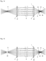
- FIG. 10 shows a further exemplary embodiment of the optical system
- FIG. 11 shows a further exemplary embodiment of the optical system
- FIG. 12 shows a further exemplary embodiment of the optical system
- FIG. 13 shows a further exemplary embodiment of the optical system
- FIG. 14 shows a further exemplary embodiment of the optical system
- FIG. 15 shows a further exemplary embodiment of the optical system
- FIG. 16 shows a further exemplary embodiment of the optical system.
- the optical system 1 according to certain embodiments of the invention comprises a camera 2 .
- the camera 2 comprises a camera optical unit 8 and a sensor 4 (or detector 4 ), wherein the camera optical unit 8 , together with the imaging optical unit 3 of the optical system 1 , images the object G onto the sensor 4 .
- the imaging optical unit 3 comprises a first partial optical unit 5 , a reflective filter element 6 and a deflection mirror 7 .
- the second partial optical unit 8 can also be part of the imaging optical unit 3 .
- the first partial optical unit 5 acts as an entrance stop or as an entrance pupil 9 with a first diameter D 1 .
- the rays of an image field of 40° pass through the entrance pupil 9 , as illustrated schematically in FIG. 1 , and then propagate divergently therefrom in the direction toward the filter element 6 .
- the filter element 6 is arranged and designed such that the rays from the image field of 40° illuminate a region with a second diameter D 2 on the filter element 6 , said second diameter corresponding to n-times the first diameter D 1 .
- n is approximately 10. Consequently, the second diameter D 2 is 10 times as large as the first diameter D 1 .
- the filter element 6 can have a curved form. In particular, it can be spherically curved for example, wherein the radius of curvature can correspond to the distance from the first partial optical unit 5 . However, the filter element 6 can also have a plane embodiment or any curved shape.
- the filter element 6 realizes pupil imaging of the entrance pupil 9 on the exit pupil 10 and, at the same time, the narrow spectral filtering.
- the conversion factor between spectral width and admissible angle range depends on the deflection angle of the rays at the filter element 6 (specifically on the cosine of half the deflection angle). If the deflection angle is 0°, an incident beam is reflected back on itself such that a desired filter width of 1 nm for radiation at 900 nm corresponds to an angle range of ⁇ 2.7°. On account of the series expansion of the cosine function, the obtainable spectral width reduces with the square of the illumination diameter ratio n.
- the filter bandwidth only reduces linearly with the illumination diameter ratio n.
- the structure as per FIG. 1 is preferred since this realizes a deflection angle of virtually 0°.
- a third diameter D 3 of the second partial optical unit 8 can correspond to the first diameter D 1 .
- An optical unit which images rays reflected by the filter element 6 can be realized in this region in particular.
- the deflection mirror 7 advantageously leads to being able to prevent an unwanted partition by the second partial optical unit 8 .
- the filter element 6 can be designed as a dichroic layer stack. In this case, it is preferable for the radius of curvature of the filter element 6 to correspond to the distance from the entrance pupil 9 such that all rays are incident into the filter structure in virtually perpendicular fashion.
- the filter element 6 can also be formed from two reflection layers/layer stacks with a transparent spacer layer, in a manner similar to a curved Fabry-Perot filter.
- a transparent equally thick spacer layer can preferably be provided as a substrate between two significantly thinner layer stacks.
- the reflective filter element 6 can particularly preferably be embodied as an optical volume hologram.
- the maximum refractive index jump of the structures in this grating should be chosen such that an effective ordinal grating number in the region of 1000 is obtained. If such volume hologram materials are used, the filter element 6 can have any curved or else plane embodiment.
- the polymer materials used for volume holograms have linear coefficients of expansion in the region of 10 ⁇ 5 /m. If the filter 6 is used in greatly varying ambient temperatures, the filter wavelength can be shifted in deterministic fashion. In this case, use should particularly preferably be made of a laser source which is adapted spectrally to the working point of the filter element 6 , for example by way of temperature control, or the measurement values should be appropriately corrected in the case of spectroscopy applications.
- an additional optically imaging element is arranged in the entrance pupil 9 or upstream or downstream of the entrance pupil 9 (such as a lens or an imaging mirror, for example), a real intermediate image can be imaged onto the filter element 6 or into the vicinity of the filter element 6 .
- the vicinity of the filter element 6 is understood to mean that the distance of the imaged real intermediate image to the filter element 6 is less than the distance to the entrance pupil 9 .
- the curvature of the filter element 6 is adapted to the field curvature of the first partial optical unit 5 and the second partial optical unit 8 .
- the filter element 6 Downstream of its filter layer, the filter element 6 can comprise a refractive index-adapted layer made of a strongly absorbent material in order to absorb transmission light and scattered light which passes through the filter 6 and hence suppress this from detection by the sensor 4 .
- the second partial optical unit 8 can be embodied as a camera lens according to the prior art.
- the second partial optical unit 8 is optimized in such a way that it realizes an image field that is as sharp and flat as possible together with the imaging performance of the filter element 6 and the optional first partial optical unit 5 .
- hybrid or diffractive optical units are also suitable for the first and/or second partial optical unit 5 , 8 .
- FIG. 2 shows an exemplary embodiment without a first partial optical unit 5 in the entrance pupil 9 .
- the second partial optical unit 8 is plotted schematically.
- the optical system 1 facilitates a large image field with a large aperture/luminous intensity, but a very narrowband detection and hence good ambient light suppression is nevertheless obtained as a result of the arrangement of the filter element 6 .
- a disadvantage of the embodiment as per FIG. 2 are the imaging aberrations as a result of the imaging effect of the filter element 6 , which realizes pupil imaging.
- the exemplary embodiment as per FIG. 2 is a design which is very simple to realize but which may have limits in terms of image sharpness.
- FIG. 3 A development of the exemplary embodiment of FIG. 2 with improved image performance is illustrated in FIG. 3 .
- the first partial optical unit 5 is formed as an asphere and a third partial optical unit 11 (which is likewise a part of the imaging optical unit 3 ) is additionally arranged between the first partial optical unit 5 and the filter element 6 , said third partial optical unit ensuring that an intermediate image is imaged on the filter element 6 .
- the third partial optical unit 11 can be formed as a planoconvex lens 11 .
- the third partial optical unit 11 can prevent imaging aberrations caused by the imaging filter element 6 .
- FIG. 3 A development of the exemplary embodiment of FIG. 2 with improved image performance is illustrated in FIG. 3 .
- the first partial optical unit 5 is formed as an asphere and a third partial optical unit 11 (which is likewise a part of the imaging optical unit 3 ) is additionally arranged between the first partial optical unit 5 and the filter element 6 , said third partial optical unit ensuring that an intermediate image is imaged on the filter element 6
- the planoconvex lens 11 is arranged symmetrically in the outward path to the filter element 6 and symmetrically in the return path from the filter element 6 .
- This realizes a comparatively simple optical arrangement made of a weakly aspherical lens 5 in the entrance pupil 9 and a second lens 11 (planoconvex lens 11 ), by means of which a diffraction-limited performance can be realized, for example for pupil dimensions in the region of 20 mm and field angles of 40°.
- the imaging filter element 6 is used in retroreflection, the division between entrance pupil 9 and exit pupil 10 can be realized by way of a pupil split.
- Two deflection mirrors 12 and 13 are provided to this end.
- a polarization split can be carried out, as illustrated in FIG. 4 .
- the desired polarization split is realized by the polarization splitter cube 14 and the downstream quarter-wave plate 15 .
- an intensity split it is also possible to implement an intensity split.
- an appropriate beam splitter cube is provided in place of the polarization splitter cube 14 .
- the quarter-wave plate 15 may be dispensed with.
- the exit pupil 10 is imaged exactly on the entrance pupil 9 in order to optimize the image quality.
- the split can also be realized by a splitter plate instead of a splitter cube.
- a polarization or intensity split is preferred since this can be implemented not only in the pupil but also on the path between entrance pupil 9 and filter element 6 , as is the case, for example, in the exemplary embodiments as per FIGS. 10 to 13 yet to be described below.
- the filter element 6 may be design as a plane component.
- a desired field plane planarization for example, can be realized by way of an additional field lens 16 (which is likewise part of the imaging optical unit 3 ), as shown schematically in FIG. 5 .
- the exemplary embodiment as per FIG. 5 is a development of the exemplary embodiment as per FIG. 3 .
- the aspherical lens 5 , the planoconvex lens 11 and the field lens 16 can be replaced by an appropriately designed diffractive optical lens 17 , which carries out the desired field planarization.
- this may be advantageous especially if the structure should be used in applications where installation space is very critical.
- this could be smartphones, for example, the overall thickness of which should be no greater than for example 7 mm.
- the image field on the filter element 6 can be folded by additional mirror elements 18 , 19 , as illustrated schematically in FIG. 6 .
- a plurality of grating arrangements for different reflecting image field components can be exposed in nested fashion in a volume hologram in this case.
- a polarization splitter cube 14 is used in this case.
- FIG. 7 shows a modification of the optical system 1 as per FIG. 6 in which the diffractive optical lens 17 is no longer provided, as a result of which no intermediate image is generated on the filter element 6 anymore.
- the mixing rod formed by the two mirror elements 18 , 19 is arranged off center in the same way as in the exemplary embodiment as per FIG. 6 , as a result of which the symmetry is broken, and ghost images caused by the filter element 6 can be prevented.
- the optical system 1 can also be realized as a narrowband source filter, as illustrated schematically in FIGS. 8 and 9 .
- eight sources Q 1 -Q 8 are arranged in exemplary fashion in an entrance pupil 9 that surrounds the exit pupil 10 .
- the light from these sources Q 1 -Q 8 is reflected in filtered fashion by the reflective filter element 6 and imaged into the exit pupil 10 .
- the illustrated sources Q 1 -Q 8 can be real sources, such as LEDs for example, or else images of such sources.
- the spatial arrangement of entrance and exit pupil 9 , 10 illustrated in FIGS. 8 and 9 should be understood to be purely exemplary.
- the entrance pupil 9 need not surround the exit pupil 10 but can be arranged next to the exit pupil 10 , for example. What is essential is that a very narrowband illumination with light passing through the exit pupil 10 is rendered possible in this way.
- the individual sources Q 1 -Q 8 can be turned on and off in succession or in selective fashion (i.e., not only be spectrally filtered in narrowband fashion but also be mirrored together in a technically simple manner).
- the optical system 1 can also be designed as a spectrometer.
- the Bragg planes in the grating extend on spherical surfaces that are perpendicular to the incident chief rays.
- the filter element work for wavelengths in the near infrared (e.g., 900 nm)
- holographic materials as are available from, e.g., Akonia Holographics or Covestro, can only be written in the visible spectral range. With these writing wavelengths of, e.g., 500 nm it is difficult to write spherical Bragg planes with a spacing of 450 nm/n 1 .
- auxiliary hologram can particularly preferably also be configured as a volume hologram, it is also possible to write a plurality of volume gratings with a different Bragg plane density to each point, as a result of which the reflective filter element 6 can be realized as a multiband filter.
- each second pixel can detect the sum from each 1 nm range above and below the absorption band and the second pixel can detect a 2 nm range on the absorption line.
- the difference signal from these two pixels then represents a level of absorption on the spectral line from which the background absorption has been removed.
- the materials from Covestro are suitable for all applications in spectral regions where they are transparent, for example from 400 to 2000 nm.
- index-modulable glasses promise greater temperature stability, and chemical and mechanical stability.
- the maximum refractive index differences that can be induced in these glasses currently still are smaller than for the polymer materials.
- writable glasses are an option for realizing the reflective filter element 6 .
- FTIR spectrometers can also be realized by the illustrated teaching according to the invention. If the volume grating is considered locally, the incident light source is reflected back at the Bragg structures. Each Bragg plane generates a back-reflected field strength component with a certain phase angle. The full field strength vector reflected back at one point of the filter element 6 emerges as the integral of the back-scattered field strength vectors with their relative phase angles over all depths of the filter element 6 . The spectral distribution of the back-scattered light components then emerges as Fourier transform of the refractive index distribution over the various depths of the filter element. If the refractive index has a sinusoidal modulation over the depth, exactly one wavelength is reflected back. The number of modulation periods or the mathematical window function of the overall thickness of the filter element 6 then determines the frequency bandwidth of the back-scattered radiation.
- the filter element 6 is designed as a double reflector with a partly reflective curved element 30 and a stepped mirror 31 arranged at a distance therefrom, with the illustration of the elements 30 and 31 in FIG. 10 being very exaggerated and not true to scale so as to be able to represent the stepped mirror 31 .
- a beam splitter plate 32 for an intensity or polarization split is provided on the path between the entrance pupil 9 and the filter element 6 .
- the second partial optical unit 8 has three lenses 33 , 34 and 35 and the exit pupil 10 is located between the lenses 34 and 35 in the exemplary embodiment shown in FIG. 10 .
- the first partial optical unit 5 is arranged in the entrance pupil 9 in order to generate an intermediate image on the filter element 6 .
- the first partial optical unit 5 can also be dispensed with if the generation of the intermediate image on the filter element 6 is not desired.
- the basic design as per FIG. 10 can be varied, for example by additional lenses upstream and/or downstream of the entrance pupil 9 (the first partial optical unit 5 can for example be dispensed with in this case), in order either to generate an intermediate image on the filter element 6 , if a spatially resolved and spectrally resolved arrangement is sought after, or to homogenize the object field.
- the two elements 30 and 31 can be arranged in two different arms as illustrated schematically in FIGS. 12 and 13 .
- the retardation path can be defined individually for each detector pixel.
- the pupil imaging of the filter element 6 must be maintained in undisturbed fashion.
- the two reflecting planes can be arranged with a slight tilt relative to one another, thus varying the retardation path linearly over the image field.
- the two faces have a spherically curved shape with a center of curvature in the center of the pupil. If both reflecting faces are realized in stepped fashion, the macroscopic arching of the filter element can be better adapted to the field curvature of the subsequent optical unit.
- each camera pixel sees approximately two-beam interference with a specific retardation path.
- the spectrometer needs to be scanned over the object in the second direction in order also to achieve the spatial resolution (and the latter in spectrally resolved fashion) also in the second direction.
- this can be achieved by an additional mechanical scanning device (not illustrated).
- the scan can be realized by the airborne motion of the spectrometer.
- a solar reference spectrum can be recorded simultaneously at the image edge by way of a white diffusing plate 36 (see FIG. 11 ).
- the back-scattering characteristic of the filter element 6 shown in FIGS. 10 and 11 does not exactly correspond to a two-beam interference but rather to a multi-beam interference of a Fabry-Perot interferometer with a very low quality factor. However, this characteristic can be taken into account and compensated for during the evaluation.
- the front element 30 e.g., a meniscus lens 30
- which is partly mirrored on the back side also has a front-side reflection which influences the overall spectral characteristic.
- the meniscus lens 30 is significantly thicker than the maximum gap width to the second stepped element 31 (or to the stepped mirror 31 ), the very fast spectral modulations caused thereby cannot be resolved and therefore be corrected by offset subtraction.
- the beam splitter plate 32 which can implement an intensity split or a polarization split, is utilized such that two split interferometer arms 25 , 26 are generated.
- a spherical mirror 27 is arranged in the first interferometer arm 25 .
- the stepped mirror 31 (illustrated schematically) is provided in the second interferometer arm 26 .
- the spherical mirror 27 and the stepped mirror 31 form the filter element 6 .
- the arms 25 , 26 can also be arranged in interchanged fashion. Further, it is possible for both elements 27 and 31 to be embodied as a stepped mirror in each case.
- the stepped mirror or the stepped element 31 is preferably mirrored over the whole front side so that it can be manufactured from any desired materials such as metals, plastics or glass. The same applies to the spherical mirror 27 .
- a polarizing beam splitter and an optical retarder plate with a retardation of ⁇ /4 are required for the realization of a polarization split.
- Such an intensity split with mirrored-apart arms as illustrated in FIG. 12 then has the advantage of double efficiency and a more easily evaluable undisturbed two-beam interference.
- the usable spectral range can be extended from the UV range (ultraviolet range) to the MIR (mid-infrared) in the case of a suitable choice of the optical materials of the remaining components.
- FTIR very sensitive spectrometer principle
- the structure as per FIG. 13 is preferred.
- the structure as per FIG. 13 is optimized for the use of two-dimensionally spatially resolving sensors with a restricted pixel resolution.
- the light incident from the surroundings can be homogenized at least over the angle spectrum by way of an illumination by means of a lens 5 (upstream of the entrance pupil 9 in the object space in this case) that has been as it were rendered to be Kohler-type, and which virtually acts as what is known as a “Kohler lens”, as shown in FIG. 13 .
- any other type of homogenization by means of an optical unit for example by means of a double lens array (e.g., in the field and aperture) (not illustrated), is also possible. These types of homogenization are known to a person skilled in the art.
- the schematically illustrated stepped mirror 31 is stepped in the direction from top to bottom in the illustration and is tilted in the direction perpendicular to the plane of the drawing such that a wedge-shaped air gap arises in this direction.
- the wedge properties are preferably set such that the gap width on the image field edge approximately corresponds to the step height in the second direction such that the path length difference is distributed in two-dimensional fashion over the detector 4 .
- the filter element 6 was always a reflective filter element 6 . However, it is equally possible to design the filter element 6 as a transmissive filter element 6 .
- FIG. 14 An exemplary embodiment of such an optical system 1 with a transmissive filter element 6 is shown in FIG. 14 , in which case the first partial optical unit 5 with the schematically illustrated converging lenses 37 and 38 between the entrance pupil 9 and exit pupil 10 is designed such that the divergently propagating beam passing through the entrance pupil 9 is rendered parallel by the converging lens 37 and is imaged onto the filter element 6 such that a spatially resolved and spectrally resolved spectrometer arrangement can be realized.
- the beam After passing through the transmissive filter element 6 , the beam is focused and passes through the second partial optical unit 8 including the exit pupil 10 , and then strikes the detector 4 .
- the retardation path in the Fabry-Perot filter element 6 can be defined individually for each detector pixel.
- the spectrometer arrangement or the spectrometer as per FIG. 14 can therefore also be referred to as a transmissive filter variant to the spectrometer as per FIG. 10 .
- an optical homogenization element 39 can be positioned in the region of the entrance pupil 9 for example, as a result of which a purely spectrally resolving spectrometer in transmission with a transmissive filter element 6 is provided.
- FIG. 16 shows a further exemplary embodiment of the optical system 1 according to the invention, in the case of which a transmissive filter element 6 is provided.
- a transmissive filter element 6 is provided in the exemplary embodiment as per FIG. 16 .
- the transmissive filter element 6 is embodied in curved fashion here (preferably with spherical curvature) and filters in transmission.
- the transmissive filter element 6 can be realized as a metal interference filter.
- thin metal layers for example with a thickness of 1 ⁇ m or less, for example with a thickness ranging from 10 to 200 nm
- dichroic spacer layers can be provided in alternating fashion with dichroic spacer layers.
- silver layers can be used if such a transmissive filter should be provided for the visible spectral range. If gold layers are used, it is particularly preferred for the transmissive filter element 6 to be designed for the infrared range or the near infrared spectral range.
- Hybrid filters with metal interference layers may also be provided. Purely dichroically coated filter elements 6 may also be provided.
- the transmissive filter element 6 can also be designed as a volume hologram or contain at least one volume hologram layer. These can be the same as or similar to the volume hologram embodiments of the reflective filter element 6 . In particular, it is possible to provide a different curvature for the transmissive filter element 6 than a spherical curvature of the transmissive filter element 6 , which is preferably present in relation to the entrance pupil 9 and/or the exit pupil 10 .
- the transmissive filter element 6 can also have a planar embodiment.
Landscapes
- Physics & Mathematics (AREA)
- General Physics & Mathematics (AREA)
- Optics & Photonics (AREA)
- Engineering & Computer Science (AREA)
- Electromagnetism (AREA)
- Computer Networks & Wireless Communication (AREA)
- Radar, Positioning & Navigation (AREA)
- Remote Sensing (AREA)
- Spectroscopy & Molecular Physics (AREA)
- Spectrometry And Color Measurement (AREA)
- Lenses (AREA)
Abstract
Description
G(0°)cos(20°)=752 nm
specifies the position of the transmission. Hence, it is possible to attain filtering with a width of only approximately 50 nm for this angle spectrum. Therefore, the prior art specifies a maximum angle of incidence for narrowband edge or bandpass filters, which may not be exceeded during the application.
Claims (20)
Applications Claiming Priority (5)
| Application Number | Priority Date | Filing Date | Title |
|---|---|---|---|
| DE102019116514 | 2019-06-18 | ||
| DE102019116514.8 | 2019-06-18 | ||
| DE102020104036.9 | 2020-02-17 | ||
| DE102020104036.9A DE102020104036A1 (en) | 2019-06-18 | 2020-02-17 | Optical system with a filter element |
| PCT/EP2020/066480 WO2020254244A1 (en) | 2019-06-18 | 2020-06-15 | Optical system with a filter element |
Publications (2)
| Publication Number | Publication Date |
|---|---|
| US20220381961A1 US20220381961A1 (en) | 2022-12-01 |
| US12189154B2 true US12189154B2 (en) | 2025-01-07 |
Family
ID=73654256
Family Applications (1)
| Application Number | Title | Priority Date | Filing Date |
|---|---|---|---|
| US17/619,570 Active 2041-10-08 US12189154B2 (en) | 2019-06-18 | 2020-06-15 | Optical system with a filter element |
Country Status (6)
| Country | Link |
|---|---|
| US (1) | US12189154B2 (en) |
| EP (1) | EP3987327B1 (en) |
| KR (1) | KR102903313B1 (en) |
| CN (1) | CN113939750A (en) |
| DE (1) | DE102020104036A1 (en) |
| WO (1) | WO2020254244A1 (en) |
Families Citing this family (1)
| Publication number | Priority date | Publication date | Assignee | Title |
|---|---|---|---|---|
| DE102023131464A1 (en) | 2023-11-13 | 2025-05-15 | Fluidect Gmbh | Detection system and method for detecting electromagnetic emission from microparticles |
Citations (5)
| Publication number | Priority date | Publication date | Assignee | Title |
|---|---|---|---|---|
| US4184749A (en) * | 1978-06-22 | 1980-01-22 | Mcdonnell Douglas Corporation | Wide angle narrow bandpass optical filter system |
| WO2008140787A2 (en) | 2007-05-09 | 2008-11-20 | Dolby Laboratories Licensing Corporation | System for 3d image projections and viewing |
| US20100171951A1 (en) * | 2009-01-05 | 2010-07-08 | Misra Anupam Kumar | Methods and apparatus for remote raman and laser-induced breakdown spectrometry |
| US20100301218A1 (en) * | 2009-05-29 | 2010-12-02 | Raytheon Company | Systems and methods for thermal spectral generation, projection and correlation |
| US20130148195A1 (en) | 2010-05-18 | 2013-06-13 | Itres Research Limited | Compact, light-transfer system for use in image relay devices, hyperspectral imagers and spectographs |
Family Cites Families (2)
| Publication number | Priority date | Publication date | Assignee | Title |
|---|---|---|---|---|
| US6721057B1 (en) * | 1999-03-13 | 2004-04-13 | California Institute Of Technology | Spatially modulated interferometer and beam shearing device therefor |
| ITPR20060059A1 (en) * | 2006-06-28 | 2007-12-29 | Mahtechs S R L | MODULAR UNIT FOR THE MANAGEMENT OF ELECTRIC LOADS OF VARIOUS TYPE AND AMPERAGE |
-
2020
- 2020-02-17 DE DE102020104036.9A patent/DE102020104036A1/en active Pending
- 2020-06-15 KR KR1020217038719A patent/KR102903313B1/en active Active
- 2020-06-15 CN CN202080040311.4A patent/CN113939750A/en active Pending
- 2020-06-15 US US17/619,570 patent/US12189154B2/en active Active
- 2020-06-15 EP EP20733919.3A patent/EP3987327B1/en active Active
- 2020-06-15 WO PCT/EP2020/066480 patent/WO2020254244A1/en not_active Ceased
Patent Citations (5)
| Publication number | Priority date | Publication date | Assignee | Title |
|---|---|---|---|---|
| US4184749A (en) * | 1978-06-22 | 1980-01-22 | Mcdonnell Douglas Corporation | Wide angle narrow bandpass optical filter system |
| WO2008140787A2 (en) | 2007-05-09 | 2008-11-20 | Dolby Laboratories Licensing Corporation | System for 3d image projections and viewing |
| US20100171951A1 (en) * | 2009-01-05 | 2010-07-08 | Misra Anupam Kumar | Methods and apparatus for remote raman and laser-induced breakdown spectrometry |
| US20100301218A1 (en) * | 2009-05-29 | 2010-12-02 | Raytheon Company | Systems and methods for thermal spectral generation, projection and correlation |
| US20130148195A1 (en) | 2010-05-18 | 2013-06-13 | Itres Research Limited | Compact, light-transfer system for use in image relay devices, hyperspectral imagers and spectographs |
Non-Patent Citations (2)
| Title |
|---|
| International Preliminary Report on Patentability rendered by the International Bureau of WIPO for PCT/EP2020/066480, dated Dec. 21, 2021, 10 pages. |
| Pradyumna K. Swain et al.: "Curved CCDs and their application with astronomical telescopes and stereo panoramic cameras", Proc. SPIE 5301, Sensors and Camera Systems for Scientific, Industrial, and Digital Photography Applications V, Jun. 7, 2004, 22 pages. |
Also Published As
| Publication number | Publication date |
|---|---|
| US20220381961A1 (en) | 2022-12-01 |
| WO2020254244A1 (en) | 2020-12-24 |
| KR20220019681A (en) | 2022-02-17 |
| EP3987327A1 (en) | 2022-04-27 |
| DE102020104036A1 (en) | 2020-12-24 |
| EP3987327B1 (en) | 2025-08-06 |
| CN113939750A (en) | 2022-01-14 |
| KR102903313B1 (en) | 2025-12-22 |
Similar Documents
| Publication | Publication Date | Title |
|---|---|---|
| JP5635624B2 (en) | Compact interference spectrometer | |
| US5801831A (en) | Fabry-Perot spectrometer for detecting a spatially varying spectral signature of an extended source | |
| US5926283A (en) | Multi-spectral two dimensional imaging spectrometer | |
| US7483147B2 (en) | Apparatus and method for measuring thickness and profile of transparent thin film using white-light interferometer | |
| US11902494B2 (en) | System and method for glint reduction | |
| US11885928B2 (en) | Functionalized waveguide for a detector system | |
| CA2782326A1 (en) | Fabry-perot fourier transform spectrometer | |
| TWI670483B (en) | Optical interference device, phase shifter array and method for producing a spatially distributed interference light pattern | |
| JP6836321B2 (en) | Acquisition of spectral information from moving objects | |
| US20210181022A1 (en) | Fourier-transform hyperspectral imaging system | |
| US7535647B1 (en) | Beam splitters for, for instance, high efficiency spectral imagers | |
| EP4334674A1 (en) | Systems and methods to acquire three dimensional images using spectral information | |
| JP6744005B2 (en) | Spectrometer | |
| US8624187B2 (en) | Imaging detector array with optical readout | |
| US12613428B2 (en) | Functionalized waveguide for a detector system and a lighting and/or projection system | |
| US20220252452A1 (en) | Compact Computational Spectrometer Using Solid Wedged Low Finesse Etalon | |
| KR20210120002A (en) | Screen comprising a transparent base body | |
| US6721057B1 (en) | Spatially modulated interferometer and beam shearing device therefor | |
| US12189154B2 (en) | Optical system with a filter element | |
| US7167249B1 (en) | High efficiency spectral imager | |
| CN107664514A (en) | A kind of multi-frame interferometry imaging optical system | |
| CN1204382C (en) | Design of multiple grating spectrograph imaging device | |
| US20230408727A1 (en) | Folded optical paths incorporating metasurfaces | |
| Gillard et al. | Angular acceptance analysis of an infrared focal plane array with a built-in stationary Fourier transform spectrometer | |
| CN113566965A (en) | Compact type wide-spectrum polarization spectrum imaging system |
Legal Events
| Date | Code | Title | Description |
|---|---|---|---|
| FEPP | Fee payment procedure |
Free format text: ENTITY STATUS SET TO UNDISCOUNTED (ORIGINAL EVENT CODE: BIG.); ENTITY STATUS OF PATENT OWNER: LARGE ENTITY |
|
| AS | Assignment |
Owner name: CARL ZEISS JENA GMBH, GERMANY Free format text: ASSIGNMENT OF ASSIGNORS INTEREST;ASSIGNORS:BUBLITZ, DANIEL;HILLENBRAND, MATTHIAS;BURKHARDT, MATTHIAS;SIGNING DATES FROM 20211109 TO 20211201;REEL/FRAME:058426/0301 |
|
| STPP | Information on status: patent application and granting procedure in general |
Free format text: DOCKETED NEW CASE - READY FOR EXAMINATION |
|
| STPP | Information on status: patent application and granting procedure in general |
Free format text: NON FINAL ACTION MAILED |
|
| ZAAB | Notice of allowance mailed |
Free format text: ORIGINAL CODE: MN/=. |
|
| STPP | Information on status: patent application and granting procedure in general |
Free format text: AWAITING TC RESP., ISSUE FEE NOT PAID |
|
| STPP | Information on status: patent application and granting procedure in general |
Free format text: NOTICE OF ALLOWANCE MAILED -- APPLICATION RECEIVED IN OFFICE OF PUBLICATIONS |
|
| STPP | Information on status: patent application and granting procedure in general |
Free format text: PUBLICATIONS -- ISSUE FEE PAYMENT RECEIVED |
|
| STPP | Information on status: patent application and granting procedure in general |
Free format text: PUBLICATIONS -- ISSUE FEE PAYMENT VERIFIED |
|
| STCF | Information on status: patent grant |
Free format text: PATENTED CASE |