US12188857B2 - Flow cytometer having configured controller - Google Patents
Flow cytometer having configured controller Download PDFInfo
- Publication number
- US12188857B2 US12188857B2 US15/936,711 US201815936711A US12188857B2 US 12188857 B2 US12188857 B2 US 12188857B2 US 201815936711 A US201815936711 A US 201815936711A US 12188857 B2 US12188857 B2 US 12188857B2
- Authority
- US
- United States
- Prior art keywords
- measurement
- information
- flow cytometer
- light
- measurement condition
- Prior art date
- Legal status (The legal status is an assumption and is not a legal conclusion. Google has not performed a legal analysis and makes no representation as to the accuracy of the status listed.)
- Active, expires
Links
Images


Classifications
-
- G—PHYSICS
- G01—MEASURING; TESTING
- G01N—INVESTIGATING OR ANALYSING MATERIALS BY DETERMINING THEIR CHEMICAL OR PHYSICAL PROPERTIES
- G01N15/00—Investigating characteristics of particles; Investigating permeability, pore-volume or surface-area of porous materials
- G01N15/10—Investigating individual particles
- G01N15/14—Optical investigation techniques, e.g. flow cytometry
- G01N15/1425—Optical investigation techniques, e.g. flow cytometry using an analyser being characterised by its control arrangement
-
- G—PHYSICS
- G01—MEASURING; TESTING
- G01N—INVESTIGATING OR ANALYSING MATERIALS BY DETERMINING THEIR CHEMICAL OR PHYSICAL PROPERTIES
- G01N15/00—Investigating characteristics of particles; Investigating permeability, pore-volume or surface-area of porous materials
- G01N15/10—Investigating individual particles
- G01N15/14—Optical investigation techniques, e.g. flow cytometry
- G01N15/1404—Handling flow, e.g. hydrodynamic focusing
-
- G—PHYSICS
- G01—MEASURING; TESTING
- G01N—INVESTIGATING OR ANALYSING MATERIALS BY DETERMINING THEIR CHEMICAL OR PHYSICAL PROPERTIES
- G01N15/00—Investigating characteristics of particles; Investigating permeability, pore-volume or surface-area of porous materials
- G01N15/10—Investigating individual particles
- G01N15/14—Optical investigation techniques, e.g. flow cytometry
- G01N15/1434—Optical arrangements
- G01N15/1436—Optical arrangements the optical arrangement forming an integrated apparatus with the sample container, e.g. a flow cell
-
- G—PHYSICS
- G01—MEASURING; TESTING
- G01N—INVESTIGATING OR ANALYSING MATERIALS BY DETERMINING THEIR CHEMICAL OR PHYSICAL PROPERTIES
- G01N35/00—Automatic analysis not limited to methods or materials provided for in any single one of groups G01N1/00 - G01N33/00; Handling materials therefor
- G01N35/00584—Control arrangements for automatic analysers
- G01N35/00722—Communications; Identification
- G01N35/00871—Communications between instruments or with remote terminals
-
- G—PHYSICS
- G01—MEASURING; TESTING
- G01N—INVESTIGATING OR ANALYSING MATERIALS BY DETERMINING THEIR CHEMICAL OR PHYSICAL PROPERTIES
- G01N35/00—Automatic analysis not limited to methods or materials provided for in any single one of groups G01N1/00 - G01N33/00; Handling materials therefor
- G01N35/00584—Control arrangements for automatic analysers
- G01N35/00722—Communications; Identification
- G01N2035/00891—Displaying information to the operator
Definitions
- the present invention relates to a flow cytometer and a particle detection method, and specifically relates to a flow cytometer and a particle detection method that easily set measurement conditions.
- Flow cytometry uses a flow cytometer capable of individually detecting individual particles by the sheath flow method, optically detects the size, structure, fluorescence intensity and the like of individual particles dispersed in the liquid, and measures the number and distribution of particles based on the detected information.
- flow cytometers there are general-purpose flow cytometers having a broad application range in which parameters such as measurement conditions of particles can be set according to user's needs, and a dedicated flow cytometers dedicated to the detection of specific particle types (for example, refer to Japanese Patent Application Publication No. 2003-287491).
- Flow cytometry can be combined with fluorescent immunostaining to detect various antigens present on the cell surface and intracellularly, and is particularly useful in cell analysis.
- one type of fluorescent dye was used, and one kind of antigen had to be detected. That is, when multiple types of antigens are present on the cell surface, the number of assays had to be increased according to the number of antigens to be detected, and the number of cells to be sampled for measurement had to be increased according to the number of assays.
- multicolor flow cytometry is problematic in that setting of the conditions necessary for measurement include a stage of immunostaining the cells and is remarkably complicated.
- the number of antigens that can be analyzed at one time has increased in conjunction with the multicolorization of fluorescent dyes, it is necessary to adjust the sensitivity of the flow cytometer for each excitation laser light source for each fluorescent dye so that each fluorescent dye can be detected most accurately in order to simultaneously detect a plurality of fluorescent dyes.
- one fluorescent dye may interfere with or amplify the fluorescence intensity of another fluorescent dye, such that it is necessary to know the compatibility of the fluorescent dye to be combined.
- Flow cytometry is a technology which greatly contributes to the diagnosis of disease, the determination of the stage of disease, and the determination of therapeutic course.
- the CD4/CD8 ratio of T lymphocytes is an examination item that was measured using free cytometry from the initial development of flow cytometry, and the ratio of CD4/CD8 was originally used as an indicator to evaluate the immune system of patients infected with human immunodeficiency virus (HIV).
- HAV human immunodeficiency virus
- the CD4/CD8 ratio also is used for the diagnosis of acute diseases such as acute organ transplant rejection and acute graft-versus-host disease.
- flow cytometry was used for diagnosing diseases that follow a chronic course, but now is very useful for diagnosis of acute phase disease. In order to diagnose acute disease, it is also necessary to respond to sudden changes in the patient's condition.
- flow cytometry is often outsourced in general hospitals since current flow cytometers have complex set-ups of measurement conditions that can only handled by trained technicians. For this reason, flow cytometry cannot be performed with a required timing such as when an examination is urgently needed in a hospital where there is no technician, and as a result, there is concern of delay in coping with the patient.
- the flow cytometer of the invention includes an input unit that receives an input of information for specifying a measurement item, a condition selection unit for selecting a measurement condition from among one or a plurality of measurement conditions corresponding to information for specifying the measurement item received by the input unit, and a measurement unit having a flow cell through which a particle-containing liquid containing particles in the sample passes, wherein the measurement unit optically measures particles of the particle-containing liquid flowing through the flow cell in accordance with the measurement condition selected by the condition selection unit.
- FIG. 1 A is a brief diagram showing the connection between a flow cytometer and an external server
- FIG. 1 B is an external view of a flow cytometer
- FIG. 2 is a brief diagram showing an optical system of a flow cytometer
- FIG. 3 is a block diagram showing an information processing system of a flow cytometer
- FIG. 4 is a diagram showing an example of information included in measurement conditions;
- FSC indicates forward scattered light
- SSC indicates side scattered light
- FL 1 , FL 2 , FL 3 , and FL 4 indicate four types of fluorescence with different peak wavelengths
- ch indicates a channel
- FIG. 5 is a function block diagram of a signal processing unit
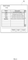
- FIG. 6 shows a screen showing a measurement condition candidate list
- FIG. 7 is a diagram showing a screen for creating a new measurement condition
- FIG. 8 is a diagram showing a sensitivity input screen
- FIG. 9 is a diagram showing a fluorescence correction value input screen
- FIG. 10 is a diagram showing a gating input screen
- FIG. 11 is a view of a measurement instruction screen
- FIG. 12 is a view of a screen showing a list of measurement conditions
- FIG. 13 is a flowchart illustrating the operation of the signal processing unit
- FIG. 14 is a flowchart illustrating an operation of a user inputting measurement conditions
- FIG. 15 is a cross-sectional view of a flow cell.
- the flow cytometer is installed in, for example, a hospital, a laboratory or the like, and is connected to the external server 11 via a network 12 such as the Internet as shown in FIG. 1 A .
- a network 12 such as the Internet as shown in FIG. 1 A .
- the network 12 is a communication medium such as the Internet, a virtual private network (VPN), a wide area communication network (WAN), a public switched telephone network (PSTN) or the like, and is not limited insofar as communication between the external server 11 and the flow cytometer 10 is possible.
- VPN virtual private network
- WAN wide area communication network
- PSTN public switched telephone network
- the external server 11 is installed in a database center or the like and has a storage device for storing the database D.
- the database D includes measurement conditions corresponding to information for specifying measurement items of the flow cytometer 10 .
- the flow cytometer 10 receives the measurement condition from the external server 11 via the network 12 .
- the database D of the external server 11 is configured to accept changes and additions of measurement conditions at any time from the server administrator.
- a general-purpose flow cytometer such as the flow cytometer 10
- the measurement item is one or more items measured by the flow cytometer 10 , and is, for example, the type of the particle, the kind of the substance present in the particle and the like. Specifically, the type of cell, type of protein, kind of sugar chain, kind of lipid, type of glycoprotein, type of glycolipid, kind of lipoprotein, kind of nucleic acid, kind of biological component such as cylinder and the like can be mentioned.
- the information for specifying the measurement item is not limited insofar as the measurement item can be specified.
- the measurement item may be the name of the measurement item itself, or the type of stain which stains the particle, the substrate of the enzyme, information on the reagent necessary for detecting particles such as antibodies, or the name of the antigen.
- the information for specifying the measurement item also includes identification information of the reagent mixed with the particles in order to measure the measurement item.
- the number of flow cytometers 10 connected to the external server 11 is not limited, and a single flow cytometer 10 also may be connected to the external server 11 .
- the flow cytometer 10 includes a flow cytometer main body 13 , and an information processing device 14 connected to the flow cytometer main body 13 .
- the flow cytometer main body 13 is provided with a suction unit 710 configured to be able to move up and down and move horizontally.
- the user positions the sample container containing a manually prepared measurement sample at the position 21 outside the flow cytometer main body 13 to measure the measurement sample in the sample container.
- the suction unit 710 moves just above the position 21 and the measurement sample is suctioned from the sample container positioned at the position 21 .
- FIG. 2 is a brief diagram showing the optical system of the flow cytometer 10 according to one embodiment.
- the flow cytometer 10 includes a flow cell 20 through which a particle-containing liquid containing particles in a sample passes, light sources 101 and 124 for irradiating light on particles passing through the flow cell 20 , and light receiving elements 100 A to 100 F for optically detecting optical information on light derived from the particles and outputting a detection signal converted into an electric signal.
- the sample is a suspension of particles suctioned by the flow cytometer.
- the particles may be artificial particles such as magnetic beads or plastic beads.
- the particles also may be biological components such as cylinders, and also may be microorganisms, animal cells, plant cells and the like.
- the particles emit one or more lights when irradiated with predetermined light.
- Light emitted from particles when irradiated with predetermined light is collectively referred to as light derived from particles.
- Light derived from the particles includes scattered light and luminescence.
- the light derived from the particles may be light of any wavelength, but preferably is light having a peak wavelength in the range of 400 nm to 850 nm. More specifically, the light derived from the particles is preferably fluorescence.
- the light derived from the particles also may be light emitted by a substance contained in the particles themselves.
- light derived from the particles may be labeled with a luminescent substance such as a fluorescent substance, and light emitted from the luminescent substance may be detected as light derived from the particles.
- the peak wavelength of light derived from particles is preferably different for each measurement item.
- the particle-containing liquid is a liquid containing the particle suspension liquid suctioned from the sample into the flow cytometer, and includes a diluting liquid as necessary.
- the optical information is information included in one or two or more light wavelength spectra emitted from particles.
- the light wavelength spectra include the individual light wavelengths and light wavelength regions included in a light wavelength spectrum and the respective light wavelengths or the intensities of the light wavelength regions.
- Individual light wavelengths and wavelength ranges can be specified by which one of the one or more light receiving elements described later has received light.
- Each light wavelength or intensity of each light wavelength region can be specified by an electric signal output from the light receiving elements 100 A to 100 F which have received light.
- the light emitted from the light source 101 irradiates the flow cell 20 via the collimator lens 102 , the dichroic mirror 103 , and the condenser lens 104 .
- the forward scattered light of the light derived from the particles passing through the flow cell 20 is collected by the condenser lens 105 and enters the light receiving element 100 A via the beam stopper 106 , the pinhole plate 107 , and the band pass filter 108 .
- side scattered light and lateral fluorescence derived from the particles passing through the flow cell 20 are collected by the condenser lens 109 .
- the side scattered light enters the light receiving element 100 B via the dichroic mirrors 110 , 111 , 112 , the pinhole plate 103 , and the band pass filter 114 .
- the lateral fluorescence having a wavelength of 520 nm or more and 542 nm or less passes through the dichroic mirrors 110 and 111 , is reflected by the dichroic mirror 112 , and enters the light receiving element 100 C via the pinhole plate 115 and the band pass filter 116 .
- the lateral fluorescence having a wavelength of 570 nm or more and 620 nm or less passes through the dichroic mirror 110 , is reflected by the dichroic mirror 111 , and enters the light receiving element 100 D via the pinhole plate 117 and the bandpass filter 118 .
- the lateral fluorescence having a wavelength of 670 nm or more and 800 nm or less also is reflected by the dichroic mirror 110 , passes through the dichroic mirror 119 , and enters the light receiving element 100 E via the pinhole plate 120 and the bandpass filter 121 .
- the light emitted from the light source 124 irradiates the flow cell 20 via the collimator lens 125 , the dichroic mirror 103 , and the condenser lens 104 .
- the lateral fluorescence of the light derived from the particles passing through the flow cell 20 is collected by the condenser lens 109 .
- the lateral fluorescent light of 662.5 nm or more and 687.5 nm or less is reflected by the dichroic mirror 110 , reflected by the dichroic mirror 119 , then enters the light receiving element 100 F via the pin hole plate 122 and the band pass filter 123 .
- a laser diode with a wavelength of 488 nm is used for the light source 101
- a laser diode with a wavelength of 642 nm is used for the light source 124
- a sheath flow cell is used for the flow cell 20 .
- a photodiode also is used for the light receiving element 100 A for receiving the forward scattered light
- an avalanche photodiode (APD) is used for the light receiving element 100 B for receiving the side scattered light
- photomultiplier tubes Photo Multiplier Tube, PMT are used for light receiving elements 100 C to 100 F.
- the flow cytometer 10 includes six light receiving elements 100 A to 100 B, and the four light receiving elements 100 C to 100 F are for respectively detecting optical information of the four lights having different peak wavelengths derived from a stain bonded to particles in a sample, but the invention is not limited to this and it is also possible to provide three or more light receiving elements and at least two or more of the three or more light receiving elements may detect optical information of light originating from at least two stains having different peak wavelengths.
- each fluorescence can be detected by the four light receiving elements 100 C to 100 F.
- the number of light sources may be one, or two or more.
- the light source is selected according to the wavelength region of light derived from the stain bound to the particle. When the light sources are 2 or more, it is preferable that these light sources emit light having different peak wavelengths. Two light sources or more are preferable because it is possible to separate and detect fluorescence with high accuracy as compared with the case where there is only one light source. For example, when one light source is used in HIV testing, FITC is used as a labeled antibody dye for CD4 and PEcy5 is used as a labeled antibody dye for CD8; however, the peak wavelength of fluorescence from FITC and fluorescence from PEcy 5 are close to each other and the overlapping portions of the respective wavelength regions tend to be large.
- the number of photodiodes, dichroic mirrors, and bandpass filters can be varied according to the number of peak wavelengths of light derived from the particles.
- the types of photodiodes, dichroic mirrors, and bandpass filters can also be selected according to the peak wavelength of light derived from the particle, the wavelength region, and the intensity thereof.
- the detection signals output from the light receiving elements 100 A to 100 F are amplified by the amplifying sections 130 A to 130 F, subjected to A/D conversion by the A/D conversion units 131 A to 131 F, and input to the signal processing unit 63 .
- the amplifying units 130 A and 130 B connected to the light receiving element 100 A which is a photodiode and the light receiving element 100 B which is an APD are known amplifying circuits configured by operational amplifiers or the like, and the output voltages of the light receiving elements 100 A and 100 B to be input are adjusted by adjusting the amplification degree of each amplifier circuit.
- the output voltage of the PMT is adjusted by adjusting the voltage value applied to the light receiving elements 100 C to 100 F which are PMTs.
- the adjustment of the detection sensitivity of the light receiving elements 100 A to 100 F refers to adjustment of the degree of amplification of the amplifying circuit in the light receiving elements 100 A and 100 B, and the adjustment of the voltage applied to the light receiving elements 100 C to 100 F in the light receiving circuits 100 C to 100 F.
- the detection signal output from the light receiving element is amplified by adjusting the amplification degree in the amplification circuit in the light receiving elements 100 A and 100 B, and the detection signal output by the light receiving elements 100 C to 100 F is adjusted by adjusting the voltage applied to the light receiving elements 100 C to 100 F.
- amplification includes the case where the ratio of the output signal to the input signal is 1 or more and the case where the ratio is less than 1.
- Known amplification circuits also may be included in the amplifying units 130 C to 130 F connected to the light receiving elements 100 C to 100 F, and adjustment of the detection sensitivity of the light receiving elements 100 C to 100 F also may include adjusting the output voltages of the light receiving elements 100 C to 100 F via the amplification circuits.
- the flow cytometer 10 is provided with the structure of FIG. 2 that includes a light source 124 , the flow cell 20 , and the light receiving elements 100 A to 100 F, the amplifying sections 130 A to 130 F, and a measurement unit 65 that includes the A/D conversion units 131 A to 131 F, the signal processing unit 63 , and a temperature sensor 22 to be described later.
- the measurement unit 65 optically measures the particles in the particle-containing liquid passing through the flow cell 20 according to the measurement condition received by the communication unit 64 described later.
- measurement includes detecting optical information of light derived from the particles by the light receiving elements 100 A to 100 F and storing the detection signals output by the light receiving elements 100 A to 100 F, and also includes processes performed by the signal processing unit 63 (to be described later) such as, for example, generating the particle count result and the like using the stored detection signals.
- the detection signals output from the light receiving elements 100 A to 100 F include signals output from the A/D conversion units 131 A to 131 F via the amplifiers 130 A to 130 F.
- the flow cytometer 10 includes a flow cytometer main body 13 and an information processing apparatus 14 connected to the flow cytometer main body 13 , and the structure of FIG. 2 incorporating the light source 124 , flow cell 20 , and light receiving elements 100 A to 100 F of the measurement unit 65 , as well as the amplification units 130 A to 130 F, and the A/D conversion units 131 A to 131 F are arranged in the flow cytometer main body 13 .
- the signal processing unit 63 also is arranged in the information processing apparatus 14 . Note that, when the flow cytometer 10 does not include the information processing device 14 , the signal processing unit 63 may be disposed in the flow cytometer main body 13 .
- the flow cytometer 10 also has a control unit for controlling a pump, a motor and the like (not shown) in order to perform measurements by passing the particle-containing liquid through the flow cell 20 , although the signal processing unit 63 may also serve as this control unit, or this control unit may be separately arranged in the information processing apparatus 14 or the flow cytometer main body 13 .
- the flow cytometer 10 receives the measurement condition from the external server 11 in order to set the measurement condition according to the measurement item prior to the measurement.
- FIG. 4 shows an example of information included in the received measurement condition in the case where the light derived from the particle is fluorescent.
- the measurement condition includes basic information relating to measurement (hereinafter referred to as “basic measurement information”), information relating to adjustment of detection sensitivity for detecting optical information (hereinafter referred to as “information relating to adjustment of detection sensitivity”), information relating to correction of the detected optical information, information related to gating for setting an area of the particles to be selected based on the optical information (hereinafter referred to as “information related to gating”), and a calculation formula for use in temperature correction described later.
- basic measurement information information relating to measurement
- information relating to adjustment of detection sensitivity information relating to adjustment of detection sensitivity
- information relating to correction of the detected optical information information related to gating for setting an area of the particles to be selected based on the optical information
- the basic measurement information includes basic information, measurement information, and a threshold value.
- the basic information includes identification information (referred to as “measurement condition ID” in FIG. 4 ) for identifying the type of measurement condition and a measurement condition name.
- the measurement information includes the analytical capacity of the sample suctioned into the flow cytometer, the flow rate indicating the flow speed when the particles flow into the flow cytometer, and the dilution ratio of the sample suctioned into the flow cytometer.
- the threshold value is also called a detection level and is a set value of the lower limit of the optical information detected as particles.
- the threshold value is set for each light receiving element 100 A to 100 F with respect to light originating from the particle. For example, the threshold value can be set within a numerical value range of 0 to 1023 according to the intensity of light. If the threshold value is set at 50, light having a light intensity of 50 or more is detected as a particle.
- Information relating to adjustment of the detection sensitivity includes at least one of a value indicating the amplification degree of the output voltage of the light receiving elements 100 A to 100 F, and a voltage value applied to the light receiving elements 100 A to 100 F.
- a value indicating the amplification degree of the output voltage of the light receiving elements 100 A to 100 F For example, an amplification value for adjusting the amplification degree of the amplification circuit connected to the light receiving elements 100 A and 100 B and a PMT voltage value for adjusting the voltage applied to the light receiving elements 100 C to 100 F.
- the information may include only one of the amplification value and the PMT voltage value.
- the information may include an amplification value for adjusting the amplification degree in the amplifying circuit.
- the information related to the correction of the detected optical information includes information on the light wavelength distribution amount outside the detection target included in the optical information detected by the light receiving elements 100 A to 100 F. This is because when two or more lights with different peak wavelengths emitted by particles are detected in one measurement, the wavelength regions of the two or more lights may partially overlap one another. Therefore, the light which is not the detection target leaks into the light to be detected, and the specificity of detection of light may decrease.
- the distribution of the wavelength of the light and the amount of light are referred to as the light wavelength distribution amount, and the distribution of the wavelength of the leaked light and its amount are referred to as the non-detection target light wavelength distribution amount.
- fluorescence correction is performed to remove the electrical signals originating from the non-detection target fluorescence, and capture only the optical information from the fluorescence to be detected from the electric signals of the light receiving elements 100 C to 100 F.
- Information relating to the light wavelength distribution amount outside the detection target included in the detected optical information is indicated as a fluorescence correction value in FIG. 4 , and is used for this fluorescence correction.
- the simplest fluorescence correction value is the light wavelength distribution amount of the fluorescence which is not to be detected that should be subtracted from the light wavelength distribution amount of the fluorescence to be detected.
- fluorescence 1 and fluorescence 2 when fluorescence having two different peak wavelengths is defined as fluorescence 1 and fluorescence 2, and if the light wavelength distribution does not overlap between fluorescence 1 and fluorescence 2 and there is no need for fluorescence correction, the fluorescence correction value of fluorescence 1 is 0.0.
- fluorescence 1 and fluorescence 2 are simultaneously measured, the light distribution wavelengths overlap; when the overlapping light wavelength distribution amount is 27.5%, the fluorescence correction value can be set to 27.5 to subtract the fluorescence distribution amount derived from fluorescence 2 is calculated from the fluorescence distribution amount of fluorescence 1.
- Information related to gating includes information related to a distribution setting on a distribution map of light derived from particles.
- a distribution diagram of light originating from particles called a scattergram or a histogram, and is created for one measurement item or for each of two or more measurement items from the detected optical information.
- the scattergram represents the distribution of light originating from the particle on the two axes of X axis and Y axis for two measurement items.
- the histogram is represented by the intensity of light and the number of its particles for one measurement item.
- Gating refers to selection of a fixed distribution region corresponding to a measurement item in a distribution map for appropriate measurement according to the measurement item relative to the respective distribution map. More specifically, gating means setting the following information.
- Information relating to the scattergram, information related to the histogram, and information related to gating is included in the distribution setting information on distribution of light derived from particles.
- the information relating to the scattergram is information for creating a scattergram, and includes the scattergram name which indicates the name of the scattergram to be created, the upper gate, X-axis channel (referred to as “X-axis channel”) indicating the photodiode receiving the light representing a first measurement item, X-axis channel name, Y-axis channel (referred to as Y-axis channel) indicating the photodiode receiving light representing a second measurement item, and Y-axis channel name.
- the information related to the histogram is information for creating a histogram, and includes a histogram name, an upper gate, an X axis channel indicating the photodiode receiving light representing the measurement item, and X-axis channel name.
- the upper gate indicates the gate of the previously created scattergram when creating respectively corresponding scattergrams using two or more gates.
- the information related to the gate is for determining the area of each particle selected from the scattergram and the histogram, and includes a gate name which is the name of the selected gate, position information indicating the position of the gate, a color given on the display unit for the received light wavelength or wavelength range, the measurement item name, the upper limit value of the intensity of the received light, the lower limit value of the intensity of the received light, and the result value type when displaying the analysis result.
- the result value types are various statistical processing values of the result, for example, the total number of particles, the average value, the variation coefficient, the ratio to the whole, the mode, and the like.
- the number of scattergrams and histograms created differs depending on measurement items. Therefore, there are cases where a plurality of scattergram related information, histogram related information, and gate related information are included in accordance with the number of scattergrams and histograms to be created.
- FIG. 3 shows the configuration of the information processing system of the flow cytometer 10 , which includes an input unit 60 , a condition input unit 61 , a display unit 62 , a signal processing unit 63 , and a communication unit 64 .
- the signal processing unit 63 acquires the detection signals output from the light receiving elements 100 A to 100 F via the amplifiers 130 A to 130 F and the A/D converters 131 A to 131 F.
- a temperature sensor 22 is provided to detect the temperature of the particle-containing liquid and output a temperature detection signal converted into an electric signal; the signal processing unit 63 acquires the temperature detection signal from the temperature sensor 22 through the temperature detection circuit 132 and the A/D conversion unit 133 .
- the input unit 60 is configured by a barcode reader and accepts input of information for specifying measurement items by reading a barcode attached to a container containing a reagent to be mixed with particles.
- the input unit 60 may be an RFID reader that reads information for specifying a measurement item from a tag attached to a container.
- the input unit 60 also may be configured by at least one of a keyboard and a mouse, and the user may manually input information for specifying measurement items or select from among a plurality of options prepared in advance.
- condition input unit 61 may be configured with at least one of a keyboard, a mouse, and a touch panel to accept input of measurement conditions when a user inputs measurement conditions.
- the display unit 62 is configured by, for example, a monitor, and displays the screens 90 to 96 shown in FIGS. 6 to 12 and the analysis result.
- the input unit 60 , the condition input unit 61 , and the display unit 62 are disposed in the information processing apparatus 14 connected to the flow cytometer main body 13 , but also may be arranged in the flow cytometer main body 13 .
- the communication unit 64 is configured by a communication device for communicating with the external server 11 via the network 12 according to a predetermined communication standard. Information for specifying measurement items is transmitted to the external server 11 via the network 12 , and measurement conditions and the like corresponding to information for specifying measurement items are received from the external server 11 via the network 12 .
- the signal processing unit 63 includes a memory 82 used as a work area for data processing, a storage unit 83 for recording programs and processing data, a CPU (Central Processing Unit) 81 for performing data processing described later, a bus 84 for relaying data between units, and interface units (I/F units in FIGS. 3 ) 85 and 86 which perform data input/output between the respective units 60 , 61 , 62 , and 64 connected to the signal processing unit 63 , or inputs detection signals output from the light receiving devices 100 A to 100 F via the amplifiers 130 A, 130 F and A/D conversion units 131 A to 131 F, or inputs a temperature detection signal from the temperature sensor 22 via the temperature detection circuit 132 and the A/D conversion unit 133 .
- the processing performed by the signal processing unit 63 actually means the processing performed by the CPU 81 of the signal processing unit 63 .
- the CPU 81 temporarily stores necessary data (such as intermediate data being processed) using the memory 82 as a work area, and records data to be stored longterm in the storage unit 83 .
- the signal processing unit 63 By executing a program stored in the storage unit 83 or the memory 82 , the signal processing unit 63 performs data processing to realize the functions of a measurement item acquisition unit 70 , a measurement condition selection unit 71 , a measurement condition storage unit 72 , a first measurement condition setting unit 73 , a temperature correction unit 74 , a data processing unit 75 , a second measurement condition setting unit 76 , and a calculation unit 77 , and controls the operation of each unit connected to the signal processing unit 63 .
- FIG. 13 is a flowchart illustrating the operation of the signal processing unit 63 and the external server 11 of the flow cytometer 10 of the invention.
- the measurement item acquisition unit 70 performs the process ST 10
- the measurement condition selection unit 71 performs process ST 11 to ST 16
- the measurement condition storage unit 72 performs processes ST 17 and ST 18
- the first measurement condition setting unit 73 and temperature correction unit 74 perform the process of ST 19
- data processing unit 75 performs the process ST 20
- the process ST 21 is performed by the calculation unit 77 .
- the processes from ST 50 to ST 54 are performed in the external server 11 . Note that the information that the signal processing unit 63 exchanges with the external server 11 is performed via the communication unit 64 .
- the signal processing unit 63 acquires information for specifying the measurement item. For example, using the barcode reader as the input unit 60 , information for specifying the measurement item is read from the barcode attached to the reagent container. The information for specifying the measurement item is, for example, the identification information of the reagent mixed with the particle. In ST 11 , the signal processing unit 63 transmits information for specifying the measurement item to the external server 11 . Note that the barcode attached to the reagent container also may include manufacturer identification information for identifying the manufacturer of the reagent.
- the measurement condition is received from the external server 11 only when manufacturer identification information indicating a specific manufacturer is acquired from the bar code of the reagent container, and a notice indicating a measurement condition is not received is displayed on the display unit 62 when the manufacturer identification information indicating a specific manufacturer is not obtained.
- the external server 11 receives information for specifying the measurement item.
- the external server 11 searches whether a measurement condition corresponding to information (identification information of the reagent) for specifying this measurement item exists in the database and, in ST 52 , the search result is transmitted to the signal processing unit 63 .
- the search result is either information on a list (hereinafter referred to as “measurement condition candidate list”) showing one or more measurement condition candidates corresponding to the information (identification information of the reagent) for specifying the measurement item, or information indicating that there is no corresponding measurement condition.
- the measurement condition candidate list includes the measurement condition name, measurement condition description and the like corresponding to the measurement items that can be measured using the reagent in the reagent container from which the identification information of the reagent was read in ST 10 .
- the identification information of the reagent containing the labeled antibody against CD4 the labeled antibody against CD45 or the like is read in ST 10
- the measurement conditions corresponding to the HIV test, the hematopoietic stem cell test and the like that can be carried out using these labeled antibodies are included in the list.
- Detection signals output from the light receiving elements 100 A to 100 F are input to the signal processing section 63 via the amplifying sections 130 A to 130 F and the A/D converting sections 131 A to 131 F.
- the signal processing unit 63 performs correction of this detection signal, that is, so-called fluorescence correction, by using the light wavelength distribution amount outside the detection target included in the detected optical information.
- the signal processing unit 63 also reads out a calculation formula used for temperature correction from the measurement conditions stored in the storage unit 83 , and uses the temperature detection signal output from the temperature sensor 22 and the calculation formula to correct the detection signals output from the light receiving elements 100 A to 100 F, which will be described later in detail.
- the signal processing unit 63 performs analyses including the measurement of the number of particles using the fluorescence correction and the temperature-corrected detection signal, and outputs the analysis result.
- the output of the analysis result is, for example, displaying the analysis result on the display unit 62 together with the distribution chart.
- the signal processing unit 63 also may store the input detection signal in the storage unit 83 without displaying the analysis and the analysis result of ST 21 , and the communication unit 64 may transmit the detection signal stored in the storage unit 83 to external server 11 or another external server other than the external server 11 , such that the analysis performed by the external server 11 or another external server other than the external server 11 can be displayed as analysis results.
- FIG. 14 is a flow chart describing the sequence of the operation of accepting input of a measurement condition by a user when the communication unit 64 does not receive a measurement condition from the external server 11 because there is no measurement condition corresponding to the information for specifying a measurement item in the external server 11 .
- the processes from ST 31 to ST 40 are performed by the second measurement condition setting unit 76 .
- the screens 91 to 95 for the user to perform the input operation of the measurement condition from the condition input unit 61 are sequentially displayed on the display unit 62 in the wizard format, and the measurement conditions input by the user are set.
- the signal processing unit 63 displays the new creation screen 91 shown in FIG. 7 on the display unit 62 .
- the signal processing unit 63 accepts the name of the measurement condition and comment and the like input by the user in the input box on the screen 91 .
- the signal processing unit 63 When the signal processing unit 63 accepts a screen switching instruction by the user pressing the “Next” button 93 a on the screen 93 , in ST 37 , the signal processing unit 63 displays on the display unit 62 a screen (hereinafter referred to as “gating input screen”) 94 for setting an area of selected particles based on the optical information, as shown in FIG. 10 . In ST 38 , the signal processing unit 63 receives information related to gating that the user input in the input box on the screen 94 .
- the signal processing unit 63 stores the value indicating degree of amplification of the output voltage of the light receiving elements 100 A and 100 B, voltage value applied to the light receiving elements 100 C to 100 F, fluorescence correction value, and information related to gating from the user as measurement conditions.
- the signal processing unit 63 accumulates measurement conditions input by the user. That is, the measurement condition input by the user is added to the measurement condition list in which the measurement conditions received in the past are accumulated, and this list is stored.
- a list of measurement conditions in which both measurement conditions input by the user and measurement conditions received from the external server 11 are both stored also may be stored, and a measurement condition list of accumulated measurement conditions input by the user and a measurement condition list of accumulated measurement conditions received from the external server 11 also may be stored.
- the user When inputting each information on the screens 92 , 93 , 94 , the user preliminarily measures a control sample consisting of artificially created components such as a single-dye control sample stained only with FITC, for example, one or more times, then, based on the measurement result, a value indicating an appropriate amplification degree, a voltage value, a fluorescence correction value, and information related to gating may be determined.
- the signal processing unit 63 Upon receiving a measurement instruction of the control sample from the user while each screen 92 , 93 , 94 is displayed, the signal processing unit 63 causes the measurement instruction screen 95 shown in FIG. 11 to be displayed on the screens 92 , 93 , and 94 .
- the signal processing unit 63 confirms that the control sample is set at the predetermined position, and starts the preliminary measurement according to the measurement instruction.
- the signal processing unit 63 performs the preliminary measurement again.
- the signal processing unit 63 redisplays the distribution diagram of the scattergram and the like on the screen 93 .
- the order of displaying the screens 92 , 93 , and 94 is not limited, and may be in any order.
- the signal processing unit 63 calls up the accumulated measurement condition list according to the user's request, and displays a screen 96 that displays the measurement condition list shown in FIG. 12 , and displays this list on the display unit 62 .
- the signal processing unit 63 sets this measurement condition in the same manner as ST 19 .
- the flow cell 20 shown in FIG. 15 includes a rectification part 23 , an acceleration part 24 , and an orifice part 25 .
- the rectification part 23 is cylindrical and has a through hole.
- the acceleration part 24 is conical, and the diameter of the hole communicating with the hole of the rectification part 23 gradually decreases toward the orifice part 25 .
- the orifice part 25 of the flow cell 20 is a transparent rectangular tube having a square cross section, and the particle-containing liquid passing through the hole is irradiated with the light L from the light sources 101 and 124 .
- the flow cell 20 is fixed to the fixture 26 , and the nozzle 21 is inserted into the flow cell 20 and attached to the fixture 26 .
- a sensor setting member 27 having a flow path 27 a is connected to an outlet of the orifice part 25 of the flow cell 20 .
- the sensor setting member 27 is provided with a temperature sensor 22 and a nipple 28 .
- the particle-containing liquid introduced into the flow path 27 a from the orifice part 25 contacts the temperature sensor 22 and is discharged from the nipple 28 .
- a thermistor (PB3M-35-TI type manufactured by Shibaura Electronics Co., Ltd.) is used as the temperature sensor 22 .
- the sheath liquid flowing in from the inflow port 26 a of the fixture 26 is rectified by the rectification part 23 , and the flow is accelerated by the acceleration part 24 .
- the sample flowing into the nozzle 21 from the direction of the arrow B is ejected from the tip of the nozzle 21 toward the orifice part 25 , the sample is enveloped by the accelerated sheath liquid, and passes through the orifice part 25 as a particle-containing liquid.
- Light L is irradiated on the particle-containing liquid, and light derived from the particles in the particle-containing liquid is detected by light receiving elements 100 A to 100 F shown in FIG. 2 .
- the liquid temperature of the particle-containing liquid that has passed through the orifice section 25 is detected by the temperature sensor 22 , and the liquid is discharged from the nipple 28 in the direction of arrow C.
- the above-described mounting position of the temperature sensor 22 is an example, and the temperature sensor 22 also may be provided, for example, at the entrance or the vicinity of the flow cell 20 as long as it is attached to a certain position, or it may be provided outside the flow cell 10 insofar as the temperature sensor 22 is attached at a position where the temperature of the particles to be detected is substantially the same as the temperature of the particle-containing liquid passing through the orifice part 25 .
- Detection signals of the light receiving elements 100 A to 100 F are input to the amplifying sections 130 A to 130 F.
- a 0.5 V constant voltage is input to the amplification unit as the low level reference voltage RL, and a control voltage is input from the signal processing unit 63 as the high level/reference voltage RH.
- a correction curve (actually measured values) of the detection signal of the light receiving elements 100 A to 100 F relative to the temperature detected by the temperature sensor 22 shows the relationship of the control voltage to the temperature (° C.).
- the measurement item is reticulocyte
- it is expressed as calculation formula (A).
- y 4.4838 (x ⁇ 23) 2 ⁇ 64.815 (x ⁇ 23)+3031 . . . (A), where x is the temperature (° C.) detected by the temperature sensor 22 , and y is the control voltage (digital value).
- the calculation formula (A) is received from the external server 11 as a measurement condition for each measurement item.
- the ratio of the output to the input of the A/D converter is determined by the difference (RH ⁇ RL) between RH and RL. Since RL is constant, the degree of amplification is controlled by RH, that is, the control voltage determined by the calculation formula (A), and the detection signals of the light receiving elements 100 A to 100 F are temperature-corrected by the detected temperature of the temperature sensor 22 .
- the temperature correction method is not limited to this method, inasmuch as, for example, the respectively voltage applied to the light receiving elements 100 A to 100 F also may be adjusted based on the temperature detection signal of the temperature sensor 22 .
- the analysis result obtained by the calculation unit 77 also may be corrected.
- an appropriate measurement condition is selected from one or a plurality of measurement conditions according to measurement items.
- a measurement condition is selected from one or a plurality of measurement conditions received from the external server 11 . Therefore, it is not necessary for the user to input complicated measurement conditions himself. Therefore, measurement conditions can be easily set even by a non-specialist technician who has not received specialized training.
- the user can set the measurement condition from the condition input unit 61 .
- the flow cytometer 10 of another embodiment includes a temperature sensor for detecting the temperature inside the flow cytometer 10 and outputting a temperature detection signal converted into an electric signal, and a temperature adjustment device for heating or cooling the interior of the flow cytometer 10 provided at an arbitrary position within the flow cytometer 10 .
- the temperature adjustment device includes, for example, at least one of a heater and a fan.
- the signal processing unit 63 does not include the temperature correction unit 74 .
- the temperature adjustment device is connected to the signal processing unit 63 , and the temperature adjustment device performs controls so that the temperature in the flow cytometer 10 becomes a target temperature using the temperature detection signal output from the temperature sensor 22 .
- the target temperature may be included in the measurement condition received from the external server 11 by the signal processing unit 63 , or may be stored in advance in the signal processing unit 63 . Since the temperature inside the flow cytometer 10 is kept constant, the signal processing unit 63 does not need to perform temperature compensation on the detection signal output from the light receiving elements 100 A to 100 F. Once the measurement condition corresponding to the information for specifying the measurement item is received and the measurement is started, there is no need for the user to change the measurement condition according to the temperature. Since other configurations are the same as those of the flow cytometer 10 shown in FIGS. 1 to 15 , description thereof is omitted.
- one or a plurality of measurement conditions corresponding to the identification information of the reagent are received from the external server 11 , and the measurement condition is selected from among them in the embodiment, one or a plurality of measurement conditions corresponding to the identification information of the reagent also may be previously stored in the storage unit 83 of the flow cytometer 10 and the measurement condition may be selected from one or more measurement conditions read out from the storage unit 83 ; and measurement conditions also may be stored in advance in a storage unit of an external computer installed in the facility of the user, for example, a host computer that manages the examination room, and the flow cytometer 10 may receive the measurement condition from the host computer.
Landscapes
- Chemical & Material Sciences (AREA)
- Biochemistry (AREA)
- Physics & Mathematics (AREA)
- Health & Medical Sciences (AREA)
- Life Sciences & Earth Sciences (AREA)
- Analytical Chemistry (AREA)
- General Health & Medical Sciences (AREA)
- General Physics & Mathematics (AREA)
- Immunology (AREA)
- Pathology (AREA)
- Dispersion Chemistry (AREA)
- Investigating, Analyzing Materials By Fluorescence Or Luminescence (AREA)
- Investigating Or Analysing Biological Materials (AREA)
Abstract
Description
Claims (18)
Priority Applications (1)
| Application Number | Priority Date | Filing Date | Title |
|---|---|---|---|
| US18/960,168 US20250085209A1 (en) | 2017-03-30 | 2024-11-26 | Flow cytometer and particle detection method |
Applications Claiming Priority (2)
| Application Number | Priority Date | Filing Date | Title |
|---|---|---|---|
| JP2017-067469 | 2017-03-30 | ||
| JP2017067469A JP7009071B2 (en) | 2017-03-30 | 2017-03-30 | Flow cytometer and particle detection method |
Related Child Applications (1)
| Application Number | Title | Priority Date | Filing Date |
|---|---|---|---|
| US18/960,168 Continuation US20250085209A1 (en) | 2017-03-30 | 2024-11-26 | Flow cytometer and particle detection method |
Publications (2)
| Publication Number | Publication Date |
|---|---|
| US20180284008A1 US20180284008A1 (en) | 2018-10-04 |
| US12188857B2 true US12188857B2 (en) | 2025-01-07 |
Family
ID=61827588
Family Applications (2)
| Application Number | Title | Priority Date | Filing Date |
|---|---|---|---|
| US15/936,711 Active 2039-11-15 US12188857B2 (en) | 2017-03-30 | 2018-03-27 | Flow cytometer having configured controller |
| US18/960,168 Pending US20250085209A1 (en) | 2017-03-30 | 2024-11-26 | Flow cytometer and particle detection method |
Family Applications After (1)
| Application Number | Title | Priority Date | Filing Date |
|---|---|---|---|
| US18/960,168 Pending US20250085209A1 (en) | 2017-03-30 | 2024-11-26 | Flow cytometer and particle detection method |
Country Status (4)
| Country | Link |
|---|---|
| US (2) | US12188857B2 (en) |
| EP (1) | EP3382373B1 (en) |
| JP (2) | JP7009071B2 (en) |
| CN (1) | CN108693100B (en) |
Families Citing this family (15)
| Publication number | Priority date | Publication date | Assignee | Title |
|---|---|---|---|---|
| JP6309896B2 (en) | 2011-12-01 | 2018-04-11 | ピー.エム.エル. − パーティクルズ モニタリング テクノロジーズ リミテッド | Detection scheme for particle size and concentration measurement |
| JP7199780B2 (en) * | 2018-09-26 | 2023-01-06 | シスメックス株式会社 | Sample analysis system and sample analysis method |
| JP7352340B2 (en) * | 2018-09-28 | 2023-09-28 | シスメックス株式会社 | Measuring device and accuracy control method |
| JP7212065B2 (en) * | 2018-12-19 | 2023-01-24 | 株式会社クボタ | Mechanical equipment diagnostic system, mechanical equipment diagnostic method, and mechanical equipment diagnostic program |
| JP2020144054A (en) * | 2019-03-07 | 2020-09-10 | 学校法人昭和大学 | Peripheral blood circulation cancer cell detection method and detection device |
| KR102142248B1 (en) * | 2019-04-12 | 2020-08-07 | (주)에이치앤지텍 | An Apparatus for Measuring a Particle of a Compressed Air |
| JP1655021S (en) * | 2019-06-21 | 2020-03-16 | cell analyzer | |
| JP2021076451A (en) * | 2019-11-07 | 2021-05-20 | ソニー株式会社 | Detection optical system, detector, flow cytometer, and imaging cytometer |
| CN114729868A (en) | 2019-11-22 | 2022-07-08 | 粒子监测系统有限公司 | Advanced system and method for interferometric particle detection and detection of particles having small size dimensions |
| JP7721908B2 (en) * | 2021-02-12 | 2025-08-13 | セイコーエプソン株式会社 | Color measurement method and color measurement system |
| JP7721289B2 (en) * | 2021-03-12 | 2025-08-12 | シスメックス株式会社 | Analysis method and analysis device |
| EP4060319A1 (en) | 2021-03-12 | 2022-09-21 | Sysmex Corporation | Analysis method and analyzer |
| JP7764140B2 (en) * | 2021-05-06 | 2025-11-05 | 株式会社ディスコ | processing equipment |
| CN114720681A (en) * | 2022-05-11 | 2022-07-08 | 深圳市帝迈生物技术有限公司 | Sample analyzer and multi-joint-inspection filtering method thereof |
| JP2024047826A (en) * | 2022-09-27 | 2024-04-08 | 日立グローバルライフソリューションズ株式会社 | Gas analysis system and gas analysis method |
Citations (18)
| Publication number | Priority date | Publication date | Assignee | Title |
|---|---|---|---|---|
| EP0350837A2 (en) | 1988-07-11 | 1990-01-17 | Omron Tateisi Electronics Co. | Cell analyzer |
| JPH05180831A (en) | 1991-08-30 | 1993-07-23 | Omron Corp | Cell analyzer |
| US5408307A (en) * | 1988-07-11 | 1995-04-18 | Omron Tateisi Electronics Co. | Cell analyzer |
| US5488469A (en) * | 1991-08-30 | 1996-01-30 | Omron Corporation | Cell analyzing apparatus |
| US20030032193A1 (en) * | 2001-07-26 | 2003-02-13 | Noriyuki Narisada | Particle analyzer and particle analyzing method |
| US20030143117A1 (en) | 2002-01-28 | 2003-07-31 | Sysmex Corporation | Particle analyzer and particle analysis method |
| JP2003287491A (en) | 2002-01-28 | 2003-10-10 | Sysmex Corp | Apparatus and method for analyzing particle |
| JP2006162484A (en) | 2004-12-09 | 2006-06-22 | Sysmex Corp | Setting method of measuring instrument, measuring system, data processor for measuring instrument and computer program |
| US20070231206A1 (en) | 2006-03-30 | 2007-10-04 | Sysmex Corporation | Sample measuring apparatus and sample measuring method |
| US20090323062A1 (en) | 2008-06-30 | 2009-12-31 | Sysmex Corporation | Sample analyzer, particle distribution diagram displaying method and computer program product |
| JP2010169573A (en) | 2009-01-23 | 2010-08-05 | Rigaku Corp | Simultaneous analysis apparatus of x-ray analysis and thermal analysis |
| JP2011137662A (en) | 2009-12-25 | 2011-07-14 | Beckman Coulter Inc | Autoanalyzer and analysis system |
| JP2012107985A (en) | 2010-11-17 | 2012-06-07 | Hitachi High-Technologies Corp | Automatic analyzer |
| US20140093949A1 (en) | 2011-06-24 | 2014-04-03 | Becton, Dickinson And Company | Absorbance spectrum scanning flow cytometry |
| WO2014127285A1 (en) | 2013-02-18 | 2014-08-21 | Theranos, Inc. | Systems and methods for collecting and transmitting assay results |
| JP2015536643A (en) | 2012-10-01 | 2015-12-24 | エッペンドルフ アクチェンゲゼルシャフト | Experimental equipment and method for automatic processing of experimental samples |
| US20160025621A1 (en) * | 2013-03-15 | 2016-01-28 | Beckman Coulter, Inc. | Systems and methods for panel design in flow cytometry |
| US20180253194A1 (en) * | 2017-03-03 | 2018-09-06 | Stratedigm, Inc. | Visual protocol designer |
-
2017
- 2017-03-30 JP JP2017067469A patent/JP7009071B2/en active Active
-
2018
- 2018-03-22 CN CN201810238964.8A patent/CN108693100B/en active Active
- 2018-03-27 EP EP18164218.2A patent/EP3382373B1/en active Active
- 2018-03-27 US US15/936,711 patent/US12188857B2/en active Active
-
2021
- 2021-09-02 JP JP2021143099A patent/JP7284787B2/en active Active
-
2024
- 2024-11-26 US US18/960,168 patent/US20250085209A1/en active Pending
Patent Citations (22)
| Publication number | Priority date | Publication date | Assignee | Title |
|---|---|---|---|---|
| EP0350837A2 (en) | 1988-07-11 | 1990-01-17 | Omron Tateisi Electronics Co. | Cell analyzer |
| JPH0222537A (en) | 1988-07-11 | 1990-01-25 | Omron Tateisi Electron Co | Cell analyzer |
| EP0350837B1 (en) | 1988-07-11 | 1994-06-08 | Omron Tateisi Electronics Co. | Cell analyzer |
| US5408307A (en) * | 1988-07-11 | 1995-04-18 | Omron Tateisi Electronics Co. | Cell analyzer |
| JPH05180831A (en) | 1991-08-30 | 1993-07-23 | Omron Corp | Cell analyzer |
| US5488469A (en) * | 1991-08-30 | 1996-01-30 | Omron Corporation | Cell analyzing apparatus |
| US20030032193A1 (en) * | 2001-07-26 | 2003-02-13 | Noriyuki Narisada | Particle analyzer and particle analyzing method |
| US20030143117A1 (en) | 2002-01-28 | 2003-07-31 | Sysmex Corporation | Particle analyzer and particle analysis method |
| JP2003287491A (en) | 2002-01-28 | 2003-10-10 | Sysmex Corp | Apparatus and method for analyzing particle |
| JP2006162484A (en) | 2004-12-09 | 2006-06-22 | Sysmex Corp | Setting method of measuring instrument, measuring system, data processor for measuring instrument and computer program |
| US20070231206A1 (en) | 2006-03-30 | 2007-10-04 | Sysmex Corporation | Sample measuring apparatus and sample measuring method |
| US20090323062A1 (en) | 2008-06-30 | 2009-12-31 | Sysmex Corporation | Sample analyzer, particle distribution diagram displaying method and computer program product |
| JP2010014405A (en) | 2008-06-30 | 2010-01-21 | Sysmex Corp | Sample analyzer, particle distribution chart displaying method and computer program |
| JP2010169573A (en) | 2009-01-23 | 2010-08-05 | Rigaku Corp | Simultaneous analysis apparatus of x-ray analysis and thermal analysis |
| JP2011137662A (en) | 2009-12-25 | 2011-07-14 | Beckman Coulter Inc | Autoanalyzer and analysis system |
| JP2012107985A (en) | 2010-11-17 | 2012-06-07 | Hitachi High-Technologies Corp | Automatic analyzer |
| US20140093949A1 (en) | 2011-06-24 | 2014-04-03 | Becton, Dickinson And Company | Absorbance spectrum scanning flow cytometry |
| JP2015536643A (en) | 2012-10-01 | 2015-12-24 | エッペンドルフ アクチェンゲゼルシャフト | Experimental equipment and method for automatic processing of experimental samples |
| WO2014127285A1 (en) | 2013-02-18 | 2014-08-21 | Theranos, Inc. | Systems and methods for collecting and transmitting assay results |
| CN105164508A (en) | 2013-02-18 | 2015-12-16 | 赛拉诺斯股份有限公司 | Systems and methods for acquiring and transmitting assay results |
| US20160025621A1 (en) * | 2013-03-15 | 2016-01-28 | Beckman Coulter, Inc. | Systems and methods for panel design in flow cytometry |
| US20180253194A1 (en) * | 2017-03-03 | 2018-09-06 | Stratedigm, Inc. | Visual protocol designer |
Non-Patent Citations (10)
| Title |
|---|
| Chinese Office Action issued on Mar. 8, 2022 in a counterpart Chinese patent application No. 201810238964.8 |
| Chinese Office Action issued on Oct. 8, 2021 in a counterpart Chinese patent application No. 201810238964.8. |
| Communication pursuant to Article 94(3) EPC issued on Dec. 5, 2019 in a counterpart European patent application No. 18164218.2. |
| Communication pursuant to Article 94(3) EPC issued on Jul. 29, 2020 in a counterpart European patent application No. 18164218.2. |
| Communication pursuant to Article 94(3) EPC issued on Nov. 9, 2021 in a counterpart European patent application No. 18164218.2. |
| Japanese Office Action issued on Dec. 13, 2022 in a counterpart Japanese patent application No. 2021-143099. |
| Japanese Office Action issued on Feb. 24, 2021 in a counterpart Japanese patent application No. 2017-067469. |
| Japanese Office Action issued on Jul. 6, 2021 in a counterpart Japanese patent application No. 2017-067469. |
| Japanese Office Action issued on Sep. 6, 2022 in a counterpart Japanese patent application No. 2021-143099. |
| Office Action issued on Nov. 18, 2020 in a counterpart Chinese patent application No. 201810238964.8. |
Also Published As
| Publication number | Publication date |
|---|---|
| JP7284787B2 (en) | 2023-05-31 |
| US20250085209A1 (en) | 2025-03-13 |
| CN108693100A (en) | 2018-10-23 |
| US20180284008A1 (en) | 2018-10-04 |
| JP2021193382A (en) | 2021-12-23 |
| EP3382373A1 (en) | 2018-10-03 |
| JP2018169317A (en) | 2018-11-01 |
| JP7009071B2 (en) | 2022-01-25 |
| EP3382373B1 (en) | 2023-08-09 |
| CN108693100B (en) | 2022-09-09 |
Similar Documents
| Publication | Publication Date | Title |
|---|---|---|
| US20250085209A1 (en) | Flow cytometer and particle detection method | |
| US11726031B2 (en) | Fluorescent spectrum correcting method and fluorescent spectrum measuring device | |
| Maciorowski et al. | Basic multicolor flow cytometry | |
| CN106018771B (en) | Blood analysis device and blood analysis method | |
| US12228491B2 (en) | Measurement apparatus and quality control method | |
| JP6232046B2 (en) | Urine sample analyzer and urine sample analysis method | |
| JP7617234B2 (en) | Flow cytometer, data transmission method, and information processing system | |
| CN105917211A (en) | Optical engine for flow cytometer, flow cytometer system and methods of use | |
| EP2630492B1 (en) | Internal focus reference beads for imaging cytometry | |
| JP7486567B2 (en) | Sample analysis system and sample analysis method | |
| US20180285754A1 (en) | Reagent selection support apparatus, method, program, recording medium, and sample measurement apparatus | |
| JP2015163855A (en) | Specimen analyzer and specimen analysis method | |
| Sun et al. | A smartphone-based diagnostic analyzer for point-of-care milk somatic cell counting | |
| US20240027447A1 (en) | Methods and aparatus for a mouse surface and intracellular flow cytometry immunophenotyping kit | |
| JP2022023093A (en) | Reagent selection support device, method, program, recording medium and reagent measurement device | |
| US20240210397A1 (en) | High parameter flow cytometric assay to identify human myeloid derived suppressive cells |
Legal Events
| Date | Code | Title | Description |
|---|---|---|---|
| FEPP | Fee payment procedure |
Free format text: ENTITY STATUS SET TO UNDISCOUNTED (ORIGINAL EVENT CODE: BIG.); ENTITY STATUS OF PATENT OWNER: LARGE ENTITY |
|
| AS | Assignment |
Owner name: SYSMEX CORPORATION, JAPAN Free format text: ASSIGNMENT OF ASSIGNORS INTEREST;ASSIGNORS:KINISHI, MOTOI;KAMURA, SHOHEI;TATSUTANI, HIROO;AND OTHERS;SIGNING DATES FROM 20180305 TO 20180306;REEL/FRAME:045464/0607 |
|
| STPP | Information on status: patent application and granting procedure in general |
Free format text: DOCKETED NEW CASE - READY FOR EXAMINATION |
|
| STPP | Information on status: patent application and granting procedure in general |
Free format text: RESPONSE TO NON-FINAL OFFICE ACTION ENTERED AND FORWARDED TO EXAMINER |
|
| STPP | Information on status: patent application and granting procedure in general |
Free format text: NON FINAL ACTION MAILED |
|
| STPP | Information on status: patent application and granting procedure in general |
Free format text: RESPONSE TO NON-FINAL OFFICE ACTION ENTERED AND FORWARDED TO EXAMINER |
|
| STPP | Information on status: patent application and granting procedure in general |
Free format text: FINAL REJECTION MAILED |
|
| STPP | Information on status: patent application and granting procedure in general |
Free format text: DOCKETED NEW CASE - READY FOR EXAMINATION |
|
| STPP | Information on status: patent application and granting procedure in general |
Free format text: NON FINAL ACTION MAILED |
|
| STPP | Information on status: patent application and granting procedure in general |
Free format text: RESPONSE TO NON-FINAL OFFICE ACTION ENTERED AND FORWARDED TO EXAMINER |
|
| STPP | Information on status: patent application and granting procedure in general |
Free format text: FINAL REJECTION MAILED |
|
| STPP | Information on status: patent application and granting procedure in general |
Free format text: DOCKETED NEW CASE - READY FOR EXAMINATION |
|
| STPP | Information on status: patent application and granting procedure in general |
Free format text: NON FINAL ACTION MAILED |
|
| STPP | Information on status: patent application and granting procedure in general |
Free format text: RESPONSE TO NON-FINAL OFFICE ACTION ENTERED AND FORWARDED TO EXAMINER |
|
| STPP | Information on status: patent application and granting procedure in general |
Free format text: NOTICE OF ALLOWANCE MAILED -- APPLICATION RECEIVED IN OFFICE OF PUBLICATIONS |
|
| STPP | Information on status: patent application and granting procedure in general |
Free format text: PUBLICATIONS -- ISSUE FEE PAYMENT RECEIVED |
|
| STPP | Information on status: patent application and granting procedure in general |
Free format text: PUBLICATIONS -- ISSUE FEE PAYMENT VERIFIED |
|
| STCF | Information on status: patent grant |
Free format text: PATENTED CASE |