US12188747B2 - Firearm gas discharge deflector - Google Patents
Firearm gas discharge deflector Download PDFInfo
- Publication number
- US12188747B2 US12188747B2 US18/113,447 US202318113447A US12188747B2 US 12188747 B2 US12188747 B2 US 12188747B2 US 202318113447 A US202318113447 A US 202318113447A US 12188747 B2 US12188747 B2 US 12188747B2
- Authority
- US
- United States
- Prior art keywords
- accessory
- deflector
- firearm
- integrated
- lci
- Prior art date
- Legal status (The legal status is an assumption and is not a legal conclusion. Google has not performed a legal analysis and makes no representation as to the accuracy of the status listed.)
- Active
Links
Images


Classifications
-
- B—PERFORMING OPERATIONS; TRANSPORTING
- B29—WORKING OF PLASTICS; WORKING OF SUBSTANCES IN A PLASTIC STATE IN GENERAL
- B29C—SHAPING OR JOINING OF PLASTICS; SHAPING OF MATERIAL IN A PLASTIC STATE, NOT OTHERWISE PROVIDED FOR; AFTER-TREATMENT OF THE SHAPED PRODUCTS, e.g. REPAIRING
- B29C45/00—Injection moulding, i.e. forcing the required volume of moulding material through a nozzle into a closed mould; Apparatus therefor
- B29C45/14—Injection moulding, i.e. forcing the required volume of moulding material through a nozzle into a closed mould; Apparatus therefor incorporating preformed parts or layers, e.g. injection moulding around inserts or for coating articles
-
- F—MECHANICAL ENGINEERING; LIGHTING; HEATING; WEAPONS; BLASTING
- F41—WEAPONS
- F41A—FUNCTIONAL FEATURES OR DETAILS COMMON TO BOTH SMALLARMS AND ORDNANCE, e.g. CANNONS; MOUNTINGS FOR SMALLARMS OR ORDNANCE
- F41A9/00—Feeding or loading of ammunition; Magazines; Guiding means for the extracting of cartridges
- F41A9/53—Charged-condition indicators, i.e. indicating the presence of a cartridge in the cartridge chamber
-
- F—MECHANICAL ENGINEERING; LIGHTING; HEATING; WEAPONS; BLASTING
- F41—WEAPONS
- F41G—WEAPON SIGHTS; AIMING
- F41G1/00—Sighting devices
- F41G1/06—Rearsights
- F41G1/065—Protection means therefor
-
- B—PERFORMING OPERATIONS; TRANSPORTING
- B29—WORKING OF PLASTICS; WORKING OF SUBSTANCES IN A PLASTIC STATE IN GENERAL
- B29L—INDEXING SCHEME ASSOCIATED WITH SUBCLASS B29C, RELATING TO PARTICULAR ARTICLES
- B29L2011/00—Optical elements, e.g. lenses, prisms
Definitions
- This disclosure relates to firearm accessories, and, more particularly, to a deflector for preventing discharge gasses and debris from contaminating portions of the firearm or firearm accessories.
- LCI Loaded Chamber Indicator
- Firearms with an LCI instead provide an indication, such as a colored tab, that raises to enter the shooters field of view to indicate that the chamber is loaded.
- an LCI typically includes a small metal bar with a red tip. When no round is chambered, the LCI is not activated and no red tip is visible. Conversely, when a round is chambered, the metal bar is physically moved upward so that the red tip extends away from the chamber and into the shooter's view. In this way the shooter can readily determine whether the chamber is loaded by inspecting for the presence of the red tip. If the red tip of the LCI is visible, or otherwise indicated by the LCI, the chamber is loaded; if no such tip is visible, the chamber is empty. Not all LCIs are physically formed in the same way but they all function in the same way—that is, they all provide a visual indication of a loaded chamber.
- the top of the chamber is generally not sealed. This means that, when the firearm is fired, hot gasses and debris from the exploding gunpowder rushes out of the chamber in any available direction. Since the LCI is generally mounted at the top of the chamber, to provide the best visibility, this means that significant gas and debris rushes out from the top of the gun. These gasses and debris can not only foul equipment, but also can be ejected onto surfaces, such as glass and plastic sights. Over time the debris can accumulate to cause the sight surface to become cloudy, and the ejected gasses may even damage the surface over time.
- Embodiments of the disclosure describe a new type of accessory control.
- FIG. 1 is a side perspective view of a conventional pistol having a Loaded Chamber Indicator (LCI) including a sighting accessory.
- LCD Loaded Chamber Indicator
- FIG. 2 is a front perspective view illustrating how ejection gasses and debris accumulate on the sighting accessory illustrated in FIG. 1 .
- FIG. 3 is a side perspective view of a pistol having an LCI and including a gas discharge deflector, according to embodiments of the invention.
- FIG. 4 is a magnified perspective view of the pistol of FIG. 3 illustrating a modified gas discharge path due to the presence of the gas discharge deflector, according to embodiments of the invention.
- FIGS. 5 A and 5 B are cross-sectional views that illustrate how the gas discharge deflector of FIG. 3 may be inserted into and retained by elements of the sighting accessory.
- FIG. 6 is a side perspective view of a pistol having an LCI and including a gas discharge deflector integrated into a sight, according to embodiments of the invention.
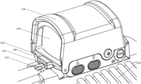
- FIG. 7 A is a left side view of the firearm accessory of FIG. 6 illustrating an integrated deflector according to embodiments of the invention.
- FIG. 7 B is a right side view of the firearm accessory of FIG. 6 illustrating an integrated deflector according to embodiments of the invention.
- FIG. 8 is a front view of the firearm accessory of FIG. 6 illustrating the integrated deflector.
- FIG. 9 is a bottom view of the firearm accessory of FIG. 6 illustrating the integrated deflector.
- Embodiments of the invention employ a gas discharge deflector to divert hot ejection gasses and debris from hitting a desired portion of the firearm, such as a sighting lens. Such hot ejection gasses and debris are generated when the firearm is discharged as a result of the rapidly burning gunpowder from a cartridge fired by the firearm.
- Embodiments are also directed to an accessory for a firearm that includes a deflector structured to alter a path of discharge gasses and/or debris after such gasses and debris pass a Loaded Chamber Indicator (LCI) of the firearm.
- the LCI indicates a presence of a cartridge within a firing chamber of the firearm, but openings within and around the LCI also provide a path for hot gasses and debris to strike accessories, which causes fouling and other deterioration, as described in detail below.
- FIG. 1 illustrates the typical position of a Loaded Chamber Indicator (LCI) 12 at the top of a firearm, in this case a pistol 10 , as well as a sighting accessory 14 .
- the sighting accessory 14 is a target sight commonly called a red dot sight.
- Such sights generally include a transparent surface, which is also called a sight glass 16 , near the LCI 12 , as is illustrated in FIG. 1 .
- Embodiments of the invention are applicable to any type of accessory where it is desired to shield the accessory or portions of the firearm itself from ejection gasses and/or debris expelled from a firing chamber of the firearm when the firearm is discharged.
- FIG. 2 illustrates an example portion of the sight glass 16 affected by the ejecting gas and debris from the cartridge when the weapon is fired.
- the hot gasses and debris from the burning gunpowder of the cartridge rush out of the firing chamber, past the openings made by the LCI 12 , toward the top of the pistol 10 and accessory 14 .
- Significant gas and debris may be ejected toward the transparent sight glass 16 of the target sight 14 .
- the exhaust from the explosion projects onto the lens 16 of the sight 14 .
- the particles 20 from the exhaust also collect onto the lens 16 over time. The collection of particles 20 quickly accumulates, and, if enough debris accumulates on the target sight, renders the sight difficult to use or even useless by blocking the view of the user.
- the gasses themselves may also negatively affect the material of the lens of the sight glass 16 , or coatings used in or on the sight glass.
- the particles 20 illustrated in FIG. 2 are only one example of how such particles may be distributed on a sight glass 16 . In reality, the particles 20 may have different patterns, shapes, densities, etc.
- FIG. 3 is a side perspective view of a pistol 110 having an LCI 112 and a targeting sight accessory 114 with a transparent lens or surface 116 . Further illustrated in FIG. 2 is a gas discharge deflector 120 , which functions to route hot gasses away from the targeting sight 114 when the weapon is being fired.
- the deflector 120 may be formed of any suitable material, such as plastic or metal.
- the deflector 120 is composed of glass-filled nylon, but may be formed of any material that is durable and may be formed or placed to block cartridge gasses and/or debris.
- the deflector 120 may be located between the LCI 112 and any accessory that is desired to be shielded from the discharge gasses. Or, the deflector 120 may block the discharge gasses and particles from a portion of the firearm 110 itself.
- the deflector 120 is inserted into a recess or pocket of the targeting sight 114 , and is retained by a crossbar 122 , as described in detail with reference to FIGS. 5 A and 5 B .
- Other retention mechanism may operate to maintain the deflector 120 in position.
- the position of the deflector 120 is such that it blocks some, most, or all of the exhausted gasses and debris that vent around the LCI 112 , so the gasses are blocked from reaching or affecting the sight glass 116 or other portion of the accessory 114 or firearm 110 . This reduces or eliminates the accumulation of debris from depositing onto the sight glass 116 or elsewhere.
- the deflector 120 also prevents or substantially reduces gasses from reaching the surface of the sight glass 116 , to prevent damage from the gas. Note, too, that the deflector 120 may be shaped and placed in such a way to not interfere with the operation or the function of the LCI 112 , thus allowing the LCI 112 to continue to function as a safety feature of the pistol 110 .
- the deflector 120 includes a scallop or indented shape 121 to help route the exhausted gasses away from the surface of the sight glass 116 .
- Other embodiments may have different shapes, of either the deflector 120 itself or any indentations 121 , but act to provide the same or similar function of preventing at least some of the gasses and debris from the exploding cartridge from reaching or accumulating on the surface of the sight glass 116 , or other portion of the firearm 110 or firearm accessory 114 desired to be shielded.
- FIG. 4 is a magnified perspective view of the pistol of FIG. 3 illustrating a modified gas discharge path 130 due to the presence of the gas discharge deflector 120 , according to embodiments of the invention.
- the LCI 112 is in the active position, which indicates that a cartridge is loaded into the firing chamber of the pistol 110 .
- the indication may be seen by a shooter through or around the accessory 114 , or the shooter may use his or her finger to determine whether the LCI 112 is in the active position, which indicates that a cartridge is present, or the inactive position, which indicates that the firing chamber is empty.
- FIG. 4 An example path 130 of the discharging gas and debris due to discharging the firearm is illustrated in FIG. 4 .
- these discharged gasses are directed upward from the chamber, around and through the LCI 112 toward the top of the firearm 110 .
- the gasses and debris strike the deflector 120 before reaching the forward lens 116 of the accessory 114 .
- the discharge deflector 120 creates a physical barrier preventing the gas and debris from reaching the lens 116 , and instead causes the discharge gasses and debris to be routed away from the firearm 110 , lens 116 , or other accessory or portion of an accessory desired to be so protected from the gas discharge.
- FIG. 4 An example path 130 of the discharging gas and debris due to discharging the firearm is illustrated in FIG. 4 . Initially these discharged gasses are directed upward from the chamber, around and through the LCI 112 toward the top of the firearm 110 .
- the gasses and debris strike the deflector 120 before reaching the forward lens 116 of the accessory 114 .
- FIG. 4 illustrates how the discharge deflector 120 blocks or interrupts the discharge path 130 of the blocked gasses so that they are diverted away from the firearm 110 and accessory 114 .
- the discharge gasses may not flow exactly as depicted in FIG. 4 , but in any case are generally directed away from the lens 116 and the accessory 114 .
- the gas discharge deflector 120 is removable from the accessory 114 , while in other cases the gas discharge deflector 120 may be integrated into the accessory itself.
- the gas discharge deflector 120 may be machined directly into the housing of the optical sight when the optical sight is manufactured as described with reference to FIGS. 6 - 9 below.
- the gas discharge deflector 120 and the accessory may be secured and/or removed from the firearm as a single unit.
- the gas discharge deflector 120 may be integrated into the firearm, such as a part of the LCI 112 itself.
- FIGS. 5 A and 5 B are cross-sectional views that illustrate how the gas discharge deflector 120 may be inserted into and retained by elements of the sighting accessory 114 .
- the gas deflector 120 is shaped with a groove 123 or indentation.
- the groove 123 of the gas deflector 120 is shaped to be mechanically retained by the crossbar 122 of the sighting accessory 114 .
- the sighting accessory 114 also includes a pocket or recess 140 shaped to generally accommodate the shape of the gas deflector 120 .
- a user inserts the gas deflector in the direction of the indicated arrows toward the recess 140 of the sighting accessory, where a lip of the groove 123 contacts the crossbar 122 .
- further pressure of the gas deflector 120 toward the recess 140 causes the lip of the groove 123 to deform or deflect under the rigid crossbar 122 , until finally snapping into place, as illustrated in FIG. 5 B .
- the recess 140 is sized to be slightly larger than the gas deflector 120 , and the gas deflector is forced downward while being pressed into the recess 140 .
- a combination of both of these movements occur, where the lip of the groove 123 may yield somewhat while the gas deflector 120 itself may deflect somewhat, until the groove 123 is positioned against the crossbar 122 as illustrated in FIG. 5 B .
- the gas deflector 120 may be removed by reversing the process, by pulling the gas deflector in the direction opposite the arrows illustrated in FIG. 5 A .
- the gas deflector 120 may be formed as a separate piece from the accessory 114 , but the gas deflector 120 is permanently fixed into the accessory during or after manufacture. In such an embodiment the gas deflector 120 may be held in place in the position illustrated in FIG. 5 B by, for example, glue or cement, as well as mechanical fasteners such as screws or pins. In this way the gas deflector 120 may be manufactured as a part separately from the accessory 114 , but permanently retained within the accessory.
- FIG. 6 is a side perspective view of a pistol 210 having an LCI 212 and a targeting sight accessory 214 with a transparent lens or surface 216 . Further illustrated in FIG. 6 is an integrated gas discharge deflector 220 , referred to as the deflector or integrated deflector, which, differently than being removable from the sight, is integrated into the targeting sight accessory 214 itself.
- the gas discharge deflector 220 functions to route hot gasses away from the targeting sight 214 when the weapon is being fired in the same or similar manner as the gas discharge deflector 120 described with reference to FIGS. 1 - 5 .
- One difference from the gas discharge deflector 120 is that the gas discharge deflector 220 is integrated directly into the targeting sight accessory 214 .
- the targeting sight 214 including the integrated deflector 220 may be located between the LCI 212 and any accessory that is desired to be shielded from the discharge gasses.
- the deflector 220 blocks the discharge gasses and particles from a portion of the firearm 210 itself.
- the position of the deflector 220 is such that it blocks some, most, or all of the exhausted gasses and debris that vent around the LCI 212 , so the gasses are blocked from reaching or affecting the sight glass 216 or other portion of the accessory 214 or firearm 210 . This reduces or eliminates the accumulation of debris from depositing onto the sight glass 216 or elsewhere.
- the deflector 220 also prevents or substantially reduces gasses from reaching the surface of the sight glass 216 , to prevent damage from the gas. Note, too, that the deflector 220 may be shaped and placed in such a way to not interfere with the operation or the function of the LCI 212 , thus allowing the LCI 212 to continue to function as a safety feature of the pistol 210 .
- the integrated deflector 220 includes an extension or lipped shape to help route the exhausted gasses away from the surface of the sight glass 216 .
- Other embodiments may have different shapes and sizes, but act to provide the same or similar function of preventing at least some of the gasses and debris from the exploding cartridge from reaching or accumulating on the surface of the sight glass 216 , or other portion of the firearm 210 or firearm accessory 214 desired to be shielded.
- the integrated deflector 220 may have a larger lip, or extend further away from the firearm accessory 214 than depicted in these illustrations.
- the integrated deflector 220 may include a scalloped or curved shape. Also, the integrated deflector 220 may be more wide or narrow than illustrated.
- FIG. 7 A is a left view of the firearm accessory 214 of FIG. 6 including the integrated deflector 220 .
- the integrated deflector 220 illustrated in these figures is an example embodiment, and may vary in size and shape, for instance.
- FIG. 7 B is a right hand view of the firearm accessory 214 illustrating the integrated deflector 220 and mounting tab 230 .
- FIG. 8 is a front view of the firearm accessory 214 illustrating the integrated deflector 220 , as well as the sight glass 216 and mounting tab 230 .
- FIG. 9 is a bottom view of the firearm accessory 214 that illustrates the mounting tab 230 , but, for the illustrated embodiment, the integrated deflector 220 is occluded in this view. In embodiments where the integrated deflector 220 is larger or extends beyond the mounting tab 230 , the integrated deflector 220 would be visible in this view.
- the purpose of the integrated deflector 220 is to block or divert hot gasses and debris escaping past the LCI 212 ( FIG.
- the integrated deflector 220 prevents contaminants reaching the sight glass 216 or other portions of the firearm accessory no matter what path the contaminants take toward the accessory.
- an article “comprising” or “which comprises” components A, B, and C can contain only components A, B, and C, or it can contain components A, B, and C along with one or more other components.
- an article “including” or “which includes” components A, B, and C can contain only components A, B, and C, or it can contain components A, B, and C along with one or more other components.
Landscapes
- Engineering & Computer Science (AREA)
- General Engineering & Computer Science (AREA)
- Physics & Mathematics (AREA)
- Optics & Photonics (AREA)
- Manufacturing & Machinery (AREA)
- Mechanical Engineering (AREA)
- Aiming, Guidance, Guns With A Light Source, Armor, Camouflage, And Targets (AREA)
Abstract
Description
Claims (17)
Priority Applications (1)
| Application Number | Priority Date | Filing Date | Title |
|---|---|---|---|
| US18/113,447 US12188747B2 (en) | 2020-08-24 | 2023-02-23 | Firearm gas discharge deflector |
Applications Claiming Priority (4)
| Application Number | Priority Date | Filing Date | Title |
|---|---|---|---|
| US202063069505P | 2020-08-24 | 2020-08-24 | |
| US17/410,955 US11614291B2 (en) | 2020-08-24 | 2021-08-24 | Firearm gas discharge deflector |
| US202263313172P | 2022-02-23 | 2022-02-23 | |
| US18/113,447 US12188747B2 (en) | 2020-08-24 | 2023-02-23 | Firearm gas discharge deflector |
Related Parent Applications (1)
| Application Number | Title | Priority Date | Filing Date |
|---|---|---|---|
| US17/410,955 Continuation-In-Part US11614291B2 (en) | 2020-08-24 | 2021-08-24 | Firearm gas discharge deflector |
Publications (2)
| Publication Number | Publication Date |
|---|---|
| US20230204324A1 US20230204324A1 (en) | 2023-06-29 |
| US12188747B2 true US12188747B2 (en) | 2025-01-07 |
Family
ID=86897461
Family Applications (1)
| Application Number | Title | Priority Date | Filing Date |
|---|---|---|---|
| US18/113,447 Active US12188747B2 (en) | 2020-08-24 | 2023-02-23 | Firearm gas discharge deflector |
Country Status (1)
| Country | Link |
|---|---|
| US (1) | US12188747B2 (en) |
Cited By (1)
| Publication number | Priority date | Publication date | Assignee | Title |
|---|---|---|---|---|
| US20240110765A1 (en) * | 2022-09-30 | 2024-04-04 | Primary Arms, Llc | Enclosed reflex sight for firearms, assembly, system and method |
Families Citing this family (1)
| Publication number | Priority date | Publication date | Assignee | Title |
|---|---|---|---|---|
| WO2025038577A1 (en) * | 2023-08-11 | 2025-02-20 | Sig Sauer, Inc. | Metal reinforced target sight |
Citations (9)
| Publication number | Priority date | Publication date | Assignee | Title |
|---|---|---|---|---|
| US790634A (en) * | 1904-08-01 | 1905-05-23 | Harry Hirsh | Automatic breech-sight for pistols. |
| US968139A (en) | 1910-05-23 | 1910-08-23 | Leon Irwin | Guard or deflector for side-ejection shoulder-firearms. |
| US1028032A (en) * | 1911-08-18 | 1912-05-28 | Ole Herman Johannes Krag | Automatic repeating firearm. |
| US1459284A (en) * | 1921-03-25 | 1923-06-19 | Declaye Joseph | Sight for firearms |
| US1992934A (en) | 1934-01-26 | 1935-03-05 | Edwin I Bamberger | Safety signal for firearms |
| US20130180152A1 (en) * | 2012-01-12 | 2013-07-18 | Walter Speroni | Tactical accessory mount, aiming device, and method for securing a tactical accessory to a pistol |
| WO2018102858A1 (en) * | 2016-12-07 | 2018-06-14 | Rise Mining Developments Pty Ltd | Improved stemming plugs |
| US20210325146A1 (en) | 2020-04-20 | 2021-10-21 | Sig Sauer, Inc. | Sight assembly and system with firearm status indicator |
| US11614291B2 (en) * | 2020-08-24 | 2023-03-28 | Sig Sauer, Inc. | Firearm gas discharge deflector |
-
2023
- 2023-02-23 US US18/113,447 patent/US12188747B2/en active Active
Patent Citations (9)
| Publication number | Priority date | Publication date | Assignee | Title |
|---|---|---|---|---|
| US790634A (en) * | 1904-08-01 | 1905-05-23 | Harry Hirsh | Automatic breech-sight for pistols. |
| US968139A (en) | 1910-05-23 | 1910-08-23 | Leon Irwin | Guard or deflector for side-ejection shoulder-firearms. |
| US1028032A (en) * | 1911-08-18 | 1912-05-28 | Ole Herman Johannes Krag | Automatic repeating firearm. |
| US1459284A (en) * | 1921-03-25 | 1923-06-19 | Declaye Joseph | Sight for firearms |
| US1992934A (en) | 1934-01-26 | 1935-03-05 | Edwin I Bamberger | Safety signal for firearms |
| US20130180152A1 (en) * | 2012-01-12 | 2013-07-18 | Walter Speroni | Tactical accessory mount, aiming device, and method for securing a tactical accessory to a pistol |
| WO2018102858A1 (en) * | 2016-12-07 | 2018-06-14 | Rise Mining Developments Pty Ltd | Improved stemming plugs |
| US20210325146A1 (en) | 2020-04-20 | 2021-10-21 | Sig Sauer, Inc. | Sight assembly and system with firearm status indicator |
| US11614291B2 (en) * | 2020-08-24 | 2023-03-28 | Sig Sauer, Inc. | Firearm gas discharge deflector |
Cited By (2)
| Publication number | Priority date | Publication date | Assignee | Title |
|---|---|---|---|---|
| US20240110765A1 (en) * | 2022-09-30 | 2024-04-04 | Primary Arms, Llc | Enclosed reflex sight for firearms, assembly, system and method |
| US12339098B2 (en) * | 2022-09-30 | 2025-06-24 | Primary Arms, Llc | Enclosed reflex sight for firearms, assembly, system and method |
Also Published As
| Publication number | Publication date |
|---|---|
| US20230204324A1 (en) | 2023-06-29 |
Similar Documents
| Publication | Publication Date | Title |
|---|---|---|
| US11614291B2 (en) | Firearm gas discharge deflector | |
| US12188747B2 (en) | Firearm gas discharge deflector | |
| US8342075B2 (en) | Receiver for an autoloading firearm | |
| US6311603B1 (en) | Firearm charging handle | |
| US5787631A (en) | Laser bore sight | |
| US20170261276A1 (en) | Rifle vented upper receiver | |
| US9714804B2 (en) | Firearm with safe axis firing pin and center aligned barrel | |
| US20130219763A1 (en) | Upper receiver device | |
| US7287351B1 (en) | Tactical sight for a semi-automatic hand gun | |
| US7305786B2 (en) | Pistol with loaded chamber indicator | |
| USRE48611E1 (en) | Semiautomatic firearm | |
| US20020112602A1 (en) | Muzzle brake | |
| US20170321978A1 (en) | Tactical rifle | |
| US5563362A (en) | Compensator attachment for a pistol | |
| US6834457B1 (en) | Tactical sight for a semi-automatic hand gun | |
| US11774206B2 (en) | Firearm muzzle brake | |
| US6481144B1 (en) | Firearm | |
| US11988481B2 (en) | Firearm shell casing catching system | |
| US20170198996A1 (en) | Gas block for firearm | |
| US5939657A (en) | Semiautomatic pistol and ammunition | |
| KR20020027339A (en) | Small arm with center or off-center line of sight | |
| US9915501B2 (en) | Weapon sight and weapon formed therewith | |
| EA006893B1 (en) | Firearm with a readily interchangeable bolt face | |
| US6367189B1 (en) | Non-protruding aiming apparatus for handguns | |
| US20060156608A1 (en) | Pistol |
Legal Events
| Date | Code | Title | Description |
|---|---|---|---|
| FEPP | Fee payment procedure |
Free format text: ENTITY STATUS SET TO UNDISCOUNTED (ORIGINAL EVENT CODE: BIG.); ENTITY STATUS OF PATENT OWNER: LARGE ENTITY |
|
| AS | Assignment |
Owner name: SIG SAUER, INC., NEW HAMPSHIRE Free format text: ASSIGNMENT OF ASSIGNORS INTEREST;ASSIGNORS:BOUDREAU, CHRISTOPHER J.;YORK, ANDREW W.;NICHOLS, JOHN P.;AND OTHERS;SIGNING DATES FROM 20230302 TO 20230307;REEL/FRAME:063144/0217 |
|
| STPP | Information on status: patent application and granting procedure in general |
Free format text: DOCKETED NEW CASE - READY FOR EXAMINATION |
|
| AS | Assignment |
Owner name: TD BANK, N.A., AS ADMINISTRATIVE AGENT, MASSACHUSETTS Free format text: SECURITY INTEREST;ASSIGNOR:SIG SAUER INC.;REEL/FRAME:064138/0600 Effective date: 20230630 |
|
| STPP | Information on status: patent application and granting procedure in general |
Free format text: NON FINAL ACTION MAILED |
|
| STPP | Information on status: patent application and granting procedure in general |
Free format text: RESPONSE TO NON-FINAL OFFICE ACTION ENTERED AND FORWARDED TO EXAMINER |
|
| STPP | Information on status: patent application and granting procedure in general |
Free format text: NOTICE OF ALLOWANCE MAILED -- APPLICATION RECEIVED IN OFFICE OF PUBLICATIONS |
|
| STPP | Information on status: patent application and granting procedure in general |
Free format text: AWAITING TC RESP., ISSUE FEE NOT PAID |
|
| STPP | Information on status: patent application and granting procedure in general |
Free format text: NOTICE OF ALLOWANCE MAILED -- APPLICATION RECEIVED IN OFFICE OF PUBLICATIONS |
|
| STPP | Information on status: patent application and granting procedure in general |
Free format text: PUBLICATIONS -- ISSUE FEE PAYMENT VERIFIED |
|
| STCF | Information on status: patent grant |
Free format text: PATENTED CASE |
|
| AS | Assignment |
Owner name: TD BANK, N.A, AS ADMINISTRATIVE AGENT, MASSACHUSETTS Free format text: SECURITY INTEREST;ASSIGNOR:SIG SAUER INC.;REEL/FRAME:071023/0417 Effective date: 20250423 |