US12183047B2 - Methods and systems for removing objects from view using machine learning - Google Patents
Methods and systems for removing objects from view using machine learning Download PDFInfo
- Publication number
- US12183047B2 US12183047B2 US18/048,649 US202218048649A US12183047B2 US 12183047 B2 US12183047 B2 US 12183047B2 US 202218048649 A US202218048649 A US 202218048649A US 12183047 B2 US12183047 B2 US 12183047B2
- Authority
- US
- United States
- Prior art keywords
- images
- machine
- distorted
- learned model
- vehicle
- Prior art date
- Legal status (The legal status is an assumption and is not a legal conclusion. Google has not performed a legal analysis and makes no representation as to the accuracy of the status listed.)
- Active, expires
Links
Images


Classifications
-
- G—PHYSICS
- G06—COMPUTING OR CALCULATING; COUNTING
- G06T—IMAGE DATA PROCESSING OR GENERATION, IN GENERAL
- G06T5/00—Image enhancement or restoration
- G06T5/77—Retouching; Inpainting; Scratch removal
-
- G—PHYSICS
- G06—COMPUTING OR CALCULATING; COUNTING
- G06T—IMAGE DATA PROCESSING OR GENERATION, IN GENERAL
- G06T7/00—Image analysis
- G06T7/50—Depth or shape recovery
- G06T7/55—Depth or shape recovery from multiple images
-
- G—PHYSICS
- G06—COMPUTING OR CALCULATING; COUNTING
- G06V—IMAGE OR VIDEO RECOGNITION OR UNDERSTANDING
- G06V10/00—Arrangements for image or video recognition or understanding
- G06V10/10—Image acquisition
- G06V10/16—Image acquisition using multiple overlapping images; Image stitching
-
- G—PHYSICS
- G06—COMPUTING OR CALCULATING; COUNTING
- G06V—IMAGE OR VIDEO RECOGNITION OR UNDERSTANDING
- G06V10/00—Arrangements for image or video recognition or understanding
- G06V10/20—Image preprocessing
- G06V10/26—Segmentation of patterns in the image field; Cutting or merging of image elements to establish the pattern region, e.g. clustering-based techniques; Detection of occlusion
- G06V10/273—Segmentation of patterns in the image field; Cutting or merging of image elements to establish the pattern region, e.g. clustering-based techniques; Detection of occlusion removing elements interfering with the pattern to be recognised
-
- G—PHYSICS
- G06—COMPUTING OR CALCULATING; COUNTING
- G06V—IMAGE OR VIDEO RECOGNITION OR UNDERSTANDING
- G06V10/00—Arrangements for image or video recognition or understanding
- G06V10/70—Arrangements for image or video recognition or understanding using pattern recognition or machine learning
- G06V10/764—Arrangements for image or video recognition or understanding using pattern recognition or machine learning using classification, e.g. of video objects
-
- G—PHYSICS
- G06—COMPUTING OR CALCULATING; COUNTING
- G06V—IMAGE OR VIDEO RECOGNITION OR UNDERSTANDING
- G06V10/00—Arrangements for image or video recognition or understanding
- G06V10/70—Arrangements for image or video recognition or understanding using pattern recognition or machine learning
- G06V10/77—Processing image or video features in feature spaces; using data integration or data reduction, e.g. principal component analysis [PCA] or independent component analysis [ICA] or self-organising maps [SOM]; Blind source separation
- G06V10/774—Generating sets of training patterns; Bootstrap methods, e.g. bagging or boosting
-
- G—PHYSICS
- G06—COMPUTING OR CALCULATING; COUNTING
- G06V—IMAGE OR VIDEO RECOGNITION OR UNDERSTANDING
- G06V10/00—Arrangements for image or video recognition or understanding
- G06V10/70—Arrangements for image or video recognition or understanding using pattern recognition or machine learning
- G06V10/77—Processing image or video features in feature spaces; using data integration or data reduction, e.g. principal component analysis [PCA] or independent component analysis [ICA] or self-organising maps [SOM]; Blind source separation
- G06V10/778—Active pattern-learning, e.g. online learning of image or video features
-
- G—PHYSICS
- G06—COMPUTING OR CALCULATING; COUNTING
- G06V—IMAGE OR VIDEO RECOGNITION OR UNDERSTANDING
- G06V10/00—Arrangements for image or video recognition or understanding
- G06V10/70—Arrangements for image or video recognition or understanding using pattern recognition or machine learning
- G06V10/82—Arrangements for image or video recognition or understanding using pattern recognition or machine learning using neural networks
-
- G—PHYSICS
- G06—COMPUTING OR CALCULATING; COUNTING
- G06V—IMAGE OR VIDEO RECOGNITION OR UNDERSTANDING
- G06V20/00—Scenes; Scene-specific elements
- G06V20/50—Context or environment of the image
- G06V20/56—Context or environment of the image exterior to a vehicle by using sensors mounted on the vehicle
- G06V20/58—Recognition of moving objects or obstacles, e.g. vehicles or pedestrians; Recognition of traffic objects, e.g. traffic signs, traffic lights or roads
-
- B—PERFORMING OPERATIONS; TRANSPORTING
- B60—VEHICLES IN GENERAL
- B60R—VEHICLES, VEHICLE FITTINGS, OR VEHICLE PARTS, NOT OTHERWISE PROVIDED FOR
- B60R1/00—Optical viewing arrangements; Real-time viewing arrangements for drivers or passengers using optical image capturing systems, e.g. cameras or video systems specially adapted for use in or on vehicles
- B60R1/20—Real-time viewing arrangements for drivers or passengers using optical image capturing systems, e.g. cameras or video systems specially adapted for use in or on vehicles
- B60R1/22—Real-time viewing arrangements for drivers or passengers using optical image capturing systems, e.g. cameras or video systems specially adapted for use in or on vehicles for viewing an area outside the vehicle, e.g. the exterior of the vehicle
-
- G—PHYSICS
- G06—COMPUTING OR CALCULATING; COUNTING
- G06T—IMAGE DATA PROCESSING OR GENERATION, IN GENERAL
- G06T2207/00—Indexing scheme for image analysis or image enhancement
- G06T2207/20—Special algorithmic details
- G06T2207/20081—Training; Learning
-
- G—PHYSICS
- G06—COMPUTING OR CALCULATING; COUNTING
- G06T—IMAGE DATA PROCESSING OR GENERATION, IN GENERAL
- G06T2207/00—Indexing scheme for image analysis or image enhancement
- G06T2207/20—Special algorithmic details
- G06T2207/20084—Artificial neural networks [ANN]
-
- G—PHYSICS
- G06—COMPUTING OR CALCULATING; COUNTING
- G06T—IMAGE DATA PROCESSING OR GENERATION, IN GENERAL
- G06T2207/00—Indexing scheme for image analysis or image enhancement
- G06T2207/30—Subject of image; Context of image processing
- G06T2207/30248—Vehicle exterior or interior
- G06T2207/30252—Vehicle exterior; Vicinity of vehicle
-
- G—PHYSICS
- G06—COMPUTING OR CALCULATING; COUNTING
- G06V—IMAGE OR VIDEO RECOGNITION OR UNDERSTANDING
- G06V2201/00—Indexing scheme relating to image or video recognition or understanding
- G06V2201/08—Detecting or categorising vehicles
Definitions
- Objects in images may occlude scenery. Further, in some instances, the objects in images may appear distorted. For example, cameras may be outfitted with fisheye lenses. A fisheye lens widens the field of view of a camera, however, objects within images acquired with such a camera are often unnaturally stretched or otherwise distorted. Distorted images may occlude scenery and may distract from the scenery. For example, distorted images captured by motor vehicle cameras and displayed in a console inside the vehicle may distract a driver from focusing on the road.
- a plurality of images may be used to construct a perspective. For example, multiple images may be stitched together and projected onto a surface in 3-dimensional space to create a 3-dimensional perspective, or rendering, of the environment captured by the multiple images.
- images with distorted objects are used to construct a 3-dimensional perspective, or are otherwise stitched together, apparent distortions pervade or are enhanced resulting in poor construction of the desired perspective.
- a perspective tainted with highly distorted objects may be considered unusable.
- a perspective when the purpose of constructing a perspective is to illustrate the surrounding environment or scenery captured by a plurality of images, objects within the plurality of images may be distracting and may obstruct useful, or desired, details of the environment. As such, distorted and undesired objects in images should be removed and replaced with a representative background in order to use the images to construct a useful and unobstructed perspective.
- One or more embodiments disclosed herein generally relate to a method for generating an unobstructed bowl view of a vehicle.
- the method includes obtaining a plurality of images from a plurality of cameras, wherein each of the plurality of cameras operates with a fisheye lens and is disposed on the vehicle and determining a plurality of depth fields, one for each image in the plurality of images.
- the method further includes detecting a plurality of distorted objects in the plurality of images with a first machine-learned model, wherein upon detection of a distorted object the first machine-learned model assigns a class distribution to the detected distorted object and estimating a distance of each distorted object from its associated camera using the plurality of depth fields.
- the method further includes assigning an object weight to each distorted object in the plurality of distorted objects, wherein the object weight is based on, at least, the class distribution and the estimated distance of the distorted object and removing at least one distorted objects from the plurality of images according to a criterion, wherein the criterion is based on the object weight assigned to the distorted object.
- the method further includes replacing each of the at least one removed distorted objects with a representative background, wherein there is one representative background for each of the at least one removed distorted objects and each representative background is generated by a second machine-learned model, stitching and projecting the plurality of images to form the unobstructed bowl view, and providing the unobstructed bowl view to one or more users of the vehicle, wherein the one or more users are local to the vehicle or remote to the vehicle.
- One or more embodiments disclosed herein generally relate to a non-transitory computer readable medium storing instructions executable by a computer processor, the instructions including functionality for obtaining a plurality of images from a plurality of cameras, wherein each of the plurality of cameras operates with a fisheye lens and is disposed on a vehicle and determining a plurality of depth fields, one for each image in the plurality of images.
- the instructions further include functionality for detecting a plurality of distorted objects in the plurality of images with a first machine-learned model, wherein upon detection of a distorted object the first machine-learned model assigns a class distribution to the detected distorted object and estimating a distance of each distorted object in the plurality of distorted objects from its associated camera using the plurality of depth fields.
- the instructions further include functionality for assigning an object weight to each distorted object in the plurality of distorted objects, wherein the object weight is based on, at least, the class distribution and estimated distance of the distorted object and removing at least one distorted objects from the plurality of images according to a criterion, wherein the criterion is based on the object weight assigned to the distorted object.
- the instructions further include functionality for replacing each of the at least one removed distorted objects with a representative background, wherein there is one representative background for each of the at least one removed distorted objects and each representative background is generated by a second machine-learned model, stitching and projecting the plurality of images to form an unobstructed bowl view, and providing the unobstructed bowl view to one or more users of the vehicle, wherein the one or more users are local to the vehicle or remote to the vehicle.
- One or more embodiments disclosed herein generally relate to a system that includes: a vehicle; a plurality of cameras, wherein each camera in the plurality of cameras is disposed on the vehicle, and wherein each camera in the plurality of cameras is outfitted with a fisheye lens; a depth estimator; a first machine-learned model; a second machine-learned model; an image masker; and a computer.
- the computer includes one or more processors, and a non-transitory computer readable medium storing instructions executable by the one or more computer processors, the instructions including functionality for obtaining a plurality of images from the plurality of cameras and determining, with the depth estimator, a plurality of depth fields, one for each image in the plurality of images.
- the instructions further include functionality for detecting a plurality of distorted objects in the plurality of images with the first machine-learned model, wherein upon detection of a distorted object the first machine-learned model assigns a class distribution to the detected distorted object and estimating a distance of each distorted object in the plurality of distorted objects from its associated camera using the plurality of depth fields.
- the instructions further include functionality for assigning an object weight to each distorted object in the plurality of distorted objects, wherein the object weight is based on, at least, the class distribution and estimated distance of the distorted object and removing, with the image masker, at least one distorted objects from the plurality of images according to a criterion, wherein the criterion is based on the object weight assigned to the distorted object.
- the instructions further include functionality for replacing each of the at least one removed distorted objects with a representative background, wherein there is one representative background for each of the at least one removed distorted objects and each representative background is generated by the second machine-learned model, stitching and projecting the plurality of images to form an unobstructed bowl view, and providing the unobstructed bowl view to one or more users of the vehicle, wherein the one or more users are local to the vehicle or remote to the vehicle.
- FIG. 1 depicts the field of view of a plurality of cameras disposed on a vehicle, in accordance with one or more embodiments.
- FIG. 2 depict an example plurality of images obtained with cameras, where each camera is outfitted with a fisheye lens, in accordance with one or more embodiments.
- FIG. 3 depicts the construction of a bowl view, in accordance with one or more embodiments.
- FIG. 4 depicts an example bowl view perspective, in accordance with one or more embodiments.
- FIG. 5 depicts a neural network in accordance with one or more embodiments.
- FIG. 6 depicts an object detection result in accordance with one or more embodiments.
- FIG. 7 A depicts an example streetview image in accordance with one or more embodiments.
- FIG. 7 B depicts an example depth field in accordance with one or more embodiments.
- FIG. 8 A shows an example image in accordance with one or more embodiments.
- FIG. 8 B shows an example image mask in accordance with one or more embodiments.
- FIG. 8 C shows an example inpainted image, in accordance with one or more embodiments.
- FIG. 9 depicts a generative adversarial network in accordance with one or more embodiments.
- FIG. 10 depicts an image processing pipeline in accordance with one or more embodiments.
- FIG. 11 A depicts an example bowl view perspective in accordance with one or more embodiments.
- FIG. 11 B depicts a corrected bowl view perspective, in accordance with one or more embodiments.
- FIG. 12 depicts a flowchart in accordance with one or more embodiments.
- FIG. 13 depicts a system in accordance with one or more embodiments.
- ordinal numbers e.g., first, second, third, etc.
- an element i.e., any noun in the application.
- the use of ordinal numbers is not to imply or create any particular ordering of the elements nor to limit any element to being only a single element unless expressly disclosed, such as using the terms “before,” “after,” “single,” and other such terminology. Rather, the use of ordinal numbers is to distinguish between the elements.
- a first element is distinct from a second element, and the first element may encompass more than one element and succeed (or precede) the second element in an ordering of elements.
- acoustic signal includes reference to one or more of such acoustic signals.
- any component described with regard to a figure in various embodiments disclosed herein, may be equivalent to one or more like-named components described with regard to any other figure.
- descriptions of these components will not be repeated with regard to each figure.
- each and every embodiment of the components of each figure is incorporated by reference and assumed to be optionally present within every other figure having one or more like-named components.
- any description of the components of a figure is to be interpreted as an optional embodiment which may be implemented in addition to, in conjunction with, or in place of the embodiments described with regard to a corresponding like-named component in any other figure.
- Embodiments disclosed herein describe methods and systems to remove objects, where the objects may be distorted, from images obtained from cameras disposed on a vehicle.
- the cameras on the vehicle are each outfitted with a fisheye lens.
- the cameras disposed on the vehicle may consist of one or more pin-hole (i.e., conventional) cameras.
- the fisheye lens while allowing for a wider field a view, distorts objects within its field of view.
- one or more obtained images may be stitched together to create a plurality of perspectives.
- One or more perspectives may appear 3-dimensional.
- one or more perspectives may be interactive and provide functionality for, at least, viewpoint translation and rotation.
- a perspective may be an interactive third-person perspective, where a user may view the surrounding of a vehicle from a viewpoint external to the vehicle.
- the process of image stitching may also result in distortion of objects in the image.
- the distorted objects may be distracting or obstruct useful image information. Consequently, a perspective containing distorted objects is without utility.
- distorted objects are detected and removed from images acquired with cameras outfitted with fisheye lenses. Further, distorted objects are replaced with semantically relevant representations. As such, generated perspectives are unobstructed and useful and depict scenery without obstacles and/or occlusions.
- FIG. 1 depicts a surrounding camera view ( 100 ) of a vehicle ( 102 ).
- a plurality of cameras may be disposed on a vehicle ( 102 ).
- the plurality of cameras is not explicitly illustrated.
- the location of each camera in the plurality of cameras disposed on the vehicle ( 102 ) is indicated in FIG. 1 with a circle.
- Each camera in the plurality of cameras may be relatively small compared to the vehicle ( 102 ). That is, due to its small size, a camera may be disposed on the vehicle ( 102 ) such that it is generally unnoticeable and does not hinder any functionality of the vehicle ( 102 ).
- FIG. 1 depicts a front-facing camera ( 104 ), two side-facing cameras ( 106 ), and a rear-facing camera ( 108 ).
- the number of cameras disposed on a vehicle ( 102 ), and the location of the cameras, is not limited to that depicted in FIG. 1 . In other embodiments, fewer or more cameras may be used.
- Each camera has a field of view (FOV). Field of view is used herein as a general term intended to indicate the extent of the observable world that is seen by a camera.
- the field of view is a solid angle through which the detector of a camera is sensitive to electromagnetic radiation.
- the field of view of each of the plurality of cameras is depicted in FIG. 1 with a dashed closed curve.
- the front-facing camera ( 104 ) has a front-facing FOV ( 110 ) such that the front-facing camera ( 104 ) may acquire images of the environment in front of the vehicle ( 102 ).
- the side-facing cameras ( 106 ) are associated with either the left-facing FOV ( 112 ) or right-facing FOV ( 114 ), where the terms “left” and “right” are relative to the top-down view of the vehicle ( 102 ) shown in FIG. 1 .
- the rear-facing camera ( 108 ) has a rear-facing FOV ( 116 ) such that the rear-facing camera ( 108 ) may acquire images of the environment to the rear of the vehicle ( 102 ).
- the fields of view of the plurality of cameras are overlapping.
- the entire surrounding environment of the vehicle ( 102 ) may be captured by the plurality of cameras.
- a set of images acquired by the plurality of cameras at a given instant in time can be said to capture the surroundings of the vehicle ( 102 ) at that time.
- each camera in the plurality of cameras disposed on the vehicle ( 102 ) is outfitted with a fisheye lens.
- one or more cameras disposed on the vehicle ( 102 ) is a pin-hole, or conventional, camera.
- a fisheye lens promotes a wide, or enlarged, field of view.
- Using fewer cameras provides an economical advantage as each additional camera has an associated cost.
- images acquired using a camera with a fisheye lens are often distorted. For example, FIG.
- the example plurality of fisheye images ( 200 ) is composed of four images: a front image ( 202 ) from a front-facing camera ( 104 ); a left image ( 204 ) from a side-facing camera ( 106 ) with a left-facing FOV ( 112 ); a right image ( 206 ) from a side-facing camera ( 106 ) with a right-facing FOV ( 114 ); and a rear image ( 208 ) from a rear-facing camera ( 108 ).
- the example plurality of fisheye images ( 200 ) forms a surrounding camera view ( 100 ). Further, the fields of view of the cameras used to acquire the example plurality of fisheye images ( 200 ) are overlapping. As seen, a proximate vehicle ( 210 ) appears in both the left image ( 204 ) and the right image ( 206 ). Additionally, portions of the images in the example plurality of fisheye images ( 200 ) are stretched or otherwise distorted. As an example, the street curb ( 212 ) highlighted in the front image ( 202 ) and the right image ( 206 ), which is known to be straight, is curved upward and is of non-uniform width throughout the images. Other instances of distorted objects may be identified in the example plurality of fisheye images ( 200 ).
- one or more obtained images may be stitched together to create a plurality of perspectives.
- One or more perspectives may appear 3-dimensional.
- one or more perspectives may be interactive and provide functionality for, at least, viewpoint translation and rotation.
- a bowl view perspective may be formed using the plurality of cameras disposed on a vehicle ( 102 ) .
- a bowl view perspective is constructed using a plurality of images which capture the surrounding environment of a vehicle ( 102 ). The surrounding environment is represented as a projection of the acquired images onto a fictional surface in 3-dimensional space.
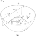
- FIG. 3 depicts a bowl view construction ( 300 ), in accordance with one or more embodiments.
- a vehicle ( 102 ) that has a plurality of cameras configured to capture images of the surrounding environment is shown in FIG. 3 .
- a representation of an image acquired by a camera on the vehicle ( 102 ) is shown as a frame ( 301 ).
- the placement of the frame ( 301 ) in FIG. 3 is intended to represent the extent of the environment captured by the image relative to the vehicle ( 102 ).
- the frame ( 301 ) may be thought to represent a left image ( 204 ).
- the vehicle in FIG. 3 is depicted as residing in a fictional bowl ( 304 ). It is emphasized that the bowl ( 304 ) is not a physical structure.
- the bowl ( 304 ) represents a non-planar, imaginary 2-dimensional surface.
- the 2-dimensional surface, or the bowl ( 304 ) may take shapes other than that depicted in FIG. 3 .
- a bowl view perspective is constructed by projecting the images acquired by the plurality of cameras disposed on the vehicle ( 102 ) onto the bowl ( 304 ).
- points are mapped from the acquired images onto the non-planar 2-dimensional surface (i.e., the bowl ( 304 )). Projecting the images to the bowl ( 304 ) may result in distortions, or further distortions, in the images.
- FIG. 3 depicts the mapping of some example points ( 306 ) from the frame ( 301 ), which represents an example image, to the bowl ( 304 ).
- Projection methods may include simple procedures such as ray tracing, mathematically based transformations, or computational algorithms.
- a projection method may borrow from the subfield of mathematics known as complex analysis to create a projection which respects a set of desired properties.
- the well-known Mercator projection which maps the geographic features of the substantially spherical Earth to a 2-dimensional world map, preserves conformality (i.e., parallel lines remain parallel through the projection).
- conformality i.e., parallel lines remain parallel through the projection.
- the resulting bowl view perspective fully captures the surrounding environment and may be perceived as 3-dimensional.
- the bowl view perspective allows for interactivity.
- a viewpoint ( 308 ) may be chosen from any location within the bowl.
- the viewpoint ( 308 ) may be translated or rotated within the bowl and the representation of the vehicle ( 102 ) and surrounding environment may be displayed to a user from the perspective of the viewpoint ( 308 ). Further, the viewpoint ( 308 ) may be positioned within the vehicle ( 102 ). Images from the plurality of cameras may be acquired continuously as the vehicle ( 102 ) travels. A bowl view perspective may be constructed from the images in real time. As such, the bowl view may be used to display the surrounding environment of the vehicle ( 102 ) even as the environment changes.
- FIG. 4 depicts an example bowl view perspective ( 400 ).
- the viewpoint ( 308 ) is positioned external and to the rear of the vehicle ( 102 ) but facing forward toward the vehicle ( 102 ).
- the bowl view perspective ( 400 ) provides a rendering of the surroundings of the vehicle ( 102 ).
- the bowl view perspective ( 400 ) may be updated in real time.
- Objects in the bowl view perspective ( 400 ), such as the adjacent vehicle ( 402 ) shown in FIG. 4 may appear distorted.
- the distortion of objects in the bowl view perspective ( 400 ) is the result of using fisheye lenes with the cameras disposed on the vehicle ( 102 ) and the process of projecting the images acquired with the cameras onto the bowl ( 304 ).
- Distorted objects are, at the very least, distracting.
- an end use of the bowl view perspective ( 400 ) is to provide a display of the landscape surrounding the vehicle ( 102 ) to a user.
- landscape refers to natural objects, such as trees and animals, and city infrastructure such as buildings and roads.
- vehicles and pedestrians obstruct the landscape.
- the obstruction of these objects is amplified when the objects are distorted. Consequently, a useful bowl view perspective ( 400 ) would be one with all distorted and undesired objects removed.
- the distortion of objects seen in the bowl view perspective ( 400 ) is generally amplified in the near field. That is, objects closer to the vehicle ( 102 ) will generally be displayed with greater distortion.
- a series of machine-learned models are applied to images acquired using cameras disposed on a vehicle ( 102 ) and outfitted with fisheye lenses to detect, identify, remove, and replace distorted and undesired objects.
- the result of these processes is a clean image without distorted and undesired (i.e., obstructive) objects that, when used to construct a bowl view perspective ( 400 ), produces a bowl view perspective ( 400 ) that displays an unobstructed landscape and is useful.
- Machine learning is the extraction of patterns and insights from data.
- the phrases “artificial intelligence”, “machine learning”, “deep learning”, and “pattern recognition” are often convoluted, interchanged, and used synonymously throughout the literature. This ambiguity arises because the field of “extracting patterns and insights from data” was developed simultaneously and disjointedly among a number of classical arts like mathematics, statistics, and computer science.
- machine learning, or machine-learned will be adopted herein, however, one skilled in the art will recognize that the concepts and methods detailed hereafter are not limited by this choice of nomenclature.
- a neural network may often be used as a subcomponent of a larger machine-learned model.
- a diagram of a neural network is shown in FIG. 5 .
- a neural network ( 500 ) may be graphically depicted as being composed of nodes ( 502 ), where in FIG. 5 any circle represents a node, and edges ( 504 ), shown in FIG. 5 as directed lines.
- the nodes ( 502 ) may be grouped to form layers ( 505 ).
- FIG. 5 displays four layers ( 508 , 510 , 512 , 514 ) of nodes ( 502 ) where the nodes ( 502 ) are grouped into columns, however, the grouping need not be as shown in FIG.
- edges ( 504 ) connect the nodes ( 502 ). Edges ( 504 ) may connect, or not connect, to any node(s) ( 502 ) regardless of which layer ( 505 ) the node(s) ( 502 ) is in. That is, the nodes ( 502 ) may be sparsely and residually connected. However, when every node ( 502 ) in a layer is connected to every node in an adjacent layer ( 502 ), the layer is said to be densely connected. If all layers in a neural network ( 500 ) are densely connected, the neural network ( 500 ) may be said to be a dense, or densely connected, neural network ( 500 ).
- a neural network ( 500 ) will have at least two layers ( 505 ), where the first layer ( 508 ) is considered the “input layer” and the last layer ( 514 ) is the “output layer”. Any intermediate layer ( 510 , 512 ) is usually described as a “hidden layer”.
- a neural network ( 500 ) may have zero or more hidden layers ( 510 , 512 ) and a neural network ( 500 ) with at least one hidden layer ( 510 , 512 ) may be described a “deep” neural network or a “deep learning method”.
- the machine-learned model is a deep neural network.
- a neural network ( 500 ) may have more than one node ( 502 ) in the output layer ( 514 ). In this case the neural network ( 500 ) may be referred to as a “multi-target” or “multi-output” network.
- Nodes ( 502 ) and edges ( 504 ) carry additional associations. Namely, every edge is associated with a numerical value. The edge numerical values, or even the edges ( 504 ) themselves, are often referred to as “weights” or “parameters”. While training a neural network ( 500 ), numerical values are assigned to each edge ( 504 ). Additionally, every node ( 502 ) is associated with a numerical variable and an activation function. Activation functions are not limited to any functional class, but traditionally follow the form
- A f ⁇ ( ⁇ i ⁇ ( incoming ) [ ( node ⁇ value ) i ⁇ ( edge ⁇ value ) i ] ) , ( 1 ) where i is an index that spans the set of “incoming” nodes ( 502 ) and edges ( 504 ) and ⁇ is a user-defined function.
- Incoming nodes ( 502 ) are those that, when viewed as a graph (as in FIG. 5 ), have directed arrows that point to the node ( 502 ) where the numerical value is being computed.
- Every node ( 502 ) in a neural network ( 500 ) may have a different associated activation function.
- activation functions are described by the function ⁇ by which it is composed. That is, an activation function composed of a linear function ⁇ may simply be referred to as a linear activation function without undue ambiguity.
- the neural network ( 500 ) When the neural network ( 500 ) receives an input, the input is propagated through the network according to the activation functions and incoming node ( 502 ) values and edge ( 504 ) values to compute a value for each node ( 502 ). That is, the numerical value for each node ( 502 ) may change for each received input. Occasionally, nodes ( 502 ) are assigned fixed numerical values, such as the value of 1, that are not affected by the input or altered according to edge ( 504 ) values and activation functions. Fixed nodes ( 502 ) are often referred to as “biases” or “bias nodes” ( 506 ), displayed in FIG. 5 with a dashed circle.
- the neural network ( 500 ) may contain specialized layers ( 505 ), such as a normalization layer (batch or layer-wise normalization may occur) or a dropout layer, or additional connection procedures, like concatenation.
- a normalization layer batch or layer-wise normalization may occur
- a dropout layer or additional connection procedures, like concatenation.
- the training procedure for the neural network ( 500 ) comprises assigning values to the edges ( 504 ).
- the edges ( 504 ) are assigned initial values. These values may be assigned randomly, assigned according to a prescribed distribution, assigned manually, or by some other assignment mechanism.
- the neural network ( 500 ) may act as a function, such that it may receive inputs and produce an output. As such, at least one input is propagated through the neural network ( 500 ) to produce an output.
- a given data set may be said to be composed of inputs and associated target(s), where the target(s) represent the “ground truth”, or the otherwise desired output. Such a data set is provided to the neural network ( 500 ) for training.
- the inputs are processed by the neural network ( 500 ) and the output of the neural network ( 500 ) is compared to the associated target(s) of the input data.
- the comparison of the neural network ( 500 ) output to the target(s) is typically performed by a so-called “loss function”; although other names for this comparison function such as “error function”, “objective function”, “value function”, and “cost function” are commonly employed.
- loss function many types of loss functions are available, such as the mean squared error function, however, the general characteristic of a loss function is that the loss function provides a numerical evaluation of the similarity between the neural network ( 500 ) output and the associated target(s).
- the loss function may also be constructed to impose additional constraints on the values assumed by the edges ( 504 ), for example, by adding a penalty term, which may be physics-based, or a regularization term.
- a penalty term which may be physics-based, or a regularization term.
- the goal of a training procedure is to alter the edge ( 504 ) values to promote similarity between the neural network ( 500 ) output and associated target(s) over the data set.
- the loss function is used to guide changes made to the edge ( 504 ) values, typically through a process called “backpropagation”.
- Backpropagation consists of computing the gradient of the loss function over the edge ( 504 ) values.
- the gradient indicates the direction of change in the edge ( 504 ) values that results in the greatest change to the loss function. Because the gradient is local to the current edge ( 504 ) values, the edge ( 504 ) values are typically updated by a “step” in the direction indicated by the gradient.
- the step size is often referred to as the “learning rate” and need not remain fixed during the training process. Additionally, the step size and direction may be informed by previously seen edge ( 504 ) values or previously computed gradients. Such methods for determining the step direction are usually referred to as “momentum” based methods.
- the neural network ( 500 ) will likely produce different outputs.
- the procedure of propagating at least one input through the neural network ( 500 ), comparing the neural network ( 500 ) output with the associated target(s) with a loss function, computing the gradient of the loss function with respect to the edge ( 504 ) values, and updating the edge ( 504 ) values with a step guided by the gradient is repeated until a termination criterion is reached.
- Common termination criteria are: reaching a fixed number of edge ( 504 ) updates, otherwise known as an iteration counter; a diminishing learning rate; noting no appreciable change in the loss function between iterations; reaching a specified performance metric as evaluated on the data or a separate hold-out data set.
- the objective may be to maximize the loss function (if maximization is the goal, the loss function is usually referred to as an objective or value function).
- maximization is the goal, the loss function is usually referred to as an objective or value function.
- the step may be in the direction of the gradient or in a direction opposite to the gradient.
- a machine-learned model architecture defines the entire structure of a machine-learned model. For example, in the case of a neural network ( 500 ), the number of hidden layers in the network, the type of activation function(s) used, and the number of outputs must be specified. Additionally, the use of, and location of, specialized layers such as batch normalization must be defined. Each of these choices, for example, the choice of how many hidden layers are in a neural network ( 500 ), is said to be a hyperparameter of the machine-learned model. In other words, a machine-learned model architecture specifies the hyperparameters surrounding the machine-learned model. Note that a machine-learned model architecture does not describe the values of the edges (weights, parameters) of the machine-learned model. These must be learned during training or are otherwise specified when using a pre-trained model.
- CNN convolutional neural network
- a CNN is similar to a neural network ( 500 ) in that it can technically be graphically represented by a series of edges ( 504 ) and nodes ( 502 ) grouped to form layers. However, it is more informative to view a CNN as structural groupings of weights; where here the term structural indicates that the weights within a group have a relationship.
- CNNs are widely applied when the data inputs also have a structural relationship, for example, a spatial relationship where one input is always considered “to the left” of another input. For example, an image has a structural relationship as each pixel has a directional relationship with respect to its adjacent pixels.
- a structural grouping, or group, of weights is herein referred to as a “filter”.
- the number of weights in a filter is typically much less than the number of inputs.
- the filters can be thought as “sliding” over, or convolving with, the inputs to form an intermediate output or intermediate representation of the inputs which still possesses a structural relationship.
- the intermediate outputs are often further processed with an activation function.
- Many filters may be applied to the inputs to form many intermediate representations. Additional filters may be formed to operate on the intermediate representations creating more intermediate representations. This process may be repeated as prescribed by a user.
- the filters when convolving with an input, may move in strides such that some components of the input (e.g., pixels) are skipped.
- Groupings of the intermediate output representations may be pooled, for example, by considering only the maximum value of a group in subsequent calculations. Strides and pooling may be used to downsample the intermediate representations.
- additional operations such as normalization, concatenation, dropout, and residual connections may be applied to the intermediate representations.
- intermediate representations may be upsampled, for example, through techniques such as transpose convolution. In a CNN there is a “final” group of intermediate representations, wherein no more filters act on these intermediate representations.
- the structural relationship of the final intermediate representations is ablated; a process known as “flattening”.
- the flattened representation is usually passed to a neural network ( 500 ), or a least a densely connected layer, to produce the final output.
- the neural network ( 500 ) is still considered part of the CNN.
- a CNN is trained, after initialization of the filter weights, and the edge ( 504 ) values of the internal neural network ( 500 ), if present, with the backpropagation process in accordance with a loss function.
- a first machine-learned model is trained and used to detect and classify distorted objects and undesired objects in images acquired from cameras disposed on the vehicle ( 102 ). Because CNNs are adept at processing images, in one or more embodiments, the first machine-learned model contains a CNN. In other embodiments, the first machine-learned model uses a visual transformer (ViT), which is another type of machine-learned model known to work well when processing images. Detection indicates the location of an object in an image.
- ViT visual transformer
- the location of an object may be indicated using a bounding box that circumscribes the portion of the image containing the object or the location of an object may be indicated pixelwise, where each pixel which is found to be associated with an object is flagged or given an identifier (i.e., instance segmentation).
- Detected objects are also classified by the first machine-learned model. For each detected object, a class probability distribution is returned.
- the class probability distribution indicates the probability that an object belongs to each class in a given set of classes.
- a set of classes may include the classes ⁇ ‘car’, ‘truck’, ‘pedestrian’, ‘cyclist’, ‘traffic signal’, ‘building’, etc. ⁇ .
- Machine-learned model architectures are described in the literature for the task of object detection and identification. These machine-learned models are usually based on one or more convolutional neural networks. For example, regional based CNNs (R-CNNs) and single shot detectors (SSDs) (and their variants) are commonly employed architectures. Any of these architectures, or others not explicitly referenced herein, may be used in the first machine-learned model without departing from the scope of this disclosure. However, even if one or more of these architectures is used in the first machine-learned model, the weights of the first machine-learned model must be determined through model training. It is unlikely that a pre-trained model, or a model where the weights are already provided, would accurately detect objects in the supplied images.
- a first training dataset is used to train the first machine-learned model.
- the first training dataset contains training images obtained from one or more cameras, each outfitted with a fisheye lens, disposed on a vehicle ( 102 ).
- the first training dataset contains both the original training images to be used as inputs to the machine-learned model and an annotated version of each training image which indicates the desired target(s).
- the annotation is performed manually by a human. Once the first training dataset is curated, the first training dataset may be used to train the first machine-learned model to detect and identify (through a class distribution) one or more distorted objects in one or more supplied images.
- FIG. 6 depicts an object detection result ( 600 ) of the first machine-learned model in accordance with one or more embodiments.
- the locations of various objects in the image are indicated with a bounding box returned by the first machine-learned model.
- the location of identified objects in an image may be identified on a per pixel basis.
- a class distribution is returned for each detected object.
- the class with the highest probability for each object is displayed on the object detection result ( 600 ) near the associated object.
- various vehicles are correctly detected and identified as well as a traffic signal.
- each image received from the cameras disposed on the vehicle ( 102 ) is processed by a depth estimator.
- the depth estimator returns a depth field for the image.
- the depth estimator consists of a physical depth sensor fixedly attached to the vehicle.
- the depth field indicates the distance, or depth, of every pixel in the image from the acquiring camera.
- FIG. 7 A depicts an example streetview image ( 701 ) received by a camera disposed on a vehicle ( 102 ).
- the example streetview image ( 701 ) is processed by the depth estimator.
- the depth estimator returns the depth field.
- FIG. 7 A is shown in FIG. 7 B .
- pixels (and thereby objects) which are further from the camera are darker, while those closer to the camera are lighter.
- the depth estimator returns an estimated distance for regions of an image, for example, regions where a distorted or otherwise undesired object has been detected.
- an object weight is assigned to each detected object in an image.
- the object weight is determined using the class distribution of the object and the estimated depth/distance of the object as determined by the depth estimator. For example, when the depth estimator returns a depth field of the image which contains the object, the object weight assigned to the object in the image is calculated using a user-defined function which accepts the class distribution of the object, as determined by the first machine-learned model, and the depth field of the image, as determined by the depth estimator, as inputs.
- the weight function is given as
- ow is the returned object weight associated with the object
- argmax(class distribution) returns the class name of the class with the highest probability
- avg(depth r ) returns the average pixelwise depth of the region r in the depth field that contains the object.
- EQ. 2 returns a higher valued object weight for objects nearer to the camera so long as the object is determined to be either a car, truck, or pedestrian.
- Embodiments are not limited to using the weight function given by EQ. 2.
- Weight functions may be tailored according to user-specific needs.
- distorted objects are removed from the image by an image masker.
- the image masker follows a threshold criterion, based on the assigned object weight of an object, to determine which objects should be removed (i.e., masked) in the image and which should be retained unaltered.
- the threshold criterion may specify that for an image with a detected distorted object with an assigned object weight greater than a value v, the pixels in the region of the distorted object in the image should be masked to values of zero.
- FIG. 8 A depicts an example image ( 801 ).
- two objects have been detected by the first machine-learned model; namely, a pedestrian ( 802 ) and a distant vehicle ( 803 ).
- the distance/depth of these objects is determined using a depth estimator, as previously described.
- An object weight is assigned to these two objects according to their class (pedestrian, vehicle) and distance/depth.
- EQ. 2 is used to determine the object weight for the pedestrian ( 802 ) and the distant vehicle ( 803 ) of FIG. 8 A .
- the distant vehicle ( 803 ) does not meet the threshold criterion of the image masker and should thus be retained.
- FIG. 8 B depicts an example mask ( 804 ) corresponding to the example image ( 801 ) of FIG. 8 A .
- the pixels corresponding to the detected pedestrian ( 802 ) of FIG. 8 A are flagged (masked portion ( 805 )).
- a second machine-learned model is trained and used to inpaint masked portions of images. Inpainting consists of filling in the masked region of an image with a generated image or pixel values which accurately represent the background of the masked portion. For example, in the case where a distorted car is detected in an image by the first machine-learned model and removed by the image masker, the second machine-learned model generates a region (or image) which represents the environment behind the distorted car. The generated region is used to replace the masked region of the affected image such that the distorted and obstructive object is removed and only the landscape remains visible in the affected image.
- the second machine-learned model may be an autoencoder or a generative adversarial network (GAN). In either case, the second machine-learned model may make use of CNNs.
- a GAN which uses deep convolutional neural networks may be referred to as a DCGAN.
- the benefit of using a DCGAN or autoencoder is that each is capable of generating regions for infilling that are semantically informed.
- FIG. 9 depicts the general architecture of DCGAN ( 900 ).
- the DCGAN ( 900 ) is composed of a generator ( 902 ) and a discriminator ( 904 ).
- the generator ( 902 ) and the discriminator ( 904 ) are each composed of blocks, represented in FIG. 9 as graphical blocks.
- the blocks may contain neural network layers that perform one or more convolutions and other processes such as normalization and dropout.
- the generator ( 902 ) can further be partitioned into an encoder ( 906 ) and a decoder ( 908 ).
- the generator accepts a masked image ( 910 ) and outputs an inpainting image ( 912 ) that can be used to fill in the masked region of the masked image ( 910 ).
- the encoder ( 906 ) is composed of convolutional blocks which downsample, or otherwise compress, the masked image ( 910 ).
- the decoder ( 908 ) decompresses the encoded input to form the inpainting image ( 912 ).
- the discriminator ( 904 ) which in one or more embodiments is also composed of convolutional blocks, accepts a proposed image ( 914 ) and outputs a continuous prediction indicating the discriminator's ( 904 ) belief that the proposed image ( 914 ) is generated (i.e., fake) or an original image (i.e., real).
- the discriminator ( 904 ) may be composed of one or more sub-discriminators acting at different spatial scales.
- the discriminator ( 904 ) may be composed of a local discriminator and a global discriminator.
- the local discriminator quantifies the realism of a generated inpainting image ( 912 ) and the global discriminator quantifies the probability that a generated inpainting image ( 912 ) portion belongs in the context of the masked image ( 910 ).
- the global discriminator quantifies the probability that a generated inpainting image ( 912 ) portion belongs in the context of the masked image ( 910 ).
- the DCGAN ( 900 ) is parameterized by a set of weights (or edge values). Training the DCGAN consists of determining the weights that minimize a given loss function.
- the loss function is typically split into two parts, namely, a reconstruction loss ( 916 ) and an adversarial loss ( 918 ).
- the generator receives input-target pairs of images. The input is an image with a masked portion. The target is the masked portion of the input image but without the mask applied.
- the reconstruction loss quantifies the difference between the original unmasked image and the generated image.
- the generator ( 902 ) is encouraged to produce inpainting images ( 912 ) that are similar to the original image prior to masking.
- the generator when computing the reconstruction loss during training, is given a second training dataset composed of one or more masked images ( 910 ) and associated target images with the correct background (only landscape) of the masked images ( 910 ). That is, the second training dataset may be artificially generated by masking regions in one or more images where a distorted object is not present.
- the discriminator ( 904 ) is given a third training dataset composed of original images (without masks) and images that have been masked, processed by the generator ( 902 ), and have had the masked region infilled by the output of the generator ( 902 ). That is, the discriminator ( 904 ) receives both “real” images and “fake” images where one or more regions of the fake images have been generated by the generator ( 902 ).
- the adversarial loss ( 918 ) quantifies the accuracy of the discriminator ( 904 ) when determining if an image received by the discriminator ( 904 ) is real or fake (i.e., produced by the generator ( 902 )).
- the adversarial loss is used to guide and update the weights of both the discriminator ( 904 ) and the generator ( 902 ).
- the weights of the generator ( 902 ) are updated to produce an inpainting image ( 912 ), which when used to infill a masked image ( 910 ), cannot be distinguished from an original (or real) image by the discriminator ( 904 ).
- the discriminator ( 904 ) of the DCGAN ( 900 ) may be discarded and the generator ( 902 ) may be used to process images with one or more removed distorted objects to generate the replacement backgrounds for the masked regions. For example, FIG.
- FIG. 8 C depicts an example inpainted image ( 806 ), where a representative background was generated by the trained generator ( 902 ) to replace the pedestrian ( 802 ) in the image of FIG. 8 A corresponding to the mask shown in FIG. 8 B .
- the generated representative background replaces the masked portion to produce the example inpainted image ( 806 ).
- the distant vehicle ( 803 ) is still present in the example inpainted image ( 806 ) because the pixels corresponding to the distant vehicle ( 803 ) were not masked by the image masker.
- the architectures of the generator ( 902 ) and the discriminator ( 904 ) of the DCGAN ( 900 ) of FIG. 9 are represented generally. In practice, these architectures may be altered to include additional components and functionality such as residual connections, normalization, and various convolutions taken at different length scales. As such, the second machine-learned model is not limited by the DCGAN ( 900 ) depicted in FIG. 9 .
- the loss function of the second machine-learned model (e.g., the DCGAN ( 900 ) of FIG. 9 ) is weighted according to the object weight determined for each detected object by the weight function (e.g., EQ. 2).
- the second machine-learned model is further promoted to generate realistic infill backgrounds for the objects with the greatest expected level of distortion and/or the objects most desired to be replaced with landscape (e.g., other vehicles).
- the depth estimator and weight function may be applied to images without masked objects.
- the second training dataset may have object weights assigned to artificially masked regions to promote the reconstruction of nearfield backgrounds (landscapes).
- the loss function of the second machine-learned model is weighted according to object weights, where the object weights may be calculated for detected distorted objects and/or artificially masked regions.
- FIG. 10 depicts the general process of removing distorted objects from an image and replacing the distorted object regions with a representative background. This process is referred to herein as the image processing pipeline ( 1000 ).
- an image A ( 1002 ) is received from a camera disposed on a vehicle ( 102 ).
- Image A ( 1002 ) may undergo any pre-processing step known in the art, such as resizing, normalization, and color correction.
- image A ( 1002 ) is processed by the depth estimator ( 1004 ).
- the depth estimator ( 1004 ) returns a depth field for image A ( 1002 ).
- Image A ( 1002 ) is also processed by a trained object detection model ( 1006 ), also described herein as the first machine-learned model.
- the object detection model ( 1006 ) detects distorted objects in the image A ( 1002 ).
- the object detection model ( 1006 ) returns the location and class distribution of detected distorted objects in image A ( 1002 ).
- the depth estimator ( 1004 ) acts on Image A ( 1002 ) after the object detection model ( 1006 ) has detected and identified objects in Image A ( 1002 ). In this case, the depth estimator ( 1004 ) returns a distance (or depth) for each detected object in Image A.
- the depth estimator ( 1004 ) is shown as a pre-step to the object detection model ( 1006 ) in FIG. 10 .
- the depth field (or distance/depth of objects), location, and class distribution of detected objects are processed by an image masker ( 1008 ).
- the image masker ( 1008 ) applies a user-defined weight function to determine an object weight for each detected object in image A ( 1002 ). Then, according to a criterion, the image masker ( 1008 ) masks regions of detected objects (e.g., distorted vehicles) according to their associated object weight.
- the image masker ( 1008 ) returns a masked version of image A ( 1002 ).
- the masked image is passed to the inpainting model ( 1010 ), also known as the second machine-learned model.
- the inpainting model ( 1010 ) processes the masked image to generate a representative background for each masked region in the masked image.
- the inpainting model ( 1010 ) further replaces the masked regions of the masked image with their respective representative backgrounds to form a cleaned version of image A ( 1002 ). While replacing a masked region with a representative background, the inpainting model ( 1010 ) may blend the representative background with one or more adjacent pixels in the unmasked portion of the masked image. Blending promotes a smooth transition between the inserted representative background and unmasked portion of the image.
- cleaned image A ( 1012 ).
- Cleaned image A ( 1012 ) is like image A ( 1002 ) but has all detected and distorted objects removed and replaced with representative backgrounds.
- Cleaned image A ( 1012 ) may be stitched with other images processed in a similar manner.
- Cleaned image A ( 1012 ) may be used to generate a bowl view perspective.
- FIG. 11 A shows the same example bowl view perspective ( 400 ) depicted in FIG. 4 .
- a plurality of images is collected from a plurality of cameras disposed on the vehicle ( 102 ).
- the plurality of images is stitched and projected onto a bowl ( 304 ) to form a bowl view perspective ( 400 ) as previously described.
- an adjacent vehicle ( 402 ) is captured in the plurality of images.
- the adjacent vehicle ( 402 ) appears distorted. The distortion occurs due to, in part, the use of fisheye lenses with the plurality of cameras disposed on the vehicle ( 402 ).
- the distorted adjacent vehicle ( 402 ) is distracting and obstructs the landscape in the bowl view perspective ( 400 ).
- Each image in the plurality of images is processed according to the image processing pipeline ( 1000 ) of FIG. 10 resulting in a plurality of cleaned images.
- FIG. 11 B depicts a corrected bowl view perspective ( 1100 ) constructed using the plurality of cleaned images.
- the region containing the adjacent vehicle ( 402 ) is replaced with a representative background ( 1102 ) in FIG. 11 B .
- the corrected bowl view perspective ( 1100 ), as seen in FIG. 11 B is useful and displays a landscape that is not obstructed by distorted objects.
- FIG. 12 depicts a flowchart outlining the process of providing a bowl view where distorted objects have been removed.
- a plurality of images is obtained.
- the plurality of images is acquired using a plurality of cameras disposed on a vehicle.
- Each camera in the plurality of cameras is outfitted with a fisheye lens.
- the plurality of cameras is capable of capturing images in real time.
- the plurality of images obtained from the plurality of cameras has an associated time.
- a plurality of depth fields, one for each image in the plurality of images is determined using a depth estimator ( 1004 ).
- Each depth field indicates the distance of each pixel in the associated image (from the plurality of images) from the camera (from the plurality of cameras) that was used to capture the associated image.
- a first machine-learned model detects a plurality of distorted objects in the plurality of images. Each detected distorted object is assigned a class distribution by the first machine-learned model. The class distribution represents the probability that a detected distorted object belongs to a given class. The location of each distorted object in the plurality of distorted objects is output by the first machine-learned model. The location information of a distorted object may be returned by the first machine-learned model as a bounding box or masked pixel map.
- each detected distorted object from its associated camera is estimated using the plurality of depth fields according to Block 1208 .
- pixel distances from a depth field are averaged over a region which contains a detected object to produce a distance estimate for that object.
- an object weight is assigned to each distorted object based on the class distribution and estimated distance of the distorted object.
- EQ. 2 is used to calculate the object weight of a detected object. With an object weight assigned to each distorted object in the plurality of distorted objects, at least one distorted objects are removed from the plurality of images, as shown in Block 1212 .
- a distorted object is removed from an image according to a criterion, where the criterion is based on the object weight assigned to the distorted object.
- the criterion is a simple threshold where a distorted object is removed if its assigned object weight is greater than or equal to a user-defined threshold value (e.g., threshold value may be set to 6.2).
- Distorted objects may be removed from an image by masking the pixels in the image in the regions determined to contain the distorted objects.
- the processes of Blocks 1208 , 1210 , and 1212 are performed by an image masker ( 1008 ).
- the at least one removed distorted objects are replaced with at least one representative backgrounds, where there is a one-to-one correspondence between representative backgrounds and removed distorted objects.
- Each representative background is generated by a second machine-learned model.
- the second machine-learned model receives the plurality of images where at least one distorted objects have been removed (likely covered with a mask) and returns a representative background for each of the plurality of images.
- the second machine-learned model replaces the regions in the plurality of images where distorted objects have been removed with the representative backgrounds.
- the plurality of images, now with distorted images replaced by representative backgrounds is stitched and projected to form a bowl view.
- the bowl view is provided to one or more users of the vehicle, where the one or more users may be local to the vehicle or remote to the vehicle.
- a bowl view may be displayed to users within the vehicle (e.g., the driver or passenger of the vehicle, while the vehicle is in operation) or to users external to the vehicle (e.g., a viewer virtually travelling with the vehicle).
- the bowl view, formed according to the flow chart of FIG. 12 does not contain distorted objects and provides an unobstructed view of the landscape surrounding the vehicle.
- Embodiments of the invention may be implemented on virtually any type of computing system, regardless of the platform being used.
- the image processing pipeline ( 1000 ) discussed in embodiments herein may be implemented as a computing system as shown in FIG. 13 or include one or more computing systems.
- Such a computing system may be one or more mobile devices (e.g., laptop computer, smart phone, personal digital assistant, tablet computer, or other mobile device), desktop computers, servers, blades in a server chassis, one or more ECUs in a vehicle or any other type of computing device or devices that includes at least the minimum processing power, memory, and input and output device(s) to perform one or more embodiments of the invention.
- mobile devices e.g., laptop computer, smart phone, personal digital assistant, tablet computer, or other mobile device
- desktop computers e.g., servers, blades in a server chassis, one or more ECUs in a vehicle or any other type of computing device or devices that includes at least the minimum processing power, memory, and input and output device(s) to perform one or more embodiment
- the computing system ( 1300 ) may include one or more computer processor(s) ( 1302 ), associated memory ( 1304 ) (e.g., random access memory (RAM), cache memory, flash memory, etc.), one or more storage device(s) ( 1306 ) (e.g., a hard disk, an optical drive such as a compact disk (CD) drive or digital versatile disk (DVD) drive, a flash memory stick, etc.), and numerous other elements and functionalities.
- the computer processor(s) ( 1302 ) may be an integrated circuit for processing instructions.
- the computer processor(s) may be one or more cores, or micro-cores of a processor.
- the computing system ( 1300 ) may also include one or more input device(s) ( 1310 ), such as a touchscreen, keyboard, mouse, microphone, touchpad, electronic pen, or any other type of input device. Further, the computing system ( 1300 ) may include one or more output device(s) ( 1308 ), such as a screen (e.g., a liquid crystal display (LCD), a plasma display, touchscreen, cathode ray tube (CRT) monitor, projector, or other display device), a printer, external storage, or any other output device. One or more of the output device(s) may be the same or different from the input device(s).
- input device(s) such as a touchscreen, keyboard, mouse, microphone, touchpad, electronic pen, or any other type of input device.
- the computing system ( 1300 ) may include one or more output device(s) ( 1308 ), such as a screen (e.g., a liquid crystal display (LCD), a plasma display, touchscreen, cathode ray tube (CRT
- the computing system ( 1300 ) may be connected to a network ( 1312 ) (e.g., a local area network (LAN), a wide area network (WAN) such as the Internet, mobile network, or any other type of network) via a network interface connection (not shown).
- the input and output device(s) may be locally or remotely (e.g., via the network ( 1312 )) connected to the computer processor(s) ( 1302 ), memory ( 1304 ), and storage device(s) ( 1306 ).
- Software instructions in the form of computer readable program code to perform embodiments of the invention may be stored, in whole or in part, temporarily or permanently, on a non-transitory computer readable medium such as a CD, DVD, storage device, a diskette, a tape, flash memory, physical memory, or any other computer readable storage medium.
- the software instructions may correspond to computer readable program code that when executed by a processor(s), is configured to perform embodiments of the invention.
- one or more elements of the aforementioned computing system ( 1300 ) may be located at a remote location and be connected to the other elements over a network ( 1312 ). Further, one or more embodiments of the invention may be implemented on a distributed system having a plurality of nodes, where each portion of the invention may be located on a different node within the distributed system.
- the node corresponds to a distinct computing device.
- the node may correspond to a computer processor with associated physical memory.
- the node may alternatively correspond to a computer processor or micro-core of a computer processor with shared memory and/or resources.
Landscapes
- Engineering & Computer Science (AREA)
- Theoretical Computer Science (AREA)
- General Physics & Mathematics (AREA)
- Physics & Mathematics (AREA)
- Multimedia (AREA)
- Computer Vision & Pattern Recognition (AREA)
- Evolutionary Computation (AREA)
- Databases & Information Systems (AREA)
- Health & Medical Sciences (AREA)
- Computing Systems (AREA)
- Artificial Intelligence (AREA)
- General Health & Medical Sciences (AREA)
- Medical Informatics (AREA)
- Software Systems (AREA)
- Image Processing (AREA)
Abstract
Description
where i is an index that spans the set of “incoming” nodes (502) and edges (504) and ƒ is a user-defined function. Incoming nodes (502) are those that, when viewed as a graph (as in
and rectified linear unit function ƒ(x)=max(0, x), however, many additional functions are commonly employed. Every node (502) in a neural network (500) may have a different associated activation function. Often, as a shorthand, activation functions are described by the function ƒ by which it is composed. That is, an activation function composed of a linear function ƒ may simply be referred to as a linear activation function without undue ambiguity.
where ow is the returned object weight associated with the object, argmax(class distribution) returns the class name of the class with the highest probability, and avg(depthr) returns the average pixelwise depth of the region r in the depth field that contains the object. In other words, EQ. 2 returns a higher valued object weight for objects nearer to the camera so long as the object is determined to be either a car, truck, or pedestrian. Embodiments are not limited to using the weight function given by EQ. 2. Weight functions may be tailored according to user-specific needs.
Claims (20)
Priority Applications (1)
| Application Number | Priority Date | Filing Date | Title |
|---|---|---|---|
| US18/048,649 US12183047B2 (en) | 2022-10-21 | 2022-10-21 | Methods and systems for removing objects from view using machine learning |
Applications Claiming Priority (1)
| Application Number | Priority Date | Filing Date | Title |
|---|---|---|---|
| US18/048,649 US12183047B2 (en) | 2022-10-21 | 2022-10-21 | Methods and systems for removing objects from view using machine learning |
Publications (3)
| Publication Number | Publication Date |
|---|---|
| US20240135667A1 US20240135667A1 (en) | 2024-04-25 |
| US20240233304A9 US20240233304A9 (en) | 2024-07-11 |
| US12183047B2 true US12183047B2 (en) | 2024-12-31 |
Family
ID=91282191
Family Applications (1)
| Application Number | Title | Priority Date | Filing Date |
|---|---|---|---|
| US18/048,649 Active 2043-03-14 US12183047B2 (en) | 2022-10-21 | 2022-10-21 | Methods and systems for removing objects from view using machine learning |
Country Status (1)
| Country | Link |
|---|---|
| US (1) | US12183047B2 (en) |
Cited By (2)
| Publication number | Priority date | Publication date | Assignee | Title |
|---|---|---|---|---|
| US20240027771A1 (en) * | 2017-03-27 | 2024-01-25 | Avegant Corp. | Steerable high-resolution display |
| US12450879B2 (en) * | 2020-11-10 | 2025-10-21 | Panasonic Intellectual Property Management Co., Ltd. | Data creation system, learning system, estimation system, processing device, evaluation system, data creation method, and program |
Families Citing this family (1)
| Publication number | Priority date | Publication date | Assignee | Title |
|---|---|---|---|---|
| JP7852526B2 (en) * | 2023-01-25 | 2026-04-28 | トヨタ自動車株式会社 | Display control device |
Citations (15)
| Publication number | Priority date | Publication date | Assignee | Title |
|---|---|---|---|---|
| US20200242774A1 (en) * | 2019-01-25 | 2020-07-30 | Nvidia Corporation | Semantic image synthesis for generating substantially photorealistic images using neural networks |
| US11580673B1 (en) * | 2019-06-04 | 2023-02-14 | Duke University | Methods, systems, and computer readable media for mask embedding for realistic high-resolution image synthesis |
| US11636570B2 (en) * | 2021-04-01 | 2023-04-25 | Adobe Inc. | Generating digital images utilizing high-resolution sparse attention and semantic layout manipulation neural networks |
| US20230127188A1 (en) * | 2021-10-21 | 2023-04-27 | Melown Technologies Se | Method for removing objects from texture |
| US20230192124A1 (en) * | 2021-12-21 | 2023-06-22 | Waymo Llc | Methods and Systems for Providing Remote Assistance to an Autonomous Vehicle |
| US11694089B1 (en) * | 2020-02-04 | 2023-07-04 | Rockwell Collins, Inc. | Deep-learned photorealistic geo-specific image generator with enhanced spatial coherence |
| US11763430B2 (en) * | 2020-05-13 | 2023-09-19 | Adobe Inc. | Correcting dust and scratch artifacts in digital images |
| US20230302999A1 (en) * | 2022-03-23 | 2023-09-28 | Isuzu Motors Limited | Vehicle rearward monitoring system and vehicle rearward monitoring method |
| US20230319218A1 (en) * | 2022-04-01 | 2023-10-05 | Nvidia Corporation | Image stitching with dynamic seam placement based on ego-vehicle state for surround view visualization |
| US20230356728A1 (en) * | 2018-03-26 | 2023-11-09 | Nvidia Corporation | Using gestures to control machines for autonomous systems and applications |
| US11823061B2 (en) * | 2019-01-14 | 2023-11-21 | Cambia Health Solutions, Inc. | Systems and methods for continual updating of response generation by an artificial intelligence chatbot |
| US11854203B1 (en) * | 2020-12-18 | 2023-12-26 | Meta Platforms, Inc. | Context-aware human generation in an image |
| US11861884B1 (en) * | 2023-04-10 | 2024-01-02 | Intuit, Inc. | Systems and methods for training an information extraction transformer model architecture |
| US11875221B2 (en) * | 2020-10-16 | 2024-01-16 | Adobe Inc. | Attribute decorrelation techniques for image editing |
| US11893713B1 (en) * | 2023-04-28 | 2024-02-06 | Intuit, Inc. | Augmented diffusion inversion using latent trajectory optimization |
-
2022
- 2022-10-21 US US18/048,649 patent/US12183047B2/en active Active
Patent Citations (15)
| Publication number | Priority date | Publication date | Assignee | Title |
|---|---|---|---|---|
| US20230356728A1 (en) * | 2018-03-26 | 2023-11-09 | Nvidia Corporation | Using gestures to control machines for autonomous systems and applications |
| US11823061B2 (en) * | 2019-01-14 | 2023-11-21 | Cambia Health Solutions, Inc. | Systems and methods for continual updating of response generation by an artificial intelligence chatbot |
| US20200242774A1 (en) * | 2019-01-25 | 2020-07-30 | Nvidia Corporation | Semantic image synthesis for generating substantially photorealistic images using neural networks |
| US11580673B1 (en) * | 2019-06-04 | 2023-02-14 | Duke University | Methods, systems, and computer readable media for mask embedding for realistic high-resolution image synthesis |
| US11694089B1 (en) * | 2020-02-04 | 2023-07-04 | Rockwell Collins, Inc. | Deep-learned photorealistic geo-specific image generator with enhanced spatial coherence |
| US11763430B2 (en) * | 2020-05-13 | 2023-09-19 | Adobe Inc. | Correcting dust and scratch artifacts in digital images |
| US11875221B2 (en) * | 2020-10-16 | 2024-01-16 | Adobe Inc. | Attribute decorrelation techniques for image editing |
| US11854203B1 (en) * | 2020-12-18 | 2023-12-26 | Meta Platforms, Inc. | Context-aware human generation in an image |
| US11636570B2 (en) * | 2021-04-01 | 2023-04-25 | Adobe Inc. | Generating digital images utilizing high-resolution sparse attention and semantic layout manipulation neural networks |
| US20230127188A1 (en) * | 2021-10-21 | 2023-04-27 | Melown Technologies Se | Method for removing objects from texture |
| US20230192124A1 (en) * | 2021-12-21 | 2023-06-22 | Waymo Llc | Methods and Systems for Providing Remote Assistance to an Autonomous Vehicle |
| US20230302999A1 (en) * | 2022-03-23 | 2023-09-28 | Isuzu Motors Limited | Vehicle rearward monitoring system and vehicle rearward monitoring method |
| US20230319218A1 (en) * | 2022-04-01 | 2023-10-05 | Nvidia Corporation | Image stitching with dynamic seam placement based on ego-vehicle state for surround view visualization |
| US11861884B1 (en) * | 2023-04-10 | 2024-01-02 | Intuit, Inc. | Systems and methods for training an information extraction transformer model architecture |
| US11893713B1 (en) * | 2023-04-28 | 2024-02-06 | Intuit, Inc. | Augmented diffusion inversion using latent trajectory optimization |
Cited By (3)
| Publication number | Priority date | Publication date | Assignee | Title |
|---|---|---|---|---|
| US20240027771A1 (en) * | 2017-03-27 | 2024-01-25 | Avegant Corp. | Steerable high-resolution display |
| US12360378B2 (en) * | 2017-03-27 | 2025-07-15 | Avegant Corp. | Steerable high-resolution display |
| US12450879B2 (en) * | 2020-11-10 | 2025-10-21 | Panasonic Intellectual Property Management Co., Ltd. | Data creation system, learning system, estimation system, processing device, evaluation system, data creation method, and program |
Also Published As
| Publication number | Publication date |
|---|---|
| US20240135667A1 (en) | 2024-04-25 |
| US20240233304A9 (en) | 2024-07-11 |
Similar Documents
| Publication | Publication Date | Title |
|---|---|---|
| US12183047B2 (en) | Methods and systems for removing objects from view using machine learning | |
| CN114424250B (en) | Structural modeling | |
| CN114764868A (en) | Image processing method, image processing device, electronic equipment and computer readable storage medium | |
| JP7036610B2 (en) | Learning methods and programs | |
| US20240371035A1 (en) | Camera and lidar cross-sensor calibration | |
| US11367206B2 (en) | Edge-guided ranking loss for monocular depth prediction | |
| US12110009B2 (en) | Parking space detection method and system | |
| Haro | Shape from silhouette consensus | |
| CN120260014B (en) | Image fusion driven anti-collision recognition method and system | |
| CN119832029A (en) | Implicit image enhancement and optical flow estimation method based on multi-mode collaborative optimization | |
| CN120318406A (en) | Multimodal three-dimensional model building method, device and readable medium | |
| Kim et al. | Image motion blur removal algorithm based on generative adversarial network | |
| Shit et al. | Review and evaluation of recent advancements in image dehazing techniques for vision improvement and visualization | |
| CN116563303B (en) | Scene generalizable interactive radiation field segmentation method | |
| CN119338668A (en) | Video image space conversion method based on deep learning | |
| CN118071939A (en) | A scene reconstruction method and device based on neural radiation field | |
| CN116912905A (en) | Micro-expression recognition method, electronic device, storage medium | |
| Qi | Dynamic scene blind image deblurring based on local and non-local features | |
| Yang et al. | Multibranch semantic image segmentation model based on edge optimization and category perception | |
| Malothu et al. | Attention-based global-local cyclegan with enhanced dragonfly optimization for video dehazing and haze detection using Wavelet-DNN | |
| Ke et al. | Semantic Segmentation Network combining Gaussian Perception and Iterative Multi-Scale Attention | |
| CN116894959B (en) | Infrared small target detection method and device based on mixed scale and focusing network | |
| CN110599542A (en) | Method and device for local mapping of adaptive VSLAM (virtual local area model) facing to geometric area | |
| Zhen et al. | Inertial sensor aided multi-image nonuniform motion blur removal based on motion decomposition | |
| Chang et al. | Homography-guided stereo matching for wide-baseline image interpolation |
Legal Events
| Date | Code | Title | Description |
|---|---|---|---|
| FEPP | Fee payment procedure |
Free format text: ENTITY STATUS SET TO UNDISCOUNTED (ORIGINAL EVENT CODE: BIG.); ENTITY STATUS OF PATENT OWNER: LARGE ENTITY |
|
| STPP | Information on status: patent application and granting procedure in general |
Free format text: DOCKETED NEW CASE - READY FOR EXAMINATION |
|
| AS | Assignment |
Owner name: VALEO NORTH AMERICA, INC., MICHIGAN Free format text: ASSIGNMENT OF ASSIGNORS INTEREST;ASSIGNORS:BHANUSHALI, JAGDISH;GROTH, PETER;REEL/FRAME:064765/0205 Effective date: 20221018 Owner name: VALEO SCHALTER UND SENSOREN GMBH, GERMANY Free format text: ASSIGNMENT OF ASSIGNORS INTEREST;ASSIGNOR:VALEO NORTH AMERICA, INC.;REEL/FRAME:064765/0228 Effective date: 20230830 |
|
| STPP | Information on status: patent application and granting procedure in general |
Free format text: NON FINAL ACTION MAILED |
|
| STPP | Information on status: patent application and granting procedure in general |
Free format text: RESPONSE TO NON-FINAL OFFICE ACTION ENTERED AND FORWARDED TO EXAMINER |
|
| STPP | Information on status: patent application and granting procedure in general |
Free format text: NOTICE OF ALLOWANCE MAILED -- APPLICATION RECEIVED IN OFFICE OF PUBLICATIONS |
|
| STPP | Information on status: patent application and granting procedure in general |
Free format text: PUBLICATIONS -- ISSUE FEE PAYMENT VERIFIED |
|
| STCF | Information on status: patent grant |
Free format text: PATENTED CASE |