US12181727B2 - Lens assembly and mobile terminal - Google Patents
Lens assembly and mobile terminal Download PDFInfo
- Publication number
- US12181727B2 US12181727B2 US16/938,181 US202016938181A US12181727B2 US 12181727 B2 US12181727 B2 US 12181727B2 US 202016938181 A US202016938181 A US 202016938181A US 12181727 B2 US12181727 B2 US 12181727B2
- Authority
- US
- United States
- Prior art keywords
- lens
- protective casing
- bracket
- mobile terminal
- lens assembly
- Prior art date
- Legal status (The legal status is an assumption and is not a legal conclusion. Google has not performed a legal analysis and makes no representation as to the accuracy of the status listed.)
- Active, expires
Links
- 230000001681 protective effect Effects 0.000 claims abstract description 205
- 238000010586 diagram Methods 0.000 description 10
- 239000000463 material Substances 0.000 description 10
- 238000000034 method Methods 0.000 description 7
- XEEYBQQBJWHFJM-UHFFFAOYSA-N Iron Chemical compound [Fe] XEEYBQQBJWHFJM-UHFFFAOYSA-N 0.000 description 6
- 239000007769 metal material Substances 0.000 description 5
- 230000003014 reinforcing effect Effects 0.000 description 5
- 239000000243 solution Substances 0.000 description 5
- 230000000694 effects Effects 0.000 description 4
- RYGMFSIKBFXOCR-UHFFFAOYSA-N Copper Chemical compound [Cu] RYGMFSIKBFXOCR-UHFFFAOYSA-N 0.000 description 3
- 229910052802 copper Inorganic materials 0.000 description 3
- 239000010949 copper Substances 0.000 description 3
- 238000005242 forging Methods 0.000 description 3
- 238000001746 injection moulding Methods 0.000 description 3
- 229910052742 iron Inorganic materials 0.000 description 3
- 238000000465 moulding Methods 0.000 description 3
- 230000004308 accommodation Effects 0.000 description 2
- 238000005452 bending Methods 0.000 description 2
- 238000001125 extrusion Methods 0.000 description 2
- 238000012986 modification Methods 0.000 description 2
- 230000004048 modification Effects 0.000 description 2
- 239000000853 adhesive Substances 0.000 description 1
- 238000004026 adhesive bonding Methods 0.000 description 1
- 230000001070 adhesive effect Effects 0.000 description 1
- 238000001514 detection method Methods 0.000 description 1
- 230000002708 enhancing effect Effects 0.000 description 1
- 239000002184 metal Substances 0.000 description 1
- 229910052751 metal Inorganic materials 0.000 description 1
Images


Classifications
-
- G—PHYSICS
- G02—OPTICS
- G02B—OPTICAL ELEMENTS, SYSTEMS OR APPARATUS
- G02B7/00—Mountings, adjusting means, or light-tight connections, for optical elements
- G02B7/02—Mountings, adjusting means, or light-tight connections, for optical elements for lenses
- G02B7/025—Mountings, adjusting means, or light-tight connections, for optical elements for lenses using glue
-
- G—PHYSICS
- G02—OPTICS
- G02B—OPTICAL ELEMENTS, SYSTEMS OR APPARATUS
- G02B7/00—Mountings, adjusting means, or light-tight connections, for optical elements
- G02B7/02—Mountings, adjusting means, or light-tight connections, for optical elements for lenses
-
- B—PERFORMING OPERATIONS; TRANSPORTING
- B64—AIRCRAFT; AVIATION; COSMONAUTICS
- B64U—UNMANNED AERIAL VEHICLES [UAV]; EQUIPMENT THEREFOR
- B64U10/00—Type of UAV
- B64U10/10—Rotorcrafts
- B64U10/13—Flying platforms
- B64U10/14—Flying platforms with four distinct rotor axes, e.g. quadcopters
-
- B—PERFORMING OPERATIONS; TRANSPORTING
- B64—AIRCRAFT; AVIATION; COSMONAUTICS
- B64U—UNMANNED AERIAL VEHICLES [UAV]; EQUIPMENT THEREFOR
- B64U2101/00—UAVs specially adapted for particular uses or applications
- B64U2101/30—UAVs specially adapted for particular uses or applications for imaging, photography or videography
-
- B—PERFORMING OPERATIONS; TRANSPORTING
- B64—AIRCRAFT; AVIATION; COSMONAUTICS
- B64U—UNMANNED AERIAL VEHICLES [UAV]; EQUIPMENT THEREFOR
- B64U60/00—Undercarriages
- B64U60/50—Undercarriages with landing legs
Definitions
- the present invention relates to the technical field of an unmanned aerial vehicle, and in particular, to a lens assembly and a mobile terminal.
- An unmanned aerial vehicle is an unmanned aircraft. Compared with a traditional aircraft, the unmanned aerial vehicle is smaller in size and easier to take off and land, and has a smaller turning radius.
- the unmanned aerial vehicle can perform special tasks such as forward flight, reverse flight, hovering and vertical flight when flying in the air, and therefore, can be widely applied in various fields.
- the unmanned aerial vehicle is generally equipped with a lens to improve its capabilities of recognizing an obstacle. Performance of the lens directly affects the capabilities of the unmanned aerial vehicle in recognizing obstacles.
- the unmanned aerial vehicle is generally equipped with a lens assembly.
- the lens assembly includes a protective casing and a lens.
- the protective casing is fixed to a fuselage of the unmanned aerial vehicle, and the lens is fixed to the protective casing and connected to the protective casing.
- the protective casing deforms under impact, thereby squeezing the lens and deforming the lens. If the lens is a lens providing an obstacle avoidance function on the unmanned aerial vehicle, the deformation makes the unmanned aerial vehicle unable to accurately recognize a position of an obstacle.
- the present invention provides a lens assembly and a mobile terminal to solve a problem that a lens assembly cannot accurately recognize an obstacle after a mobile terminal is impacted in the prior art.
- the present invention provides a lens assembly mounted on a mobile terminal.
- the lens assembly includes a lens and a protective casing configured to protect the lens.
- the lens and the protective casing are connected to the mobile terminal separately, the protective casing covers the lens, and a spacing exists between the protective casing and the lens.
- the lens assembly further includes a lens bracket mounted on the mobile terminal, and the lens is mounted on the lens bracket.
- a second mounting part configured to connect to the mobile terminal is disposed on the lens bracket, and the second mounting part is a connection hole or a buckle.
- the lens is glued to the lens bracket.
- the lens assembly further includes a protective casing bracket connected to the mobile terminal, and the protective casing is mounted on the protective casing bracket.
- a first mounting part configured to connect to the mobile terminal is further disposed on the protective casing bracket, and the first mounting part is a connection hole or a buckle.
- the protective casing is screwed to the protective casing bracket.
- the lens includes a first lens and a second lens, the first lens and the second lens being disposed at two ends of the lens bracket respectively;
- the lens bracket is plate-shaped, and the protective casing bracket is a rectangular frame structure; and the lens bracket is sheathed in the protective casing bracket, and a spacing exists between the protective casing bracket and the lens bracket.
- a mounting hole is disposed on the protective casing bracket, and the lens bracket is located in the mounting hole.
- the protective casing is cylindrical, and a length of the protective casing along an axial direction of the protective casing is greater than a length of the lens along the same axial direction.
- the present invention further provides a mobile terminal, including a mobile terminal body and the lens assembly described above.
- the lens assembly is mounted on the mobile terminal body.
- the mobile terminal is an unmanned aerial vehicle.
- the lens and the protective casing are fixed to the mobile terminal body separately, and a spacing exists between the protective casing and the lens.
- the protective casing receives the impact first and is deformed. Without direct connection or contact between the lens and the protective casing, a force received by the protective casing will not be directly transmitted to the lens, and the lens will not be pressed to deform by the protective casing, thereby avoiding a circumstance in which the deformation of the lens makes the mobile terminal unable to accurately recognize the obstacle.
- FIG. 1 is an overall schematic structural diagram of an unmanned aerial vehicle according to the present invention
- FIG. 2 is a mounting structural diagram of a fuselage and a lens assembly of the unmanned aerial vehicle shown in FIG. 1 ;
- FIG. 3 is a schematic structural diagram of the lens assembly shown in FIG. 2 ;
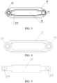
- FIG. 4 is a schematic structural diagram of a protective casing and a protective casing bracket shown in FIG. 2 ;
- FIG. 5 is a schematic structural diagram of a lens and a lens bracket shown in FIG. 2 .
- a component when a component is expressed as “being fixed to” another component, the component may be directly on the another component, or one or more intermediate components may exist between the component and the another component.
- the component When one component is expressed as “being connected to” another component, the component may be directly connected to the another component, or one or more intermediate components may exist between the component and the another component.
- Orientation or position relationships indicated by terms “upper”, “lower”, “inside”, “outside”, “top”, “bottom”, and the like used in this specification are orientation or position relationships shown based on the accompanying drawings, and are used only for ease and brevity of illustration and description, rather than indicating or implying that the mentioned apparatus or component must have a specific orientation or mush be constructed and operated in a specific orientation. Therefore, such terms should not be construed as a limitation to the present application.
- terms “first”, “second”, and “third” are only used to describe the objective and cannot be understood as indicating or implying relative importance.
- a lens assembly according to the embodiments of the present invention is applicable to various mobile terminals driven by a motor.
- the mobile terminals may have a specific structure that is commonly seen in the prior art and that enables running on the ground or flying in the air, and may include, but is not limited to, an unmanned aerial vehicle (UAV), a ship, and a robot.
- UAV unmanned aerial vehicle
- a mobile terminal may be an unmanned aerial vehicle.
- the unmanned aerial vehicle may be equipped with structures such as wings, a battery assembly, a communications module, and a landing gear, which are not specifically limited herein.
- the present invention is described by using an unmanned aerial vehicle as an example, and description of other mobile terminals is omitted.
- FIG. 1 is an overall schematic structural diagram of an unmanned aerial vehicle according to the present invention.
- FIG. 2 is a mounting structural diagram of a fuselage and a lens assembly of the unmanned aerial vehicle shown in FIG. 1 .
- FIG. 3 is a schematic structural diagram of the lens assembly shown in FIG. 2 .
- FIG. 4 is a schematic structural diagram of a protective casing and a protective casing bracket shown in FIG. 2 .
- FIG. 5 is a schematic structural diagram of a lens and a lens bracket shown in FIG. 2 .
- this embodiment provides an unmanned aerial vehicle, including a fuselage 2 , an arm 3 connected to the fuselage 2 , a power unit 4 disposed on the arm 3 , and a lens assembly 1 mounted on the fuselage 2 .
- the arm 3 may be fixedly connected to the fuselage 3 , and may be folded or unfolded relative to the fuselage 3 .
- the power unit 4 generally includes: a motor mounted at an end of the arm 3 , the end being away from the fuselage 2 ; and a propeller connected to a motor shaft of the motor. Rotation of the motor shaft drives the propeller to rotate at high speed to generate flight power of the unmanned aerial vehicle.
- the lens assembly 1 includes a lens 11 and a protective casing 12 .
- the lens 11 and the protective casing 12 are fixedly connected to the fuselage 2 separately.
- the lens 11 is sheathed in the protective casing 12 .
- a spacing exists between the protective casing 12 and the lens 11 .
- the lens assembly 1 may be fixed to the fuselage of the unmanned aerial vehicle.
- the lens assembly 1 may be fixed to a mounting plate 21 inside the fuselage 2 .
- the mounting plate 21 may be a plate-like structure extending in a horizontal direction, and a plurality of reinforcing structures may be formed on the mounting plate 21 .
- the lens assembly 1 may be fixed to the mounting plate 21 , and specifically, may be fixed and connected in such manners as screwing and clamping, as is not specifically limited herein.
- a mounting part configured to fixedly connect to the fuselage 2 is further disposed on the mounting plate 21 , whereby the lens assembly 1 is mounted on the mounting plate 21 .
- the mounting part may be a buckle, a screw hole, a connection hole or the like.
- the lens 11 may be a device used for photographing in the prior art, for example, a normal lens, a wide-angle lens, a telephoto lens, or any other type of lens.
- the lens 11 may shoot or recognize a position of an obstacle, which is not specifically limited herein.
- the position to which the lens 11 is fixed on the fuselage 2 may differ.
- the lens 11 may be fixed to a top of the fuselage 2 , or may be connected to a bottom of the fuselage 2 .
- the specific position may be set according to actual conditions.
- the lens 11 may be fixed and connected to the fuselage 2 in various manners such as clamping and screwing.
- the lens 11 may be glued to the fuselage 2 through an adhesive to simplify the connection structure and quicken the mounting.
- the protective casing 12 may have diverse structures, for example, a fixed-cross-section structure that does not change in a cross section thereof, or a variable-cross-section structure that changes in the size and shape of the cross section.
- the specific structure is not limited herein.
- the protective casing 12 may be spherical, and may cover the inside lens 11 .
- a through hole may be opened at a position that is on the protective casing 12 and that directly faces the lens 11 , so as not to prevent the lens 11 from photographing an external environment.
- the material of the protective casing 12 may also be diverse.
- the protective casing 12 may be manufactured with a material available in the prior art and processed in a common method, for example, processed by molding or forging a metal material (an iron material, a copper material, or the like), or through injection molding of plastic, as is not specifically limited herein.
- the protective casing 12 may also be fixed to the fuselage 2 , and may be fixed and connected in various manners such as gluing, clamping and riveting.
- the protective casing 12 may be detachably connected to the fuselage 2 by screws. Therefore, the protective casing 12 is conveniently replaceable in case of being damaged by a collision with an obstacle, thereby reducing repair costs.
- the size of the spacing may be a fixed value. That is, the spacings between the protective casing 12 and the lens 11 are uniform.
- the size of the spacing may be a variable value. That is, the spacings between the protective casing 12 and different positions of the lens 11 may differ.
- the specific spacings may be set according to actual conditions. If space permits, a spacing between a fixed position of the protective casing 12 and a fixed position of the lens 11 is as large as possible, so as to reduce the impact caused by the deformation of the protective casing 12 onto the lens 11 .
- the protective casing 12 undergoes the collision first and is deformed by impact.
- the impact received by the protective casing 12 will not be directly transmitted to the lens 11 to cause deformation of the lens 11 . Therefore, the lens 11 can still accurately recognize the position of the obstacle.
- the lens and the protective casing that sheathes the lens are configured.
- the lens and the protective casing are fixed to the mobile terminal separately, and a spacing exists between the protective casing and the lens.
- the protective casing receives the impact first and is deformed. Without direct connection or contact between the lens and the protective casing, a force received by the protective casing will not be directly transmitted to the lens, and the lens will not be pressed to deform by the protective casing, thereby avoiding a circumstance in which the deformation of the lens makes the mobile terminal unable to accurately recognize the obstacle.
- the lens assembly 1 further includes a protective casing bracket 13 connected to the mounting plate 21 .
- the protective casing 12 is fixed to the protective casing bracket 13 .
- a first mounting part configured to fixedly connect to the mounting plate 21 is disposed on the protective casing bracket 13 .
- the structure of the first mounting part may also be diverse.
- the first mounting part may be a connection hole, and a screw may pass through the connection hole to fit a threaded hole on the mounting plate 21 , thereby screwing the protective case bracket 13 onto the mounting plate 21 .
- the first mounting part may be a buckle, and a slot that fits the buckle may be disposed on the mounting plate 21 , so that the protective casing bracket 13 is clamped to the mounting plate 21 .
- the protective casing bracket 13 may be manufactured with a material available in the prior art and processed in a common method, for example, processed by molding or forging a metal material (an iron material, a copper material, or the like), or through injection molding of plastic, as is not specifically limited herein.
- a metal material an iron material, a copper material, or the like
- the protective casing bracket 13 may be a lightweight metal material, thereby reducing weight of the mobile terminal and increasing firmness of connection.
- a shape of the protective casing bracket 13 may be diverse.
- the protective casing bracket 13 may be an extrusion profile or framework structure.
- the protective casing 12 may be fixedly connected to the protective casing bracket 13 in different ways such as riveting and clamping.
- the protective casing 12 may be screwed onto the protective casing bracket 13 , thereby simplifying the structure and being easy to implement.
- the method of fixing and connection between the protective casing 12 and the protective casing bracket 13 may be the same as or different from the method of fixing and connection between the protective casing bracket 13 and the mounting plate 21 , as is not specifically limited herein.
- the protective casing bracket 13 may be not in contact with the lens 11 . Therefore, the impact received by the protective casing 12 is prevented from being transmitted to the lens 11 through the protective casing bracket 13 to affect the recognition of the obstacle by the lens 11 . Moreover, the impact received by the protective casing 12 passes through the protective casing bracket 13 before being transmitted to the fuselage 2 . Therefore, the impact received by the fuselage 2 is reduced, and the impact on the lens 11 is further reduced.
- the lens assembly 1 further includes a lens bracket 14 connected to the mounting plate 21 .
- the lens 11 is fixed to the lens bracket 14 .
- a second mounting part configured to fixedly connect to the mounting plate 21 is disposed on the lens bracket 14 .
- the structure of the second mounting part may also be diverse.
- the second mounting part may be a connection hole, and a screw may pass through the connection hole to fit a threaded hole on the mounting plate 21 , thereby screwing the lens bracket 14 onto the mounting plate 21 .
- the second mounting part may be a buckle, and a slot that fits the buckle may be disposed on the mounting plate 21 , so that the lens bracket 14 is clamped to the mounting plate 21 .
- the plurality of second mounting parts may be disposed on the lens bracket 14 at intervals to enhance the effect of fixing the lens bracket 14 to the mounting plate 21 .
- the lens bracket 14 may be manufactured with a material available in the prior art and processed in a common method, for example, processed by molding or forging a metal material (an iron material, a copper material, or the like), or through injection molding of plastic, as is not specifically limited herein.
- a metal material an iron material, a copper material, or the like
- the lens bracket 14 may be a lightweight metal material, thereby reducing weight of the mobile terminal and increasing firmness of connection.
- a shape of the lens bracket 14 may be diverse.
- the lens bracket 14 may be an extrusion profile or framework structure.
- the lens 11 may be fixed and connected to the lens bracket 14 in various manners such as screwing and clamping.
- the lens 11 may be glued to the lens bracket 14 to facilitate and quicken mounting.
- the method of fixing and connection between the lens 11 and the lens bracket 14 may be the same as or different from the method of fixing and connection between the lens bracket 14 and the mounting plate 21 , as is not specifically limited herein.
- the lens assembly 1 may have one lens 11 and one protective casing 12 . Further, the lens assembly 1 may also have one lens bracket 14 and one protective casing bracket 13 . The lens 11 may be fixed to the mounting plate 21 through the lens bracket 14 , and the protective casing 12 may be fixed to the mounting plate 21 through the protective casing bracket 13 . In addition, a spacing exists between the lens 11 and the protective casing 12 to reduce the effect of the impact on the lens 11 .
- each lens 11 may be sheathed in a protective casing 12 so that each lens 11 is protected.
- the number of lens brackets 14 may be the same as the number of lenses 11 . That is, each lens 11 may be fixed to the mobile terminal body 2 through a separate lens bracket 14 .
- the number of the lens bracket 14 is 1, and a plurality of lenses 11 are all fixed to the lens bracket 14 at intervals.
- the number of protective casing brackets 13 may be the same as the number of protective casings 12 . That is, each protective casing 12 may be fixed to the mounting plate 21 through a separate protective casing bracket 13 .
- the number of protective casing brackets 13 may also be one, and a plurality of protective casings 12 may be fixed to the protective casing bracket 13 at intervals.
- the lens 11 includes a first lens 111 and a second lens 112 .
- the protective casing 12 includes a first protective casing 121 and a second protective casing 122 .
- the first protective casing 121 sheathes the first lens 111
- the second protective casing 122 sheathes the second lens 112 .
- the number of the lens bracket 14 is one, and the first lens 111 and the second lens 112 are fixed to two ends of the lens bracket 14 respectively.
- the number of the protective casing bracket 13 is one, and the first protective casing 121 and the second protective casing 122 are fixed to two ends of the protective casing bracket 13 respectively.
- the lens bracket 14 takes on a plate shape extending along a first preset direction.
- the first lens 111 and the second lens 112 are fixed to two ends of the lens bracket 14 respectively along the first preset direction.
- the protective casing bracket 13 is also a rectangular framework shape extending along a second preset direction.
- the first protective casing 121 and the second protective casing 122 are fixed to two ends of the protective casing bracket 13 respectively along the second preset direction.
- the first preset direction may be a linear direction or a curved direction, as is not specifically limited herein.
- the first preset direction may be a horizontal direction, a vertical direction, or the like.
- the second preset direction may be a linear direction or a curved direction, as is not specifically limited herein.
- the second preset direction may be a horizontal direction, a vertical direction, or the like.
- the second preset direction may be the same as the first preset direction, thereby simplifying the structure of the protective casing bracket 13 and the lens bracket 14 .
- the protective casing bracket 13 sheathes the lens bracket 14 , and a spacing exists between the protective casing bracket 13 and the lens bracket 14 .
- the protective casing bracket 13 may be an arc-shaped structure, and may define an accommodation cavity with an opening opened on one side.
- the lens bracket 14 may be located in the accommodation cavity.
- An edge of the lens bracket 14 is not in contact with the protective casing bracket 13 , thereby forming a spacing between the protective casing bracket 13 and the lens bracket 14 . That is, the protective casing bracket 13 and the lens bracket 14 are not in contact with each other, so that the deformed protective casing 12 will not press the lens 11 .
- the impact received by the protective casing 12 passes through the protective casing bracket 13 before being transmitted to the mobile terminal body 2 , and then passes through the lens bracket 14 before being transmitted to the lens 11 . Therefore, the lens 11 is hardly affected by the impact, and recognition results are more accurate.
- the size of the spacing may be a fixed value. That is, the spacings between the protective casing bracket 13 and the lens bracket 14 may be uniform.
- the size of the spacing may be a variable value. That is, the spacings between the protective casing bracket 13 and different positions of the lens bracket 14 may differ.
- the specific spacings may be set according to actual conditions. If space permits, the spacing between the protective casing bracket 13 and the lens bracket 14 is as large as possible, so as to reduce the impact transmitted between the protective casing bracket 13 and the lens bracket 14 .
- a mounting hole 131 is disposed on the protective casing bracket 13 , and the lens bracket 14 is accommodated in the mounting hole 131 .
- the protective casing bracket 13 may be a hollow annular structure or a rectangular framework structure.
- the lens bracket 14 may be located inside the protective casing bracket 13 , thereby reducing the required mounting space and enhancing the strength of the protective casing bracket 13 .
- the first lens 111 and the second lens 112 are symmetrically arranged with respect to the same plane, and the first protective casing 121 and the second protective casing 122 are symmetrically arranged with respect to the same plane, so as to enhance structural stability.
- the plane may be a horizontal plane or a vertical plane in the case of horizontal arrangement, as is not specifically limited herein.
- the lens bracket 14 may be symmetric with respect to such plane, and the protective casing bracket 13 may also be symmetric with respect to such plane, to support the strength.
- the protective casing bracket 13 may be equipped with a reinforcing rib 132 .
- the reinforcing rib 132 may be formed by sheet metal bending or stamping.
- the reinforcing rib 132 may be formed by bending the edge of the protective casing bracket 13 to enhance the strength of the protective casing bracket 13 .
- the protective casing 12 is cylindrical, and the length of the protective casing 12 along an axial direction is greater than the length of the lens 11 along the same axial direction. Therefore, the protective casing 12 can protrude from a surface of the lens 11 to accomplish a better protection effect.
- the protective casing 12 in the lens assembly 1 can protect the lens 11 from being damaged.
- the protective casing 12 and the lens 11 are both mounted on the fuselage 2 and spaced apart from each other by a spacing, the impact received by the protective casing 12 will not affect the lens 11 . Therefore, the lens 11 will not be impacted or pressed to deform, and the obstacle detection function of the mobile terminal will not be affected.
- the lens assembly provided in this embodiment includes a lens and a protective casing that sheathes the lens.
- the lens and the protective casing are fixed to the fuselage of the unmanned aerial vehicle separately, and a spacing exists between the protective casing and the lens.
- the protective casing receives the impact first and is deformed. Without direct connection or contact between the lens and the protective casing, a force received by the protective casing will not be directly transmitted to the lens, and the lens will not be pressed to deform by the protective casing, thereby avoiding a circumstance in which the deformation of the lens makes the mobile terminal unable to accurately recognize the obstacle.
Landscapes
- Physics & Mathematics (AREA)
- General Physics & Mathematics (AREA)
- Optics & Photonics (AREA)
- Studio Devices (AREA)
- Engineering & Computer Science (AREA)
- Aviation & Aerospace Engineering (AREA)
Abstract
Description
-
- the protective casing includes a first protective casing covering the first lens and a second protective casing covering the second lens, the first protective casing and the second protective casing being fixed to two ends of the lens bracket respectively.
-
- 1: Lens assembly;
- 11: Lens;
- 111: First lens;
- 112: Second lens;
- 12: Protective casing;
- 121: First protective casing;
- 122: Second protective casing;
- 13: Protective casing bracket;
- 131: Mounting hole;
- 132: Reinforcing rib;
- 14: Lens bracket;
- 2: Fuselage of an unmanned aerial vehicle; and
- 21: Mounting plate.
Claims (16)
Applications Claiming Priority (3)
| Application Number | Priority Date | Filing Date | Title |
|---|---|---|---|
| CN201820120515.9 | 2018-01-24 | ||
| CN201820120515.9U CN207926714U (en) | 2018-01-24 | 2018-01-24 | lens assembly and mobile terminal |
| PCT/CN2018/113589 WO2019144673A1 (en) | 2018-01-24 | 2018-11-02 | Lens assembly and mobile terminal |
Related Parent Applications (1)
| Application Number | Title | Priority Date | Filing Date |
|---|---|---|---|
| PCT/CN2018/113589 Continuation WO2019144673A1 (en) | 2018-01-24 | 2018-11-02 | Lens assembly and mobile terminal |
Publications (2)
| Publication Number | Publication Date |
|---|---|
| US20200355886A1 US20200355886A1 (en) | 2020-11-12 |
| US12181727B2 true US12181727B2 (en) | 2024-12-31 |
Family
ID=63605192
Family Applications (1)
| Application Number | Title | Priority Date | Filing Date |
|---|---|---|---|
| US16/938,181 Active 2041-12-29 US12181727B2 (en) | 2018-01-24 | 2020-07-24 | Lens assembly and mobile terminal |
Country Status (3)
| Country | Link |
|---|---|
| US (1) | US12181727B2 (en) |
| CN (1) | CN207926714U (en) |
| WO (1) | WO2019144673A1 (en) |
Families Citing this family (3)
| Publication number | Priority date | Publication date | Assignee | Title |
|---|---|---|---|---|
| CN207926714U (en) * | 2018-01-24 | 2018-09-28 | 深圳市道通智能航空技术有限公司 | lens assembly and mobile terminal |
| KR102644729B1 (en) * | 2021-07-01 | 2024-03-12 | 주식회사 공간정보 | unmaned air vehicle for multi-using |
| CN116280300B (en) * | 2023-01-09 | 2025-08-01 | 南通嗨森无人机科技有限公司 | Self-adaptive unmanned aerial vehicle geographic information mapping device |
Citations (15)
| Publication number | Priority date | Publication date | Assignee | Title |
|---|---|---|---|---|
| US4558927A (en) * | 1982-08-21 | 1985-12-17 | Nippon Kogaku K.K. | Zoom lens assembly |
| US5231435A (en) * | 1991-07-12 | 1993-07-27 | Blakely Bruce W | Aerial camera mounting apparatus |
| US6707619B1 (en) * | 1998-11-20 | 2004-03-16 | Sony Corporation | Video camera device |
| US20080068727A1 (en) * | 2006-09-18 | 2008-03-20 | Gary Peter Widdowson | Optical zoom mechanism |
| JP2008102354A (en) | 2006-10-19 | 2008-05-01 | Fujifilm Corp | Photographing device |
| US20090097138A1 (en) * | 2005-12-02 | 2009-04-16 | Naoto Yumiki | Interchangeable lens barrel, program rewriting system for interchangeable lens barrel |
| CN201233464Y (en) | 2008-07-14 | 2009-05-06 | 华晶科技股份有限公司 | Lens module |
| US7963707B2 (en) * | 2009-03-31 | 2011-06-21 | Powertech Electronics | Dome type security camera structure with reinforced waterproofing function |
| US20120262708A1 (en) * | 2009-11-25 | 2012-10-18 | Cyberhawk Innovations Limited | Unmanned aerial vehicle |
| US8553142B2 (en) * | 2008-10-30 | 2013-10-08 | Lite-On Electronics (Guangzhou) Limited | Camera lens module and manufacturing method thereof |
| CN104267564A (en) | 2014-09-22 | 2015-01-07 | 苏州佳世达光电有限公司 | Lens module and projection device |
| US9140890B1 (en) * | 2013-06-27 | 2015-09-22 | Thomas Eugene Wilhelm | Adjustable magnifying glass mounting system |
| US9464938B2 (en) * | 2014-02-06 | 2016-10-11 | The Boeing Company | Systems and methods for measuring polarization of light in images |
| CN107458616A (en) | 2017-07-25 | 2017-12-12 | 芜湖超源力工业设计有限公司 | A kind of unmanned plane with high-definition camera defencive function |
| CN207926714U (en) | 2018-01-24 | 2018-09-28 | 深圳市道通智能航空技术有限公司 | lens assembly and mobile terminal |
-
2018
- 2018-01-24 CN CN201820120515.9U patent/CN207926714U/en active Active
- 2018-11-02 WO PCT/CN2018/113589 patent/WO2019144673A1/en not_active Ceased
-
2020
- 2020-07-24 US US16/938,181 patent/US12181727B2/en active Active
Patent Citations (15)
| Publication number | Priority date | Publication date | Assignee | Title |
|---|---|---|---|---|
| US4558927A (en) * | 1982-08-21 | 1985-12-17 | Nippon Kogaku K.K. | Zoom lens assembly |
| US5231435A (en) * | 1991-07-12 | 1993-07-27 | Blakely Bruce W | Aerial camera mounting apparatus |
| US6707619B1 (en) * | 1998-11-20 | 2004-03-16 | Sony Corporation | Video camera device |
| US20090097138A1 (en) * | 2005-12-02 | 2009-04-16 | Naoto Yumiki | Interchangeable lens barrel, program rewriting system for interchangeable lens barrel |
| US20080068727A1 (en) * | 2006-09-18 | 2008-03-20 | Gary Peter Widdowson | Optical zoom mechanism |
| JP2008102354A (en) | 2006-10-19 | 2008-05-01 | Fujifilm Corp | Photographing device |
| CN201233464Y (en) | 2008-07-14 | 2009-05-06 | 华晶科技股份有限公司 | Lens module |
| US8553142B2 (en) * | 2008-10-30 | 2013-10-08 | Lite-On Electronics (Guangzhou) Limited | Camera lens module and manufacturing method thereof |
| US7963707B2 (en) * | 2009-03-31 | 2011-06-21 | Powertech Electronics | Dome type security camera structure with reinforced waterproofing function |
| US20120262708A1 (en) * | 2009-11-25 | 2012-10-18 | Cyberhawk Innovations Limited | Unmanned aerial vehicle |
| US9140890B1 (en) * | 2013-06-27 | 2015-09-22 | Thomas Eugene Wilhelm | Adjustable magnifying glass mounting system |
| US9464938B2 (en) * | 2014-02-06 | 2016-10-11 | The Boeing Company | Systems and methods for measuring polarization of light in images |
| CN104267564A (en) | 2014-09-22 | 2015-01-07 | 苏州佳世达光电有限公司 | Lens module and projection device |
| CN107458616A (en) | 2017-07-25 | 2017-12-12 | 芜湖超源力工业设计有限公司 | A kind of unmanned plane with high-definition camera defencive function |
| CN207926714U (en) | 2018-01-24 | 2018-09-28 | 深圳市道通智能航空技术有限公司 | lens assembly and mobile terminal |
Non-Patent Citations (1)
| Title |
|---|
| The International Search Report mailed Jan. 24, 2019; PCT/CN2018/113589. |
Also Published As
| Publication number | Publication date |
|---|---|
| WO2019144673A1 (en) | 2019-08-01 |
| US20200355886A1 (en) | 2020-11-12 |
| CN207926714U (en) | 2018-09-28 |
Similar Documents
| Publication | Publication Date | Title |
|---|---|---|
| US12181727B2 (en) | Lens assembly and mobile terminal | |
| US10967970B2 (en) | Durable modular unmanned aerial vehicle | |
| US12492021B2 (en) | Modular unmanned aerial vehicle airframe with structurally integrated yoke and payload assembly | |
| EP3765360B1 (en) | Clip-on propeller mount | |
| US10486828B2 (en) | Unmanned aerial vehicle | |
| US10780975B2 (en) | Clip-on propeller mount | |
| KR102427350B1 (en) | Camera module and camera for vehicle | |
| US11066155B2 (en) | Unmanned aerial vehicle | |
| CN113911326B (en) | Unmanned aerial vehicles | |
| US10194061B2 (en) | Pan-tilt-zoom camera and unmanned aerial vehicle | |
| CN109383739B (en) | Horn and unmanned aerial vehicle | |
| US20190382106A1 (en) | Folding concentrically mounted propeller blades for drag reduction | |
| US20190248502A1 (en) | Battery compartment | |
| US20220324565A1 (en) | Unmanned aerial vehicle | |
| CN108791805A (en) | Unmanned vehicle and its horn component and rotating shaft mechanism | |
| US20190016460A1 (en) | Unmanned aerial vehicle | |
| US20220153404A1 (en) | Methods and unmanned aerial vehicles for longer duration flights | |
| CN118358751A (en) | Tilt rotor unmanned aerial vehicle and wing subassembly thereof | |
| US11254444B2 (en) | Gimbal, photographing apparatus having same, and unmanned aerial vehicle | |
| WO2020135796A1 (en) | Fan assembly, inertial measurement assembly, and unmanned aerial vehicle | |
| CN108609156A (en) | Unmanned vehicle and its frame assembly | |
| US12473104B2 (en) | Unmanned aerial device | |
| CN107458616A (en) | A kind of unmanned plane with high-definition camera defencive function | |
| CN217416130U (en) | Camera and unmanned aerial vehicle | |
| CN209938925U (en) | A horn for unmanned aerial vehicle |
Legal Events
| Date | Code | Title | Description |
|---|---|---|---|
| FEPP | Fee payment procedure |
Free format text: ENTITY STATUS SET TO UNDISCOUNTED (ORIGINAL EVENT CODE: BIG.); ENTITY STATUS OF PATENT OWNER: LARGE ENTITY |
|
| STPP | Information on status: patent application and granting procedure in general |
Free format text: DOCKETED NEW CASE - READY FOR EXAMINATION |
|
| STPP | Information on status: patent application and granting procedure in general |
Free format text: NON FINAL ACTION MAILED |
|
| STPP | Information on status: patent application and granting procedure in general |
Free format text: RESPONSE TO NON-FINAL OFFICE ACTION ENTERED AND FORWARDED TO EXAMINER |
|
| STPP | Information on status: patent application and granting procedure in general |
Free format text: FINAL REJECTION MAILED |
|
| STPP | Information on status: patent application and granting procedure in general |
Free format text: RESPONSE AFTER FINAL ACTION FORWARDED TO EXAMINER |
|
| STPP | Information on status: patent application and granting procedure in general |
Free format text: NOTICE OF ALLOWANCE MAILED -- APPLICATION RECEIVED IN OFFICE OF PUBLICATIONS |
|
| ZAAB | Notice of allowance mailed |
Free format text: ORIGINAL CODE: MN/=. |
|
| STPP | Information on status: patent application and granting procedure in general |
Free format text: AWAITING TC RESP., ISSUE FEE NOT PAID |
|
| STPP | Information on status: patent application and granting procedure in general |
Free format text: NOTICE OF ALLOWANCE MAILED -- APPLICATION RECEIVED IN OFFICE OF PUBLICATIONS |
|
| STCB | Information on status: application discontinuation |
Free format text: ABANDONED -- FAILURE TO PAY ISSUE FEE |
|
| STPP | Information on status: patent application and granting procedure in general |
Free format text: PUBLICATIONS -- ISSUE FEE PAYMENT RECEIVED |
|
| STPP | Information on status: patent application and granting procedure in general |
Free format text: PUBLICATIONS -- ISSUE FEE PAYMENT VERIFIED |
|
| STCF | Information on status: patent grant |
Free format text: PATENTED CASE |