US12181046B2 - Variable stiffness function through a check valve in a hydraulic - Google Patents
Variable stiffness function through a check valve in a hydraulic Download PDFInfo
- Publication number
- US12181046B2 US12181046B2 US18/554,592 US202118554592A US12181046B2 US 12181046 B2 US12181046 B2 US 12181046B2 US 202118554592 A US202118554592 A US 202118554592A US 12181046 B2 US12181046 B2 US 12181046B2
- Authority
- US
- United States
- Prior art keywords
- check valve
- vent
- reservoir
- retainer
- openings
- Prior art date
- Legal status (The legal status is an assumption and is not a legal conclusion. Google has not performed a legal analysis and makes no representation as to the accuracy of the status listed.)
- Active
Links
Images


Classifications
-
- F—MECHANICAL ENGINEERING; LIGHTING; HEATING; WEAPONS; BLASTING
- F16—ENGINEERING ELEMENTS AND UNITS; GENERAL MEASURES FOR PRODUCING AND MAINTAINING EFFECTIVE FUNCTIONING OF MACHINES OR INSTALLATIONS; THERMAL INSULATION IN GENERAL
- F16H—GEARING
- F16H7/00—Gearings for conveying rotary motion by endless flexible members
- F16H7/08—Means for varying tension of belts, ropes or chains
- F16H7/0848—Means for varying tension of belts, ropes or chains with means for impeding reverse motion
-
- F—MECHANICAL ENGINEERING; LIGHTING; HEATING; WEAPONS; BLASTING
- F01—MACHINES OR ENGINES IN GENERAL; ENGINE PLANTS IN GENERAL; STEAM ENGINES
- F01L—CYCLICALLY OPERATING VALVES FOR MACHINES OR ENGINES
- F01L1/00—Valve-gear or valve arrangements, e.g. lift-valve gear
- F01L1/02—Valve drive
- F01L1/022—Chain drive
-
- F—MECHANICAL ENGINEERING; LIGHTING; HEATING; WEAPONS; BLASTING
- F01—MACHINES OR ENGINES IN GENERAL; ENGINE PLANTS IN GENERAL; STEAM ENGINES
- F01L—CYCLICALLY OPERATING VALVES FOR MACHINES OR ENGINES
- F01L1/00—Valve-gear or valve arrangements, e.g. lift-valve gear
- F01L1/02—Valve drive
- F01L1/024—Belt drive
-
- F—MECHANICAL ENGINEERING; LIGHTING; HEATING; WEAPONS; BLASTING
- F16—ENGINEERING ELEMENTS AND UNITS; GENERAL MEASURES FOR PRODUCING AND MAINTAINING EFFECTIVE FUNCTIONING OF MACHINES OR INSTALLATIONS; THERMAL INSULATION IN GENERAL
- F16H—GEARING
- F16H7/00—Gearings for conveying rotary motion by endless flexible members
- F16H7/08—Means for varying tension of belts, ropes or chains
- F16H7/0829—Means for varying tension of belts, ropes or chains with vibration damping means
- F16H7/0836—Means for varying tension of belts, ropes or chains with vibration damping means of the fluid and restriction type, e.g. dashpot
-
- F—MECHANICAL ENGINEERING; LIGHTING; HEATING; WEAPONS; BLASTING
- F16—ENGINEERING ELEMENTS AND UNITS; GENERAL MEASURES FOR PRODUCING AND MAINTAINING EFFECTIVE FUNCTIONING OF MACHINES OR INSTALLATIONS; THERMAL INSULATION IN GENERAL
- F16K—VALVES; TAPS; COCKS; ACTUATING-FLOATS; DEVICES FOR VENTING OR AERATING
- F16K15/00—Check valves
- F16K15/02—Check valves with guided rigid valve members
- F16K15/04—Check valves with guided rigid valve members shaped as balls
- F16K15/044—Check valves with guided rigid valve members shaped as balls spring-loaded
-
- F—MECHANICAL ENGINEERING; LIGHTING; HEATING; WEAPONS; BLASTING
- F16—ENGINEERING ELEMENTS AND UNITS; GENERAL MEASURES FOR PRODUCING AND MAINTAINING EFFECTIVE FUNCTIONING OF MACHINES OR INSTALLATIONS; THERMAL INSULATION IN GENERAL
- F16H—GEARING
- F16H7/00—Gearings for conveying rotary motion by endless flexible members
- F16H7/08—Means for varying tension of belts, ropes or chains
- F16H2007/0802—Actuators for final output members
- F16H2007/0806—Compression coil springs
-
- F—MECHANICAL ENGINEERING; LIGHTING; HEATING; WEAPONS; BLASTING
- F16—ENGINEERING ELEMENTS AND UNITS; GENERAL MEASURES FOR PRODUCING AND MAINTAINING EFFECTIVE FUNCTIONING OF MACHINES OR INSTALLATIONS; THERMAL INSULATION IN GENERAL
- F16H—GEARING
- F16H7/00—Gearings for conveying rotary motion by endless flexible members
- F16H7/08—Means for varying tension of belts, ropes or chains
- F16H2007/0802—Actuators for final output members
- F16H2007/0812—Fluid pressure
-
- F—MECHANICAL ENGINEERING; LIGHTING; HEATING; WEAPONS; BLASTING
- F16—ENGINEERING ELEMENTS AND UNITS; GENERAL MEASURES FOR PRODUCING AND MAINTAINING EFFECTIVE FUNCTIONING OF MACHINES OR INSTALLATIONS; THERMAL INSULATION IN GENERAL
- F16H—GEARING
- F16H7/00—Gearings for conveying rotary motion by endless flexible members
- F16H7/08—Means for varying tension of belts, ropes or chains
- F16H7/0848—Means for varying tension of belts, ropes or chains with means for impeding reverse motion
- F16H2007/0859—Check valves
Definitions
- the present invention relates to hydraulic tensioners, and more specifically to a variable stiffness function through application of a check valve with a vent in the hydraulic tensioner.
- Internal reservoir type chain tensioner use hydraulic stiffness adjustment by restricting oil leak rate with the some components.
- the tensioner stiffness changes significantly with temperature and oil viscosity. Under low temperatures, the hydraulic tensioner generates excessive force by the high viscosity of the oil. Under high temperatures, the tensioner generates insufficient force to control the engine timing system due to the low viscosity of the oil.
- FIG. 1 shows a conventional reservoir type hydraulic tensioner 10 .
- a housing 2 has a closed end bore 3 which receives a hollow piston 4 .
- the hollow piston 4 is received within the closed end bore 3 of the housing 2 .
- the hollow piston 4 has a centerline or center plane C-C.
- a reservoir hole 40 that allows the entry and exit of fluid from an internal reservoir 41 formed within the hollow interior 4 c of the piston 4 .
- Also present within the closed end bore 3 is a check valve assembly 20 , a washer 43 , a high pressure chamber 8 formed between the bore 3 , the internal interior 4 c of the piston 4 , and the check valve assembly 20 .
- the check valve assembly 20 includes a check valve seat 25 , a spring 26 , a ball 27 and a retainer 28 .
- the washer 43 has a single central hole 44 to the internal reservoir 41 .
- the single central hole 44 is aligned with a hole 29 in the check valve seat 25 .
- the washer 43 and check valve vent 29 utilize a significant amount of room within the hollow piston 4 .
- a vent groove 45 is present on an outside of the check valve seat 25 and is present between the check valve seat 25 and the washer 43 .
- FIG. 2 shows another conventional reservoir type hydraulic tensioner 50 .
- a housing 2 has a closed end bore 3 which receives a hollow piston 4 .
- an oil inlet feed 5 that is in fluid communication with an oil supply.
- the hollow piston 4 is received within the closed end bore 3 of the housing 2 .
- the hollow piston 4 has a centerline or center plane C-C.
- a reservoir hole 40 that allows the entry and exit of fluid from an internal reservoir 41 formed within the hollow interior 4 c of the piston 4 .
- the washer 83 Due to the size and shape of the washer 83 , the washer 83 can flip or tilt during tensioner operation and has to be fixed with in the inner diameter of the hollow piston 4 . Therefore, the outer diameter of the washer 83 and the inner diameter of the hollow piston 4 has to be manufactured with high precision.
- the check valve assembly improves the range of variation of the tensioner stiffness by controlling venting and thus the oil flow rate of oil through the check valve assembly of the hydraulic tensioner.
- the check valve vent washer has an outer circumference with a plurality of spaced apart legs and a plurality of openings; and an inner circumference in fluid communication with the outer circumference through the plurality of openings, the inner circumference comprising: a concentric interior well connecting the plurality of openings to a vent reservoir, a central ring defining a central hole in communication with the internal reservoir, the central ring comprising a vent groove connecting the vent reservoir to the central hole.
- FIG. 2 shows another conventional reservoir type hydraulic tensioner with a check valve assembly.
- FIG. 4 shows a schematic of a hydraulic tensioner of an embodiment of the present invention.
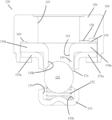
- FIG. 6 shows a top view of the check valve vent.
- FIG. 7 shows fluid flow associated with the check valve vent.
- FIG. 4 - 7 show a hydraulic tensioner and associated components of an embodiment of the present invention.
- the hydraulic tensioner 100 can be used for an endless loop, flexible, power transmission member for an internal combustion engine of a motor vehicle, such as a chain or belt.
- the power transmission member encircles a drive sprocket driven by a drive shaft, such as a crank shaft of the engine, and the at least one driven sprocket supported from a driven shaft, such as a cam shaft of the engine.
- the hydraulic tensioner is mounted to an engine block of an internal combustion engine (not shown) via a mounting plate 102 .
- the mounting plate 102 is secured to the engine block (not shown) via bolts or screws received in mounting plate holes 101 .
- the mounting plate 102 is coupled to or formed in part with a tensioner housing 103 .
- the tensioner housing 103 has a closed end multi-staged internal bore 103 a . Between the closed end 121 of the bore 103 a and the open end 122 of the bore 103 a is an inlet portion 123 of the bore 103 a which has a diameter d 1 , which is greater than the diameter d 2 of the bore 103 a at the closed end 121 and the open end 122 of the bore.
- An oil inlet 105 is present in the inlet portion 123 of the bore 13 a and is in fluid communication with a fluid supply (not shown).
- a hollow piston 104 is slidably received within the bore 103 a of the housing 103 .
- the hollow piston 104 has a body with a first end 104 a , a second end 104 b , and a length L between the first end 104 a and the second end 104 b .
- the first end 104 a of the hollow piston 4 is in contact with a tensioner body, guide or endless loop, flexible, power transmission member for an internal combustion engine.
- the second end 104 b of the hollow piston 104 is received within the bore 103 a of the tensioner housing 103 .
- the hollow piston 4 has an internal bore 104 c .
- the internal bore 104 c of the hollow piston 4 has a first diameter D 1 and a second diameter D 2 .
- the first diameter D 1 is preferably smaller than the second diameter D 2 .
- an inlet 104 d which is in communication with the oil inlet 105 .
- a check valve assembly 120 is received within the second diameter D 2 of the internal bore 104 c of the piston 104 , dividing the internal bore 104 c into an internal reservoir 106 and a high pressure chamber 108 .
- the internal reservoir 106 is formed between the first diameter D 1 of the internal bore 104 c and the check valve assembly 120 .
- the high pressure chamber 108 is formed between the check valve assembly 120 , the second diameter D 2 of the internal bore 104 c of the piston 104 , the second end 104 b of the piston 104 , and the closed end 121 of the bore 103 a of the housing 103 .
- a spring 107 is also preferably present within the high pressure chamber 108 , with a first end 107 a of the spring 107 biased against the check valve assembly 120 and the second end 107 b of the spring 107 biased against the closed end 121 of the bore 103 a of the housing 103 , biasing the check valve assembly 120 , and thus the piston 104 outwards and away from the closed end 121 of the bore 103 a of the tensioner housing 103 .
- the check valve assembly 120 includes a retainer 153 , a valve seat 154 , a check valve spring 152 , a moveable member 151 , and a check valve vent washer 156 .
- the retainer 153 is U-shaped and defines a cavity 175 which receives a moveable member 151 , a spring 152 and a valve seat 154 . Between the bottom 153 b and the flanges 153 a of the U-shaped retainer 153 is at least one retainer opening 176 . Also partially received within the retainer 153 is a valve seat 154 . The moveable member 151 , shown as being ball shaped, and the check valve spring 152 are held between the valve seat 154 and the retainer 153 .
- the valve seat 154 includes a seat opening 154 b , against which the ball 151 is biased by the check valve spring 152 to bias the check valve toward the closed position shown in FIG. 5 .
- the valve seat 154 is includes flanges 154 a which extend axially outwards.
- the valve seat 154 nests within the cavity 175 of the retainer 153 , such that the flanges 153 a of the U-shaped retainer 153 are adjacent the flanges 154 a of the valve seat 154 .
- a cup-shaped check valve vent washer 156 receives the flanges 154 a of the valve seat 154 and the flanges 153 a of the U-shaped retainer 153 within an inner circumference 162 within the cup.
- the check valve vent washer 156 has a radially symmetric profile with an outer circumference 161 and an inner circumference 162 with an interior well 160 surrounding a ring 177 with a central hole 157 .
- the outer circumference 161 of the cup-shaped check valve vent washer 156 has a plurality of legs 163 , 164 , 165 , 166 , 167 , 168 and leg openings 169 , 170 , 171 , 172 , 173 , 174 defining the inner circumference 162 of the cup.
- the outer circumference 161 preferably includes a first long leg 163 , opposite a second long leg 164 , with at least one short leg 165 , 166 , 167 , 168 between the first long leg 163 and the second long leg 164 separated by openings 169 , 171 , 174 , 172 on either side.
- the check valve vent washer 156 has a first long leg 163 , a first opening 169 , a first short leg 165 , a second opening 170 , a second short leg 166 , a third opening 171 , a second long leg 164 diametrically opposite the first long leg 163 , a fourth opening 172 , a third short leg 167 , a fifth opening 173 , a fourth short leg 161 and a sixth opening 174 .
- the second opening 170 and fifth opening 173 could be removed and the first short leg 165 and second short leg 166 could be combined to form a single leg with a first opening 169 on one side and the third opening 171 on the other side.
- the fourth short leg 168 and the third short leg 167 could be combined to form a single leg with the sixth opening 174 and the fourth opening 172 on either side.
- the legs 163 , 164 , 165 , 166 , 167 , 168 of the outer circumference 161 of the check valve vent washer 156 allows a backflow path of hydraulic fluid, which is typically oil, into the hydraulic fluid reservoir 106 .
- the openings 169 , 170 , 171 , 172 , 173 , 174 between the legs 163 , 164 , 165 , 166 , 167 , 168 extend from an outer surface of the outer circumference 161 to the inner circumference 162 and towards the inner central hole 157 .
- the openings 169 , 170 , 171 , 172 , 173 , 174 are arched openings having a concave shape, but any shape can be used.
- the openings 169 , 170 , 171 , 172 , 173 , 174 are not aligned with the vent reservoir 159 , such that the openings 169 , 170 , 171 , 172 , 173 , 174 do not extend radially into vent reservoir 159 .
- the check valve vent legs 163 , 164 , 165 , 166 , 167 , 168 are preferably of a substantially uniform thickness and is preferably formed from a single piece.
- pressurized fluid flows into the check valve assembly 120 through the seat opening 155 by pushing the ball 151 away from the valve seat 156 , against the bias of the check valve spring 152 , such that the check valve assembly 120 is moved to an open position.
- Pressurized fluid flows out of the check valve assembly 120 through the at least one retainer opening 176 .
Landscapes
- Engineering & Computer Science (AREA)
- General Engineering & Computer Science (AREA)
- Mechanical Engineering (AREA)
- Devices For Conveying Motion By Means Of Endless Flexible Members (AREA)
Abstract
Description
Claims (9)
Applications Claiming Priority (1)
| Application Number | Priority Date | Filing Date | Title |
|---|---|---|---|
| PCT/US2021/027090 WO2022220802A1 (en) | 2021-04-13 | 2021-04-13 | Variable stiffness function through a check valve in a hydraulic tensioner |
Publications (2)
| Publication Number | Publication Date |
|---|---|
| US20240191783A1 US20240191783A1 (en) | 2024-06-13 |
| US12181046B2 true US12181046B2 (en) | 2024-12-31 |
Family
ID=83639463
Family Applications (1)
| Application Number | Title | Priority Date | Filing Date |
|---|---|---|---|
| US18/554,592 Active US12181046B2 (en) | 2021-04-13 | 2021-04-13 | Variable stiffness function through a check valve in a hydraulic |
Country Status (4)
| Country | Link |
|---|---|
| US (1) | US12181046B2 (en) |
| CN (1) | CN117120748A (en) |
| DE (1) | DE112021007054T5 (en) |
| WO (1) | WO2022220802A1 (en) |
Citations (154)
| Publication number | Priority date | Publication date | Assignee | Title |
|---|---|---|---|---|
| US976010A (en) | 1909-11-03 | 1910-11-15 | John C Thompson | Valve. |
| US979811A (en) | 1909-04-30 | 1910-12-27 | Harrison Safety Boiler Works | Valve. |
| US1613145A (en) | 1923-07-03 | 1927-01-04 | Humphrey Gas Pump Company | Valve construction |
| US1682602A (en) | 1924-04-05 | 1928-08-28 | Clarence A Dawley | Flow meter |
| US1915694A (en) | 1927-10-27 | 1933-06-27 | Ira H Reindel | Valve silencing construction |
| US2167721A (en) | 1930-11-22 | 1939-08-01 | Bendix Brake Co | Brake |
| US2273737A (en) | 1939-12-30 | 1942-02-17 | Mahlon C Snyder | Vent device for gasoline containers and the like |
| US2308876A (en) | 1940-09-28 | 1943-01-19 | Axelson Mfg Co | Valve construction |
| US2767733A (en) | 1951-12-26 | 1956-10-23 | Productive Inventions Inc | Control valve operated by pressure differential |
| US2853159A (en) | 1954-12-14 | 1958-09-23 | Houdaille Industries Inc | Dashpot with porous metal valve |
| US2908109A (en) | 1956-07-18 | 1959-10-13 | Packard Container Corp | Air pumps and valves therefor |
| US2960109A (en) | 1957-01-07 | 1960-11-15 | Gen Controls Co | Flow regulator |
| US3169548A (en) | 1962-03-27 | 1965-02-16 | Rehrig Pacific Co | Vent fitting for regulator valve or the like |
| US3269409A (en) | 1962-12-17 | 1966-08-30 | Automotive Prod Co Ltd | Check valve for use with a master cylinder |
| US3304952A (en) | 1965-03-15 | 1967-02-21 | William A Knapp Company | Vent control device |
| US3415272A (en) | 1965-06-07 | 1968-12-10 | Edward A. Blackhawk | Check valve |
| US3437065A (en) | 1968-02-26 | 1969-04-08 | Us Navy | Hydraulically actuated mercury trim system |
| US3536094A (en) | 1968-03-12 | 1970-10-27 | Flavious E Manley Jr | Compressor valve |
| US3719401A (en) | 1971-04-28 | 1973-03-06 | Fiat Spa | Solenoid-operated hydraulic switching valve |
| US3913322A (en) | 1973-08-29 | 1975-10-21 | Kinematics Limited | Internal combustion engines |
| US4018247A (en) | 1975-02-28 | 1977-04-19 | Carr Clifford H | Springless ball valve for high speed compressors |
| US4237935A (en) | 1978-12-14 | 1980-12-09 | Eaton Corporation | Hydraulic pressure relief valve and fluid isolator |
| US4253524A (en) | 1979-06-21 | 1981-03-03 | Kobe, Inc. | High flow check valve apparatus |
| US4278106A (en) | 1979-09-20 | 1981-07-14 | Cunningham William W | Plate check valve |
| US4507103A (en) | 1982-05-11 | 1985-03-26 | Dr. Ing. H.C.F. Porsche A.G. | Hydraulic chain tensioner |
| US4526195A (en) | 1980-11-18 | 1985-07-02 | Iic Mechanical Products Limited | Reinforced plastic structure such as a valve |
| US4628957A (en) | 1983-12-12 | 1986-12-16 | Robert Bosch Gmbh | Pressure valve for fuel injection pump |
| US4648369A (en) | 1984-05-10 | 1987-03-10 | Robert Bosch Gmbh | Pressure valve |
| US4772251A (en) | 1986-10-30 | 1988-09-20 | Ina Walzlager Schaeffler Kg | Novel chain tightener assembly |
| US4792322A (en) | 1986-10-30 | 1988-12-20 | Ina Walzlager Schaeffler Kg | Chain tightener |
| US4940447A (en) | 1989-04-17 | 1990-07-10 | Ntn Toyo Bearing Co., Ltd. | Autotensioner for adjusting the tension of a timing belt |
| US5183075A (en) | 1986-04-12 | 1993-02-02 | Stein Guenter | Check valve |
| US5197420A (en) | 1990-12-24 | 1993-03-30 | General Motors Corporation | Camshaft adjuster and tensioner |
| US5271429A (en) | 1990-06-23 | 1993-12-21 | Filterwerk Mann & Hummel Gmbh | Internal combustion engine lubricating oil filter valve |
| US5346436A (en) | 1993-09-23 | 1994-09-13 | Borg-Warner Automotive, Inc. | Air vent for hydraulic chain tensioner |
| EP0645289A2 (en) | 1993-09-17 | 1995-03-29 | Knorr-Bremse Ag | Pressure limiting valve with integrated check-valve |
| US5406976A (en) | 1993-01-27 | 1995-04-18 | Jatco Corporation | Gasket |
| US5449018A (en) | 1994-01-04 | 1995-09-12 | Stant Manufacturing Inc. | Flow control valve |
| US5469883A (en) | 1993-11-22 | 1995-11-28 | Daewoo Heavy Industries Ltd. | Flow modulation device having an elastically deformable disk-like flap |
| US5511583A (en) | 1995-01-24 | 1996-04-30 | Dover Resources, Inc. | Compressor valve |
| US5577970A (en) | 1995-04-11 | 1996-11-26 | Borg-Warner Automotive, Inc. | Hydraulic tensioner with a pressure relief valve |
| US5637047A (en) | 1994-06-06 | 1997-06-10 | Joh. Winklhofer & Soehne Gmbh & Co. Kg | Hydraulic tensioner |
| US5655567A (en) | 1995-06-07 | 1997-08-12 | Chrysler Corporation | Valve assembly for transmission |
| US5700213A (en) | 1995-08-18 | 1997-12-23 | Borg-Warner Automotive, Inc. | Integral inlet and pressure relief valve for an automotive tensioner |
| US5707309A (en) | 1997-01-23 | 1998-01-13 | Borg-Warner Automotive, Inc. | Hydraulic tensioner with modular inlet check valve with pressure relief |
| US5819794A (en) | 1996-10-03 | 1998-10-13 | Borg-Warner Automotive, Inc. | Hydraulic tensioner with a contoured disc check valve |
| US5879256A (en) | 1996-05-10 | 1999-03-09 | Borg-Warner Automotive K.K. | Hydraulic tensioner having a piston with a pressure relief valve and grooved tip |
| US5901676A (en) | 1997-08-28 | 1999-05-11 | Eaton Corporation | Hydraulic lash compensator |
| EP0919744A1 (en) | 1997-11-25 | 1999-06-02 | Borg-Warner Automotive, Inc. | Hydraulic tensioner with a position actuated check valve assembly |
| US5924438A (en) | 1997-01-14 | 1999-07-20 | Ergom Materie Plastiche S.P.A. | Gas-pressure relief valve unit, particularly for fuel vapors |
| US5967921A (en) | 1997-10-09 | 1999-10-19 | Borg-Warner Automotive, Inc. | Hydraulic chain tensioner with molded plastic body |
| US5967920A (en) | 1997-10-09 | 1999-10-19 | Borg-Warner Automotive, Inc. | Hydraulic tensioner with a bore cup |
| US6006710A (en) | 1998-08-31 | 1999-12-28 | Ford Global Technologies, Inc. | Hydraulic lash adjuster mechanism with pressure controlled leak down |
| US6142168A (en) | 1998-10-23 | 2000-11-07 | Sumnett Corporation | Pressure regulating tire valve and core |
| US6165090A (en) | 1998-09-21 | 2000-12-26 | Borgwarner Inc. | Hydraulic tensioner with vent formed with stacked plates |
| US6193623B1 (en) | 1996-08-02 | 2001-02-27 | INA Wälzlager Schaeffler oHG | Tensioner with improved damping device |
| US6298873B1 (en) | 2000-01-31 | 2001-10-09 | Illinois Tool Works Inc. | Two-way check valve |
| US20010032675A1 (en) | 2000-02-29 | 2001-10-25 | Russell Keith M. | Bi-directional pressure relief valve |
| US20020022541A1 (en) | 2000-08-08 | 2002-02-21 | Thomas Ullein | Chain tensioner |
| US6361458B1 (en) | 1998-04-20 | 2002-03-26 | Borgwarner Inc. | Hydraulic tensioner with pressure relief valve |
| US6383103B1 (en) | 1999-02-18 | 2002-05-07 | Tsubakimoto Chain Co. | Hydraulic tensioner |
| US20020098932A1 (en) | 2001-01-10 | 2002-07-25 | Hiroshi Hashimoto | Hydraulic tensioner |
| US6435993B1 (en) | 1999-07-05 | 2002-08-20 | Borgwarner Inc. | Hydraulic chain tensioner with vent device and pressure relief valve |
| US20030008738A1 (en) | 2000-09-12 | 2003-01-09 | Francesco Rossato | Hydraulic chain tensioner with no-return device for the piston |
| US6510868B2 (en) | 2000-01-11 | 2003-01-28 | Coltec Industrial Products, Inc. | Profiled plate valve |
| US6537043B1 (en) | 2001-09-05 | 2003-03-25 | Copeland Corporation | Compressor discharge valve having a contoured body with a uniform thickness |
| US6575192B1 (en) | 2000-11-03 | 2003-06-10 | Caterpillar Inc | Check valve for a prechamber assembly |
| US6581632B2 (en) | 2000-03-28 | 2003-06-24 | Hoerbiger Kompressortechnik Services Gmbh | Automatic valve |
| US20030125143A1 (en) | 2001-12-28 | 2003-07-03 | Borgwarner Morse Tec Japan K.K. | Hydraulic tensioner with ratchet |
| US6592479B2 (en) | 2000-10-26 | 2003-07-15 | Tsubakimoto Chain Co. | Tensioner with relief valve mechanism |
| US6602154B1 (en) | 1998-12-22 | 2003-08-05 | Sachs Automotive France, S.A. | Hydraulic tensioner for an endless chain or linkage for use in an internal combustion engine |
| KR100412611B1 (en) | 2001-12-14 | 2003-12-31 | 현대자동차주식회사 | Chain auto tensioner using diaphragm |
| US6716124B2 (en) | 2000-11-29 | 2004-04-06 | Borgwarner Inc. | Hydraulic tensioner with improved pressure relief valve reactive to peak operating loads |
| US20040154666A1 (en) | 2002-03-05 | 2004-08-12 | Jochen Gessat | Combined check/pressure control valve |
| US20040214671A1 (en) | 2003-04-22 | 2004-10-28 | Morse Tec Europe, S.R.L. | Check valve for hydraulic chain tensioner |
| US20040266572A1 (en) | 2003-06-30 | 2004-12-30 | Osamu Yoshida | Hydraulic tensioner |
| US20050064969A1 (en) | 2003-09-22 | 2005-03-24 | Yukiharu Tomita | Oil tight type chain tensioner |
| GB2410332A (en) | 2004-01-20 | 2005-07-27 | Duncan Clive Selby | Device for protecting a differential pressure sensor |
| JP2005233257A (en) | 2004-02-18 | 2005-09-02 | Ito Koki Kk | Gas supplying system |
| US20050227799A1 (en) | 2004-04-09 | 2005-10-13 | Tsubakimoto China Co. | Hydraulic tensioner |
| US20060063625A1 (en) | 2004-09-17 | 2006-03-23 | Honda Motor Co., Ltd. | Hydraulic tensioner lifter |
| US7028708B1 (en) | 2003-05-09 | 2006-04-18 | Hydro-Gear Limited Partnership | Combined check valve and pressure relief valve |
| US20060094549A1 (en) | 2004-11-02 | 2006-05-04 | Tsubakimoto Chain Co. | Hydraulic tensioner |
| US20070044846A1 (en) | 2005-08-25 | 2007-03-01 | Transportation Research Corp. | Check valve |
| WO2008027067A1 (en) | 2005-12-13 | 2008-03-06 | Borgwarner Inc | Hydraulic tensioner with a band type check valve |
| US7404776B2 (en) | 2004-05-31 | 2008-07-29 | Tsubakimoto Chain Co. | Hydraulic tensioner |
| US7427249B2 (en) | 2004-05-14 | 2008-09-23 | Tsubakimoto Chain Co. | Hydraulic tensioner |
| US20080261737A1 (en) | 2007-02-02 | 2008-10-23 | Tsubakimoto Chain Co. | Hydraulic tensioner |
| US20080289703A1 (en) | 2005-11-14 | 2008-11-27 | Borgwarner Inc. | Hydraulic Check Valve Assembly |
| US20080318717A1 (en) | 2007-06-25 | 2008-12-25 | Tsubakimoto Chain Co. | Hydraulic tensioner |
| US20090020088A1 (en) | 2007-07-03 | 2009-01-22 | Otics Corporation | Lash adjuster and valve apparatus |
| US20090197721A1 (en) | 2008-01-31 | 2009-08-06 | Honda Motor Co., Ltd. | Tensioner for endless transmission belt |
| US7618339B2 (en) | 2004-10-26 | 2009-11-17 | Tsubakimoto Chain Co. | Hydraulic tensioner with improved relief valve |
| US20100004080A1 (en) | 2008-07-02 | 2010-01-07 | Schaeffler Kg | Pressure relief valve for a hydraulic tensioner |
| US20100090149A1 (en) | 2008-10-01 | 2010-04-15 | Compressor Engineering Corp. | Poppet valve assembly, system, and apparatus for use in high speed compressor applications |
| DE102009049245A1 (en) | 2008-11-06 | 2010-05-12 | Luk Lamellen Und Kupplungsbau Beteiligungs Kg | Check-valve device for clutch pedal force support device in motor vehicle, has sealing element that is implemented as O-ring which is arranged such that sealing element releases or locks pressure-dependent passage channels between chambers |
| US7775924B2 (en) | 2004-08-19 | 2010-08-17 | Schaeffler Kg | Hydraulic tensioning device for a traction mechanism drive |
| US7775921B2 (en) | 2001-11-02 | 2010-08-17 | Ntn Corporation | Chain tensioner |
| KR20100091316A (en) | 2009-02-10 | 2010-08-19 | 지엠비코리아 주식회사 | Hydraulic auto tensioner for vehicle belt drive |
| US20110015013A1 (en) | 2007-07-17 | 2011-01-20 | Schaeffler Technologies Gmbh & Co. Kg | Hydraulic tensioning system comprising integrated overpressure valve |
| US7913715B2 (en) | 2007-11-05 | 2011-03-29 | Ausco, Inc. | Relief valve including a check valve in a damping chamber |
| US20110237370A1 (en) | 2010-03-26 | 2011-09-29 | Schaeffler Technologies Gmbh & Co. Kg | Tensioning device for an endless drive means having a combination valve |
| US20110263366A1 (en) | 2010-04-23 | 2011-10-27 | Schaeffler Technologies Gmbh & Co. Kg | Hydraulic tensioner |
| US8137224B2 (en) | 2008-01-31 | 2012-03-20 | Honda Motor Co., Ltd. | Tensioner for endless transmission belt and internal combustion engine having the tensioner |
| WO2012106093A2 (en) | 2011-02-04 | 2012-08-09 | Borgwarner Inc. | High flow and quick response check valve for hydraulic tensioner |
| WO2012118723A2 (en) | 2011-02-28 | 2012-09-07 | Borgwarner Inc. | Variable flow check valve for hydraulic tensioner |
| US20130017913A1 (en) | 2011-07-14 | 2013-01-17 | Schaeffler Technologies AG & Co. KG | Pressure relief valve in a tensioning system |
| US20130313057A1 (en) | 2012-05-23 | 2013-11-28 | Showa Corporation | Hydraulic shock absorber |
| US20140100068A1 (en) * | 2012-10-09 | 2014-04-10 | Tsubakimoto Chain Co. | Chain tensioner |
| US20140200104A1 (en) * | 2013-01-11 | 2014-07-17 | Tsubakimoto Chain Co. | Chain tensioner |
| US20140256486A1 (en) | 2013-03-05 | 2014-09-11 | Iwis Motorsysteme Gmbh & Co., Kg | Tensioning device with spring diaphragm |
| US8951154B2 (en) | 2011-03-31 | 2015-02-10 | Honda Motor Co., Ltd. | Hydraulic tensioner |
| WO2015048560A9 (en) | 2013-09-27 | 2015-05-28 | Firestone Industrial Products Company, Llc | Vibration isolator and systems including same |
| WO2015084592A1 (en) | 2013-12-03 | 2015-06-11 | Borgwarner Inc. | High flow and quick response disk style check valve for hydraulic tensioner |
| WO2015110104A1 (en) | 2014-01-21 | 2015-07-30 | Schaeffler Technologies AG & Co. KG | Valve unit having a pressure relief valve and a check valve |
| WO2015116606A1 (en) | 2014-01-28 | 2015-08-06 | Borgwarner Inc. | Orifice flow valve |
| KR20150096686A (en) | 2012-12-18 | 2015-08-25 | 보르그워너 인코퍼레이티드 | Tensioner with spring force control in a second bore |
| US20150267789A1 (en) * | 2014-03-24 | 2015-09-24 | Tsubakimoto Chain Co. | Chain tensioner |
| US20150292602A1 (en) * | 2014-04-11 | 2015-10-15 | Tsubakimoto Chain Co. | Chain tensioner |
| US20150354674A1 (en) | 2012-12-21 | 2015-12-10 | Borgwarner Inc. | Chain or belt tensioner with a ratchet that deactivates |
| KR20150141183A (en) | 2013-03-05 | 2015-12-17 | 보르그워너 인코퍼레이티드 | Chain drive tensioner spring force control mechanism |
| US20160084359A1 (en) * | 2013-05-24 | 2016-03-24 | Borgwarner Inc. | Series arrangement of hydraulic chain tensioner and ratchet |
| US9309878B2 (en) | 2012-08-31 | 2016-04-12 | Burckhardt Compression Ag | Poppet valve for a compressor |
| US20160123435A1 (en) * | 2014-10-29 | 2016-05-05 | Tsubakimoto Chain Co. | Tensioner |
| US20160153530A1 (en) * | 2014-11-28 | 2016-06-02 | Tsubakimoto Chain Co. | Tensioner |
| US20160186838A1 (en) * | 2014-12-24 | 2016-06-30 | Tsubakimoto Chain Co. | Chain tensioner |
| US20160290447A1 (en) | 2015-04-03 | 2016-10-06 | Tsubakimoto Chain Co. | Chain tensioner and relief valve unit |
| US20160327135A1 (en) | 2013-12-16 | 2016-11-10 | Schaeffler Technologies AG & Co. KG | Hydraulic tensioning device for a traction mechanism drive |
| US20160348765A1 (en) | 2015-05-29 | 2016-12-01 | Tsubakimoto Chain Co. | Tensioner |
| US20160356365A1 (en) | 2013-12-03 | 2016-12-08 | Borgwarner Inc. | Integrated pressure relief valve for hydraulic tensioner |
| US20170059012A1 (en) | 2015-08-25 | 2017-03-02 | Tsubakimoto Chain Co. | Tensioner |
| US20170108093A1 (en) | 2015-10-16 | 2017-04-20 | Tsubakimoto Chain Co. | Tensioner |
| US20170130807A1 (en) | 2015-11-10 | 2017-05-11 | Tsubakimoto Chain Co. | Chain tensioner |
| US20170138443A1 (en) | 2015-11-16 | 2017-05-18 | Tsubakimoto Chain Co. | Chain tensioner |
| US20170211663A1 (en) | 2014-10-06 | 2017-07-27 | Ntn Corporation | Chain tensioner, chain tensioner group, and method of manufacturing a chain tensioner |
| US9765770B2 (en) | 2012-03-08 | 2017-09-19 | Nuovo Pignone Srl | Automatic valve with a spring holder ring |
| US20170356529A1 (en) | 2016-06-13 | 2017-12-14 | Borgwarner Inc. | Variable force tensioning assembly |
| US20180087628A1 (en) | 2016-09-26 | 2018-03-29 | Tsubakimoto Chain Co. | Tensioner |
| US20180128354A1 (en) | 2016-09-07 | 2018-05-10 | Tsubakimoto Chain Co. | Tensioner |
| US20180274638A1 (en) | 2017-03-21 | 2018-09-27 | Tsubakimoto Chain Co. | Tensioner |
| US10094449B2 (en) | 2015-04-15 | 2018-10-09 | Tsubakimoto Chain Co. | Chain tensioner |
| US20190003557A1 (en) * | 2015-07-31 | 2019-01-03 | Borgwarner Inc. | Press-fit check valve for a hydraulic tensioner reservoir with metered backflow |
| US20190011022A1 (en) | 2017-07-07 | 2019-01-10 | Tsubakimoto Chain Co. | Tensioner |
| US20190107178A1 (en) | 2017-10-06 | 2019-04-11 | Tsubakimoto Chain Co. | Tensioner |
| US20190128389A1 (en) | 2016-05-04 | 2019-05-02 | Schaeffler Technologies AG & Co. KG | Tensioning device for a chain drive |
| US20190257392A1 (en) | 2018-02-21 | 2019-08-22 | Tsubakimoto Chain Co. | Tensioner |
| US20190257390A1 (en) | 2018-02-21 | 2019-08-22 | Tsubakimoto Chain Co. | Tensioner |
| US20190257391A1 (en) | 2018-02-16 | 2019-08-22 | Tsubakimoto Chain Co. | Chain tensioner |
| US20190316657A1 (en) | 2018-04-11 | 2019-10-17 | Borgwarner Inc. | Sealed hydraulic tensioner |
| US20190316658A1 (en) | 2017-01-04 | 2019-10-17 | Borgwarner Inc. | Check valve assembly structure for hydraulic tensioner |
| US20190360559A1 (en) | 2018-05-28 | 2019-11-28 | Tsubakimoto Chain Co. | Tensioner |
| WO2020054666A1 (en) | 2018-09-11 | 2020-03-19 | Ntn株式会社 | Chain tensioner |
| US20210010570A1 (en) | 2019-07-12 | 2021-01-14 | Tsubakimoto Chain Co. | Tensioner |
| US11028908B2 (en) * | 2017-10-20 | 2021-06-08 | Tsubakimoto Chain Co. | Tensioner and relief valve unit |
Family Cites Families (3)
| Publication number | Priority date | Publication date | Assignee | Title |
|---|---|---|---|---|
| JP2009047220A (en) * | 2007-08-17 | 2009-03-05 | Ntn Corp | Automatic tensioner |
| CN107850193B (en) * | 2015-07-31 | 2020-09-22 | 博格华纳公司 | Press-fit check valve for hydraulic tensioner reservoir with metered backflow |
| JP6795764B2 (en) * | 2017-03-21 | 2020-12-02 | 株式会社椿本チエイン | Tensioner |
-
2021
- 2021-04-13 US US18/554,592 patent/US12181046B2/en active Active
- 2021-04-13 CN CN202180096757.3A patent/CN117120748A/en active Pending
- 2021-04-13 DE DE112021007054.1T patent/DE112021007054T5/en active Pending
- 2021-04-13 WO PCT/US2021/027090 patent/WO2022220802A1/en not_active Ceased
Patent Citations (173)
| Publication number | Priority date | Publication date | Assignee | Title |
|---|---|---|---|---|
| US979811A (en) | 1909-04-30 | 1910-12-27 | Harrison Safety Boiler Works | Valve. |
| US976010A (en) | 1909-11-03 | 1910-11-15 | John C Thompson | Valve. |
| US1613145A (en) | 1923-07-03 | 1927-01-04 | Humphrey Gas Pump Company | Valve construction |
| US1682602A (en) | 1924-04-05 | 1928-08-28 | Clarence A Dawley | Flow meter |
| US1915694A (en) | 1927-10-27 | 1933-06-27 | Ira H Reindel | Valve silencing construction |
| US2167721A (en) | 1930-11-22 | 1939-08-01 | Bendix Brake Co | Brake |
| US2273737A (en) | 1939-12-30 | 1942-02-17 | Mahlon C Snyder | Vent device for gasoline containers and the like |
| US2308876A (en) | 1940-09-28 | 1943-01-19 | Axelson Mfg Co | Valve construction |
| US2767733A (en) | 1951-12-26 | 1956-10-23 | Productive Inventions Inc | Control valve operated by pressure differential |
| US2853159A (en) | 1954-12-14 | 1958-09-23 | Houdaille Industries Inc | Dashpot with porous metal valve |
| US2908109A (en) | 1956-07-18 | 1959-10-13 | Packard Container Corp | Air pumps and valves therefor |
| US2960109A (en) | 1957-01-07 | 1960-11-15 | Gen Controls Co | Flow regulator |
| US3169548A (en) | 1962-03-27 | 1965-02-16 | Rehrig Pacific Co | Vent fitting for regulator valve or the like |
| US3269409A (en) | 1962-12-17 | 1966-08-30 | Automotive Prod Co Ltd | Check valve for use with a master cylinder |
| US3304952A (en) | 1965-03-15 | 1967-02-21 | William A Knapp Company | Vent control device |
| US3415272A (en) | 1965-06-07 | 1968-12-10 | Edward A. Blackhawk | Check valve |
| US3437065A (en) | 1968-02-26 | 1969-04-08 | Us Navy | Hydraulically actuated mercury trim system |
| US3536094A (en) | 1968-03-12 | 1970-10-27 | Flavious E Manley Jr | Compressor valve |
| US3719401A (en) | 1971-04-28 | 1973-03-06 | Fiat Spa | Solenoid-operated hydraulic switching valve |
| US3913322A (en) | 1973-08-29 | 1975-10-21 | Kinematics Limited | Internal combustion engines |
| US4018247A (en) | 1975-02-28 | 1977-04-19 | Carr Clifford H | Springless ball valve for high speed compressors |
| US4237935A (en) | 1978-12-14 | 1980-12-09 | Eaton Corporation | Hydraulic pressure relief valve and fluid isolator |
| US4253524A (en) | 1979-06-21 | 1981-03-03 | Kobe, Inc. | High flow check valve apparatus |
| US4278106A (en) | 1979-09-20 | 1981-07-14 | Cunningham William W | Plate check valve |
| US4526195A (en) | 1980-11-18 | 1985-07-02 | Iic Mechanical Products Limited | Reinforced plastic structure such as a valve |
| US4507103A (en) | 1982-05-11 | 1985-03-26 | Dr. Ing. H.C.F. Porsche A.G. | Hydraulic chain tensioner |
| US4628957A (en) | 1983-12-12 | 1986-12-16 | Robert Bosch Gmbh | Pressure valve for fuel injection pump |
| US4648369A (en) | 1984-05-10 | 1987-03-10 | Robert Bosch Gmbh | Pressure valve |
| US5183075A (en) | 1986-04-12 | 1993-02-02 | Stein Guenter | Check valve |
| US4772251A (en) | 1986-10-30 | 1988-09-20 | Ina Walzlager Schaeffler Kg | Novel chain tightener assembly |
| US4792322A (en) | 1986-10-30 | 1988-12-20 | Ina Walzlager Schaeffler Kg | Chain tightener |
| US4940447A (en) | 1989-04-17 | 1990-07-10 | Ntn Toyo Bearing Co., Ltd. | Autotensioner for adjusting the tension of a timing belt |
| US5271429A (en) | 1990-06-23 | 1993-12-21 | Filterwerk Mann & Hummel Gmbh | Internal combustion engine lubricating oil filter valve |
| US5197420A (en) | 1990-12-24 | 1993-03-30 | General Motors Corporation | Camshaft adjuster and tensioner |
| US5406976A (en) | 1993-01-27 | 1995-04-18 | Jatco Corporation | Gasket |
| EP0645289A2 (en) | 1993-09-17 | 1995-03-29 | Knorr-Bremse Ag | Pressure limiting valve with integrated check-valve |
| US5346436A (en) | 1993-09-23 | 1994-09-13 | Borg-Warner Automotive, Inc. | Air vent for hydraulic chain tensioner |
| US5469883A (en) | 1993-11-22 | 1995-11-28 | Daewoo Heavy Industries Ltd. | Flow modulation device having an elastically deformable disk-like flap |
| US5449018A (en) | 1994-01-04 | 1995-09-12 | Stant Manufacturing Inc. | Flow control valve |
| US5637047A (en) | 1994-06-06 | 1997-06-10 | Joh. Winklhofer & Soehne Gmbh & Co. Kg | Hydraulic tensioner |
| US5511583A (en) | 1995-01-24 | 1996-04-30 | Dover Resources, Inc. | Compressor valve |
| US5577970A (en) | 1995-04-11 | 1996-11-26 | Borg-Warner Automotive, Inc. | Hydraulic tensioner with a pressure relief valve |
| US5655567A (en) | 1995-06-07 | 1997-08-12 | Chrysler Corporation | Valve assembly for transmission |
| US5700213A (en) | 1995-08-18 | 1997-12-23 | Borg-Warner Automotive, Inc. | Integral inlet and pressure relief valve for an automotive tensioner |
| US5879256A (en) | 1996-05-10 | 1999-03-09 | Borg-Warner Automotive K.K. | Hydraulic tensioner having a piston with a pressure relief valve and grooved tip |
| US6193623B1 (en) | 1996-08-02 | 2001-02-27 | INA Wälzlager Schaeffler oHG | Tensioner with improved damping device |
| US5819794A (en) | 1996-10-03 | 1998-10-13 | Borg-Warner Automotive, Inc. | Hydraulic tensioner with a contoured disc check valve |
| US5924438A (en) | 1997-01-14 | 1999-07-20 | Ergom Materie Plastiche S.P.A. | Gas-pressure relief valve unit, particularly for fuel vapors |
| US5707309A (en) | 1997-01-23 | 1998-01-13 | Borg-Warner Automotive, Inc. | Hydraulic tensioner with modular inlet check valve with pressure relief |
| US5901676A (en) | 1997-08-28 | 1999-05-11 | Eaton Corporation | Hydraulic lash compensator |
| US5967921A (en) | 1997-10-09 | 1999-10-19 | Borg-Warner Automotive, Inc. | Hydraulic chain tensioner with molded plastic body |
| US5967920A (en) | 1997-10-09 | 1999-10-19 | Borg-Warner Automotive, Inc. | Hydraulic tensioner with a bore cup |
| EP0919744A1 (en) | 1997-11-25 | 1999-06-02 | Borg-Warner Automotive, Inc. | Hydraulic tensioner with a position actuated check valve assembly |
| US5993341A (en) | 1997-11-25 | 1999-11-30 | Borg-Warner Automotive, Inc. | Hydraulic tensioner with a position actuated check valve assembly |
| US6361458B1 (en) | 1998-04-20 | 2002-03-26 | Borgwarner Inc. | Hydraulic tensioner with pressure relief valve |
| US6006710A (en) | 1998-08-31 | 1999-12-28 | Ford Global Technologies, Inc. | Hydraulic lash adjuster mechanism with pressure controlled leak down |
| US6165090A (en) | 1998-09-21 | 2000-12-26 | Borgwarner Inc. | Hydraulic tensioner with vent formed with stacked plates |
| US6142168A (en) | 1998-10-23 | 2000-11-07 | Sumnett Corporation | Pressure regulating tire valve and core |
| US6602154B1 (en) | 1998-12-22 | 2003-08-05 | Sachs Automotive France, S.A. | Hydraulic tensioner for an endless chain or linkage for use in an internal combustion engine |
| US6383103B1 (en) | 1999-02-18 | 2002-05-07 | Tsubakimoto Chain Co. | Hydraulic tensioner |
| US6435993B1 (en) | 1999-07-05 | 2002-08-20 | Borgwarner Inc. | Hydraulic chain tensioner with vent device and pressure relief valve |
| US6510868B2 (en) | 2000-01-11 | 2003-01-28 | Coltec Industrial Products, Inc. | Profiled plate valve |
| US6298873B1 (en) | 2000-01-31 | 2001-10-09 | Illinois Tool Works Inc. | Two-way check valve |
| US20010032675A1 (en) | 2000-02-29 | 2001-10-25 | Russell Keith M. | Bi-directional pressure relief valve |
| US6581632B2 (en) | 2000-03-28 | 2003-06-24 | Hoerbiger Kompressortechnik Services Gmbh | Automatic valve |
| US7108621B2 (en) | 2000-08-08 | 2006-09-19 | INA Wälzlager Schaeffler oHG | Chain tensioner |
| US20020022541A1 (en) | 2000-08-08 | 2002-02-21 | Thomas Ullein | Chain tensioner |
| US20030008738A1 (en) | 2000-09-12 | 2003-01-09 | Francesco Rossato | Hydraulic chain tensioner with no-return device for the piston |
| US6592479B2 (en) | 2000-10-26 | 2003-07-15 | Tsubakimoto Chain Co. | Tensioner with relief valve mechanism |
| US6575192B1 (en) | 2000-11-03 | 2003-06-10 | Caterpillar Inc | Check valve for a prechamber assembly |
| US6716124B2 (en) | 2000-11-29 | 2004-04-06 | Borgwarner Inc. | Hydraulic tensioner with improved pressure relief valve reactive to peak operating loads |
| US20020098932A1 (en) | 2001-01-10 | 2002-07-25 | Hiroshi Hashimoto | Hydraulic tensioner |
| US6811505B2 (en) | 2001-01-10 | 2004-11-02 | Tsubakimoto Chain Co. | Hydraulic tensioner |
| US6537043B1 (en) | 2001-09-05 | 2003-03-25 | Copeland Corporation | Compressor discharge valve having a contoured body with a uniform thickness |
| US7775921B2 (en) | 2001-11-02 | 2010-08-17 | Ntn Corporation | Chain tensioner |
| KR100412611B1 (en) | 2001-12-14 | 2003-12-31 | 현대자동차주식회사 | Chain auto tensioner using diaphragm |
| US20030125143A1 (en) | 2001-12-28 | 2003-07-03 | Borgwarner Morse Tec Japan K.K. | Hydraulic tensioner with ratchet |
| US20040154666A1 (en) | 2002-03-05 | 2004-08-12 | Jochen Gessat | Combined check/pressure control valve |
| US20040214671A1 (en) | 2003-04-22 | 2004-10-28 | Morse Tec Europe, S.R.L. | Check valve for hydraulic chain tensioner |
| US7258134B1 (en) | 2003-05-09 | 2007-08-21 | Hydro-Gear Limited Partnership | Combination check valve and pressure rise rate valve |
| US7367353B1 (en) | 2003-05-09 | 2008-05-06 | Hydro-Gear Limited Partnership | Combined check valve and pressure relief valve |
| US7028708B1 (en) | 2003-05-09 | 2006-04-18 | Hydro-Gear Limited Partnership | Combined check valve and pressure relief valve |
| US7568497B1 (en) | 2003-05-09 | 2009-08-04 | Hydro-Gear Limited Partnership | Combined check valve and pressure relief valve |
| US20040266572A1 (en) | 2003-06-30 | 2004-12-30 | Osamu Yoshida | Hydraulic tensioner |
| US20050064969A1 (en) | 2003-09-22 | 2005-03-24 | Yukiharu Tomita | Oil tight type chain tensioner |
| GB2410332A (en) | 2004-01-20 | 2005-07-27 | Duncan Clive Selby | Device for protecting a differential pressure sensor |
| JP2005233257A (en) | 2004-02-18 | 2005-09-02 | Ito Koki Kk | Gas supplying system |
| US20050227799A1 (en) | 2004-04-09 | 2005-10-13 | Tsubakimoto China Co. | Hydraulic tensioner |
| US7427249B2 (en) | 2004-05-14 | 2008-09-23 | Tsubakimoto Chain Co. | Hydraulic tensioner |
| US7404776B2 (en) | 2004-05-31 | 2008-07-29 | Tsubakimoto Chain Co. | Hydraulic tensioner |
| US7775924B2 (en) | 2004-08-19 | 2010-08-17 | Schaeffler Kg | Hydraulic tensioning device for a traction mechanism drive |
| US20060063625A1 (en) | 2004-09-17 | 2006-03-23 | Honda Motor Co., Ltd. | Hydraulic tensioner lifter |
| US7618339B2 (en) | 2004-10-26 | 2009-11-17 | Tsubakimoto Chain Co. | Hydraulic tensioner with improved relief valve |
| US7174799B2 (en) | 2004-11-02 | 2007-02-13 | Tsubakimoto Chain Co. | Hydraulic tensioner |
| US20060094549A1 (en) | 2004-11-02 | 2006-05-04 | Tsubakimoto Chain Co. | Hydraulic tensioner |
| US20070044846A1 (en) | 2005-08-25 | 2007-03-01 | Transportation Research Corp. | Check valve |
| US20080289703A1 (en) | 2005-11-14 | 2008-11-27 | Borgwarner Inc. | Hydraulic Check Valve Assembly |
| US20080293526A1 (en) | 2005-12-13 | 2008-11-27 | Borgwarner Inc. | Hydraulic Tensioner with a Band Type Check Valve |
| US8403783B2 (en) | 2005-12-13 | 2013-03-26 | Borgwarner Inc. | Hydraulic tensioner with a band type check valve |
| WO2008027067A1 (en) | 2005-12-13 | 2008-03-06 | Borgwarner Inc | Hydraulic tensioner with a band type check valve |
| US20080261737A1 (en) | 2007-02-02 | 2008-10-23 | Tsubakimoto Chain Co. | Hydraulic tensioner |
| US20080318717A1 (en) | 2007-06-25 | 2008-12-25 | Tsubakimoto Chain Co. | Hydraulic tensioner |
| US20090020088A1 (en) | 2007-07-03 | 2009-01-22 | Otics Corporation | Lash adjuster and valve apparatus |
| US20110015013A1 (en) | 2007-07-17 | 2011-01-20 | Schaeffler Technologies Gmbh & Co. Kg | Hydraulic tensioning system comprising integrated overpressure valve |
| US7913715B2 (en) | 2007-11-05 | 2011-03-29 | Ausco, Inc. | Relief valve including a check valve in a damping chamber |
| US8137224B2 (en) | 2008-01-31 | 2012-03-20 | Honda Motor Co., Ltd. | Tensioner for endless transmission belt and internal combustion engine having the tensioner |
| US8002656B2 (en) | 2008-01-31 | 2011-08-23 | Honda Motor Co., Ltd. | Tensioner for endless transmission belt |
| US20090197721A1 (en) | 2008-01-31 | 2009-08-06 | Honda Motor Co., Ltd. | Tensioner for endless transmission belt |
| US20100004080A1 (en) | 2008-07-02 | 2010-01-07 | Schaeffler Kg | Pressure relief valve for a hydraulic tensioner |
| US20100090149A1 (en) | 2008-10-01 | 2010-04-15 | Compressor Engineering Corp. | Poppet valve assembly, system, and apparatus for use in high speed compressor applications |
| DE102009049245A1 (en) | 2008-11-06 | 2010-05-12 | Luk Lamellen Und Kupplungsbau Beteiligungs Kg | Check-valve device for clutch pedal force support device in motor vehicle, has sealing element that is implemented as O-ring which is arranged such that sealing element releases or locks pressure-dependent passage channels between chambers |
| KR20100091316A (en) | 2009-02-10 | 2010-08-19 | 지엠비코리아 주식회사 | Hydraulic auto tensioner for vehicle belt drive |
| US20110237370A1 (en) | 2010-03-26 | 2011-09-29 | Schaeffler Technologies Gmbh & Co. Kg | Tensioning device for an endless drive means having a combination valve |
| US8585519B2 (en) | 2010-03-26 | 2013-11-19 | Schaeffler Technologies AG & Co. KG | Tensioning device for an endless drive means having a combination valve |
| US20110263366A1 (en) | 2010-04-23 | 2011-10-27 | Schaeffler Technologies Gmbh & Co. Kg | Hydraulic tensioner |
| US8574106B2 (en) | 2010-04-23 | 2013-11-05 | Schaeffler Technologies AG & Co. KG | Hydraulic tensioner |
| WO2012106093A3 (en) | 2011-02-04 | 2012-10-04 | Borgwarner Inc. | High flow and quick response check valve for hydraulic tensioner |
| WO2012106093A2 (en) | 2011-02-04 | 2012-08-09 | Borgwarner Inc. | High flow and quick response check valve for hydraulic tensioner |
| WO2012118723A2 (en) | 2011-02-28 | 2012-09-07 | Borgwarner Inc. | Variable flow check valve for hydraulic tensioner |
| US8951154B2 (en) | 2011-03-31 | 2015-02-10 | Honda Motor Co., Ltd. | Hydraulic tensioner |
| US20130017913A1 (en) | 2011-07-14 | 2013-01-17 | Schaeffler Technologies AG & Co. KG | Pressure relief valve in a tensioning system |
| US9765770B2 (en) | 2012-03-08 | 2017-09-19 | Nuovo Pignone Srl | Automatic valve with a spring holder ring |
| US20130313057A1 (en) | 2012-05-23 | 2013-11-28 | Showa Corporation | Hydraulic shock absorber |
| US9309878B2 (en) | 2012-08-31 | 2016-04-12 | Burckhardt Compression Ag | Poppet valve for a compressor |
| JP2014077465A (en) | 2012-10-09 | 2014-05-01 | Tsubakimoto Chain Co | Chain tensioner |
| US20140100068A1 (en) * | 2012-10-09 | 2014-04-10 | Tsubakimoto Chain Co. | Chain tensioner |
| KR20150096686A (en) | 2012-12-18 | 2015-08-25 | 보르그워너 인코퍼레이티드 | Tensioner with spring force control in a second bore |
| US20150354674A1 (en) | 2012-12-21 | 2015-12-10 | Borgwarner Inc. | Chain or belt tensioner with a ratchet that deactivates |
| US20140200104A1 (en) * | 2013-01-11 | 2014-07-17 | Tsubakimoto Chain Co. | Chain tensioner |
| US20140256486A1 (en) | 2013-03-05 | 2014-09-11 | Iwis Motorsysteme Gmbh & Co., Kg | Tensioning device with spring diaphragm |
| KR20150141183A (en) | 2013-03-05 | 2015-12-17 | 보르그워너 인코퍼레이티드 | Chain drive tensioner spring force control mechanism |
| US20160084359A1 (en) * | 2013-05-24 | 2016-03-24 | Borgwarner Inc. | Series arrangement of hydraulic chain tensioner and ratchet |
| WO2015048560A9 (en) | 2013-09-27 | 2015-05-28 | Firestone Industrial Products Company, Llc | Vibration isolator and systems including same |
| US20160356365A1 (en) | 2013-12-03 | 2016-12-08 | Borgwarner Inc. | Integrated pressure relief valve for hydraulic tensioner |
| WO2015084592A1 (en) | 2013-12-03 | 2015-06-11 | Borgwarner Inc. | High flow and quick response disk style check valve for hydraulic tensioner |
| US20170023140A1 (en) | 2013-12-03 | 2017-01-26 | Borgwarner Inc. | High flow and quick response disk style check valve for hydraulic tensioner |
| US20160327135A1 (en) | 2013-12-16 | 2016-11-10 | Schaeffler Technologies AG & Co. KG | Hydraulic tensioning device for a traction mechanism drive |
| WO2015110104A1 (en) | 2014-01-21 | 2015-07-30 | Schaeffler Technologies AG & Co. KG | Valve unit having a pressure relief valve and a check valve |
| WO2015116606A1 (en) | 2014-01-28 | 2015-08-06 | Borgwarner Inc. | Orifice flow valve |
| JP2015183767A (en) | 2014-03-24 | 2015-10-22 | 株式会社椿本チエイン | Chain tensioner |
| US20150267789A1 (en) * | 2014-03-24 | 2015-09-24 | Tsubakimoto Chain Co. | Chain tensioner |
| US20150292602A1 (en) * | 2014-04-11 | 2015-10-15 | Tsubakimoto Chain Co. | Chain tensioner |
| US20170211663A1 (en) | 2014-10-06 | 2017-07-27 | Ntn Corporation | Chain tensioner, chain tensioner group, and method of manufacturing a chain tensioner |
| US20160123435A1 (en) * | 2014-10-29 | 2016-05-05 | Tsubakimoto Chain Co. | Tensioner |
| US20160153530A1 (en) * | 2014-11-28 | 2016-06-02 | Tsubakimoto Chain Co. | Tensioner |
| JP2016121721A (en) | 2014-12-24 | 2016-07-07 | 株式会社椿本チエイン | Chain tensioner |
| US20160186838A1 (en) * | 2014-12-24 | 2016-06-30 | Tsubakimoto Chain Co. | Chain tensioner |
| US20160290447A1 (en) | 2015-04-03 | 2016-10-06 | Tsubakimoto Chain Co. | Chain tensioner and relief valve unit |
| US10107367B2 (en) * | 2015-04-03 | 2018-10-23 | Tsubakimoto Chain Co. | Chain tensioner and relief valve unit |
| US10094449B2 (en) | 2015-04-15 | 2018-10-09 | Tsubakimoto Chain Co. | Chain tensioner |
| US20160348765A1 (en) | 2015-05-29 | 2016-12-01 | Tsubakimoto Chain Co. | Tensioner |
| US10781892B2 (en) * | 2015-07-31 | 2020-09-22 | Borgwarner Inc. | Press-fit check valve for a hydraulic tensioner reservoir with metered backflow |
| US20190003557A1 (en) * | 2015-07-31 | 2019-01-03 | Borgwarner Inc. | Press-fit check valve for a hydraulic tensioner reservoir with metered backflow |
| US20170059012A1 (en) | 2015-08-25 | 2017-03-02 | Tsubakimoto Chain Co. | Tensioner |
| US20170108093A1 (en) | 2015-10-16 | 2017-04-20 | Tsubakimoto Chain Co. | Tensioner |
| US20170130807A1 (en) | 2015-11-10 | 2017-05-11 | Tsubakimoto Chain Co. | Chain tensioner |
| US20170138443A1 (en) | 2015-11-16 | 2017-05-18 | Tsubakimoto Chain Co. | Chain tensioner |
| US20190128389A1 (en) | 2016-05-04 | 2019-05-02 | Schaeffler Technologies AG & Co. KG | Tensioning device for a chain drive |
| US20170356529A1 (en) | 2016-06-13 | 2017-12-14 | Borgwarner Inc. | Variable force tensioning assembly |
| US20180128354A1 (en) | 2016-09-07 | 2018-05-10 | Tsubakimoto Chain Co. | Tensioner |
| US20180087628A1 (en) | 2016-09-26 | 2018-03-29 | Tsubakimoto Chain Co. | Tensioner |
| US20190316658A1 (en) | 2017-01-04 | 2019-10-17 | Borgwarner Inc. | Check valve assembly structure for hydraulic tensioner |
| US20180274638A1 (en) | 2017-03-21 | 2018-09-27 | Tsubakimoto Chain Co. | Tensioner |
| US20190011022A1 (en) | 2017-07-07 | 2019-01-10 | Tsubakimoto Chain Co. | Tensioner |
| US20190107178A1 (en) | 2017-10-06 | 2019-04-11 | Tsubakimoto Chain Co. | Tensioner |
| US11028908B2 (en) * | 2017-10-20 | 2021-06-08 | Tsubakimoto Chain Co. | Tensioner and relief valve unit |
| US20190257391A1 (en) | 2018-02-16 | 2019-08-22 | Tsubakimoto Chain Co. | Chain tensioner |
| US20190257392A1 (en) | 2018-02-21 | 2019-08-22 | Tsubakimoto Chain Co. | Tensioner |
| US20190257390A1 (en) | 2018-02-21 | 2019-08-22 | Tsubakimoto Chain Co. | Tensioner |
| US20190316657A1 (en) | 2018-04-11 | 2019-10-17 | Borgwarner Inc. | Sealed hydraulic tensioner |
| US20190360559A1 (en) | 2018-05-28 | 2019-11-28 | Tsubakimoto Chain Co. | Tensioner |
| WO2020054666A1 (en) | 2018-09-11 | 2020-03-19 | Ntn株式会社 | Chain tensioner |
| US20210010570A1 (en) | 2019-07-12 | 2021-01-14 | Tsubakimoto Chain Co. | Tensioner |
Non-Patent Citations (5)
| Title |
|---|
| International Search Report for PCT/2016/030908 dated Aug. 16, 2016. |
| International Search Report for PCT/US2014/066496 dated Mar. 16, 2015. |
| International Search Report for PCT/US2017/047101 dated Nov. 27, 2017. |
| International Search Report for PCT/US2018/019640 dated Nov. 26, 2018. |
| International Search Report for PCT/US2021/027090 dated Dec. 27, 2021. |
Also Published As
| Publication number | Publication date |
|---|---|
| US20240191783A1 (en) | 2024-06-13 |
| WO2022220802A1 (en) | 2022-10-20 |
| DE112021007054T5 (en) | 2023-12-28 |
| CN117120748A (en) | 2023-11-24 |
Similar Documents
| Publication | Publication Date | Title |
|---|---|---|
| US7404776B2 (en) | Hydraulic tensioner | |
| EP0908646B1 (en) | Hydraulic chain tensioner with a deep drawn bore cup | |
| US10900544B2 (en) | Tensioner with stiffness controllable check valve | |
| US11162563B2 (en) | Tensioner | |
| US7244204B2 (en) | Hydraulic tensioner | |
| US11326670B2 (en) | Tensioner with piston containing an internal check valve | |
| US10550916B2 (en) | Chain tensioner, chain tensioner group, and method of manufacturing a chain tensioner | |
| US10781894B2 (en) | Tensioner | |
| US11125304B2 (en) | Tensioner | |
| CN112065939B (en) | Tensioning device | |
| WO2020032094A1 (en) | Chain tensioner | |
| US20210123509A1 (en) | Piston side hole orientation in a hydraulic tensioner with an internal reservoir | |
| US12181046B2 (en) | Variable stiffness function through a check valve in a hydraulic | |
| US10837527B2 (en) | Tensioner | |
| EP2107271B1 (en) | Chain tensioner | |
| EP3943777B1 (en) | Chain tensioner | |
| JP2013072493A (en) | Chain tensioner | |
| EP4123197B1 (en) | Chain tensioner | |
| US11408490B2 (en) | Chain tensioner | |
| EP3940261A1 (en) | Chain tensioner | |
| US12146571B2 (en) | Hydraulic tensioner | |
| JP7575304B2 (en) | Chain tensioner | |
| JP7250586B2 (en) | chain tensioner | |
| JP2024060841A (en) | Tensioner | |
| JP2008256120A (en) | Hydraulic automatic tensioner |
Legal Events
| Date | Code | Title | Description |
|---|---|---|---|
| AS | Assignment |
Owner name: BORGWARNER INC., MICHIGAN Free format text: ASSIGNMENT OF ASSIGNORS INTEREST;ASSIGNOR:KIMURA, TOSHINOBU;REEL/FRAME:065162/0132 Effective date: 20210402 |
|
| FEPP | Fee payment procedure |
Free format text: ENTITY STATUS SET TO UNDISCOUNTED (ORIGINAL EVENT CODE: BIG.); ENTITY STATUS OF PATENT OWNER: LARGE ENTITY |
|
| STPP | Information on status: patent application and granting procedure in general |
Free format text: DOCKETED NEW CASE - READY FOR EXAMINATION |
|
| STPP | Information on status: patent application and granting procedure in general |
Free format text: NOTICE OF ALLOWANCE MAILED -- APPLICATION RECEIVED IN OFFICE OF PUBLICATIONS |
|
| STPP | Information on status: patent application and granting procedure in general |
Free format text: PUBLICATIONS -- ISSUE FEE PAYMENT RECEIVED |
|
| STPP | Information on status: patent application and granting procedure in general |
Free format text: PUBLICATIONS -- ISSUE FEE PAYMENT VERIFIED |
|
| STCF | Information on status: patent grant |
Free format text: PATENTED CASE |