US12179758B2 - Vehicle control device, vehicle control method, vehicle motion control system, and lane estimation device - Google Patents
Vehicle control device, vehicle control method, vehicle motion control system, and lane estimation device Download PDFInfo
- Publication number
- US12179758B2 US12179758B2 US17/642,162 US202017642162A US12179758B2 US 12179758 B2 US12179758 B2 US 12179758B2 US 202017642162 A US202017642162 A US 202017642162A US 12179758 B2 US12179758 B2 US 12179758B2
- Authority
- US
- United States
- Prior art keywords
- information
- vehicle
- lane
- curvature
- reliability
- Prior art date
- Legal status (The legal status is an assumption and is not a legal conclusion. Google has not performed a legal analysis and makes no representation as to the accuracy of the status listed.)
- Active, expires
Links
Images


Classifications
-
- B—PERFORMING OPERATIONS; TRANSPORTING
- B62—LAND VEHICLES FOR TRAVELLING OTHERWISE THAN ON RAILS
- B62D—MOTOR VEHICLES; TRAILERS
- B62D15/00—Steering not otherwise provided for
- B62D15/02—Steering position indicators ; Steering position determination; Steering aids
- B62D15/025—Active steering aids, e.g. helping the driver by actively influencing the steering system after environment evaluation
-
- B—PERFORMING OPERATIONS; TRANSPORTING
- B60—VEHICLES IN GENERAL
- B60W—CONJOINT CONTROL OF VEHICLE SUB-UNITS OF DIFFERENT TYPE OR DIFFERENT FUNCTION; CONTROL SYSTEMS SPECIALLY ADAPTED FOR HYBRID VEHICLES; ROAD VEHICLE DRIVE CONTROL SYSTEMS FOR PURPOSES NOT RELATED TO THE CONTROL OF A PARTICULAR SUB-UNIT
- B60W10/00—Conjoint control of vehicle sub-units of different type or different function
- B60W10/20—Conjoint control of vehicle sub-units of different type or different function including control of steering systems
-
- B—PERFORMING OPERATIONS; TRANSPORTING
- B60—VEHICLES IN GENERAL
- B60W—CONJOINT CONTROL OF VEHICLE SUB-UNITS OF DIFFERENT TYPE OR DIFFERENT FUNCTION; CONTROL SYSTEMS SPECIALLY ADAPTED FOR HYBRID VEHICLES; ROAD VEHICLE DRIVE CONTROL SYSTEMS FOR PURPOSES NOT RELATED TO THE CONTROL OF A PARTICULAR SUB-UNIT
- B60W30/00—Purposes of road vehicle drive control systems not related to the control of a particular sub-unit, e.g. of systems using conjoint control of vehicle sub-units
- B60W30/10—Path keeping
- B60W30/12—Lane keeping
-
- B—PERFORMING OPERATIONS; TRANSPORTING
- B60—VEHICLES IN GENERAL
- B60W—CONJOINT CONTROL OF VEHICLE SUB-UNITS OF DIFFERENT TYPE OR DIFFERENT FUNCTION; CONTROL SYSTEMS SPECIALLY ADAPTED FOR HYBRID VEHICLES; ROAD VEHICLE DRIVE CONTROL SYSTEMS FOR PURPOSES NOT RELATED TO THE CONTROL OF A PARTICULAR SUB-UNIT
- B60W40/00—Estimation or calculation of non-directly measurable driving parameters for road vehicle drive control systems not related to the control of a particular sub unit, e.g. by using mathematical models
- B60W40/02—Estimation or calculation of non-directly measurable driving parameters for road vehicle drive control systems not related to the control of a particular sub unit, e.g. by using mathematical models related to ambient conditions
- B60W40/06—Road conditions
- B60W40/072—Curvature of the road
-
- B—PERFORMING OPERATIONS; TRANSPORTING
- B60—VEHICLES IN GENERAL
- B60W—CONJOINT CONTROL OF VEHICLE SUB-UNITS OF DIFFERENT TYPE OR DIFFERENT FUNCTION; CONTROL SYSTEMS SPECIALLY ADAPTED FOR HYBRID VEHICLES; ROAD VEHICLE DRIVE CONTROL SYSTEMS FOR PURPOSES NOT RELATED TO THE CONTROL OF A PARTICULAR SUB-UNIT
- B60W40/00—Estimation or calculation of non-directly measurable driving parameters for road vehicle drive control systems not related to the control of a particular sub unit, e.g. by using mathematical models
- B60W40/10—Estimation or calculation of non-directly measurable driving parameters for road vehicle drive control systems not related to the control of a particular sub unit, e.g. by using mathematical models related to vehicle motion
- B60W40/105—Speed
-
- B—PERFORMING OPERATIONS; TRANSPORTING
- B60—VEHICLES IN GENERAL
- B60W—CONJOINT CONTROL OF VEHICLE SUB-UNITS OF DIFFERENT TYPE OR DIFFERENT FUNCTION; CONTROL SYSTEMS SPECIALLY ADAPTED FOR HYBRID VEHICLES; ROAD VEHICLE DRIVE CONTROL SYSTEMS FOR PURPOSES NOT RELATED TO THE CONTROL OF A PARTICULAR SUB-UNIT
- B60W50/00—Details of control systems for road vehicle drive control not related to the control of a particular sub-unit, e.g. process diagnostic or vehicle driver interfaces
- B60W50/08—Interaction between the driver and the control system
- B60W50/14—Means for informing the driver, warning the driver or prompting a driver intervention
- B60W50/16—Tactile feedback to the driver, e.g. vibration or force feedback to the driver on the steering wheel or the accelerator pedal
-
- B—PERFORMING OPERATIONS; TRANSPORTING
- B62—LAND VEHICLES FOR TRAVELLING OTHERWISE THAN ON RAILS
- B62D—MOTOR VEHICLES; TRAILERS
- B62D6/00—Arrangements for automatically controlling steering depending on driving conditions sensed and responded to, e.g. control circuits
-
- G—PHYSICS
- G01—MEASURING; TESTING
- G01C—MEASURING DISTANCES, LEVELS OR BEARINGS; SURVEYING; NAVIGATION; GYROSCOPIC INSTRUMENTS; PHOTOGRAMMETRY OR VIDEOGRAMMETRY
- G01C21/00—Navigation; Navigational instruments not provided for in groups G01C1/00 - G01C19/00
- G01C21/26—Navigation; Navigational instruments not provided for in groups G01C1/00 - G01C19/00 specially adapted for navigation in a road network
-
- G—PHYSICS
- G06—COMPUTING OR CALCULATING; COUNTING
- G06V—IMAGE OR VIDEO RECOGNITION OR UNDERSTANDING
- G06V10/00—Arrangements for image or video recognition or understanding
- G06V10/98—Detection or correction of errors, e.g. by rescanning the pattern or by human intervention; Evaluation of the quality of the acquired patterns
- G06V10/993—Evaluation of the quality of the acquired pattern
-
- G—PHYSICS
- G06—COMPUTING OR CALCULATING; COUNTING
- G06V—IMAGE OR VIDEO RECOGNITION OR UNDERSTANDING
- G06V20/00—Scenes; Scene-specific elements
- G06V20/50—Context or environment of the image
- G06V20/56—Context or environment of the image exterior to a vehicle by using sensors mounted on the vehicle
- G06V20/58—Recognition of moving objects or obstacles, e.g. vehicles or pedestrians; Recognition of traffic objects, e.g. traffic signs, traffic lights or roads
-
- G—PHYSICS
- G06—COMPUTING OR CALCULATING; COUNTING
- G06V—IMAGE OR VIDEO RECOGNITION OR UNDERSTANDING
- G06V20/00—Scenes; Scene-specific elements
- G06V20/50—Context or environment of the image
- G06V20/56—Context or environment of the image exterior to a vehicle by using sensors mounted on the vehicle
- G06V20/588—Recognition of the road, e.g. of lane markings; Recognition of the vehicle driving pattern in relation to the road
-
- G—PHYSICS
- G08—SIGNALLING
- G08G—TRAFFIC CONTROL SYSTEMS
- G08G1/00—Traffic control systems for road vehicles
- G08G1/16—Anti-collision systems
-
- G—PHYSICS
- G08—SIGNALLING
- G08G—TRAFFIC CONTROL SYSTEMS
- G08G1/00—Traffic control systems for road vehicles
- G08G1/16—Anti-collision systems
- G08G1/167—Driving aids for lane monitoring, lane changing, e.g. blind spot detection
-
- B—PERFORMING OPERATIONS; TRANSPORTING
- B60—VEHICLES IN GENERAL
- B60W—CONJOINT CONTROL OF VEHICLE SUB-UNITS OF DIFFERENT TYPE OR DIFFERENT FUNCTION; CONTROL SYSTEMS SPECIALLY ADAPTED FOR HYBRID VEHICLES; ROAD VEHICLE DRIVE CONTROL SYSTEMS FOR PURPOSES NOT RELATED TO THE CONTROL OF A PARTICULAR SUB-UNIT
- B60W2420/00—Indexing codes relating to the type of sensors based on the principle of their operation
- B60W2420/40—Photo, light or radio wave sensitive means, e.g. infrared sensors
- B60W2420/403—Image sensing, e.g. optical camera
-
- B—PERFORMING OPERATIONS; TRANSPORTING
- B60—VEHICLES IN GENERAL
- B60W—CONJOINT CONTROL OF VEHICLE SUB-UNITS OF DIFFERENT TYPE OR DIFFERENT FUNCTION; CONTROL SYSTEMS SPECIALLY ADAPTED FOR HYBRID VEHICLES; ROAD VEHICLE DRIVE CONTROL SYSTEMS FOR PURPOSES NOT RELATED TO THE CONTROL OF A PARTICULAR SUB-UNIT
- B60W2520/00—Input parameters relating to overall vehicle dynamics
- B60W2520/10—Longitudinal speed
-
- B—PERFORMING OPERATIONS; TRANSPORTING
- B60—VEHICLES IN GENERAL
- B60W—CONJOINT CONTROL OF VEHICLE SUB-UNITS OF DIFFERENT TYPE OR DIFFERENT FUNCTION; CONTROL SYSTEMS SPECIALLY ADAPTED FOR HYBRID VEHICLES; ROAD VEHICLE DRIVE CONTROL SYSTEMS FOR PURPOSES NOT RELATED TO THE CONTROL OF A PARTICULAR SUB-UNIT
- B60W2520/00—Input parameters relating to overall vehicle dynamics
- B60W2520/12—Lateral speed
- B60W2520/125—Lateral acceleration
-
- B—PERFORMING OPERATIONS; TRANSPORTING
- B60—VEHICLES IN GENERAL
- B60W—CONJOINT CONTROL OF VEHICLE SUB-UNITS OF DIFFERENT TYPE OR DIFFERENT FUNCTION; CONTROL SYSTEMS SPECIALLY ADAPTED FOR HYBRID VEHICLES; ROAD VEHICLE DRIVE CONTROL SYSTEMS FOR PURPOSES NOT RELATED TO THE CONTROL OF A PARTICULAR SUB-UNIT
- B60W2520/00—Input parameters relating to overall vehicle dynamics
- B60W2520/14—Yaw
-
- B—PERFORMING OPERATIONS; TRANSPORTING
- B60—VEHICLES IN GENERAL
- B60W—CONJOINT CONTROL OF VEHICLE SUB-UNITS OF DIFFERENT TYPE OR DIFFERENT FUNCTION; CONTROL SYSTEMS SPECIALLY ADAPTED FOR HYBRID VEHICLES; ROAD VEHICLE DRIVE CONTROL SYSTEMS FOR PURPOSES NOT RELATED TO THE CONTROL OF A PARTICULAR SUB-UNIT
- B60W2540/00—Input parameters relating to occupants
- B60W2540/18—Steering angle
-
- B—PERFORMING OPERATIONS; TRANSPORTING
- B60—VEHICLES IN GENERAL
- B60W—CONJOINT CONTROL OF VEHICLE SUB-UNITS OF DIFFERENT TYPE OR DIFFERENT FUNCTION; CONTROL SYSTEMS SPECIALLY ADAPTED FOR HYBRID VEHICLES; ROAD VEHICLE DRIVE CONTROL SYSTEMS FOR PURPOSES NOT RELATED TO THE CONTROL OF A PARTICULAR SUB-UNIT
- B60W2552/00—Input parameters relating to infrastructure
- B60W2552/30—Road curve radius
-
- B—PERFORMING OPERATIONS; TRANSPORTING
- B60—VEHICLES IN GENERAL
- B60W—CONJOINT CONTROL OF VEHICLE SUB-UNITS OF DIFFERENT TYPE OR DIFFERENT FUNCTION; CONTROL SYSTEMS SPECIALLY ADAPTED FOR HYBRID VEHICLES; ROAD VEHICLE DRIVE CONTROL SYSTEMS FOR PURPOSES NOT RELATED TO THE CONTROL OF A PARTICULAR SUB-UNIT
- B60W2552/00—Input parameters relating to infrastructure
- B60W2552/53—Road markings, e.g. lane marker or crosswalk
-
- B—PERFORMING OPERATIONS; TRANSPORTING
- B60—VEHICLES IN GENERAL
- B60W—CONJOINT CONTROL OF VEHICLE SUB-UNITS OF DIFFERENT TYPE OR DIFFERENT FUNCTION; CONTROL SYSTEMS SPECIALLY ADAPTED FOR HYBRID VEHICLES; ROAD VEHICLE DRIVE CONTROL SYSTEMS FOR PURPOSES NOT RELATED TO THE CONTROL OF A PARTICULAR SUB-UNIT
- B60W2554/00—Input parameters relating to objects
- B60W2554/80—Spatial relation or speed relative to objects
- B60W2554/802—Longitudinal distance
-
- B—PERFORMING OPERATIONS; TRANSPORTING
- B60—VEHICLES IN GENERAL
- B60W—CONJOINT CONTROL OF VEHICLE SUB-UNITS OF DIFFERENT TYPE OR DIFFERENT FUNCTION; CONTROL SYSTEMS SPECIALLY ADAPTED FOR HYBRID VEHICLES; ROAD VEHICLE DRIVE CONTROL SYSTEMS FOR PURPOSES NOT RELATED TO THE CONTROL OF A PARTICULAR SUB-UNIT
- B60W2556/00—Input parameters relating to data
- B60W2556/20—Data confidence level
-
- B—PERFORMING OPERATIONS; TRANSPORTING
- B60—VEHICLES IN GENERAL
- B60W—CONJOINT CONTROL OF VEHICLE SUB-UNITS OF DIFFERENT TYPE OR DIFFERENT FUNCTION; CONTROL SYSTEMS SPECIALLY ADAPTED FOR HYBRID VEHICLES; ROAD VEHICLE DRIVE CONTROL SYSTEMS FOR PURPOSES NOT RELATED TO THE CONTROL OF A PARTICULAR SUB-UNIT
- B60W2556/00—Input parameters relating to data
- B60W2556/25—Data precision
-
- B—PERFORMING OPERATIONS; TRANSPORTING
- B60—VEHICLES IN GENERAL
- B60W—CONJOINT CONTROL OF VEHICLE SUB-UNITS OF DIFFERENT TYPE OR DIFFERENT FUNCTION; CONTROL SYSTEMS SPECIALLY ADAPTED FOR HYBRID VEHICLES; ROAD VEHICLE DRIVE CONTROL SYSTEMS FOR PURPOSES NOT RELATED TO THE CONTROL OF A PARTICULAR SUB-UNIT
- B60W2556/00—Input parameters relating to data
- B60W2556/45—External transmission of data to or from the vehicle
- B60W2556/50—External transmission of data to or from the vehicle of positioning data, e.g. GPS [Global Positioning System] data
-
- B—PERFORMING OPERATIONS; TRANSPORTING
- B60—VEHICLES IN GENERAL
- B60W—CONJOINT CONTROL OF VEHICLE SUB-UNITS OF DIFFERENT TYPE OR DIFFERENT FUNCTION; CONTROL SYSTEMS SPECIALLY ADAPTED FOR HYBRID VEHICLES; ROAD VEHICLE DRIVE CONTROL SYSTEMS FOR PURPOSES NOT RELATED TO THE CONTROL OF A PARTICULAR SUB-UNIT
- B60W2710/00—Output or target parameters relating to a particular sub-units
- B60W2710/20—Steering systems
- B60W2710/202—Steering torque
Definitions
- the present invention relates to a vehicle control device, a vehicle control method, a vehicle motion control system, and a lane estimation device.
- a driver assistance device in Patent Document 1 includes an image acquisition unit that obtains an image captured by an in-vehicle camera, a lane marking recognition unit that recognizes lane markings defining a lane in which a vehicle travels based on the captured image, a road information acquisition unit that obtains road information, a reliability setting unit that sets reliability degrees of the lane markings recognized by the lane marking recognition unit based on the road information, and a driver assistance unit that performs driver assistance for the vehicle based on the recognized lane markings and varies control methods in the driver assistance according to the reliability degrees.
- the present invention is made in view of the state of the related art, and its object is to provide a vehicle control device, a vehicle control method, a vehicle motion control system, and a lane estimation device with improved lane-marking recognition performance.
- first information on lane markings defining a lane in which a vehicle travels is obtained based on external information obtained from an external recognition unit
- second information on a curvature of the lane is obtained based on information on a road shape obtained from a road shape information acquisition unit
- third information on behavior of the vehicle is obtained based on a physical quantity that is related to a motion state of the vehicle and obtained from a vehicle motion state detection unit
- lane information including information on curvatures of the lane markings and information on relative positions of the vehicle with respect to the lane markings is obtained based on the first information, the second information, and the third information.
- the present invention makes it possible to improve lane-marking recognition performance and thereby improve lane-keeping-control performance.
- FIG. 1 is a block diagram illustrating a configuration of a vehicle motion control system
- FIG. 2 is a functional block diagram of a control unit (in other words, a vehicle control device or a lane estimation device) constituting a vehicle motion control system;
- a control unit in other words, a vehicle control device or a lane estimation device
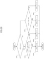
- FIG. 3 is a drawing illustrating symbols of various variables in an embodiment
- FIG. 4 is a flowchart illustrating a lane keeping control process and a lane departure warning control process
- FIG. 5 is a time chart indicating the influence of an outlier on an estimated value
- FIG. 6 is a flowchart illustrating a lane estimation process
- FIG. 7 is a graph indicating the value of an evaluation function in a case where weighting based on a reliability degree is not performed
- FIG. 8 is a graph indicating the value of an evaluation function in a case where weighting is performed based on a reliability degree
- FIG. 9 is a time chart illustrating state estimation performed with an extended Kalman filter
- FIG. 10 is a time chart illustrating state estimation performed according to moving horizon estimation
- FIG. 11 is a graph indicating the correlation between an error and a reliability base value Wtmp
- FIG. 12 is a graph indicating a method of correcting a reliability base value Wtmp
- FIG. 13 is a drawing indicating methods of correcting reliability degrees W of left and right lane marking positions dl and dr;
- FIG. 14 is a drawing illustrating a method of interpolating a reliability degree W
- FIG. 15 is a drawing illustrating a correlation between the recognizable range of an external recognition sensor and a leading vehicle
- FIG. 16 is a drawing indicating a method of correcting a reliability degree W of a yaw angle ⁇ ;
- FIG. 17 is a drawing indicating a method of correcting a reliability degree W of a curvature ⁇ s measured using an external recognition sensor
- FIG. 18 is a drawing indicating a method of correcting a reliability degree W of a curvature ⁇ m obtained from map information
- FIG. 19 is a flowchart illustrating a process of determining the accuracy of a curvature ⁇ s.
- FIG. 20 is a flowchart illustrating a process of determining the accuracy of a curvature ⁇ m.
- Embodiments of a vehicle control device, a vehicle control method, a vehicle motion control system, and a lane estimation device according to the present invention are described below with reference to the drawings.
- FIG. 1 is a system block diagram illustrating an embodiment of a vehicle motion control system 20 included in a vehicle (automobile) 10 .
- Vehicle motion control system 20 includes at least one of an automatic driving mode in which a steering control, in other words, a lane keeping control, is performed such that vehicle 10 travels along a driving lane without involving the operation of a steering wheel 11 by a driver and a driver assistance mode in which the driver is notified that vehicle 10 is about to depart from the driving lane.
- a steering control in other words, a lane keeping control
- the automatic driving mode may be configured such that a vehicle speed control is performed along with the steering control described above.
- Vehicle motion control system 20 includes a control unit 21 as an example of a vehicle control device.
- Control unit 21 is an electronic control device mainly comprised of a microcomputer 21 a that includes a processor, a memory, an I/O unit, and a bus connecting these components.
- Microcomputer 21 a functions as a controller that performs a vehicle control including the steering control by performing calculations based on input information and outputting control commands as the calculation results.
- An external recognition sensor 22 measures a scene in front of vehicle 10 (own vehicle), detects lane markings (e.g., white lines or yellow lines) drawn on the road to define the right and left of a lane in which vehicle 10 is traveling and an object existing in front of vehicle 10 , and measures relative distances from vehicle 10 to the lane markings and a relative distance from vehicle 10 to the object.
- lane markings e.g., white lines or yellow lines
- External recognition sensor 22 may be implemented by a sensor such as a stereo camera or a LiDAR (Light Detection and Ranging, Laser Imaging Detection and Ranging) sensor that can measure both the shape of an object in front of the vehicle and the distance from vehicle 10 to the object.
- a sensor such as a stereo camera or a LiDAR (Light Detection and Ranging, Laser Imaging Detection and Ranging) sensor that can measure both the shape of an object in front of the vehicle and the distance from vehicle 10 to the object.
- LiDAR Light Detection and Ranging, Laser Imaging Detection and Ranging
- external recognition sensor 22 may be implemented by combining multiple sensors such as a monocular camera, a millimeter-wave radar, and an ultrasonic sensor that can measure either the shape of an object in front of the vehicle or the distance to the object.
- sensors such as a monocular camera, a millimeter-wave radar, and an ultrasonic sensor that can measure either the shape of an object in front of the vehicle or the distance to the object.
- an external recognition processing device 23 calculates relative distances between vehicle 10 and the right and left lane markings, a yaw angle of vehicle 10 , and curvatures of the lane markings corresponding to the curvature of the lane (in other words, a travel route).
- external recognition processing device 23 recognizes a leading vehicle traveling in front of vehicle 10 based on the information on the object in front of vehicle 10 detected by external recognition sensor 22 , and calculates a relative distance between vehicle 10 and the leading vehicle.
- External recognition sensor 22 and external recognition processing device 23 described above constitute an external recognition unit that recognizes external information of vehicle 10 .
- the information on the relative distances between vehicle 10 and the right and left lane markings, the yaw angle, and the curvatures of the lane markings calculated by external recognition processing device 23 is information on lane markings.
- the information on lane markings obtained using external recognition sensor 22 is referred to as first information.
- a global positioning system (GPS) 24 measures positional relationships between vehicle 10 and multiple GPS satellites, and calculates a latitude and a longitude indicating a current location of vehicle 10 and a directional angle of vehicle 10 based on the measurement results.
- a navigation system 25 Based on information on the current location of vehicle 10 obtained from GPS 24 and map information, a navigation system 25 displays, on an accompanying liquid-crystal display, a map screen in which a marker indicating the current location of vehicle 10 is superimposed on a road map around vehicle 10 .
- navigation system 25 searches for the optimum guidance route from the current location to a destination specified by the driver, superimposes the guidance route on the map screen, and provides guidance such as a course change to the driver by, for example, displaying branch information on the map screen or providing spoken information (in other words, sound).
- Control unit 21 can obtain information on the shape of a road on which vehicle 10 is traveling by using navigation system 25 .
- Navigation system 25 corresponds to a road shape information acquisition unit that obtains information on a road shape.
- control unit 21 calculates information on the curvature of a lane based on the information on the road shape obtained from navigation system 25 .
- the information on the curvature of a lane based on the information on the road shape obtained by navigation system 25 is referred to as second information.
- a vehicle behavior detection device 26 includes multiple sensors that detect physical quantities related to the motion state of vehicle 10 .
- vehicle motion control system 20 includes a steering angle sensor 26 a for detecting the steering angle of steering wheel 11 , a turning angle sensor 26 b for detecting the turning angle of front wheels 10 FL and 10 FR that are turning wheels of vehicle 10 , a vehicle speed sensor 26 c for detecting a vehicle speed that is the traveling speed of vehicle 10 , a lateral G sensor 26 d for detecting the lateral acceleration of vehicle 10 , and a yaw rate sensor 26 e for detecting the yaw rate of vehicle 10 .
- a steering angle sensor 26 a for detecting the steering angle of steering wheel 11
- a turning angle sensor 26 b for detecting the turning angle of front wheels 10 FL and 10 FR that are turning wheels of vehicle 10
- vehicle speed sensor 26 c for detecting a vehicle speed that is the traveling speed of vehicle 10
- a lateral G sensor 26 d for detecting the lateral acceleration of vehicle 10
- a yaw rate sensor 26 e for detecting the yaw rate of vehicle 10 .
- vehicle behavior detection device 26 corresponds to a vehicle motion state detection unit that detects physical quantities related to the motion state of vehicle 10 .
- the vehicle speed, the lateral acceleration, and the yaw rate detected by vehicle behavior detection device 26 are information on the behavior of vehicle 10 .
- the information on the behavior of vehicle 10 is referred to as third information.
- control unit 21 estimates lane information that includes information on the curvatures of lane markings and information on the relative positions of vehicle 10 with respect to the lane markings.
- control unit 21 includes a function as a lane estimation device that estimates the lane information.
- control unit 21 calculates a target steering angle for causing vehicle 10 to travel along a driving lane based on estimated lane information, and sends a signal (in other words, a steering angle command) indicating the calculated target steering angle to a steering control device 27 .
- the function for controlling the steering angle based on the lane information corresponds to the lane keeping control.
- control unit 21 determines whether vehicle 10 is about to depart from the driving lane based on the estimated lane information; and when vehicle 10 is about to depart from the driving lane, control unit 21 performs a lane departure warning control to warn the driver of the lane departure.
- the driver can turn the automatic driving mode and the driver assistance mode on and off by, for example, operating switches.
- Vehicle motion control system 20 includes an alarm device 28 , a head-up display (HUD) device 29 , and a steering vibration device 30 .
- HUD head-up display
- Control unit 21 warns the driver of the lane departure by one or more of the following methods: generating a voice or an alarm sound using alarm device 28 , displaying a warning message on head-up display (HUD) device 29 , vibrating steering wheel 11 using steering vibration device 30 , and applying torque to steering wheel 11 in a direction to return to the lane.
- HUD head-up display
- Alarm device 28 provides various warnings by generating speech and alarm sounds.
- HUD device 29 displays images in the field of vision of the driver who is looking ahead. For example, HUD device 29 displays guidance provided by navigation system 25 and various warnings.
- Steering vibration device 30 provides various warnings by vibrating steering wheel 11 .
- a steering device 31 includes a steering actuator such as a motor that generates steering force. Steering device 31 assists the driver in operating steering wheel 11 by using the steering actuator, and also enables automatic steering of front wheels 10 FL and 10 FR with the steering actuator.
- a steering actuator such as a motor that generates steering force.
- Steering device 31 assists the driver in operating steering wheel 11 by using the steering actuator, and also enables automatic steering of front wheels 10 FL and 10 FR with the steering actuator.
- Steering control device 27 calculates steering torque for achieving a target steering angle instructed by control unit 21 , and causes the steering actuator of steering device 31 to generate the steering torque.
- control unit 21 can calculate the steering torque for achieving the target steering angle and output a steering torque command as a control command for steering.
- control unit 21 Next, a lane information estimation process performed by control unit 21 is described in detail.
- FIG. 2 is a block diagram illustrating a lane information estimation function of control unit 21 (microcomputer 21 a ).
- a first information acquisition unit 211 obtains first information, which is information regarding lane markings, by using external recognition processing device 23 .
- a second information acquisition unit 212 obtains second information, which is information regarding the curvature of a lane, by using navigation system 25 .
- a third information acquisition unit 213 obtains third information, which is information regarding the behavior of vehicle 10 , by using vehicle behavior detection device 26 .
- a reliability setting unit 214 sets reliability degrees used to weight the first information, the second information, and the third information based on information from external recognition processing device 23 , navigation system 25 , and vehicle behavior detection device 26 .
- a lane estimation unit 215 estimates lane information that includes information on the curvatures of lane markings and information on the relative positions of vehicle 10 with respect to the lane markings.
- a lane keeping control unit 216 calculates a target steering angle for causing vehicle 10 to travel along the driving lane based on the lane information estimated by lane estimation unit 215 . Then, lane keeping control unit 216 sends a signal indicating the calculated target steering angle to steering control device 27 .
- lane keeping control unit 216 outputs a steering control command to perform a lane keeping control for vehicle 10 .
- a lane departure warning unit 217 determines whether vehicle 10 is about to depart from the driving lane.
- lane departure warning unit 217 outputs an alarm generation command to, for example, alarm device 28 to notify the lane departure to the driver.
- FIG. 3 illustrates symbols of various variables used in the present embodiment.
- the distance between vehicle 10 and the left lane marking is represented by dl [m]
- the distance between vehicle 10 and the right lane marking is represented by dr [m]
- the yaw angle of vehicle 10 is represented by a [rad]
- the curvature of a lane (travel route) is represented by ⁇ [1/m]
- the road width (the distance between the right lane marking and the left lane marking) is represented by D [m]
- the vehicle speed is represented by V [m/s]
- the yaw rate is represented by ⁇ [rad/s]
- the lateral position indicating the amount of lateral shift of vehicle 10 from the center of the lane is represented by z [m].
- the distance dl is referred to as a left lane marking position dl
- the distance dr is referred to as a right lane marking position dr.
- the left lane marking position dl and the right lane marking position dr are information regarding the relative positions of vehicle 10 with respect to the lane markings.
- the curvature ⁇ of a travel route based on the lane markings recognized by external recognition sensor 22 is represented by Ks
- the curvature ⁇ of a travel route based on the shape of a road, which is obtained by navigation system 25 and on which vehicle 10 is traveling is represented by ⁇ m.
- FIG. 4 is a flowchart illustrating a lane keeping control process and a lane departure warning control process performed by control unit 21 .
- microcomputer 21 a of control unit 21 executes the routine illustrated by the flowchart of FIG. 4 at regular intervals of, for example, 50 ms by interrupt processing.
- control unit 21 obtains, as first information, lane marking information that includes the left lane marking position dl, the right lane marking position dr, the yaw angle ⁇ , and the curvature ⁇ s by using external recognition processing device 23 .
- control unit 21 calculates the curvature ⁇ m of a road at the current location of vehicle 10 based on information that is regarding the road shape at the current location of vehicle 10 and obtained from navigation system 25 , and also calculates a change amount C [1/m/m] of the curvature ⁇ m.
- the curvature ⁇ m and the change amount C are second information regarding the curvature of a lane.
- the change amount C is a change amount of the curvature ⁇ m per unit travel distance of vehicle 10 .
- the change amount C is a value that satisfies Formula 1.
- d/ds is a derivative value with respect to the travel distance s of vehicle 10 .
- control unit 21 can calculate the curvature ⁇ m as the reciprocal of the radius of a circle that passes through three nodes close to the current location of vehicle 10 .
- control unit 21 can calculate an approximate curve indicating the relationship of the curvature ⁇ m with the travel distance s by using the curvature ⁇ m calculated based on multiple nodes around the current location of vehicle 10 and the distances between the nodes, and calculate the slope of the approximate curve at the current location of vehicle 10 as the change amount C.
- control unit 21 can store the curvature ⁇ m calculated at each time point, and calculate the approximate curve with the travel distance s corrected using the amount of movement of vehicle 10 .
- control unit 21 can calculate the curvature ⁇ m using map information in which road shapes are represented with nodes and links.
- a map in which road shapes are represented with nodes and links is sufficient for navigation system 25 , and it is not necessary to use a so-called high-precision map including information such as lanes and road signs.
- control unit 21 can generate a local map (e.g., a road network map) of an area around vehicle 10 based on surrounding environments such as curbs measured using, for example, a LiDAR.
- a local map e.g., a road network map
- control unit 21 can calculate the curvature ⁇ m and the change amount C as the second information based on the generated map information.
- the road shape information acquisition unit is not limited to navigation system 25 , and control unit 21 can obtain road shapes using a sensor such as a LiDAR that is provided separately from external recognition sensor 22 .
- the road shape information obtained by control unit 21 from, for example, navigation system 25 is information regarding the shape of a road that includes the outside of lane markings and on which vehicle 10 can travel and is information regarding the shape of a road of which a boundary is defined by, for example, a guardrail or a curb outside of the lane markings.
- control unit 21 can use a curvature radius 1/ ⁇ instead of the curvature ⁇ as a quantity indicating the degree of curvature of a lane (road).
- control unit 21 of the present embodiment uses the curvature ⁇ .
- control unit 21 obtains information on the vehicle speed V and the yaw rate ⁇ of vehicle 10 from vehicle behavior detection device 26 as the third information regarding the behavior of vehicle 10 .
- control unit 21 sets a reliability degree W (in other words, a weight) for the information obtained at each of step S 501 (first information acquisition unit 211 ), step S 502 (second information acquisition unit 212 ), and step S 503 (third information acquisition unit 213 ).
- a reliability degree W in other words, a weight
- the reliability degree W is an index value of the accuracy of information. A process of calculating the reliability degree W by control unit 21 is described later in detail.
- Control unit 21 then proceeds to step S 505 (lane estimation unit 215 ) and estimates lane information including the lateral position z, the yaw angle ⁇ , the road width D, and the curvature ⁇ .
- control unit 21 weights the first information obtained at step S 501 (first information acquisition unit 211 ), the second information obtained at step S 502 (second information acquisition unit 212 ), and the third information obtained at step S 503 (third information acquisition unit 213 ) based on the reliability degrees W set at step S 504 (reliability setting unit 214 ), and performs state estimation calculations to calculate estimated values of the lateral position z, the yaw angle ⁇ , the road width D, and the curvature ⁇ as the lane information.
- control unit 21 estimates lane information based on the second information obtained from navigation system 25 and the third information regarding the behavior of vehicle 10 in addition to the first information obtained from external recognition sensor 22 . This makes it possible to improve the performance of recognizing lane markings and improve the performance of the lane keeping control.
- control unit 21 can estimate a lane in which vehicle 10 needs to travel and continue the lane keeping control. This in turn makes it possible to increase areas in which the lane keeping control can be performed.
- control unit 21 performs weighting based on reliability degrees W of information items used in the estimation of lane information. This makes it possible to reduce the influence of information with a large error on the estimation result, and makes it possible to incorporate accurate information in the estimation of lane information and thereby improve the accuracy of lane information.
- control unit 21 proceeds to step S 506 to determine whether the lane keeping control is in the ON state, in other words, whether the driver of vehicle 10 has selected the automatic driving mode so that the lane keeping control is performed.
- control unit 21 When the lane keeping control is in the ON state, i.e., the automatic driving mode is selected, control unit 21 proceeds to step S 507 ; and when the lane keeping control is in the OFF state, control unit 21 proceeds to step S 509 .
- control unit 21 calculates a target steering amount (in other words, a steering control command) necessary for vehicle 10 to travel along the driving lane based on the lane information obtained at step S 505 (lane estimation unit 215 ).
- control unit 21 proceeds to step S 508 to output a control command indicating the target steering amount (in other words, a target steering angle) obtained at step S 507 to steering control device 27 , and then ends the control cycle.
- Steering control device 27 controls the steering actuator of steering device 31 to achieve the target steering amount instructed by control unit 21 .
- control unit 21 determines whether the lane departure warning control is in the ON state, in other words, whether the driver of vehicle 10 has selected the driver assistance mode so that the lane departure warning control is performed.
- control unit 21 proceeds to step S 510 .
- control unit 21 ends the control cycle.
- control unit 21 determines whether vehicle 10 is about to depart from the driving lane based on the lane information obtained at step S 505 (lane estimation unit 215 ).
- control unit 21 proceeds to step S 511 and outputs an activation command to alarm device 28 .
- control unit 21 warns the driver of vehicle 10 that vehicle 10 is about to depart from the driving lane by activating, for example, alarm device 28 , HUD device 29 , and/or steering vibration device 30 and then ends the control cycle.
- control unit 21 does not have to warn the driver and therefore ends the control cycle without activating alarm device 28 .
- the system may be configured such that both of the lane keeping control and the lane departure warning control are performed concurrently. For example, even while the lane keeping control is being performed, the lane departure warning may be activated when vehicle 10 is about to depart from the driving lane.
- lane estimation unit 215 in other words, the process at step S 505 of FIG. 4 , is described in detail.
- lane estimation unit 215 estimates a state x [k] (state estimated values) including the lateral position z, the yaw angle ⁇ , the road width D, and the curvature ⁇ by using an output y [k] (observed values) including the left lane marking position dl, the right lane marking position dr, the yaw angle ⁇ , the curvature Ks, and the curvature ⁇ m and an input u [k] (control input values) including the vehicle speed V, the yaw rate ⁇ , and the curvature change amount C.
- x, u, and y indicate a state vector (state estimated values), an input vector (control input values), and an output vector (observed values), and T is a symbol representing a transpose matrix.
- state equations indicating the dynamics of the system can be expressed by Formulas 5 and 6
- observation equations expressing the output vector using the state vector can be expressed by Formulas 7 and 8.
- ⁇ t represents the time between samplings (in other words, a sampling period)
- v and w represent the system noise of a mean zero and covariance matrix Q and the observed noise of a mean zero and covariance matrix R, respectively.
- an evaluation function J represented by Formula 9 is set as an indicator of the accuracy of state estimation.
- T indicates a current sampling
- H indicates an evaluation period length, in other words, the number of samplings to be included in the evaluation function J
- S Q , S R , and S P represent weighting matrices.
- (x with a hat “ ⁇ circumflex over ( ) ⁇ ”) indicates an estimated value (estimated state) of the state x
- x ⁇ circumflex over ( ) ⁇ with the superscript of “-” indicates an estimated value in the previous sampling.
- MHE moving horizon estimation
- the first term on the right-hand side of Formula 9 is a term to make the change amount of the state estimated value between samplings match the equation of state represented by Formula 6, and minimizing this term makes it possible to perform state estimation that conforms to the system dynamics.
- the second term on the right side of Formula 9 is a term to make the relationship between a state estimated value and an observed value in each sampling match the observation equation of Formula 8, and minimizing this term makes it possible to perform state estimation corresponding to the observed value.
- the third term on the right-hand side of Formula 9 is a term for evaluating the amount of change from the state estimated value obtained in the previous sampling, and minimizing this term makes it possible to incorporate information earlier than the evaluation period length into the estimation.
- the degrees of influence of the terms on the right-hand side of Formula 9 on the state estimation are determined by the weighting matrices S Q , S R and S P .
- the inverse matrices of covariance matrices of system noise and observed noise are used as the weighting matrices S Q and S R
- the inverse matrix of an error covariance matrix of an estimated state obtained when an extended Kalman filter is applied to the system represented by Formulas 5 through 8 is used as the weighting matrix S P .
- an observed value hereafter referred to as an outlier
- the outlier may affect the estimated value and cause the estimated value to deviate significantly from the true value.
- control unit 21 (lane estimation unit 215 ) performs state estimation such that the influence of the outliers is reduced by decreasing the weights of the observed values.
- FIG. 5 illustrates the correlation among an observed value, an estimated value, and the weight of the observed value.
- a dashed-dotted line indicates an estimated value obtained when state estimation is performed without considering any outlier
- a solid line indicates an estimated value obtained when state estimation is performed by decreasing the weight of the outlier.
- a dotted line indicates the true value
- circles indicate measured values.
- Lane estimation unit 215 calculates the weighting matrix S R for the second term on the right side of Formula 9 based on Formula 10 using a reliability degree W calculated by reliability setting unit 214 .
- S R R ⁇ 1 W [Formula 10]
- control unit 21 can also change the weighting matrix S Q for the first term on the right-hand side of Formula 9 according to the reliability degree W.
- control unit 21 changes only the weighting matrix S R for the second term on the right side of Formula 9 according to the reliability degree W.
- control unit 21 reliability setting unit 214
- FIG. 6 is a flowchart illustrating the process at step S 505 (lane estimation unit 215 ) of the flowchart of FIG. 4 .
- control unit 21 calculates the weighting matrices S Q , S R , and S P for the terms on the right side of Formula 9.
- control unit 21 calculates the weighting matrix S R for the second term on the right side of Formula 9 based on Formula 10 using the reliability degree W.
- Control unit 21 can use a known solution method such as sequential quadratic programming or an interior point method to solve the nonlinear programming problem described above. Using the sequential quadratic programming makes it possible to obtain the solution at a relatively high speed.
- control unit 21 can impose a predetermined constraint as described later on the calculation (lane information estimation) of the estimated value x ⁇ circumflex over ( ) ⁇ [k].
- minimizing the value of the evaluation function J represented by Formula 11 is equivalent to estimating the variable y after performing weighting with a coefficient w to indicate which one of the two observed values is to be trusted.
- the evaluation function J of Formula 9 includes more terms to be added compared with the evaluation function J of Formula 11 and includes terms that are not in quadratic form, the evaluation function J of Formula 9 is more complicated than the evaluation function J of Formula 11. However, similarly to the evaluation function J of Formula 11, the influence of an outlier on the estimation result can be reduced by decreasing the weight of the outlier.
- control unit 21 performs moving horizon estimation in which a state estimated value is obtained by performing an optimization calculation for minimizing the value of the evaluation function J of Formula 9.
- control unit 21 may be configured to design a known extended Kalman filter for the system represented by Formulas 5 through 8 and to change the covariance matrix R used in the extended Kalman filter according to the reliability degree W.
- FIG. 9 illustrates sequential computation in the extended Kalman filter in which the estimation result in the previous sampling is corrected using the output and input of the current sampling.
- FIG. 10 illustrates moving horizon estimation in which an estimated value is calculated using all inputs (control input values) and outputs (observed values) within a given evaluation period (in other words, within an estimation horizon).
- control unit 21 employs the moving horizon estimation instead of the extended Kalman filter.
- control unit 21 can impose a constraint on the estimated value.
- the constraint on the estimated value is a condition that is expressed by an equation or an inequality and that needs to be satisfied by the estimated value calculated to minimize the evaluation function J.
- variable y when a constraint “variable y ⁇ 4” is imposed, the variable y needs to be less than or equal to 4. Accordingly, the variable y that minimizes the evaluation function J under the constraint “variable y ⁇ 4” becomes 4.
- Control unit 21 imposes constraints as described below on estimated values.
- control unit 21 imposes a constraint represented by Formula 12 on an estimated value ⁇ circumflex over ( ) ⁇ of the curvature ⁇ such that the change amount of the estimated value ⁇ circumflex over ( ) ⁇ of the curvature ⁇ becomes less than or equal to a constant value ( ⁇ max ).
- ⁇ circumflex over ( ) ⁇ ⁇ is an estimated value of the curvature ⁇ in the previous sampling.
- ⁇ max in Formula 12 is the upper limit of the change amount of the curvature ⁇ per unit travel distance of vehicle 10 .
- ⁇ max is set based on the maximum value of the curvature change rate of a general road.
- control unit 21 can calculate the value of ⁇ max based on the change amount of the curvature of a road obtained from map information, and can change the value of ⁇ max for each sampling.
- control unit 21 can prevent the estimated value ⁇ circumflex over ( ) ⁇ of the curvature ⁇ from deviating significantly from the actual value even if, for example, an observed value of the curvature ⁇ deviating significantly from the actual value is used for state estimation.
- vehicle 10 when vehicle 10 is traveling along a driving lane, the lateral position z of vehicle 10 does not change rapidly.
- control unit 21 imposes a constraint represented by Formula 13 on an estimated value z ⁇ circumflex over ( ) ⁇ of the lateral position z such that the change amount of the estimated value z ⁇ circumflex over ( ) ⁇ of the lateral position z becomes less than or equal to a constant value ( ⁇ z max ).
- ⁇ z max in Formula 13 is the upper limit of the change amount of the lateral position z per unit time.
- ⁇ z max is based on the maximum value of the change amount of the lateral position z that can generally occur when vehicle 10 travels along a driving lane.
- control unit 21 can change the upper limit ⁇ z max according to the vehicle speed V of vehicle 10 .
- control unit 21 can prevent the estimated value z ⁇ circumflex over ( ) ⁇ of the lateral position z from deviating significantly from the actual value even if, for example, the observed values of the left lane marking position dl and/or the right lane marking position dr that deviating significantly from the actual values is used for state estimation.
- the road width of a major road such as an arterial road or an expressway is determined by a standard.
- control unit 21 imposes a constraint represented by Formula 14 on an estimated value D ⁇ circumflex over ( ) ⁇ of the road width D so that the estimated value D ⁇ circumflex over ( ) ⁇ of the road width D falls within a predetermined range.
- D min indicates the minimum value (lower limit) of the road width D
- D max indicates the maximum value (upper limit) of the road width D.
- the minimum value D min is set at 2.5 m and the maximum value D max is set at 4 m.
- control unit 21 can prevent the estimated value of the road width D from deviating significantly from the actual value when, for example, the position of a road marking other than a lane marking is measured.
- control unit 21 For each of the observed values (the left and right lane marking positions dl and dr, the yaw angle ⁇ , the curvature ⁇ s, and the curvature ⁇ m), control unit 21 sets a reliability degree W that is an index value indicating the accuracy (preciseness or correctness) of a measurement result.
- the reliability degree W takes a value between 0 and 1 (0 ⁇ W ⁇ 1). As the value of the reliability degree W becomes closer to 1, the accuracy becomes higher; and as the value of the reliability degree W becomes closer to 0, the accuracy becomes lower.
- control unit 21 can correctly estimate a state by using an observed value whose reliability degree W is close to 1 for state estimation.
- an observed value of which reliability degree W is close to 0 in other words, an outlier
- Control unit 21 calculates the reliability base value Wtmp according to Formula 15.
- ⁇ is the standard deviation of the error between the observed value y and the estimated value y ⁇ circumflex over ( ) ⁇
- G 2 is the variance of the error between the observed value y and the estimated value y ⁇ circumflex over ( ) ⁇ .
- FIG. 11 indicates the correlation between the error between the observed value y and the estimated value y ⁇ circumflex over ( ) ⁇ and the reliability base value Wtmp.
- control unit 21 sets the reliability base value Wtmp to 1, which is the maximum value.
- control unit 21 gradually decreases the reliability base value Wtmp as the error increases to reduce the influence of the less-reliable observed value y on the state estimation.
- the error criterion is not limited to 3 ⁇ .
- Control unit 21 can use, for example, ⁇ instead of 3 ⁇ for the calculation of the reliability base value Wtmp when it is desired to perform state estimation using only information with a small error.
- control unit 21 can use, for example, 5 ⁇ instead of 3 ⁇ for the calculation of the reliability base value Wtmp when it is desired to perform state estimation also using information with a relatively large error.
- control unit 21 sets the reliability base value Wtmp according to an error between the observed value y and the estimated value y ⁇ circumflex over ( ) ⁇ to set a weight corresponding to the error.
- the weight is set according to an error, once the estimation fails and the estimated value y ⁇ circumflex over ( ) ⁇ deviates significantly from the true value, the weight becomes small even if a true value is measured, and it may become impossible to correct the estimated value y ⁇ circumflex over ( ) ⁇ .
- control unit 21 sets the final reliability degree W by correcting the reliability base value Wtmp according to, for example, the degree of variation of the observed value, the traveling state of vehicle 10 , and the surrounding environment of vehicle 10 .
- FIG. 12 indicates correction patterns for correcting the reliability base value Wtmp.
- control unit 21 fixes the reliability degree W at 1 as indicated by a dashed-dotted line in FIG. 12 .
- lane estimation is performed based on the observed value regardless of the error between the observed value y and the estimated value y ⁇ circumflex over ( ) ⁇ .
- control unit 21 corrects the reliability degree W such that the reliability degree W becomes smaller than the reliability base value Wtmp as indicated by a dotted line in FIG. 12 .
- Methods of setting the reliability degree W smaller than the reliability base value Wtmp include, for example, a method in which the square value of the reliability base value Wtmp is set as the reliability degree W and a method in which a value obtained by multiplying the reliability base value Wtmp by a constant between 0 and 1 is set as the reliability degree W.
- control unit 21 sets the square value of the reliability base value Wtmp as the reliability degree W, the influence of an error on the reliability degree W can be increased.
- control unit 21 sets a value obtained by multiplying the reliability base value Wtmp by a constant as the reliability degree W, the influence of an error on state estimation can be reduced at a constant percentage regardless of the size of the error.
- control unit 21 can change the methods of setting the reliability degree W smaller than the reliability base value Wtmp according to, for example, the observed value being processed or a condition based on which the observed value is determined to be unreliable.
- control unit 21 sets the reliability degree W to match the reliability base value Wtmp as indicated by a solid line in FIG. 12 .
- FIG. 13 indicates conditions for correcting reliability degrees W of the left and right lane marking positions dl and dr measured using external recognition sensor 22 and the corrected reliability degrees W.
- the method in which the square value of the reliability base value Wtmp is set as the reliability degree W is used as the method for making the reliability degrees W of the left and right lane marking positions dl and dr smaller than the reliability base value Wtmp.
- control unit 21 sets the reliability degrees W of the left and right lane marking positions dl and dr to values that are less than the reliability base value Wtmp as indicated by the dotted line in FIG. 12 .
- control unit 21 changes the reliability degree W abruptly from the reliability base value Wtmp to the square value of the reliability base value Wtmp, the estimated value also changes abruptly, and the stability of steering control may be impaired.
- control unit 21 can gradually change the reliability degree W between the reliability base value Wtmp and the square value of the reliability base value Wtmp.
- FIG. 14 is a drawing used to describe a method of gradually changing the reliability degree W.
- Control unit 21 sets two thresholds representing a condition for correcting the reliability degree W and gradually changes the reliability degree W from the reliability base value Wtmp to the square value of the reliability base value Wtmp while the correction condition changes from a first threshold to a second threshold.
- control unit 21 starts to decrease the reliability degree W when the distance between vehicle 10 and the intersection decreases to the first threshold.
- control unit 21 continuously changes the reliability degree W from the reliability base value Wtmp to the square value of the reliability base value Wtmp such that the reliability degree W reaches the square value of the reliability base value Wtmp when the distance between vehicle 10 and the intersection reaches the second threshold that is shorter than the first threshold.
- control unit 21 can continuously change the reliability degree W from the reliability base value Wtmp to the square value of the reliability base value Wtmp by an interpolation calculation using, for example, a cubic function.
- Examples of situations in which vehicle 10 is stopped in a driving lane may include a case in which vehicle 10 is stopped at, or immediately before, a stop line of an intersection while waiting for a traffic light, and a case in which vehicle 10 is stopped behind a stopped leading vehicle.
- external recognition sensor 22 cannot measure the left and right lane marking positions dl and dr because no lane marking exists in an intersection.
- external recognition sensor 22 may not be able to correctly measure the left and right lane marking positions dl and dr because the leading vehicle blocks a part of a recognizable area of external recognition sensor 22 .
- FIG. 15 is a drawing illustrating a state in which the leading vehicle narrows the recognizable area of external recognition sensor 22 .
- a part behind the leading vehicle from the viewpoint of external recognition sensor 22 is an area that cannot be measured by external recognition sensor 22 .
- control unit 21 sets the reliability degrees W of the left and right lane marking positions dl and dr to the square value of the reliability base value Wtmp.
- control unit 21 can proceed with the correction of the estimated values by setting the reliability degrees W to 1 and thereby incorporating the observed values of the left and right lane marking positions dl and dr into state estimation.
- control unit 21 presumes that the left and right lane marking positions dl and dr are correctly measured and sets the reliability degrees W of the left and right lane marking positions dl and dr to 1.
- control unit 21 can, for example, store observed values obtained within a predetermined period of time in the past in a memory, calculate a variance using the stored observed values, and determine the degree of measurement variation of the observed values based on the variance.
- control unit 21 can obtain, by sequential computation, a variance such that the influence of an observed value gradually decreases as the observed value becomes older on a time-series basis and use the variance to determine the measurement variation of observed values.
- control unit 21 determines the degree of variation of the yaw angle ⁇ and the degree of variation of the curvature ⁇ s for the condition [T-1-3] in FIG. 13 .
- control unit 21 determines that the left and right lane marking positions dl and dr are correctly measured only when the road width D measured based on information on the left and right lane marking positions dl and dr is within a predetermined range so that a result of erroneously measuring a lane marking of a lane different from the driving lane is not used for state estimation.
- the predetermined range of the road width D is based on the road widths of general roads and is, for example, greater than or equal to 2.5 m and less than or equal to 4 m.
- control unit 21 sets the reliability degree W of one of the right and left lane marking positions with a smaller measurement variation, i.e., one of the right and left lane marking positions that is supposed to be measured correctly, to 1, and sets the reliability degree W of the other one of the right and left lane marking positions to the reliability base value Wtmp.
- control unit 21 sets the reliability degrees W of the left and right lane marking positions dl and dr to the square value of the reliability base value Wtmp.
- control unit 21 sets the reliability degrees W of the left lane marking position dl and the right lane marking position dr to the square value of the reliability base value Wtmp.
- the process of correcting the reliability degrees W in each of the conditions [T-1-3]-[T-1-5] and [T-1-7] described above is a process of correcting the reliability degrees W of the left lane marking position dl and the right lane marking position dr according to the variations of observed values.
- control unit 21 determines that a condition [T-1-8] of FIG. 13 is satisfied and sets the reliability degrees W of the left lane marking position dl and the right lane marking position dr to the reliability base value Wtmp.
- control unit 21 can incorporate the measurement results of the left and right lane marking positions dl and dr into state estimation (lane estimation) when the left and right lane marking positions dl and dr are measured correctly, and can perform state estimation (lane estimation) while reducing the influence of the measurement results of the left and right lane marking positions dl and dr when the left and right lane marking positions dl and dr are not measured correctly.
- FIG. 16 indicates conditions for correcting the reliability degree W of the yaw angle ⁇ measured using external recognition sensor 22 and the corrected reliability degree W.
- control unit 21 generally uses information on the left and right lane marking positions dl and dr to calculate the yaw angle ⁇ with external recognition sensor 22 .
- Examples of situations in which vehicle 10 is stopped in a driving lane may include a case in which vehicle 10 is stopped at, or immediately before, a stop line of an intersection while waiting for a traffic light, and a case in which vehicle 10 is stopped behind a stopped leading vehicle.
- external recognition sensor 22 cannot measure the left and right lane marking positions dl and dr because no lane marking exists in an intersection.
- external recognition sensor 22 may not be able to correctly measure the left and right lane marking positions dl and dr because the leading vehicle blocks a part of a recognizable area of external recognition sensor 22 , as illustrated in FIG. 15 .
- reliability setting unit 214 of control unit 21 sets the reliability degree W of the yaw angle ⁇ to a value obtained by multiplying the reliability base value Wtmp by 10 ⁇ 3 .
- control unit 21 can proceed with the correction of the estimated value by setting the reliability degree to 1 and thereby incorporating the observed value of the yaw angle ⁇ into state estimation.
- control unit 21 sets the reliability degree W of the yaw angle ⁇ to 1 when the measurement variations of all of the left and right lane marking positions dl and dr, the yaw angle ⁇ , and the curvature ⁇ s are small.
- control unit 21 when calculating the yaw angle ⁇ using external recognition sensor 22 , control unit 21 generally uses information on the left and right lane marking positions dl and dr. Therefore, unless both of the left and right lane marking positions dl and dr are measured correctly, the yaw angle ⁇ cannot be calculated correctly.
- condition [T-2-3] of FIG. 16 includes the degrees of variation of the left and right lane marking positions dl and dr as decision conditions.
- control unit 21 calculates the curvature ⁇ s based on information on the left and right lane marking positions dl and dr, it is possible that the yaw angle ⁇ has not been calculated correctly when there is variation in the measurement result of the curvature ⁇ s. Therefore, the condition [T-2-3] of FIG. 16 also includes the degree of variation of the curvature ⁇ s as a decision condition.
- the leading vehicle blocks an area that is recognizable by external recognition sensor 22 , and external recognition sensor 22 may not be able to correctly measure the left and right lane marking positions dl and dr.
- the measurement accuracy of the yaw angle ⁇ also decreases.
- control unit 21 sets the reliability degrees W of the yaw angle ⁇ to a value obtained by multiplying the reliability base value Wtmp by 10 ⁇ 3 .
- control unit 21 when calculating the yaw angle ⁇ using external recognition sensor 22 , control unit 21 generally uses information on the left and right lane marking positions dl and dr. Accordingly, when the variation of at least one of the left and right lane marking positions dl and dr is large, control unit 21 cannot calculate the yaw angle ⁇ correctly.
- control unit 21 sets the reliability degree W of the yaw angle ⁇ to a value obtained by multiplying the reliability base value Wtmp by 10 ⁇ 3 .
- control unit 21 determines that a condition [T-2-6] of FIG. 16 is satisfied and sets the reliability degree W of the yaw angle ⁇ to the reliability base value Wtmp.
- control unit 21 can incorporate the measurement result of the yaw angle ⁇ into state estimation (lane estimation) when the yaw angle ⁇ is measured correctly, and can perform state estimation (lane estimation) while reducing the influence of the measurement result of the yaw angle ⁇ when the yaw angle ⁇ is not measured correctly.
- FIG. 17 indicates conditions for correcting the reliability degree W of the curvature ⁇ s measured using external recognition sensor 22 and the corrected reliability degree W.
- control unit 21 generally uses information on the left and right lane marking positions dl and dr when calculating the curvature ⁇ s using external recognition sensor 22 .
- Control unit 21 calculates the curvature ⁇ s based on information on the left and right lane marking positions dl and dr measured using external recognition sensor 22 .
- control unit 21 sets the reliability degree W of the curvature ⁇ s to a value obtained by multiplying the reliability base value Wtmp by 10 ⁇ 3 .
- control unit 21 sets the reliability degree W of the curvature ⁇ s measured using external recognition sensor 22 to a value obtained by multiplying the reliability base value Wtmp by 10 ⁇ 3 .
- Examples of situations in which vehicle 10 is stopped in a driving lane may include a case in which vehicle 10 is stopped at, or immediately before, a stop line of an intersection while waiting for a traffic light, and a case in which vehicle 10 is stopped behind a stopped leading vehicle.
- external recognition sensor 22 cannot measure the left and right lane marking positions dl and dr because no lane marking exists in an intersection.
- external recognition sensor 22 may not be able to correctly measure the left and right lane marking positions dl and dr because the leading vehicle blocks a part of the recognizable area of external recognition sensor 22 as illustrated in FIG. 15 .
- control unit 21 sets the reliability degrees W of the curvature ⁇ s measured using external recognition sensor 22 to a value obtained by multiplying the reliability base value Wtmp by 10 ⁇ 3 .
- control unit 21 sets the reliability degree W of the curvature ⁇ s to a value obtained by multiplying the reliability base value Wtmp by 10 ⁇ 3 .
- control unit 21 when calculating the curvature ⁇ s using external recognition sensor 22 , control unit 21 generally uses one or both of the left and right lane marking positions dl and dr measured using external recognition sensor 22 . Therefore, when the measurement variations of both of the left and right lane marking positions dl and dr are large, control unit 21 cannot measure the curvature ⁇ s correctly.
- control unit 21 sets the reliability degree W of the curvature ⁇ s to a value obtained by multiplying the reliability base value Wtmp by 10 ⁇ 3 .
- Control unit 21 measures the curvature ⁇ s using external recognition sensor 22 and also measures the curvature ⁇ m based on the shape of a road (map information) on which vehicle 10 is travelling and that is obtained by navigation system 25 .
- control unit 21 can calculate a curvature Kd of a travelled path of vehicle 10 based on the vehicle behavior.
- the difference between the curvature ⁇ s/ ⁇ m of a travel route measured using external recognition sensor 22 or navigation system 25 and the curvature Kd of a travelled path based on the vehicle behavior becomes sufficiently small.
- control unit 21 compares the curvature ⁇ s calculated using external recognition sensor 22 , the curvature ⁇ m obtained from map information, and the curvature ⁇ d calculated based on the behavior of vehicle 10 with each other; and when determining that the accuracy of the curvature ⁇ s calculated using external recognition sensor 22 is low, control unit 21 sets the reliability degree W of the curvature ⁇ s calculated using external recognition sensor 22 to a value obtained by multiplying the reliability base value Wtmp by 10 ⁇ 3 .
- control unit 21 determines that a condition [T-3-7] of FIG. 17 is satisfied, and sets the reliability degree W of the curvature ⁇ s calculated using external recognition sensor 22 to the reliability base value Wtmp.
- control unit 21 can incorporate the measurement result of the curvature ⁇ s into state estimation (lane estimation) when the curvature ⁇ s is correctly measured and can perform state estimation (lane estimation) while reducing the influence of the measurement result of the curvature ⁇ s when the curvature ⁇ s is not correctly measured.
- FIG. 18 indicates conditions for correcting the reliability degree W of the curvature ⁇ m obtained from map information and the corrected reliability degree W.
- Examples of errors in the curvature ⁇ m obtained from map information include an error caused by a GPS positioning error, an error caused when calculating the curvature ⁇ m based on multiple node points, and an error inherent in the map information.
- control unit 21 cannot determine whether such an error exists based on the comparison between the curvature ⁇ m obtained from map information and the estimated value, and the adverse effect of the observed value on the estimated value cannot be fully eliminated by just increasing the influence of the error on the reliability degree W.
- control unit 21 To correctly perform lane estimation, control unit 21 needs information on the curvature ⁇ of a travel route. If the curvature ⁇ s calculated using external recognition sensor 22 is apparently incorrect, control unit 21 needs to use the curvature ⁇ m obtained from map information to perform lane estimation.
- control unit 21 determines that the curvature ⁇ s is likely to be incorrect and sets the reliability degree W of the curvature ⁇ m obtained from map information to the reliability base value Wtmp so that lane estimation is performed based on the curvature ⁇ m obtained from map information as long as it does not have an error.
- control unit 21 obtains the curvature ⁇ s using external recognition sensor 22 in addition to the curvature ⁇ m based on map information. Also, control unit 21 can calculate the curvature Kd of a travelled path of vehicle 10 based on the vehicle behavior.
- control unit 21 compares the curvature ⁇ s calculated using external recognition sensor 22 , the curvature ⁇ m obtained from map information, and the curvature Kd calculated based on the behavior of vehicle 10 with each other; and when determining that the accuracy of the curvature ⁇ m obtained from map information is low, control unit 21 sets the reliability degree W of the curvature ⁇ m obtained from map information to a value obtained by multiplying the reliability base value Wtmp by 10 ⁇ 3 .
- control unit 21 determines that a condition [T-4-3] of FIG. 18 is satisfied, and sets the reliability degree W of the curvature ⁇ m obtained from map information to the reliability base value Wtmp.
- control unit 21 can incorporate the measurement result of the curvature ⁇ m into state estimation (lane estimation) when the curvature ⁇ m is correctly measured, and can perform state estimation (lane estimation) while reducing the influence of the measurement result of the curvature ⁇ m when the curvature ⁇ m is not correctly measured.
- Control unit 21 determines the accuracy of the curvatures ⁇ s and ⁇ m by comparing the curvature ⁇ s calculated using external recognition sensor 22 , the curvature ⁇ m obtained from map information, and the curvature ⁇ d of a travelled path calculated based on the behavior of vehicle 10 .
- control unit 21 calculates the curvature ⁇ d of a travelled path according to Formula 16.
- 6 indicates a steering angle
- A indicates a stability factor
- W b indicates a wheelbase
- V indicates a vehicle speed.
- FIG. 19 is a flowchart illustrating a process of calculating an accuracy JDG ⁇ s of the curvature ⁇ s measured using external recognition sensor 22 .
- the accuracy JDG ⁇ s is used to correct the reliability degree W of the curvature ⁇ s (i.e., the condition [T-3-6] of FIG. 17 ).
- control unit 21 sets JDG ⁇ s to 1 when determining that the accuracy of the curvature ⁇ s is high, and sets JDG ⁇ s to 0 when determining that the accuracy of the curvature ⁇ s is low.
- control unit 21 determines whether the previous value of the accuracy JDG ⁇ s of the curvature ⁇ s is 1.
- control unit 21 proceeds to step S 602 when the previous value of the accuracy JDG ⁇ s of the curvature ⁇ s is 1, or proceeds to step S 605 when the previous value of the accuracy JDG ⁇ s of the curvature ⁇ s is not 1 (in other words, when the previous value of the accuracy JDG ⁇ s of the curvature ⁇ s is 0).
- control unit 21 determines whether a first decision condition is satisfied.
- the first decision condition is satisfied when the absolute value of the difference between the curvature ⁇ s and the curvature ⁇ d is greater than a threshold Th1, and the absolute value of the difference between the curvature ⁇ s and the curvature ⁇ d is greater than the absolute value of the difference between the curvature ⁇ m and the curvature ⁇ d.
- the first decision condition that is, when the curvature ⁇ s calculated using external recognition sensor 22 deviates significantly from the curvature ⁇ d of the travelled path and the deviation is greater than the difference between the curvature ⁇ m obtained from map information and the curvature ⁇ d of the travelled path, the accuracy of the curvature ⁇ s is low (in other words, it is presumable that the curvature ⁇ s is incorrectly measured).
- control unit 21 proceeds to step S 603 and sets the accuracy JDG ⁇ s of the curvature ⁇ s to 0.
- control unit 21 proceeds to step S 604 and keeps the accuracy JDG ⁇ s of the curvature ⁇ s at 1.
- control unit 21 determines whether a second decision condition is satisfied.
- the second decision condition is satisfied when the absolute value of the difference between the curvature ⁇ s and the curvature ⁇ d is less than the threshold Th1.
- the accuracy of the curvature ⁇ s calculated using external recognition sensor 22 is high.
- control unit 21 proceeds to step S 606 and sets the accuracy JDG ⁇ s of the curvature ⁇ s to 1.
- control unit 21 proceeds to step S 607 and keeps the accuracy JDG ⁇ s of the curvature ⁇ s at 0 .
- Control unit 21 sets the accuracy JDG ⁇ s of the curvature ⁇ s as described above, and determines whether the condition [T-3-6] of FIG. 17 is satisfied based on the accuracy JDG ⁇ s.
- control unit 21 determines that the accuracy of the curvature ⁇ s is low and sets the reliability degree W of the curvature ⁇ s calculated using external recognition sensor 22 to a value obtained by multiplying the reliability base value Wtmp by 10 ⁇ 3 .
- FIG. 20 is a flowchart illustrating a process of calculating an accuracy JDG ⁇ m of the curvature ⁇ m obtained from map information.
- the accuracy JDG ⁇ m is used to correct the reliability degree W of the curvature ⁇ m (the condition [T-4-2] of FIG. 18 ).
- control unit 21 sets JDG ⁇ m to 1 when determining that the accuracy of the curvature ⁇ m is high, and sets JDG ⁇ m to 0 when determining that the accuracy of the curvature ⁇ m is low.
- control unit 21 determines whether the previous value of the accuracy JDG ⁇ m of the curvature ⁇ m is 1.
- control unit 21 proceeds to step S 702 when the previous value of the accuracy JDG ⁇ m of the curvature ⁇ m is 1, or proceeds to step S 705 when the previous value of the accuracy JDG ⁇ m of the curvature ⁇ m is not 1 (in other words, when the previous value of the accuracy JDG ⁇ m of the curvature ⁇ m is 0).
- control unit 21 determines whether a first decision condition is satisfied.
- the first decision condition is satisfied when the absolute value of the difference between the curvature ⁇ m and the curvature ⁇ d is greater than a threshold Th2 and the absolute value of the difference between the curvature ⁇ m and the curvature ⁇ d is greater than the absolute value of the difference between the curvature ⁇ s and the curvature ⁇ d.
- the first decision condition that is, when the curvature ⁇ m obtained from map information deviates significantly from the curvature ⁇ d of the travelled path and the deviation is greater than the difference between the curvature ⁇ s calculated using external recognition sensor 22 and the curvature ⁇ d of the travelled path, the accuracy of the curvature ⁇ m is low, in other words, it is presumable that the curvature ⁇ m is incorrectly measured.
- control unit 21 proceeds to step S 703 and sets the accuracy JDG ⁇ m of the curvature ⁇ m to 0.
- control unit 21 proceeds to step S 704 and keeps the accuracy JDG ⁇ m of the curvature ⁇ m at 1.
- control unit 21 proceeds to step S 705 and determines whether a second decision condition is satisfied.
- the second decision condition is satisfied when the absolute value of the difference between the curvature ⁇ m and the curvature ⁇ d is less than the threshold Th2.
- the second decision condition i.e., when the difference between the curvature ⁇ m obtained from map information and the curvature ⁇ d of the travelled path is less than a predetermined value, the accuracy of the curvature ⁇ m obtained from map information is high.
- control unit 21 proceeds to step S 706 and sets the accuracy JDG ⁇ m of the curvature ⁇ m to 1.
- control unit 21 proceeds to step S 707 and keeps the accuracy JDG ⁇ m of the curvature ⁇ m at 0 .
- Control unit 21 sets the accuracy JDG ⁇ m of the curvature ⁇ m as described above and determines whether the condition [T-4-2] of FIG. 18 is satisfied based on the accuracy JDG ⁇ m.
- control unit 21 determines that the accuracy of the curvature ⁇ m is low, and sets the reliability degree W of the curvature ⁇ m obtained from map information to a value obtained by multiplying the reliability base value Wtmp by 10 ⁇ 3 .
- the vehicle motion control system of the above embodiment includes navigation system 25 as a road shape information acquisition unit
- the vehicle motion control system may be configured to not include functions for informing the current location and providing a route guidance to a destination, and may instead include a road shape information acquisition unit comprised of a location information acquisition device such as a GPS for obtaining the current location of vehicle 10 and map information.
- the lane estimation device of the present invention may be applied to the lane keeping control (lane departure prevention support system) that performs a steering control only when a lane departure is detected.
- control unit 21 outputs a steering angle command for the lane keeping control to steering control device 27 in the above embodiment
- the system may be configured such that a steering angle command for the lane keeping control is output to, for example, a vehicle motion controller (VMC).
- VMC vehicle motion controller
Landscapes
- Engineering & Computer Science (AREA)
- Physics & Mathematics (AREA)
- Transportation (AREA)
- Mechanical Engineering (AREA)
- Automation & Control Theory (AREA)
- General Physics & Mathematics (AREA)
- Theoretical Computer Science (AREA)
- Multimedia (AREA)
- Mathematical Physics (AREA)
- Chemical & Material Sciences (AREA)
- Combustion & Propulsion (AREA)
- Radar, Positioning & Navigation (AREA)
- Remote Sensing (AREA)
- Quality & Reliability (AREA)
- Human Computer Interaction (AREA)
- Traffic Control Systems (AREA)
- Steering Control In Accordance With Driving Conditions (AREA)
- Control Of Driving Devices And Active Controlling Of Vehicle (AREA)
Abstract
Description
-
Patent Document 1 JP 2019-046363A
x[k]=[z[k]a[k]κ[k]D[k]] T [Formula 2]
u[k]=[V[k]ω[k]C[k]] T [Formula 3]
y[k]=[dl[k]dr[k]a[k]κ s [k]κ m [k]] T [Formula 4]
S R =R −1 W [Formula 10]
J=(y−4)2 +w(y−8)2 [Formula 11]
|{right arrow over (κ)}[k]−{circumflex over (κ)}− [k−1]|≤Δκmax [Formula 12]
|{circumflex over (z)}[k]−{circumflex over (z)} − [k−1]|≤Δz max [Formula 13]
D min ≤{circumflex over (D)}[k]≤D max [Formula 14]
-
- 10 . . . vehicle, 20 . . . vehicle motion control system, 21 . . . control unit (vehicle control device, lane estimation device), 21 a . . . microcomputer (controller), 22 . . . external recognition sensor (external recognition unit), 23 . . . external recognition processing device (external recognition unit), 24 . . . GPS, 25 . . . navigation system (road shape information acquisition unit), 26 . . . vehicle behavior detection device (vehicle motion state detection unit), 27 . . . steering control device (steering controller), 28 . . . alarm device, 29 . . . HUD device, 30 . . . steering vibration device, 31 . . . steering device
Claims (14)
Applications Claiming Priority (3)
| Application Number | Priority Date | Filing Date | Title |
|---|---|---|---|
| JP2019-165551 | 2019-09-11 | ||
| JP2019165551 | 2019-09-11 | ||
| PCT/JP2020/022156 WO2021049108A1 (en) | 2019-09-11 | 2020-06-04 | Vehicle control device, vehicle control method, vehicle motion control system, and lane estimation device |
Publications (2)
| Publication Number | Publication Date |
|---|---|
| US20220314984A1 US20220314984A1 (en) | 2022-10-06 |
| US12179758B2 true US12179758B2 (en) | 2024-12-31 |
Family
ID=74867065
Family Applications (1)
| Application Number | Title | Priority Date | Filing Date |
|---|---|---|---|
| US17/642,162 Active 2041-04-15 US12179758B2 (en) | 2019-09-11 | 2020-06-04 | Vehicle control device, vehicle control method, vehicle motion control system, and lane estimation device |
Country Status (5)
| Country | Link |
|---|---|
| US (1) | US12179758B2 (en) |
| EP (1) | EP4030407A4 (en) |
| JP (1) | JP7253065B2 (en) |
| CN (1) | CN114423657A (en) |
| WO (1) | WO2021049108A1 (en) |
Families Citing this family (5)
| Publication number | Priority date | Publication date | Assignee | Title |
|---|---|---|---|---|
| JP7557327B2 (en) * | 2020-10-02 | 2024-09-27 | 株式会社Subaru | Automatic steering control device |
| US11807268B2 (en) * | 2021-01-14 | 2023-11-07 | GM Global Technology Operations LLC | Selecting trajectories for controlling autonomous vehicles |
| KR20230018005A (en) * | 2021-07-29 | 2023-02-07 | 현대모비스 주식회사 | Device and Method for Generating Lane Information |
| CN114291087A (en) * | 2021-12-20 | 2022-04-08 | 一汽奔腾轿车有限公司 | Curve self-adaptive path planning control method of vehicle-mounted intelligent cruise system |
| EP4421581A1 (en) * | 2023-02-22 | 2024-08-28 | Volvo Truck Corporation | Location of vehicle tracking point |
Citations (7)
| Publication number | Priority date | Publication date | Assignee | Title |
|---|---|---|---|---|
| JP2004037372A (en) | 2002-07-05 | 2004-02-05 | Nissan Motor Co Ltd | Curve radius of curvature estimator |
| US20110320163A1 (en) | 2008-11-06 | 2011-12-29 | Volvo Technology Corporation | Method and system for determining road data |
| US20120314070A1 (en) | 2011-06-09 | 2012-12-13 | GM Global Technology Operations LLC | Lane sensing enhancement through object vehicle information for lane centering/keeping |
| US20130293717A1 (en) * | 2012-05-02 | 2013-11-07 | GM Global Technology Operations LLC | Full speed lane sensing with a surrounding view system |
| US20190071080A1 (en) * | 2017-09-06 | 2019-03-07 | Denso Corporation | Driving assistance apparatus |
| JP2019038289A (en) | 2017-08-22 | 2019-03-14 | 株式会社Subaru | Driving support device for vehicle |
| US20190202453A1 (en) * | 2018-01-04 | 2019-07-04 | Ford Global Technologies, Llc | Autonomous steering control |
Family Cites Families (2)
| Publication number | Priority date | Publication date | Assignee | Title |
|---|---|---|---|---|
| US8384532B2 (en) * | 2009-04-02 | 2013-02-26 | GM Global Technology Operations LLC | Lane of travel on windshield head-up display |
| JP6055525B1 (en) * | 2015-09-02 | 2016-12-27 | 富士重工業株式会社 | Vehicle travel control device |
-
2020
- 2020-06-04 EP EP20863379.2A patent/EP4030407A4/en not_active Withdrawn
- 2020-06-04 US US17/642,162 patent/US12179758B2/en active Active
- 2020-06-04 CN CN202080063997.9A patent/CN114423657A/en active Pending
- 2020-06-04 WO PCT/JP2020/022156 patent/WO2021049108A1/en not_active Ceased
- 2020-06-04 JP JP2021545119A patent/JP7253065B2/en active Active
Patent Citations (9)
| Publication number | Priority date | Publication date | Assignee | Title |
|---|---|---|---|---|
| JP2004037372A (en) | 2002-07-05 | 2004-02-05 | Nissan Motor Co Ltd | Curve radius of curvature estimator |
| US20110320163A1 (en) | 2008-11-06 | 2011-12-29 | Volvo Technology Corporation | Method and system for determining road data |
| JP2012507780A (en) | 2008-11-06 | 2012-03-29 | ボルボ テクノロジー コーポレイション | Method and system for determining road data |
| US20120314070A1 (en) | 2011-06-09 | 2012-12-13 | GM Global Technology Operations LLC | Lane sensing enhancement through object vehicle information for lane centering/keeping |
| US20130293717A1 (en) * | 2012-05-02 | 2013-11-07 | GM Global Technology Operations LLC | Full speed lane sensing with a surrounding view system |
| JP2019038289A (en) | 2017-08-22 | 2019-03-14 | 株式会社Subaru | Driving support device for vehicle |
| US20190071080A1 (en) * | 2017-09-06 | 2019-03-07 | Denso Corporation | Driving assistance apparatus |
| JP2019046363A (en) | 2017-09-06 | 2019-03-22 | 株式会社デンソー | Drive support device |
| US20190202453A1 (en) * | 2018-01-04 | 2019-07-04 | Ford Global Technologies, Llc | Autonomous steering control |
Non-Patent Citations (4)
| Title |
|---|
| Extended European Search Report issued in European Application No. 20863379.2 dated Oct. 11, 2022 (five (5) pages). |
| International Preliminary Report on Patentability (PCT/IB/326, PCT/IB/338 & PCT/IB/373) issued in PCT Application No. PCT/JP2020/022156 dated Mar. 24, 2022, Including English translation of document C2 (Japanese-language Written Opinion (PCT/ISA/237), filed on Mar. 10, 2022) (seven (7) pages). |
| International Search Report (PCT/ISA/210) issued in PCT Application No. PCT/JP2020/022156 dated Aug. 18, 2020 with English translation (four (4) pages). |
| Japanese-language Written Opinion (PCT/ISA/237) issued in PCT Application No. PCT/JP2020/022156 dated Aug. 18, 2020 (four (4) pages). |
Also Published As
| Publication number | Publication date |
|---|---|
| JPWO2021049108A1 (en) | 2021-03-18 |
| CN114423657A (en) | 2022-04-29 |
| EP4030407A1 (en) | 2022-07-20 |
| WO2021049108A1 (en) | 2021-03-18 |
| US20220314984A1 (en) | 2022-10-06 |
| JP7253065B2 (en) | 2023-04-05 |
| EP4030407A4 (en) | 2022-11-09 |
Similar Documents
| Publication | Publication Date | Title |
|---|---|---|
| US12179758B2 (en) | Vehicle control device, vehicle control method, vehicle motion control system, and lane estimation device | |
| EP3816965B1 (en) | Travel assistance method and travel assistance device | |
| US8706417B2 (en) | Anchor lane selection method using navigation input in road change scenarios | |
| EP2045577B1 (en) | Positioning device, and navigation system | |
| CN102529975B (en) | Systems and methods for precise sub-lane vehicle positioning | |
| US8005602B2 (en) | Vehicle speed control device, method of determining target speed by using the device, and program executing the method | |
| CN104854639B (en) | Vehicle position estimation device and vehicle position estimation method | |
| JP6936658B2 (en) | Vehicle driving support device | |
| US20170004711A1 (en) | Method and apparatus for determining lane identification in a roadway | |
| US20160018229A1 (en) | Accurate curvature estimation algorithm for path planning of autonomous driving vehicle | |
| KR20200119920A (en) | Appratus and method for estimating the position of an automated valet parking system | |
| CN105937912A (en) | Map data processing device for vehicle | |
| KR102441073B1 (en) | Apparatus for compensating sensing value of gyroscope sensor, system having the same and method thereof | |
| US11377112B2 (en) | Low-speed, backward driving vehicle controller design | |
| JPH11208386A (en) | Vehicular motion control device | |
| JP2025179126A (en) | Measurement accuracy calculation device, self-position estimation device, control method, program, and storage medium | |
| CN113165661B (en) | Method and system for determining a corrected trajectory of a vehicle | |
| JP2009075933A (en) | Position calculation device in branched road, position calculation method in branched road, and position calculation program in branched road | |
| CN116118770B (en) | Self-adaptive rationalizer of vehicle sensing system for robust automatic driving control | |
| JP7378591B2 (en) | Travel route generation device | |
| US11891086B2 (en) | Vehicle control system | |
| CN115046547B (en) | A self-driving car positioning system and method in a complex urban environment | |
| JP7414683B2 (en) | Own vehicle position estimation device and own vehicle position estimation method | |
| JP6948151B2 (en) | Driving lane identification device | |
| KR101768069B1 (en) | Method of Compensating Error for Predictive Shifting |
Legal Events
| Date | Code | Title | Description |
|---|---|---|---|
| FEPP | Fee payment procedure |
Free format text: ENTITY STATUS SET TO UNDISCOUNTED (ORIGINAL EVENT CODE: BIG.); ENTITY STATUS OF PATENT OWNER: LARGE ENTITY |
|
| AS | Assignment |
Owner name: HITACHI ASTEMO, LTD., JAPAN Free format text: ASSIGNMENT OF ASSIGNORS INTEREST;ASSIGNORS:TAKAHASHI, NAOKI;TAKAHAMA, TAKU;REEL/FRAME:059587/0859 Effective date: 20220216 |
|
| STPP | Information on status: patent application and granting procedure in general |
Free format text: DOCKETED NEW CASE - READY FOR EXAMINATION |
|
| STPP | Information on status: patent application and granting procedure in general |
Free format text: NON FINAL ACTION MAILED |
|
| STPP | Information on status: patent application and granting procedure in general |
Free format text: RESPONSE TO NON-FINAL OFFICE ACTION ENTERED AND FORWARDED TO EXAMINER |
|
| STPP | Information on status: patent application and granting procedure in general |
Free format text: NOTICE OF ALLOWANCE MAILED -- APPLICATION RECEIVED IN OFFICE OF PUBLICATIONS |
|
| STPP | Information on status: patent application and granting procedure in general |
Free format text: PUBLICATIONS -- ISSUE FEE PAYMENT VERIFIED |
|
| STCF | Information on status: patent grant |
Free format text: PATENTED CASE |