US12179357B2 - Method of setting force control parameter in work of robot, robot system, and computer program - Google Patents
Method of setting force control parameter in work of robot, robot system, and computer program Download PDFInfo
- Publication number
- US12179357B2 US12179357B2 US17/850,046 US202217850046A US12179357B2 US 12179357 B2 US12179357 B2 US 12179357B2 US 202217850046 A US202217850046 A US 202217850046A US 12179357 B2 US12179357 B2 US 12179357B2
- Authority
- US
- United States
- Prior art keywords
- value
- force control
- work
- objective function
- robot
- Prior art date
- Legal status (The legal status is an assumption and is not a legal conclusion. Google has not performed a legal analysis and makes no representation as to the accuracy of the status listed.)
- Active, expires
Links
Images


Classifications
-
- B—PERFORMING OPERATIONS; TRANSPORTING
- B25—HAND TOOLS; PORTABLE POWER-DRIVEN TOOLS; MANIPULATORS
- B25J—MANIPULATORS; CHAMBERS PROVIDED WITH MANIPULATION DEVICES
- B25J9/00—Program-controlled manipulators
- B25J9/16—Program controls
- B25J9/1628—Program controls characterised by the control loop
- B25J9/1633—Program controls characterised by the control loop compliant, force, torque control, e.g. combined with position control
-
- B—PERFORMING OPERATIONS; TRANSPORTING
- B25—HAND TOOLS; PORTABLE POWER-DRIVEN TOOLS; MANIPULATORS
- B25J—MANIPULATORS; CHAMBERS PROVIDED WITH MANIPULATION DEVICES
- B25J9/00—Program-controlled manipulators
- B25J9/16—Program controls
- B25J9/1628—Program controls characterised by the control loop
- B25J9/163—Program controls characterised by the control loop learning, adaptive, model based, rule based expert control
-
- B—PERFORMING OPERATIONS; TRANSPORTING
- B25—HAND TOOLS; PORTABLE POWER-DRIVEN TOOLS; MANIPULATORS
- B25J—MANIPULATORS; CHAMBERS PROVIDED WITH MANIPULATION DEVICES
- B25J9/00—Program-controlled manipulators
- B25J9/16—Program controls
- B25J9/1628—Program controls characterised by the control loop
- B25J9/1653—Program controls characterised by the control loop parameters identification, estimation, stiffness, accuracy, error analysis
-
- G—PHYSICS
- G05—CONTROLLING; REGULATING
- G05B—CONTROL OR REGULATING SYSTEMS IN GENERAL; FUNCTIONAL ELEMENTS OF SUCH SYSTEMS; MONITORING OR TESTING ARRANGEMENTS FOR SUCH SYSTEMS OR ELEMENTS
- G05B2219/00—Program-control systems
- G05B2219/30—Nc systems
- G05B2219/40—Robotics, robotics mapping to robotics vision
- G05B2219/40301—Scara, selective compliance assembly robot arm, links, arms in a plane
-
- G—PHYSICS
- G05—CONTROLLING; REGULATING
- G05B—CONTROL OR REGULATING SYSTEMS IN GENERAL; FUNCTIONAL ELEMENTS OF SUCH SYSTEMS; MONITORING OR TESTING ARRANGEMENTS FOR SUCH SYSTEMS OR ELEMENTS
- G05B2219/00—Program-control systems
- G05B2219/30—Nc systems
- G05B2219/40—Robotics, robotics mapping to robotics vision
- G05B2219/40586—6-DOF force sensor
Definitions
- the present disclosure relates to a method of setting a force control parameter in work of a robot, a robot system, and a computer program.
- JP-A-2020-55095 discloses a system that adjusts a parameter of a robot. Specifically, first, the system generates force data and control command adjustment data on a manipulator as state data and generates determination data representing a determination result of a motion state of the manipulator after the adjustment action. Further, the system generates a learning model of reinforcement learning of the adjustment action of the control command for a state of a force applied to the manipulator using the state data and the determination data.
- a method of setting a force control parameter in work of a robot includes (a) setting a limit value specifying a constraint condition with respect to a specific force control characteristic value detected in force control and an objective function with respect to a specific evaluation item relating to the work, (b) searching for an optimal value of the force control parameter using the objective function, and (c) determining a setting value of the force control parameter according to a result of the searching.
- the objective function has a form in which a penalty increasing according to an exceedance of the force control characteristic value from an allowable value smaller than the limit value is added to an actual measurement value of the evaluation item.
- a robot system includes a robot, a sensor detecting a specific force control characteristic value in work of the robot by force control, and a parmeter setting section executing processing of setting a force control parameter of the robot.
- the parameter setting section executes (a) processing of setting a limit value specifying a constraint condition with respect to the force control characteristic value and an objective function with respect to a specific evaluation item relating to the work, (b) processing of searching for an optimal value of the force control parameter using the objective function, and (c) processing of determining a setting value of the force control parameter according to a result of the searching.
- the objective function has a form in which a penalty increasing according to an exceedance of the force control characteristic value from an allowable value smaller than the limit value is added to an actual measurement value of the evaluation item.
- a non-transitory computer-readable storage medium storing a computer program controlling a processor to execute processing of setting a force control parameter in work of a robot.
- the computer program controls the processor to execute (a) processing of setting a limit value specifying a constraint condition with respect to a specific force control characteristic value detected in force control and an objective function with respect to a specific evaluation item relating to the work, (b) processing of searching for an optimal value of the force control parameter using the objective function, and (c) processing of determining a setting value of the force control parameter according to a result of the searching.
- the objective function has a form in which a penalty increasing according to an exceedance of the force control characteristic value from an allowable value smaller than the limit value is added to an actual measurement value of the evaluation item.
- FIG. 3 is a flowchart showing a procedure of setting processing of a force control parameter.
- FIG. 4 is a flowchart showing a detailed procedure of optimal value search processing in the first embodiment.
- FIG. 5 is a flowchart showing a detailed procedure of implementation of work in the first embodiment.
- FIG. 6 is a graph showing a shape of a penalty contained in an objective function for optimization.
- FIG. 7 is a functional block diagram of an information processing apparatus in a second embodiment.
- FIG. 9 is a flowchart showing a detailed procedure of optimal value search processing in the second embodiment.
- FIG. 10 is a flowchart showing a detailed procedure of implementation of work in the second embodiment.
- FIG. 1 is an explanatory diagram showing an example of a robot control system in embodiments.
- the robot control system includes a robot 100 , a control apparatus 200 controlling the robot 100 , and an information processing apparatus 300 .
- the robot 100 is installed on a platform.
- the information processing apparatus 300 is e.g. a personal computer.
- the robot 100 includes a base 110 and a robot arm 120 .
- the robot arm 120 is sequentially coupled by four joints J 1 to J 4 .
- a force sensor 140 and an end effector 150 are attached to the distal end portion of the robot arm 120 .
- a TCP (Tool Center Point) as a control point of the robot 100 is set near the distal end of the robot arm 120 .
- a four-axis robot having the four joints J 1 to J 4 is exemplified, however, a robot having any arm mechanism having a plurality of joints can be used.
- the robot 100 of the embodiment is a horizontal articulated robot, however, a vertical articulated robot may be used.
- the force sensor 140 is a sensor detecting a force applied to the end effector 150 .
- a load cell that can detect a force in a single axial direction and a force sensor and a torque sensor that can detect force components in a plurality of axial directions can be used.
- a six-axis force sensor is used as the force sensor 140 .
- the six-axis force sensor detects magnitude of forces parallel to three detection axes orthogonal to one another and magnitude of torque around the three detection axes in an intrinsic sensor coordinate system.
- the force sensor 140 may be provided in another position than the end effector 150 , e.g. one or more joints of the joints J 1 to J 4 .
- the robot 100 fits a first workpiece W 1 into a hole HL of a second workpiece W 2 , and thereby, executes work to assemble the two workpieces W 1 , W 2 .
- force control using a force detected by the force sensor 140 is executed.
- FIG. 2 is a block diagram showing functions of the information processing apparatus 300 in the first embodiment.
- the information processing apparatus 300 can be realized as an information processing apparatus e.g. a personal computer.
- the information processing apparatus 300 has a processor 310 , a memory 320 , an interface circuit 330 , and an input device 340 and a display unit 350 coupled to the interface circuit 330 .
- the control apparatus 200 is further coupled to the interface circuit 330 .
- Measurement values of an arm encoder 122 and the force sensor 140 of the robot 100 are input to the interface circuit 330 via the control apparatus 200 .
- the arm encoder 122 is a position sensor measuring positions or displacement in the plurality of joints of the robot arm 120 .
- the processor 310 has a function as a parameter setting section 311 setting a force control parameter of the robot 100 .
- the parameter setting section 311 includes functions of an operation execution unit 312 and a parameter search unit 314 .
- the operation execution unit 312 controls the robot 100 to execute work according to a robot control program.
- the parameter search unit 314 executes processing of searching for the force control parameter of the robot 100 .
- the function of the parameter setting section 311 is realized by the processor 310 executing a computer program stored in the memory 320 . Note that part or all of the functions of the parameter setting section 311 may be realized by a hardware circuit.
- a parameter initial value IP is an initial value of the force control parameter.
- the search condition SC is a condition for search processing of the force control parameter.
- the robot control program RP includes a plurality of commands for moving the robot 100 .
- FIG. 3 is a flowchart showing a procedure of setting processing of the force control parameter.
- a worker determines work for which a force control parameter is set.
- the robot control program RP is a program describing the motion of the work.
- one of the programs is selected by the worker.
- the robot control program is created at step S 110 .
- the worker sets a constraint condition for searching for an optimal value of the force control parameter and, at step S 130 , sets a search range for searching for the optimal value of the force control parameter.
- the constraint condition conditions on various force control characteristic values e.g. the maximum value of a resultant force or resultant moment calculated from the measurement values of the force sensor 140 , the maximum value of the load of an arm motor, the maximum value of vibration may be used.
- Force control characteristic value refers to a value detected in force control.
- a vibration sensor for detecting vibration as the force control characteristic value is provided in the hand of the robot 100 or the plat form.
- a resultant force is used as the force control characteristic value specifying the constraint condition. This will be further described later.
- force control method not limited to the impedance control, but force control based on position control such as rigidity control or damping control or force control based on torque control such as Active Stiffness Control can be used. For the control, different force control parameters are respectively used.
- the parameter search unit 314 searches for the optimal value of the force control parameter according to the set constraint condition and search range.
- FIG. 4 is a flowchart showing a detailed procedure of the optimal value search processing at step S 140 .
- the parameter search unit 314 searches for a candidate value of the force control parameter.
- the searching is executed using an optimization algorithm e.g. CMA-ES (Covariance Matrix Adaptation Evaluation Strategy). An objective function used in the optimization algorithm will be described later. Note that, when step S 220 is first executed, a preset initial value is used as the candidate value of the force control parameter.
- CMA-ES Covariance Matrix Adaptation Evaluation Strategy
- the parameter search unit 314 sets the candidate value of the force control parameter selected at step S 220 in the robot control program RP.
- the operation execution unit 312 performs work of the robot 100 according to the robot control program RP. During the work, measurement values of the sensors including the force sensor 140 are acquired.
- FIG. 5 is a flowchart showing a detailed procedure of implementation of work at step S 240 .
- the operation execution unit 312 executes work including force control operation. This work is continued until the work is determined as being finished at step S 242 .
- a measurement result containing the measurement values of the sensors and a takt time of the work is recorded.
- the parameter search unit 314 calculates a value of the objective function in the optimization processing from the measurement result obtained during the work.
- the objective function e.g. the following function is used.
- y is the objective function
- t is the takt time as an evaluation item of work
- the maximum f peak is the maximum value of a resultant force of the forces measured during the work
- G(f peak ) is a penalty by the maximum resultant force f peak
- F 1 is an allowable value as a first threshold of the maximum resultant force f peak
- F 2 is a limit value as a second threshold of the maximum resultant force f peak
- ⁇ 1 , ⁇ 2 are coefficients showing increase rates of the penalty.
- the takt time t is measured by a timer of the robot system.
- the takt time t is used as the evaluation item of the work, however, another evaluation item than the takt time t may be used.
- the number of times of work per unit time, differences of the real position and attitude relative to target position and attitude at the terminal end, or the like may be used as the evaluation item.
- the maximum resultant force f peak is a force evaluation value for which the constraint condition is set at step S 120 and, of the resultant forces of the forces in the three axial directions measured by the force sensor 140 , the maximum value measured during the work.
- the force evaluation value for which the constraint condition is set another force evaluation value as the maximum value of the resultant moment may be used.
- the allowable value F 1 and the limit value F 2 are respectively set as the following values.
- the limit value F 2 is a value specifying the upper limit of the maximum resultant force f peak as the constraint condition.
- the limit value F 2 is e.g. a threshold that can break the workpiece W 1 .
- the limit value F 2 is designated by a user according to a condition of the material of the workpiece W 1 or the like.
- the allowable value F 1 is a value set in advance as a smaller value than the limit value F 2 . Specifically, it is preferable to set the allowable value F 1 , in consideration of measurement variations of the maximum resultant force f peak as the force evaluation value, as a value by subtraction of a quantity obtained by quantification of the measurement variations from the limit value F 2 .
- the difference between the values (F 2 ⁇ F 1 ) may be e.g. a value obtained by multiplication of the standard deviation of the maximum resultant force f peak by a coefficient of about 1 to 3.
- FIG. 6 is a graph showing a shape of the penalty G(f peak ) of the objective function y.
- the penalty G is zero and, when the force is larger than the allowable value F 1 , the penalty increases at the first increase rate ⁇ 1 according to an exceedance (f peak ⁇ F 1 ) thereof.
- the maximum resultant force f peak is larger than the limit value F 2 , a component increasing at the second increase rate ⁇ 2 according to an exceedance (f peak ⁇ F 2 ) thereof is further added to the penalty G.
- the penalty G when the maximum resultant force f peak is larger than the limit value F 2 is a sum of the first term and the second term on the right side of (2c).
- the first term ⁇ 1 (f peak ⁇ F 1 ) on the right side of (2c) is referred to as “first penalty component” and the second term ⁇ 2 (f peak ⁇ F 2 ) on the right side is referred to as “second penalty component”.
- the penalty G of the objective function y when the maximum resultant force f peak is larger than the limit value F 2 contains the first penalty component ⁇ 1 (f peak ⁇ F 1 ) and the second penalty component ⁇ 2 (f peak ⁇ F 2 ).
- the larger penalty G may be given if the maximum resultant force f peak is larger than the limit value F 2 , and the possibility that the maximum resultant force f peak is larger than the limit value F 2 may be reduced.
- the objective function y a function expressed in another form than that of the above described expression may be used.
- the penalty G of the objective function y when the maximum resultant force f peak is larger than the limit value F 2 may be only the first penalty component ⁇ 1 (f peak ⁇ F 1 ).
- the objective function y has a form in which the penalty G increasing according to the exceedance of the maximum resultant force f peak from the allowable value F 1 smaller than the limit value F 2 specified in the constrain condition is added to the actual measurement value of the takt time t as the evaluation item in common with the above described objective function.
- the objective function has an advantage that the force control parameter may be optimized while the possibility that the force is larger than the limit value F 2 as the constraint condition is reduced. Further, even when the force sensor 140 has output variations, the possibility that the maximum resultant force f peak as the force control characteristic value is larger than the limit value F 2 as the constraint condition may be reduced.
- the first penalty component and the second penalty component may be respective functions increasing curvilinearly.
- the parameter search unit 314 confirms the optimal value of the force control parameter according to the value of the objective function y. That is, when the value of the objective function y is the minimum value of the previous values, this candidate value is updated as a new optimal value. On the other hand, when the value of the objective function y is not the minimum value of the previous values, the previous optimal value is maintained without change.
- the parameter search unit 314 determines whether or not a search end condition is fulfilled.
- a search end condition e.g. a condition that the takt time t of the work reaches a preset target value may be used.
- fulfillment of the search end condition can be determined.
- step S 280 the parameter search unit 314 determines whether or not the optimal value of the force control parameter is updated and, when the optimal value is not updated, the process returns to step S 220 . On the other hand, when the optimal value of the force control parameter is updated, the process goes to step S 290 .
- the operation execution unit 312 tries work by the robot 100 at a plurality of times using the updated optimal value of the force control parameter and collects the force control characteristic values relating to the objective function y.
- measurement values of the maximum resultant force f peak are collected as the force control characteristic values.
- the parameter search unit 314 updates the penalty settings in the objective function y. This update may be performed in the following manner, for example.
- N is the number of trials of work at step S 290 and an integer equal to or more than 2.
- ⁇ is a standard deviation of the maximum resultant force f peak in the N trials
- k 1 is a coefficient.
- the coefficient k 1 is a positive real number and set to e.g. a value in a range from 1 to 3.
- the coefficient k 1 may be set to a value in a range of 1 ⁇ k 1 ⁇ 3. Note that the limit value F 2 is given as the constraint condition, and preferably not to be updated.
- the second term k 1 ⁇ on the right side of the above described expression (3) is a difference between the allowable value F 1 and the limit value F 2 with respect to the maximum resultant force f peak and equal to multiplication of the standard deviation ⁇ of the maximum resultant force f peak by the coefficient k 1 .
- the work portion having a high possibility that the maximum resultant force f peak is the maximum may be recorded, and the variation of the maximum resultant force f peak may be calculated by repetition of only part of work containing the work portion having the high possibility that the maximum resultant force f peak is the maximum.
- the work to fit the first workpiece W 1 in the second workpiece W 2 in FIG. 1 may be divided into the following work portions:
- the variation of the maximum resultant force f peak may be calculated by repetition of part of work containing the work portion (4) to fit the first workpiece W 1 in the second workpiece W 2 . In this manner, the time taken to repeat the trials at step S 290 can be reduced.
- m 1 , m 2 are margins as to whether or not the average value f N of the maximum resultant forces f peak is substantially within the same range as the allowable value F 1 , and a is a constant for increasing and decreasing the first increase rate ⁇ 1 . All of m 1 , m 2 , a are positive real numbers.
- the margin m 1 is also referred to as “first determination value” and the margin m 2 is also referred to as “second determination value”. Note that m 1 and m 2 may be equal.
- values according to the variation and the standard deviation thereof may be set as the margins m 1 , m 2 . It is desirable that the average value f N of the maximum resultant forces f peak is around the allowable value F 1 of the maximum resultant force f peak , however, when the values are too much separated, in the above described manner, the first increase rate ⁇ 1 of the penalty is adjusted, and thereby, the average value f N of the maximum resultant forces f peak may fall within a range close to the allowable value F 1 .
- the first increase rate ⁇ 1 when the average value f N of the force control characteristic values is larger by the first determination value m 1 or more than the allowable value F 1 and decrease the first increase rate ⁇ 1 when the average value f N is smaller by the second determination value m 2 or more than the allowable value F 1 .
- the first increase rate ⁇ 1 may be adjusted so that the force control characteristic values measured during the work may fall within a range close to the allowable value F 1 .
- P 1 , P 2 are determination values
- b is a constant for increasing and decreasing the second increase rate ⁇ 2 . All of P 1 , P 2 , b are positive real numbers.
- the second increase rate ⁇ 2 is updated in the above described manner, and thereby, the possibility that the maximum resultant force f peak is larger than the limit value F 2 may be further reduced in the optimization process.
- the update of the penalty settings at step S 290 may not be executed until a preset times of searching is performed, but executed only when the optimal value of the force control parameter is updated afterwards. This is because, in the initial several times of searching, the possibility that the optimal value of the force control parameter at the time is the final optimal value is low, and, when the update of the penalty settings is limited after a constant number of times of searching is performed, the number of trials of work at step S 290 may be reduced in a range having a smaller impact on the final optimal value.
- whether or not the optimal value of the force control parameter is updated may be checked with respect to each generation and the penalty settings may be updated. In this manner, when the optimal value is successively updated within the same generation, overlapping trials of work may be prevented.
- step S 300 When the update of penalty settings at step S 300 ends, the process returns to step S 220 and the above described processing is repeated again. Note that the selection of a new candidate value at step S 220 is executed according to the optimization algorithm using the objective function y and the history of the candidate values.
- the process goes to step S 150 in FIG. 3 , and a search result is displayed on the display unit 350 .
- the worker determines the force control parameter with reference to the search result. Specifically, for example, the worker may employ the optimal value of the force control parameter obtained by searching as the final force control parameter without change. Or, when there is a candidate value not the optimal value, but just slightly deviating from the constraint condition and having the takt time as the main evaluation item better than the optimal value, the worker may employ the candidate value.
- a plurality of candidate values including the optimal value of the force control parameter in a list form respectively containing the values of the evaluation item such as the takt time and the force control characteristic values such as the maximum resultant force f peak as the search result.
- the objective function used for optimization of the force control parameter in the form in which the penalty increasing according to the exceedance of the specific force control characteristic value from the allowable value is added to the actual measurement value of the evaluation item is used, and the force control parameter may be optimized while the possibility that the value is larger than the limit value as the constraint condition may be reduced. Further, even when the force sensor has output variations, the possibility that the force control characteristic value is larger than the limit value as the constraint condition may be reduced.
- FIG. 7 is a block diagram showing functions of the information processing apparatus 300 in a second embodiment.
- a difference from the first embodiment shown in FIG. 2 is only in that a parameter determination function PF is stored in the memory 320 of the information processing apparatus 300 in the second embodiment, and the other configurations are substantially the same as those of the first embodiment. Further, the configuration of the entire robot system is the same as that shown in FIG. 1 .
- the parameter determination function PF is a function of determining the force control parameter according to the state of the robot 100 including the hand position and the speed of the robot 100 .
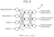
- FIG. 8 is an explanatory diagram showing a configuration example of the parameter determination function PF.
- the parameter determination function PF is configured as a neural network having a three-layer structure. Input of the neural network is a value showing a state of the robot 100 .
- the hand position, the hand speed, the force, and the torque are used as input.
- “Hand position” refers to the position and the attitude of the control point TCP shown in FIG. 1
- hand speed refers to a speed of the control point TCP.
- Force and “torque” are values measured by the force sensor 140 .
- Input to the parameter determination function PF is also referred to as “state observation value”.
- Output of the parameter determination function PF is the virtual mass coefficient M, the virtual viscosity coefficient B, and the virtual elastic coefficient K. Note that, as the input and the output, other items than those may be used. Further, the number of neuron layers is not limited to three, but may be four or more. Furthermore, the parameter determination function PF may be realized by another configuration than the neural network.
- calculation in the respective nodes of the neural network is weighted addition using a weight w L ij .
- L is an ordinal number showing the order of the layer
- i is an ordinal number showing the order of the node of the lower layer
- j is an ordinal number showing the order of the node of the upper layer.
- the parameter search unit 314 executes the optimization with the weight vector W as a search object using the optimization algorithm.
- the weight vector W is referred to as “internal parameter W”.
- FIG. 9 is a flowchart showing a detailed procedure of optimal value search processing in the second embodiment.
- steps S 220 , S 230 , S 240 , S 260 in FIG. 4 are replaced by steps S 225 , S 235 , S 245 , S 265 , and the other steps are substantially the same as those of the first embodiment.
- the procedure of the entire setting processing of the force control parameter shown in FIG. 3 are the same as that of the first embodiment.
- the parameter search unit 314 searches for a candidate value of the internal parameter W of the parameter determination function PF.
- the searching is also executed using the optimization algorithm such as CMA-ES. Note that, when step S 225 is first executed, a preset initial value is used as the candidate value of the internal parameter W.
- the parameter search unit 314 sets the candidate value of the internal parameter W selected at step S 225 in the parameter determination function PF.
- the operation execution unit 312 implements work of the robot 100 according to the robot control program RP.
- FIG. 10 is a flowchart showing a detailed procedure of implementation of work at step S 245 .
- the parameter search unit 314 acquires a state observation value of the robot 100 .
- the state observation value of the robot 100 is a value as input of the parameter determination function PF shown in FIG. 8 .
- the state observation value is acquired by observation of the state of the robot 100 using sensors including the force sensor 140 and the arm encoder 122 .
- the parameter search unit 314 determines the candidate value of the force control parameter using the parameter determination function PF.
- the state observation value acquired at step S 410 is used as the input of the parameter determination function PF.
- the internal parameter W of the parameter determination function PF is set at step S 235 in FIG. 9 .
- step S 430 the operation execution unit 312 executes work including force control operation. This work is continued until the work is determined as being finished at step S 440 . When the work is not finished, the process goes to step S 450 , which will be described later. On the other hand, when the work is finished, the process goes to step S 460 and a measurement result containing the measurement values of the sensors and the takt time of the work is recorded.
- the parameter search unit 314 determines whether or not a preset update time elapses. “Update time” refers to a time suitable for updating of the candidate value of the force control parameter. When the update time does not elapse, the work at step S 440 is continued. On the other hand, when the update time elapses, the process returns to step S 410 and the processing at the above described step S 410 and subsequent steps is executed again.
- a determination criterion whether or not a preset update condition is fulfilled may be used. In this regard, in the middle of single work, steps S 410 to S 430 are repeated at each time when the update condition is fulfilled.
- a fixed update time may be used as shown in FIG. 10 , or a condition whether or not a single work portion as part of the work is finished may be used instead. For example, when the entire work contains a work portion using force control and a work portion not using the force control, whether or not those individual work portions are finished may be used as the determination criterion at step S 450 . For example, regarding the work to fit the first workpiece W 1 in the second workpiece W 2 in FIG. 1 , whether or not the following five work portions are respectively finished may be used as determination criteria:
- the state observation value at a specific time may be used. For example, in the past trial in which the optimal value of the force control parameter is obtained with respect to the work portions executed next at step S 430 , the state observation value at the time when the maximum resultant force f peak is obtained may be acquired from the memory 320 at step S 410 . In this manner, the candidate value of the force control parameter may be determined by the parameter determination function PF using the state observation value suitable for the work portion. Note that, when step S 410 is first executed, a predetermined initial value is used as the state observation value.
- step S 450 may be omitted and, when the work is determined as being not finished at step S 440 , the process may be returned to step S 430 .
- the candidate value of the force control parameter is maintained at the same value through the entire work.
- the state observation value at step S 410 of the history of the state observation values in the past trials of the work, the state observation value at a specific time may be used. For example, in the past trial of the work in which the optimal value of the force control parameter is obtained, the state observation value at the time when the maximum resultant force f peak is obtained may be acquired from the memory 320 at step S 410 . Note that, when step S 410 is first executed, a predetermined initial value is used as the state observation value.
- step S 460 a measurement result containing the measurement values of the sensors and the takt time of the work is recorded. Note that, when the candidate value of the force control parameter is updated in the middle of the work, the history of the candidate values of the force control parameter is also recorded. In this regard, the history of the state observation values may be recorded.
- the processing at step S 250 in FIG. 9 is the same as that of the first embodiment, and the parameter search unit 314 calculates a value of the objective function in the optimization processing from the measurement result obtained during the work.
- the parameter search unit 314 confirms the optimal values of the force control parameter and the internal parameter according to the value of the objective function y. That is, when the value of the objective function y is the minimum value of the previous values, this candidate value is updated as a new optimal value. On the other hand, when the value of the objective function y is not the minimum value of the previous values, the previous optimal value is maintained without change.
- the processing at step S 270 and the subsequent steps is the same as that of the first embodiment and the explanation thereof will be omitted.
- the candidate value of the internal parameter W of the parameter determination function PF is searched for according to the optimization algorithm using the objective function y. Further, the state of the robot 100 is observed during the implementation of the work and the state observation value is input to the parameter determination function PF and the candidate value of the force control parameter is obtained, and the force control operation is executed using the force control parameter.
- the force control parameter may be adaptively determined according to the state of the robot 100 , and an appropriate force control parameter can be used with respect to each stage of the work.
- the objective function in the form in which the penalty increasing according to the exceedance of the specific force control characteristic value from the allowable value is added to the actual measurement value of the evaluation item is used, and the force control parameter may be optimized while the possibility that the value is larger than the limit value as the constraint condition may be reduced. Further, even when the force sensor has output variations, the possibility that the force control characteristic value is larger than the limit value as the constraint condition may be reduced.
- the present disclosure is not limited to the above described embodiments, but may be realized in various aspects without departing from the scope thereof.
- the present disclosure can be realized in the following aspects.
- the technical features in the above described embodiments corresponding to the technical features in the following respective aspects can be appropriately replaced or combined for solving part or all of the problems of the present disclosure or achieving part or all of the effects of the present disclosure.
- the technical features not described as essential features in this specification can be appropriately deleted.
- a method of setting a force control parameter in work of a robot includes (a) setting a limit value specifying a constraint condition with respect to a specific force control characteristic value detected in force control and an objective function with respect to a specific evaluation item relating to the work, (b) searching for an optimal value of the force control parameter using the objective function, and (c) determining a setting value of the force control parameter according to a result of the searching.
- the objective function has a form in which a penalty increasing according to an exceedance of the force control characteristic value from an allowable value smaller than the limit value is added to an actual measurement value of the evaluation item.
- the objective function used for optimization of the force control parameter the objective function in the form in which the penalty increasing according to the exceedance of the force control characteristic value from the allowable value is added to the actual measurement value of the evaluation item is used, and the force control parameter may be optimized while the possibility that the value is larger than the limit value as the constraint condition may be reduced. Further, even when the force sensor has output variations, the possibility that the force control characteristic value is larger than the limit value as the constraint condition may be reduced.
- the penalty of the objective function may contain a first penalty component obtained by multiplication of the exceedance of the force control characteristic value from the allowable value by a first increase rate and a second penalty component obtained by multiplication of an exceedance of the force control characteristic value from the limit value by a second increase rate.
- the larger penalty is given to the exceedance from the limit value, and thereby, the possibility that value is larger than the limit value at optimization may be reduced.
- (b) may include (b1) trying the work by the robot at a plurality of times with the value of the force control parameter maintained and measuring the force control characteristic value at the respective trials, (b2) updating the objective function according to measurement values of the force control characteristic values in the plurality of trials, and (b3) executing the searching of the optimal value using the updated objective function, and (b2) may include obtaining a standard deviation of the force control characteristic values in the plurality of trials, and updating the allowable value to equalize a difference between the allowable value and the limit value to a difference value having a positive correlation with the standard deviation.
- an appropriate allowable value may be set according to the variation of the force control characteristic value.
- (b2) may further include obtaining an average value of the force control characteristic values in the plurality of trials, and increasing the first increase rate when the average value is larger by a first determination value or more than the allowable value, and decreasing the first increase rate when the average value is smaller by a second determination value or more than the allowable value.
- the first increase rate may be adjusted so that the force control characteristic value measured during the work may fall within a range close to the allowable value.
- (b) may include (i) searching for a candidate value of an internal parameter of a parameter determination function to which a state observation value showing a state of the robot is input and from which the force control parameter is output according to an optimization algorithm using the objective function, (ii) setting the candidate value of the internal parameter obtained at (i) in the parameter determination function, (iii) acquiring the state observation value, (iv) obtaining a candidate value of the force control parameter by inputting the state observation value to the parameter determination function, (v) acquiring a measurement result containing the force control characteristic value and the evaluation item by executing the work of the robot using the candidate value of the force control parameter, (vi) calculating a value of the objective function from the measurement result, and (vii) repeating (i) to (vi) until a search end condition is fulfilled.
- the evaluation item may be a takt time of the work
- the force control characteristic value may contain at least one of a maximum value of a resultant force and a maximum value of resultant moment applied to a workpiece as an object of the work from the robot
- the force control parameter may contain at least one of a virtual mass coefficient, a virtual viscosity coefficient, and a virtual elastic coefficient.
- optimization with respect to at least one of the virtual mass coefficient, the virtual viscosity coefficient, and the virtual elastic coefficient may be executed using the objective function in the form in which the penalty according to the maximum value of the resultant force or the resultant moment is added to the actual measurement value of the takt time.
- a robot system includes a robot, a sensor detecting a specific force control characteristic value in work of the robot by force control, and a parameter setting section executing processing of setting a force control parameter of the robot.
- the parameter setting section executes (a) processing of setting a limit value specifying a constraint condition with respect to the force control characteristic value and an objective function with respect to a specific evaluation item relating to the work, (b) processing of searching for an optimal value of the force control parameter using the objective function, and (c) processing of determining a setting value of the force control parameter according to a result of the searching.
- the objective function has a form in which a penalty increasing according to an exceedance of the force control characteristic value from an allowable value smaller than the limit value is added to an actual measurement value of the evaluation item.
- a non-transitory computer-readable storage medium storing a computer program controlling a processor to execute processing of setting a force control parameter in work of a robot.
- the computer program controls the processor to execute (a) processing of setting a limit value specifying a constraint condition with respect to a specific force control characteristic value detected in force control and an objective function with respect to a specific evaluation item relating to the work, (b) processing of searching for an optimal value of the force control parameter using the objective function, and (c) processing of determining a setting value of the force control parameter according to a result of the searching.
- the objective function has a form in which a penalty increasing according to an exceedance of the force control characteristic value from an allowable value smaller than the limit value is added to an actual measurement value of the evaluation item.
- the present disclosure can be realized in various other aspects than those described above.
- the present disclosure may be realized in aspects such as a robot system including a robot and a robot control apparatus, a computer program for realizing functions of the robot control apparatus, and a non-transitory storage medium recording the computer program.
Landscapes
- Engineering & Computer Science (AREA)
- Robotics (AREA)
- Mechanical Engineering (AREA)
- Manipulator (AREA)
- Feedback Control In General (AREA)
Abstract
Description
y=t+G(f peak) (1)
G(f peak)=0 (when f peak ≤F 1) (2a)
G(f peak)=θ1(f peak −F 1) (when F 1 <f peak ≤F 2) (2b)
G(f peak)=θ1(f peak −F 1)+θ2(f peak −F 2) (when f peak >F 2) (2c)
F 1 =F 2 −k 1×σ (3)
-
- (1) move the
end effector 150 to above the first workpiece W1, and then, move the end effector downward to the position of the first workpiece W1; - (2) grip the first workpiece W1 by the
end effector 150; - (3) move the gripped first workpiece W1 to above the second workpiece W2, and then, move the first workpiece downward to immediately above the second workpiece W2;
- (4) fit the first workpiece W1 in the second workpiece W2; and
- (5) release the first workpiece W1 and move the
end effector 150 to above.
- (1) move the
-
- (a) when fN≥F1+m1, increase θ1 with θ1=θ1+a
- (b) when fN≤F1−m2, decrease θ1 with θ1=θ1−a
-
- (a) when P1≤P, increase θ2 with θ2=θ2+b
- (b) when P≤P2, decrease θ2 with θ2=θ2−b
-
- (1) Move the
end effector 150 to above the first workpiece W1, and then, move the end effector downward to the position of the first workpiece W1. - (2) Grip the first workpiece W1 by the
end effector 150. - (3) Move the gripped first workpiece W1 to above the second workpiece W2, and then, move the first work piece downward to immediately above the second workpiece W2.
- (4) Fit the first workpiece W1 in the second workpiece W2.
- (5) Release the first workpiece W1 and move the
end effector 150 to above.
- (1) Move the
Claims (9)
Applications Claiming Priority (2)
| Application Number | Priority Date | Filing Date | Title |
|---|---|---|---|
| JP2021106232A JP2023004513A (en) | 2021-06-28 | 2021-06-28 | Method for setting force control parameter in robot work, robot system, and computer program |
| JP2021-106232 | 2021-06-28 |
Publications (2)
| Publication Number | Publication Date |
|---|---|
| US20220410386A1 US20220410386A1 (en) | 2022-12-29 |
| US12179357B2 true US12179357B2 (en) | 2024-12-31 |
Family
ID=84543550
Family Applications (1)
| Application Number | Title | Priority Date | Filing Date |
|---|---|---|---|
| US17/850,046 Active 2043-03-04 US12179357B2 (en) | 2021-06-28 | 2022-06-27 | Method of setting force control parameter in work of robot, robot system, and computer program |
Country Status (3)
| Country | Link |
|---|---|
| US (1) | US12179357B2 (en) |
| JP (1) | JP2023004513A (en) |
| CN (1) | CN115592661B (en) |
Families Citing this family (3)
| Publication number | Priority date | Publication date | Assignee | Title |
|---|---|---|---|---|
| JP2023004513A (en) * | 2021-06-28 | 2023-01-17 | セイコーエプソン株式会社 | Method for setting force control parameter in robot work, robot system, and computer program |
| CN116577583B (en) * | 2023-05-17 | 2023-11-28 | 国能龙源环保有限公司 | Electrical parameter evaluation method and device for desulfurization system and electronic equipment |
| CN118857730B (en) * | 2024-07-31 | 2026-02-06 | 东风商用车有限公司 | Robot operation endurance test monitoring method, device, equipment and storage medium |
Citations (9)
| Publication number | Priority date | Publication date | Assignee | Title |
|---|---|---|---|---|
| US20110093120A1 (en) * | 2009-10-20 | 2011-04-21 | Kabushiki Kaisha Yaskawa Denki | Apparatus and method for adjusting parameter of impedance control |
| US9723144B1 (en) * | 2016-09-20 | 2017-08-01 | Noble Systems Corporation | Utilizing predictive models to improve predictive dialer pacing capabilities |
| US20190314996A1 (en) * | 2018-02-09 | 2019-10-17 | Fanuc Corporation | Control device and machine learning device |
| US20200101603A1 (en) | 2018-10-02 | 2020-04-02 | Fanuc Corporation | Controller and control system |
| JP2020055095A (en) | 2018-10-02 | 2020-04-09 | ファナック株式会社 | Control device and control system |
| US20200164514A1 (en) * | 2018-11-28 | 2020-05-28 | Kabushiki Kaisha Toshiba | Robot motion planning device, robotic system, and method |
| US20210370507A1 (en) * | 2020-05-29 | 2021-12-02 | Mitsubishi Electric Research Laboratories, Inc. | Apparatus and Method for Planning Contact-Interaction Trajectories |
| US11205124B1 (en) * | 2020-12-04 | 2021-12-21 | East China Jiaotong University | Method and system for controlling heavy-haul train based on reinforcement learning |
| US20220219320A1 (en) * | 2019-05-29 | 2022-07-14 | Universal Robots A/S | Detection of change in contact between robot arm and an object |
Family Cites Families (6)
| Publication number | Priority date | Publication date | Assignee | Title |
|---|---|---|---|---|
| JP2000148224A (en) * | 1998-11-11 | 2000-05-26 | Meidensha Corp | Controller for machining robot |
| CN102588211B (en) * | 2012-02-29 | 2013-08-14 | 沈阳华人风电科技有限公司 | Model prediction control method and model prediction control system for all working conditions of wind generating set |
| WO2013130956A1 (en) * | 2012-03-02 | 2013-09-06 | Vigilent Corporation | Multi-dimensional optimization for controlling environmental maintenance modules |
| WO2015049823A1 (en) * | 2013-10-04 | 2015-04-09 | 本田技研工業株式会社 | Accelerator pedal counterforce control device |
| JP2023004513A (en) * | 2021-06-28 | 2023-01-17 | セイコーエプソン株式会社 | Method for setting force control parameter in robot work, robot system, and computer program |
| JP2023042678A (en) * | 2021-09-15 | 2023-03-28 | セイコーエプソン株式会社 | Methods, robot systems, and computer programs for adjusting force control parameters for force-controlled motion of robots |
-
2021
- 2021-06-28 JP JP2021106232A patent/JP2023004513A/en active Pending
-
2022
- 2022-06-24 CN CN202210723911.1A patent/CN115592661B/en active Active
- 2022-06-27 US US17/850,046 patent/US12179357B2/en active Active
Patent Citations (9)
| Publication number | Priority date | Publication date | Assignee | Title |
|---|---|---|---|---|
| US20110093120A1 (en) * | 2009-10-20 | 2011-04-21 | Kabushiki Kaisha Yaskawa Denki | Apparatus and method for adjusting parameter of impedance control |
| US9723144B1 (en) * | 2016-09-20 | 2017-08-01 | Noble Systems Corporation | Utilizing predictive models to improve predictive dialer pacing capabilities |
| US20190314996A1 (en) * | 2018-02-09 | 2019-10-17 | Fanuc Corporation | Control device and machine learning device |
| US20200101603A1 (en) | 2018-10-02 | 2020-04-02 | Fanuc Corporation | Controller and control system |
| JP2020055095A (en) | 2018-10-02 | 2020-04-09 | ファナック株式会社 | Control device and control system |
| US20200164514A1 (en) * | 2018-11-28 | 2020-05-28 | Kabushiki Kaisha Toshiba | Robot motion planning device, robotic system, and method |
| US20220219320A1 (en) * | 2019-05-29 | 2022-07-14 | Universal Robots A/S | Detection of change in contact between robot arm and an object |
| US20210370507A1 (en) * | 2020-05-29 | 2021-12-02 | Mitsubishi Electric Research Laboratories, Inc. | Apparatus and Method for Planning Contact-Interaction Trajectories |
| US11205124B1 (en) * | 2020-12-04 | 2021-12-21 | East China Jiaotong University | Method and system for controlling heavy-haul train based on reinforcement learning |
Also Published As
| Publication number | Publication date |
|---|---|
| JP2023004513A (en) | 2023-01-17 |
| CN115592661B (en) | 2025-06-17 |
| CN115592661A (en) | 2023-01-13 |
| US20220410386A1 (en) | 2022-12-29 |
Similar Documents
| Publication | Publication Date | Title |
|---|---|---|
| US12179357B2 (en) | Method of setting force control parameter in work of robot, robot system, and computer program | |
| JP6542839B2 (en) | Control device and machine learning device | |
| US10953538B2 (en) | Control device and learning device | |
| US10807234B2 (en) | Component supply device and machine learning device | |
| US10940585B2 (en) | Vibration suppression device | |
| US20100114807A1 (en) | Reinforcement learning system | |
| JP2019093461A (en) | Holding system, learning device, holding method and model manufacturing method | |
| US12275150B2 (en) | Method of setting control parameter of robot, robot system, and computer program | |
| US10549422B2 (en) | Robot controller, machine learning device and machine learning method | |
| CN115533916B (en) | A method, system, device and medium for identifying load mass at the end of a robotic arm | |
| KR20110048870A (en) | Load Estimation Method for 4-Axis Palletizing Robot | |
| JP2023018765A (en) | Anomaly Detection System for Detecting Abnormality in Robot, Method for Detecting Abnormality in Robot, and Computer Program | |
| US11839978B2 (en) | Method of adjusting force control parameter | |
| CN120921336A (en) | Teaching method and system for zero-force dragging of robot | |
| JP2001092511A (en) | Control gain adjustment device for robots | |
| CN111984000A (en) | Method and apparatus for automatically influencing an actuator | |
| Galicki | Robust task space trajectory tracking control of robotic manipulators | |
| EP3610993B1 (en) | System for active motion displacement control of a robot | |
| JP2023042678A (en) | Methods, robot systems, and computer programs for adjusting force control parameters for force-controlled motion of robots | |
| JP2023022386A (en) | Motion parameter adjustment method, motion parameter adjustment device, and computer program for adjusting motion parameters of robot | |
| US12145274B2 (en) | Operation parameter adjusting method and operation parameter adjusting device for adjusting operation parameters of robot | |
| CN121083647B (en) | Data Acquisition Methods and Equipment for Humanoid Robot Training Grounds | |
| JP7576891B1 (en) | Control device, control method, and program | |
| CN121928564A (en) | Self-adaptive grabbing control method and system for robot | |
| JP2020121358A (en) | Learning control device, robot control device and robot |
Legal Events
| Date | Code | Title | Description |
|---|---|---|---|
| AS | Assignment |
Owner name: SEIKO EPSON CORPORATION, JAPAN Free format text: ASSIGNMENT OF ASSIGNORS INTEREST;ASSIGNORS:MIZOBE, KIMITAKE;TODA, JUN;FUKUSEN, TAKAHISA;SIGNING DATES FROM 20220329 TO 20220609;REEL/FRAME:060319/0727 |
|
| FEPP | Fee payment procedure |
Free format text: ENTITY STATUS SET TO UNDISCOUNTED (ORIGINAL EVENT CODE: BIG.); ENTITY STATUS OF PATENT OWNER: LARGE ENTITY |
|
| STPP | Information on status: patent application and granting procedure in general |
Free format text: DOCKETED NEW CASE - READY FOR EXAMINATION |
|
| STPP | Information on status: patent application and granting procedure in general |
Free format text: NON FINAL ACTION MAILED |
|
| STPP | Information on status: patent application and granting procedure in general |
Free format text: RESPONSE TO NON-FINAL OFFICE ACTION ENTERED AND FORWARDED TO EXAMINER |
|
| STPP | Information on status: patent application and granting procedure in general |
Free format text: NOTICE OF ALLOWANCE MAILED -- APPLICATION RECEIVED IN OFFICE OF PUBLICATIONS |
|
| STPP | Information on status: patent application and granting procedure in general |
Free format text: PUBLICATIONS -- ISSUE FEE PAYMENT VERIFIED |
|
| STCF | Information on status: patent grant |
Free format text: PATENTED CASE |