US12176597B2 - Grip and traction enhancement component in a bracket for mounting an antenna alignment device to an antenna - Google Patents
Grip and traction enhancement component in a bracket for mounting an antenna alignment device to an antenna Download PDFInfo
- Publication number
- US12176597B2 US12176597B2 US18/054,011 US202218054011A US12176597B2 US 12176597 B2 US12176597 B2 US 12176597B2 US 202218054011 A US202218054011 A US 202218054011A US 12176597 B2 US12176597 B2 US 12176597B2
- Authority
- US
- United States
- Prior art keywords
- antenna
- mounting bracket
- piece
- abutment pad
- abutment
- Prior art date
- Legal status (The legal status is an assumption and is not a legal conclusion. Google has not performed a legal analysis and makes no representation as to the accuracy of the status listed.)
- Active, expires
Links
Images


Classifications
-
- H—ELECTRICITY
- H01—ELECTRIC ELEMENTS
- H01Q—ANTENNAS, i.e. RADIO AERIALS
- H01Q1/00—Details of, or arrangements associated with, antennas
- H01Q1/12—Supports; Mounting means
- H01Q1/1207—Supports; Mounting means for fastening a rigid aerial element
- H01Q1/1228—Supports; Mounting means for fastening a rigid aerial element on a boom
-
- H—ELECTRICITY
- H01—ELECTRIC ELEMENTS
- H01Q—ANTENNAS, i.e. RADIO AERIALS
- H01Q1/00—Details of, or arrangements associated with, antennas
- H01Q1/12—Supports; Mounting means
- H01Q1/1207—Supports; Mounting means for fastening a rigid aerial element
- H01Q1/1221—Supports; Mounting means for fastening a rigid aerial element onto a wall
-
- H—ELECTRICITY
- H01—ELECTRIC ELEMENTS
- H01Q—ANTENNAS, i.e. RADIO AERIALS
- H01Q1/00—Details of, or arrangements associated with, antennas
- H01Q1/12—Supports; Mounting means
- H01Q1/125—Means for positioning
-
- H—ELECTRICITY
- H01—ELECTRIC ELEMENTS
- H01Q—ANTENNAS, i.e. RADIO AERIALS
- H01Q7/00—Loop antennas with a substantially uniform current distribution around the loop and having a directional radiation pattern in a plane perpendicular to the plane of the loop
Definitions
- antennas receive fluctuating electrical currents through wires from connected circuitry and generate wireless signals as electromagnetic fields corresponding to the fluctuating electrical currents.
- antennas convert electromagnetic fields of the received wireless signals to electrical currents carried through wires to the connected circuitry. Because of directional oscillation of electrical and magnetic fields, wireless signaling through transmittal and receipt of electromagnetic fields is inherently directional: heavily influenced by the location of the signal source, multipathing, beamforming, and or other aspects associated with electromagnetic fields and electromagnetic radiation. Antenna alignment may therefore be desired for optimizing bandwidth, signal strength, and or other transmit/receive parameters. Antenna alignment may generally be performed using antenna alignment devices.
- the antenna alignment devices are coupled to the antenna using mounting brackets.
- a mounting bracket for example, has a first set of bracket components to receive an antenna alignment device and a second set of bracket components to attach to the antenna.
- different types of mounting brackets have been used.
- brackets While conventional mounting brackets have worked for conventional antennas such as those made of fiberglass, there has been an increasing trend of using soft side antennas, i.e., antennas made of plastic with higher degree of flexibility; and the use of conventional mounting brackets in the soft side antennas creates several technical challenges.
- the bracket components that attach to the antenna are rigid and have a smaller surface area, thereby creating a high-pressure region on the attachment surface when a clamping force is applied.
- Such high-pressure region may deform the soft side antenna, generally by disturbing the planar and or perpendicular orientation of the antenna, or even causing damage to the surface of the antenna.
- the conventional mounting brackets are susceptible to slippage, e.g., when the antenna is wet and or has moss on its surface. During these conditions, it becomes very difficult for a technician to mount an antenna alignment device to the antenna and stably maintain the coupling throughout the antenna alignment process.
- a bracket component (referred to herein as an abutment pad) that abuts an antenna is provided.
- the bracket component has a relatively large surface area for a wider distribution of the applied clamping force, thereby minimizing high-pressure regions.
- the bracket component is made of a first piece and a second piece.
- the first piece is made of soft material such as rubber that abuts and grips an exterior surface of the antenna, thereby minimizing the slippage problem when the antenna surface is wet and or mossy.
- the second piece is made of rigid material such as metal or a metal alloy (e.g., an aluminum alloy) to maintain the structural integrity of the bracket component.
- a mounting bracket configured to mount an antenna alignment device to an antenna.
- the mounting bracket may comprise an abutment pad configured to abut an external surface of the antenna, the abutment pad comprising a first piece and a second piece.
- the first piece may comprise a relatively soft material configured to have a traction with the external surface of the antenna.
- the second piece may comprise a relatively hard material configured to provide structural integrity to the abutment pad.
- the abutment pad is configured to provide a relatively larger abutting surface area between the mounting bracket and the external surface of the antenna.
- a method of mounting an antenna alignment device to an antenna may comprise attaching the antenna alignment device to a mounting bracket.
- the method may also comprise attaching the mounting bracket to the antenna, the attaching comprising: abutting an abutment pad of the mounting bracket to an external surface of the antenna, the abutment pad comprising a first piece and a second piece, the first piece comprising a relatively soft material having a traction with the external surface of the antenna, the second piece comprising a relatively hard material providing structural integrity to the abutment pad, and the abutment pad providing a relatively larger abutting surface area between the mounting bracket and the external surface of the antenna.
- FIGS. 1 A- 1 D show several views of an example antenna alignment environment, based on the principles disclosed herein.
- FIGS. 2 A- 2 F show several views of an example coupling between an antenna alignment device and a mounting bracket within the antenna alignment environment shown in FIGS. 1 A- 1 D , based on the principles disclosed herein, based on the principles disclosed herein.
- FIGS. 3 A- 3 C show several views of a bracket component within the mounting bracket shown in FIGS. 2 A- 2 F , based on the principles disclosed herein.
- FIG. 4 shows a flow diagram of mounting an antenna alignment device to an antenna, based on the principles disclosed herein.
- a significant improvement for mounting brackets for mounting an antenna alignment is desired, particularly for soft side antennas and for handling slippery conditions when e.g., an antenna is wet and or mossy.
- Conventional mounting brackets have several technical shortcomings: for example, they create high pressure regions that disturb the planar and or perpendicular alignment of the antenna or even cause damage to the antenna; they further cannot maintain—due to slippage—a stable mount during e.g., wet and or mossy conditions.
- One or more embodiments disclosed herein significantly improve the mounting brackets used with antenna alignment devices.
- an abutment pad (generally referred to herein as a bracket component) is formed using a first piece with a relatively soft material such as rubber to abut the antenna surface and a second piece with a relatively hard material such as metal or a metal alloy.
- the relatively soft material can be further textured or patterned to enhance the grip of the abutment pad to the antenna surface.
- the relatively hard material maintains the structural integrity of the abutment pad.
- the abutment pad may have a relatively larger size to distribute the clamping force and avoid high-pressure regions, thereby minimizing the likelihood of disturbing the orientation of the antenna and minimizing the likelihood of deforming the antenna.
- the abutment pad may further have a fastening mechanism comprising e.g., multiple screw holes such that the abutment pad may be adjustably fastened to the mounting bracket in accordance with the disclosed principles.
- FIGS. 1 A- 1 D show several views of an example antenna alignment environment 100 (also referred to as antenna tuning environment), based on the principles disclosed herein. Particularly, FIG. 1 A shows a front perspective view, FIG. 1 B shows a back perspective view, FIG. 10 shows a back view, and FIG. 1 D shows a top view of the environment 100 .
- the antenna alignment environment 100 generally includes an antenna alignment device 102 mounted to an antenna 104 using a mounting bracket 108 .
- the antenna 104 itself may be disposed on a pole and or any other supporting structure (not shown).
- the antenna 104 may be located on any type of structure such as an antenna tower, rooftop, treetop, building wall, vehicle top, satellite, and or any other type of structure.
- the antenna 104 can be any type of antenna, including a dome antenna, loop antenna, Yagi-type antenna, and or any type of antenna that may have to be aligned for optimal performance.
- the antenna 104 is described herein as a singular antenna, a combination of antennas (including active antenna arrays) that may have to be aligned should also be considered within the scope of this disclosure.
- the antenna 104 may use any kind of transmit/receive frequency, e.g., the antenna 104 may be a microwave antenna used in a cellular communications tower.
- the antenna alignment device 102 may include any type of device that is used to align (or tune) the antenna 104 .
- the antenna alignment device 102 may be formed using any type of cameras, sensors, displays, voltmeters, and or other components configured to align the antenna 104 .
- the orientation of the antenna alignment device 102 may correspond to the orientation of the antenna 104 .
- the alignment may include parameters such as roll, pitch (also referred to as tilt), and or azimuth; as understood in the art.
- the mounting bracket 108 may include any type of components that mount the antenna alignment device 102 to the antenna 104 .
- a first set of bracket components may attach to the antenna alignment device 102 and a second set of bracket components may attach to the antenna 104 thereby creating a coupling between the antenna alignment device 102 and the antenna 104 .
- An example bracket component (specifically referred to as abutment pad), based on the embodiments disclosed herein, is labeled as 110 throughout the Figures.
- the abutment pad 110 as shown in more detail in FIGS. 3 A- 3 C , comprises a relatively soft first piece to abut to the antenna 104 and a relatively hard second piece to maintain the structural integrity of the abutment pad 110 .
- the abutment pad 110 may be adjustably attached to a bracket component 120 (e.g., an angled piece) of the mounting bracket 108 , e.g., using screws (as shown in FIG. 2 F , screws 140 passing through the screw holes 116 ).
- the clamping or tightening force may be applied on the mounting bracket 108 using, e.g., a ratchet mechanism 130 .
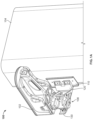
- FIGS. 2 A- 2 F show several views of an example coupling between the antenna alignment device 102 and the mounting bracket 108 bracket within the antenna alignment environment 100 shown in FIGS. 1 A- 1 D , based on the principles disclosed herein. Particularly, FIG. 2 A shows a front perspective view, FIG. 2 B shows a back perspective view, FIG. 2 C shows a back view, FIG. 2 D shows a top view, FIG. 2 E shows a side perspective view, and FIG. 2 F shows a side view of the coupling. As shown, the mounting bracket 108 includes the abutment pad 110 that is configured to abut an antenna (e.g., as shown in the example environment 100 ).
- the abutment pad 110 may be adjustably attached to a bracket component 120 (e.g., an angled piece) of the mounting bracket 108 , e.g., using screws (as shown in FIG. 2 F , screws 140 passing through the holes 116 ).
- the clamping or tightening force may be applied on the mounting bracket 108 using, e.g., a ratchet mechanism 130 .
- FIGS. 3 A- 3 C show detailed views of the abutment pad 110 based on the principles disclosed herein. Particularly, FIG. 3 A shows a front view, FIG. 3 B shows a side view, and FIG. 3 C shows a top view of the abutment pad 110 .
- the shown form factor is merely an example, and abutment pads with any form factor should be considered within the scope of this disclosure.
- the abutment pad 110 may have a circular shape, an oval shape, or a polygonal shape (e.g., a trapezoid, pentagon, octagon, etc.).
- the abutment pad 110 may be constructed of a second piece 112 and first piece 114 .
- the second piece 112 is made of relatively hard material and the first piece 114 is made of relatively soft material.
- the second piece 112 may be formed of any metal, metal alloy, or metallic material.
- the second piece 112 may be formed using 5052 aluminum alloy.
- the second piece 112 may have rounded corners 118 to maintain its structural integrity.
- the first piece 114 that directly abuts the antenna 104 may be formed of rubber and or any other type of polymer material.
- the first piece 114 may be textured and or patterned (as shown in FIG. 3 A ) to increase traction and reduce skid between the first piece 114 and the antenna 104 .
- the relatively soft material used for the first piece 114 may further reduce an abrasion of the surface of the antenna 104 .
- the two-piece design is also provided as an example, and abutment components with any number of pieces should also be considered within the scope of this disclosure.
- the abutment pad 110 may further include a fastening mechanism that fastens the abutment pad 110 to the mounting bracket 108 .
- a fastening mechanism that fastens the abutment pad 110 to the mounting bracket 108 .
- screw holes 116 are provided.
- One or more of the provided screw holes 116 may be used to fasten the abutment pad 110 to the mounting bracket 108 . If the fastening needs an adjustment, screws in the screw holes 116 may be removed and alternate screw holes 116 may be used.
- Such flexibility in fastening allows for the abutment pad 110 to be fastened at different points to the mounting bracket 108 .
- the abutment pad 110 may be fastened at any orientation to the mounting bracket 108 . It should however be understood that the use of the screw holes is just an example fastening mechanism and should not be considered limiting. Any other type of mechanical fastening mechanism should also be considered within the scope of this disclosure. Regardless of the type of fastening mechanism, the flexibility in adjustment aids
- the dimensions of the first piece 114 may be 3.175 mm (thickness)*78 mm (width)*190 mm (height); and the dimensions of the second piece 112 may be 3.175 mm (thickness)*94 mm (width)*200 mm (height). These dimensions are for exemplary purposes only and should not be considered limiting. First and second pieces with any suitable dimension should be considered within the scope of this disclosure.
- FIG. 4 shows a flow diagram of an example method 400 of mounting an antenna alignment device to an antenna, based on the principles disclosed herein. It should be understood that the steps of the method 400 are shown as an example of the disclosed principles and should not be considered limiting. Methods with additional, alternative, or fewer number of steps should also be considered within the scope of this disclosure. Furthermore, the shown order of steps are for illustration purposes, and the steps may be performed in any sequence.
- a mounting bracket may be attached to an antenna.
- the attaching may include abutting an abutment pad to an external surface of the antenna.
- the abutment pad may be coupled to the mounting bracket.
- the coupling may be performed using any kind of mechanical fasteners.
- the abutment pad may have a plurality of screw holes, which may be used to screw tighten the abutment pad to the mounting bracket.
- the mounting bracket may be tightened to the antenna.
- the tightening may be through any kind of tightening and or clamping mechanism.
- a ratchet mechanism may be used for the tightening. The tightening increases the frictional force between the antenna and the antenna alignment device thereby maintaining the coupling between them.
- the abutment pad has a relatively larger surface area to distribute the tightening or the clamping force against the external surface of the antenna. This distribution mitigates high-pressure regions thereby minimizing the disturbance in antenna orientation and also minimizing the likelihood of the antenna being damaged or destroyed.
- the abutment pad has a relatively soft first piece abutting with the antenna. The larger surface of this soft first piece provides a better traction for the mounting bracket to have a steady and stable coupling even when the external surface of the antenna is wet and or mossy.
- the abutment pad is adjusted as needed.
- the currently used screws on a first set of screw holes may be unscrewed and used for a second set of holes.
- This adjustment allows an easy sliding of the abutment pad vis-à-vis the other components of the mounting bracket.
- the adjustment also allows the changing of the orientation of the abutment pad vis-à-vis the other components of the mounting bracket.
- the screw based fastening example is just an example and should not be considered limiting. Any kind of adjustable fastening mechanism should be considered within the scope of this disclosure.
- the antenna alignment device may be attached to the mounting bracket. That is, the antenna alignment device may be attached to a first set of components in the mounting bracket, which are configured to receive the antenna alignment device. For example, the antenna alignment device may be screwed to the first set of components.
Landscapes
- Support Of Aerials (AREA)
Abstract
Description
Claims (18)
Priority Applications (1)
| Application Number | Priority Date | Filing Date | Title |
|---|---|---|---|
| US18/054,011 US12176597B2 (en) | 2022-11-09 | 2022-11-09 | Grip and traction enhancement component in a bracket for mounting an antenna alignment device to an antenna |
Applications Claiming Priority (1)
| Application Number | Priority Date | Filing Date | Title |
|---|---|---|---|
| US18/054,011 US12176597B2 (en) | 2022-11-09 | 2022-11-09 | Grip and traction enhancement component in a bracket for mounting an antenna alignment device to an antenna |
Publications (2)
| Publication Number | Publication Date |
|---|---|
| US20240154292A1 US20240154292A1 (en) | 2024-05-09 |
| US12176597B2 true US12176597B2 (en) | 2024-12-24 |
Family
ID=90928226
Family Applications (1)
| Application Number | Title | Priority Date | Filing Date |
|---|---|---|---|
| US18/054,011 Active 2043-02-28 US12176597B2 (en) | 2022-11-09 | 2022-11-09 | Grip and traction enhancement component in a bracket for mounting an antenna alignment device to an antenna |
Country Status (1)
| Country | Link |
|---|---|
| US (1) | US12176597B2 (en) |
Families Citing this family (1)
| Publication number | Priority date | Publication date | Assignee | Title |
|---|---|---|---|---|
| CN117060046A (en) * | 2023-08-31 | 2023-11-14 | 中磊电子(苏州)有限公司 | Antenna frame and related network communication device |
Citations (4)
| Publication number | Priority date | Publication date | Assignee | Title |
|---|---|---|---|---|
| CN211829177U (en) * | 2020-05-18 | 2020-10-30 | 广东金一百科技有限公司 | Communication engineering antenna installing support |
| CN211952094U (en) * | 2020-01-08 | 2020-11-17 | 山东康威通信技术股份有限公司 | A installing support for aerial basic station antenna angle detector |
| WO2021167718A1 (en) * | 2020-02-21 | 2021-08-26 | Commscope Technologies Llc | An improved radome for a base station antenna and a base station antenna using such a radome |
| CN216413245U (en) * | 2021-12-20 | 2022-04-29 | 深圳市天威讯无线技术有限公司 | Double-breakpoint metal frame 4G antenna |
-
2022
- 2022-11-09 US US18/054,011 patent/US12176597B2/en active Active
Patent Citations (4)
| Publication number | Priority date | Publication date | Assignee | Title |
|---|---|---|---|---|
| CN211952094U (en) * | 2020-01-08 | 2020-11-17 | 山东康威通信技术股份有限公司 | A installing support for aerial basic station antenna angle detector |
| WO2021167718A1 (en) * | 2020-02-21 | 2021-08-26 | Commscope Technologies Llc | An improved radome for a base station antenna and a base station antenna using such a radome |
| CN211829177U (en) * | 2020-05-18 | 2020-10-30 | 广东金一百科技有限公司 | Communication engineering antenna installing support |
| CN216413245U (en) * | 2021-12-20 | 2022-04-29 | 深圳市天威讯无线技术有限公司 | Double-breakpoint metal frame 4G antenna |
Also Published As
| Publication number | Publication date |
|---|---|
| US20240154292A1 (en) | 2024-05-09 |
Similar Documents
| Publication | Publication Date | Title |
|---|---|---|
| USRE41816E1 (en) | Dish antenna rotation apparatus | |
| US5835068A (en) | Microwave transceiver/antenna system with adjustable mounting and alignment mechanism | |
| US20210066779A1 (en) | Antenna mounting assembly | |
| US12176597B2 (en) | Grip and traction enhancement component in a bracket for mounting an antenna alignment device to an antenna | |
| US20070241247A1 (en) | Apparatus and method for mounting a satellite dish to a pole | |
| EP1705745B1 (en) | Antenna mount with fine adjustment cam | |
| US6709184B1 (en) | Apparatus for mounting a receiver mast and associated method | |
| EP3419105B1 (en) | Fastening device and associated method | |
| US20240266711A1 (en) | Antenna mount extension bracket with a retention and alignment clip | |
| JP3267628B2 (en) | Microwave terrestrial radio with dovetail mounting structure and reference plane | |
| US11862839B2 (en) | Mount for coupling an antenna alignment device to an antenna with non-planar external surface | |
| US20240250420A1 (en) | Mitigation of intermodulation distortion in antenna monitoring devices | |
| JP3844953B2 (en) | Antenna installation method and antenna installation apparatus | |
| CN211150752U (en) | Antenna boom convenient to adjust | |
| CN217934184U (en) | Angle-adjustable antenna fixing frame | |
| JPS641767Y2 (en) | ||
| US20230116963A1 (en) | Modular antenna and antenna assembly | |
| JP4532160B2 (en) | Indoor antenna | |
| CN221150295U (en) | Support device and antenna device | |
| CN216818620U (en) | Active antenna easy to radiate heat for communication | |
| KR101342011B1 (en) | Panorama glass roof antenna apparatus for vehicle | |
| JP2581714Y2 (en) | Antenna mounting device | |
| US6791503B2 (en) | Reception antenna system | |
| JP2024076936A (en) | Antenna Device | |
| JPH01143505A (en) | Planar antenna |
Legal Events
| Date | Code | Title | Description |
|---|---|---|---|
| FEPP | Fee payment procedure |
Free format text: ENTITY STATUS SET TO UNDISCOUNTED (ORIGINAL EVENT CODE: BIG.); ENTITY STATUS OF PATENT OWNER: LARGE ENTITY |
|
| AS | Assignment |
Owner name: VIAVI SOLUTIONS INC., ARIZONA Free format text: ASSIGNMENT OF ASSIGNORS INTEREST;ASSIGNORS:STELLE, RALEIGH BENTON, IV;WOOLSEY, ADAM;REEL/FRAME:061721/0391 Effective date: 20221108 |
|
| STPP | Information on status: patent application and granting procedure in general |
Free format text: NON FINAL ACTION MAILED |
|
| STPP | Information on status: patent application and granting procedure in general |
Free format text: RESPONSE TO NON-FINAL OFFICE ACTION ENTERED AND FORWARDED TO EXAMINER |
|
| STPP | Information on status: patent application and granting procedure in general |
Free format text: NOTICE OF ALLOWANCE MAILED -- APPLICATION RECEIVED IN OFFICE OF PUBLICATIONS |
|
| STPP | Information on status: patent application and granting procedure in general |
Free format text: PUBLICATIONS -- ISSUE FEE PAYMENT VERIFIED |
|
| STCF | Information on status: patent grant |
Free format text: PATENTED CASE |
|
| AS | Assignment |
Owner name: WELLS FARGO BANK, NATIONAL ASSOCIATION, AS ADMINISTRATIVE AGENT, CALIFORNIA Free format text: SECURITY AGREEMENT;ASSIGNORS:INERTIAL LABS, INC.;VIAVI SOLUTIONS INC.;VIAVI SOLUTIONS LICENSING LLC;REEL/FRAME:073189/0873 Effective date: 20251016 |
|
| AS | Assignment |
Owner name: WELLS FARGO BANK, NATIONAL ASSOCIATION, AS AGENT, CALIFORNIA Free format text: SECURITY INTEREST;ASSIGNORS:VIAVI SOLUTIONS INC.;VIAVI SOLUTIONS LICENSING LLC;INERTIAL LABS, INC.;REEL/FRAME:073571/0137 Effective date: 20251113 |