US12175055B2 - Display method, sample analyzer, and recording medium - Google Patents
Display method, sample analyzer, and recording medium Download PDFInfo
- Publication number
- US12175055B2 US12175055B2 US16/583,311 US201916583311A US12175055B2 US 12175055 B2 US12175055 B2 US 12175055B2 US 201916583311 A US201916583311 A US 201916583311A US 12175055 B2 US12175055 B2 US 12175055B2
- Authority
- US
- United States
- Prior art keywords
- reagent
- reagent information
- icons
- information
- containers
- Prior art date
- Legal status (The legal status is an assumption and is not a legal conclusion. Google has not performed a legal analysis and makes no representation as to the accuracy of the status listed.)
- Active
Links
Images


Classifications
-
- G—PHYSICS
- G06—COMPUTING OR CALCULATING; COUNTING
- G06F—ELECTRIC DIGITAL DATA PROCESSING
- G06F3/00—Input arrangements for transferring data to be processed into a form capable of being handled by the computer; Output arrangements for transferring data from processing unit to output unit, e.g. interface arrangements
- G06F3/01—Input arrangements or combined input and output arrangements for interaction between user and computer
- G06F3/048—Interaction techniques based on graphical user interfaces [GUI]
- G06F3/0481—Interaction techniques based on graphical user interfaces [GUI] based on specific properties of the displayed interaction object or a metaphor-based environment, e.g. interaction with desktop elements like windows or icons, or assisted by a cursor's changing behaviour or appearance
- G06F3/04817—Interaction techniques based on graphical user interfaces [GUI] based on specific properties of the displayed interaction object or a metaphor-based environment, e.g. interaction with desktop elements like windows or icons, or assisted by a cursor's changing behaviour or appearance using icons
-
- G—PHYSICS
- G01—MEASURING; TESTING
- G01N—INVESTIGATING OR ANALYSING MATERIALS BY DETERMINING THEIR CHEMICAL OR PHYSICAL PROPERTIES
- G01N35/00—Automatic analysis not limited to methods or materials provided for in any single one of groups G01N1/00 - G01N33/00; Handling materials therefor
- G01N35/00584—Control arrangements for automatic analysers
-
- G—PHYSICS
- G01—MEASURING; TESTING
- G01N—INVESTIGATING OR ANALYSING MATERIALS BY DETERMINING THEIR CHEMICAL OR PHYSICAL PROPERTIES
- G01N35/00—Automatic analysis not limited to methods or materials provided for in any single one of groups G01N1/00 - G01N33/00; Handling materials therefor
-
- G—PHYSICS
- G01—MEASURING; TESTING
- G01N—INVESTIGATING OR ANALYSING MATERIALS BY DETERMINING THEIR CHEMICAL OR PHYSICAL PROPERTIES
- G01N35/00—Automatic analysis not limited to methods or materials provided for in any single one of groups G01N1/00 - G01N33/00; Handling materials therefor
- G01N35/00584—Control arrangements for automatic analysers
- G01N35/00722—Communications; Identification
- G01N35/00732—Identification of carriers, materials or components in automatic analysers
-
- G—PHYSICS
- G06—COMPUTING OR CALCULATING; COUNTING
- G06F—ELECTRIC DIGITAL DATA PROCESSING
- G06F3/00—Input arrangements for transferring data to be processed into a form capable of being handled by the computer; Output arrangements for transferring data from processing unit to output unit, e.g. interface arrangements
- G06F3/01—Input arrangements or combined input and output arrangements for interaction between user and computer
- G06F3/048—Interaction techniques based on graphical user interfaces [GUI]
- G06F3/0481—Interaction techniques based on graphical user interfaces [GUI] based on specific properties of the displayed interaction object or a metaphor-based environment, e.g. interaction with desktop elements like windows or icons, or assisted by a cursor's changing behaviour or appearance
- G06F3/0482—Interaction with lists of selectable items, e.g. menus
-
- G—PHYSICS
- G06—COMPUTING OR CALCULATING; COUNTING
- G06F—ELECTRIC DIGITAL DATA PROCESSING
- G06F3/00—Input arrangements for transferring data to be processed into a form capable of being handled by the computer; Output arrangements for transferring data from processing unit to output unit, e.g. interface arrangements
- G06F3/01—Input arrangements or combined input and output arrangements for interaction between user and computer
- G06F3/048—Interaction techniques based on graphical user interfaces [GUI]
- G06F3/0484—Interaction techniques based on graphical user interfaces [GUI] for the control of specific functions or operations, e.g. selecting or manipulating an object, an image or a displayed text element, setting a parameter value or selecting a range
-
- G—PHYSICS
- G01—MEASURING; TESTING
- G01N—INVESTIGATING OR ANALYSING MATERIALS BY DETERMINING THEIR CHEMICAL OR PHYSICAL PROPERTIES
- G01N35/00—Automatic analysis not limited to methods or materials provided for in any single one of groups G01N1/00 - G01N33/00; Handling materials therefor
- G01N35/00584—Control arrangements for automatic analysers
- G01N35/00594—Quality control, including calibration or testing of components of the analyser
- G01N35/00613—Quality control
- G01N35/00663—Quality control of consumables
- G01N2035/00673—Quality control of consumables of reagents
-
- G—PHYSICS
- G01—MEASURING; TESTING
- G01N—INVESTIGATING OR ANALYSING MATERIALS BY DETERMINING THEIR CHEMICAL OR PHYSICAL PROPERTIES
- G01N35/00—Automatic analysis not limited to methods or materials provided for in any single one of groups G01N1/00 - G01N33/00; Handling materials therefor
- G01N35/00584—Control arrangements for automatic analysers
- G01N35/00722—Communications; Identification
- G01N35/00732—Identification of carriers, materials or components in automatic analysers
- G01N2035/00792—Type of components bearing the codes, other than sample carriers
- G01N2035/00811—Type of components bearing the codes, other than sample carriers consumable or exchangeable components other than sample carriers, e.g. detectors, flow cells
-
- G—PHYSICS
- G01—MEASURING; TESTING
- G01N—INVESTIGATING OR ANALYSING MATERIALS BY DETERMINING THEIR CHEMICAL OR PHYSICAL PROPERTIES
- G01N35/00—Automatic analysis not limited to methods or materials provided for in any single one of groups G01N1/00 - G01N33/00; Handling materials therefor
- G01N35/00584—Control arrangements for automatic analysers
- G01N35/00722—Communications; Identification
- G01N35/00732—Identification of carriers, materials or components in automatic analysers
- G01N2035/00821—Identification of carriers, materials or components in automatic analysers nature of coded information
- G01N2035/00851—Identification of carriers, materials or components in automatic analysers nature of coded information process control parameters
-
- G—PHYSICS
- G01—MEASURING; TESTING
- G01N—INVESTIGATING OR ANALYSING MATERIALS BY DETERMINING THEIR CHEMICAL OR PHYSICAL PROPERTIES
- G01N35/00—Automatic analysis not limited to methods or materials provided for in any single one of groups G01N1/00 - G01N33/00; Handling materials therefor
- G01N35/00584—Control arrangements for automatic analysers
- G01N35/00722—Communications; Identification
- G01N2035/00891—Displaying information to the operator
- G01N2035/0091—GUI [graphical user interfaces]
-
- G—PHYSICS
- G01—MEASURING; TESTING
- G01N—INVESTIGATING OR ANALYSING MATERIALS BY DETERMINING THEIR CHEMICAL OR PHYSICAL PROPERTIES
- G01N35/00—Automatic analysis not limited to methods or materials provided for in any single one of groups G01N1/00 - G01N33/00; Handling materials therefor
- G01N35/00584—Control arrangements for automatic analysers
- G01N35/00594—Quality control, including calibration or testing of components of the analyser
- G01N35/00613—Quality control
- G01N35/00663—Quality control of consumables
-
- G—PHYSICS
- G01—MEASURING; TESTING
- G01N—INVESTIGATING OR ANALYSING MATERIALS BY DETERMINING THEIR CHEMICAL OR PHYSICAL PROPERTIES
- G01N35/00—Automatic analysis not limited to methods or materials provided for in any single one of groups G01N1/00 - G01N33/00; Handling materials therefor
- G01N35/02—Automatic analysis not limited to methods or materials provided for in any single one of groups G01N1/00 - G01N33/00; Handling materials therefor using a plurality of sample containers moved by a conveyor system past one or more treatment or analysis stations
- G01N35/025—Automatic analysis not limited to methods or materials provided for in any single one of groups G01N1/00 - G01N33/00; Handling materials therefor using a plurality of sample containers moved by a conveyor system past one or more treatment or analysis stations having a carousel or turntable for reaction cells or cuvettes
Definitions
- the disclosure relates a display method in a sample analyzer that analyzes a sample using reagents, and so on.
- a sample analyzer having a function of automatically measuring measurement items set for each of samples.
- a sample analyzer stores, in a housing, expendables such as reagents used for measurement of measurement items and automatically measures predetermined measurement items for each of samples set as analysis targets using these expendables.
- the sample analyzer is capable of automatically performing the following processes (1) to (4) while sequentially replacing the samples set as the analysis targets: (1) a process for dispensing a sample into a cuvette; (2) a process for preparing a measurement specimen by taking out a reagent relevant to a measurement item from a reagent container and mixing the reagent with the sample; (3) a process for performing measurement concerning measurement items; and (4) a process for performing an analysis based on measurement results.
- Such a sample analyzer is very convenient when a large number of samples are continuously analyzed.
- the sample analyzer has to be furnished with expendables such as cuvettes and reagents in amounts sufficient for the number of samples and the number of measurement items before the start of the analysis.
- expendables such as cuvettes and reagents
- the amounts of the expendables stored in the sample analyzer are insufficient, it is likely that the analysis of the samples stops halfway or a failure of the sample analyzer is caused.
- sample analyzer that displays, on a display unit, a display screen including icons representing reagents arranged in the sample analyzer in order that the reagents stored in the sample analyzer are appropriately managed.
- Information such as states of reagents used for an analysis of samples and measurement items is displayed on the display screen.
- Patent Literature 1 discloses a display screen including a reagent arrangement display region A where marks M representing reagents stored in a sample analyzer is displayed and an operation means display region B where operations for the reagent are displayed (see FIG. 24 ).
- the operation means display region B when any one of buttons included in the operation means display region B is selected in a state where the mark M representing any of the reagents is selected from the reagent arrangement display region A, the predetermined operation is performed for the reagent.
- the reagent can be replaced or the reagent can be added anew.
- management of reagents needs complicated and troublesome work, a predetermined operation, and so on. This can be a burden for an operator of the sample analyzer. For example, since the reagents are consumed in different amounts to analyze one sample, it is indispensable to check the residual amounts of the reagents before an analysis start. Further, since expiration dates for use of reagents to be used to analyze samples are different among lots, it is also necessary to appropriately manage the expiration dates for use of the reagents in order to obtain analysis results with high reliability.
- the operator needs to replace or add each of the reagents. If there is a reagent, a residual amount of which is unknown, the operator needs to instruct the sample analyzer to measure the residual amount of the reagent. For reagents of unregistered lots, the operator needs to input information that should be registered such as the expiration date of use for each of the reagents. When reading of barcode information of a reagent container of a reagent fails, the operator needs to instruct the sample analyzer to read the barcode information again or needs to manually input the information.
- One or more aspects have been devised in order to solve the problems described above, and may aim to provide a display method of reducing a burden of an operator who manages reagents of a sample analyzer.
- a display method may be a method used in a sample analyzer comprising holders configured to hold reagent containers of reagents used for an analysis of a sample.
- the display method may include: displaying, on a display unit, icons respectively associated with the holders; receiving selection of icons from the icons displayed on the display unit; and receiving an instruction for a predetermined operation relevant to the selected icons.
- a sample analyzer may include holders configured to hold reagent containers of reagents used for an analysis of a sample; a display unit; an input unit; a controller.
- the controller is configured to: control the display unit to display icons respectively associated with the holders; receive, through the input unit, selection of icons from the icons displayed on the display unit; and receive, through the input unit, an instruction for a predetermined operation relevant to the selected icons.
- a non-transitory computer-readable storage medium stores a program which may be executable by a computer to perform operations including: displaying, on a display unit, icons respectively associated with holders configured to hold reagent containers of reagents used for an analysis of a sample; receiving selection of icons from the icons displayed on the display unit; and receiving an instruction for a predetermined operation relevant to the selected icons.
- FIG. 1 is a block diagram illustrating a main part configuration of a sample analyzer according to an embodiment
- FIG. 2 is a diagram illustrating a schematically top view of a measuring unit of a sample analyzer according to an embodiment
- FIG. 3 is a block diagram illustrating units related to a display method according to an embodiment
- FIG. 4 is a flow diagram illustrating a sequence of processing in a display method according to an embodiment
- FIG. 5 is a diagram illustrating an example of a configuration of a reagent information database
- FIG. 6 is a diagram illustrating a perspective view of a state where a reagent container is held in a reagent container rack;
- FIG. 7 is a flow diagram illustrating a sequence of processing in a reading step for barcode information
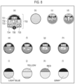
- FIG. 8 is a diagram illustrating examples of reagent information included in icons
- FIG. 9 is a diagram illustrating a table of an example in which reagent information is classified by categories
- FIG. 10 is a diagram illustrating a configuration example of a reagent management screen of a sample analyzer according to an embodiment
- FIG. 11 A , FIG. 11 B and FIG. 11 C are transition diagrams illustrating a display screen in a first embodiment
- FIG. 12 A and FIG. 12 B are transition diagrams illustrating a display screen in a reference example
- FIG. 13 A and FIG. 13 B are transition diagrams illustrating a display screen in a second embodiment
- FIG. 14 A and FIG. 14 B are transition diagrams illustrating a display screen in a third embodiment
- FIG. 15 A , FIG. 15 B and FIG. 15 C are transition diagrams illustrating a display screen in a modification 1;
- FIG. 16 A , FIG. 16 B and FIG. 16 C are transition diagrams illustrating a display screen in a modification 2;
- FIG. 17 A and FIG. 17 B are transition diagrams illustrating a display screen in a modification 3-1;
- FIG. 18 A and FIG. 18 B are transition diagrams illustrating a display screen in a modification 3-2;
- FIG. 19 is a flow diagram illustrating an example of a predetermined operation in a display method according to an embodiment; in this diagram, residual amount measurement for a reagent is adopted as the predetermined operation;
- FIG. 20 is a diagram schematically illustrating a state where height of a liquid surface of a reagent in a reagent container is calculated
- FIG. 21 is a flow diagram illustrating another example of a predetermined operation in a display method according to an embodiment; in this diagram, collective editing of reagent information is adopted as the predetermined operation;
- FIG. 22 is a diagram illustrating an example of a configuration of a reagent information editing region
- FIG. 23 is a flow diagram illustrating still another example of a predetermined operation in a display method according to an embodiment; in this diagram, restoration of reagent information is adopted as the predetermined operation; and
- FIG. 24 is a diagram illustrating a display screen for reagent monitor information in related art.
- a display method in a sample analyzer ( 30 ) including holders ( 441 ) that hold reagent containers ( 442 ) of reagents used for an analysis of a sample, the display method including: a displaying step of displaying, on a display unit ( 33 c ), icons ( 700 ) respectively associated with the holders ( 441 ); a selecting step of receiving selection of icons ( 700 ) from the icons displayed on the display unit ( 33 c ); and an operation receiving step of receiving an instruction for a predetermined operation relevant to the icons ( 700 ) selected in the selecting step.
- the icons ( 700 ) mean icons displayed on, for example, a reagent management screen ( 600 ) of the display unit ( 33 c ) of the sample analyzer ( 30 ).
- Reagent information may be associated with each of the reagents.
- the icons ( 700 ) may be displayed in a form depending on the reagent information.
- the icons ( 700 ) are displayed in a form depending on reagent information of reagents represented by the icons ( 700 ). Therefore, the operator of the sample analyzer ( 30 ) can visually recognize the reagent information by viewing the icons ( 700 ).
- the reagent information means various kinds of information on the reagents.
- the reagent information can also include information on states of the reagents arranged in the holders ( 441 ) included in the sample analyzer ( 30 ).
- the reagent information includes, for example, information for identifying the reagents, information indicating states of the reagents, and information on measurement items of the reagents.
- the reagent containers are sometimes not arranged in the holders ( 441 ). Therefore, the reagent information may include information indicating whether the reagent containers are arranged in the holders ( 441 ).
- the predetermined operation may include (i) measurement of residual amounts of reagents, (ii) editing of reagent information on the reagents, or (iii) acquisition of the reagent information on the reagents.
- the sample analyzer ( 30 ) executes, on the reagents represented by the icons ( 700 ) selected in the selecting step, (i) measurement of residual amounts of the reagents, (ii) editing of reagent information on the reagents, or (iii) acquisition of the reagent information on the reagents. Therefore, the operator of the sample analyzer ( 30 ) can collectively perform, for reagents, (i) measurement of residual amounts of the reagents, (ii) editing of reagent information on the reagents, or (iii) acquisition of the reagent information on the reagents.
- Arrangement of the icons ( 700 ) on a display screen displayed on the display unit ( 33 c ) may correspond to arrangement of the holders ( 441 ) mounted with the reagent containers ( 442 ) indicated by the icons ( 700 ).
- arrangement of the icons ( 700 ) on the display unit ( 33 c ) correspond to arrangement of the reagent containers ( 442 ) in a reagent table ( 440 ). Therefore, the operator of the sample analyzer ( 30 ) can intuitively recognize, on the display screen, actual arrangement of the reagent containers ( 442 ). Operability is further improved.
- a sample analyzer ( 30 ) is a sample analyzer ( 30 ) including: holders configured to hold reagent containers of reagents used for an analysis of a sample; a display unit; an input unit; a controller.
- the controller is configured to: control the display unit to display icons respectively associated with the holders; receive, through the input unit, selection of icons from the icons displayed on the display unit; and receive, through the input unit, an instruction for a predetermined operation relevant to the selected icons.
- the sample analyzer ( 30 ) that can receive the instruction for the predetermined operation relevant to the icons ( 700 ) is provided.
- a non-transitory computer-readable storage medium stores a program which is executable by a computer to perform operations comprising: displaying, on a display unit, icons respectively associated with holders configured to hold reagent containers of reagents used for an analysis of a sample; receiving selection of icons from the icons displayed on the display unit; and receiving an instruction for a predetermined operation relevant to the selected icons.
- the non-transitory computer-readable storage medium storing a program for controlling the sample analyzer ( 30 ) to be able to receive the instruction for the predetermined operation relevant to the icons ( 700 ) is provided.
- a display method of reducing a burden of an operator who manages reagents of a sample analyzer is provided.
- the sample analyzer 30 includes a measuring unit 32 and an analyzing unit 33 .
- the measuring unit 32 includes a measurement controller 32 a , a measurement memory 32 b , and various functional units illustrated in FIG. 2 .
- the measurement controller 32 a is, for example, a CPU.
- the measuring memory 32 b is, for example, a ROM, a RAM, or a hard disk.
- the measurement controller 32 a controls the units in the measuring unit 32 according to programs and data stored in the measurement memory 32 b .
- the measurement controller 32 a performs, for example, measurement necessary for a blood coagulation analysis of a sample and sends a result of the measurement to the analyzing unit 33 .
- the analyzing unit 33 includes an analysis controller 33 a , an analysis memory 33 b , a display unit 33 c , and an input unit 33 d .
- the analysis controller 33 a is, for example, a CPU.
- the analysis memory 33 b is, for example, a ROM, a RAM, or a hard disk.
- the analysis controller 33 a controls the units in the analyzing unit 33 and the measuring unit 32 according to programs and data stored in the analysis memory 33 b .
- the display unit 33 c is, for example, a liquid crystal display.
- the input unit 33 d is, for example, a mouse and a keyboard.
- the display unit 33 c and the input unit 33 d may be integrally configured by, for example, a display of a touch panel type.
- the analysis controller 33 a may be realized by hardware (for example, using a logic circuit formed in an integrated circuit or the like). Alternatively, the analysis controller 33 a may be realized by software (for example, using a device including one or more processors and a computer-readable recording medium storing a program for causing a computer to realize functions).
- the analysis controller 33 a performs, for example, a blood coagulation analysis of a sample based on a measurement result received from the measuring unit 32 .
- the analysis controller 33 a performs an analysis concerning measurement item such as PT, APTT, Fbg, an exogenous coagulation factor, an endogenous coagulation factor, a coagulation XIII-th factor, HpT, TTO, FDP, D dimer, PIC, FM, ATIII, PIg, APL, PC, VWF:Ag, VWF:RCo, ADP, collagen, and epinephrine.
- the measuring unit 32 is arranged behind a transporter 31 .
- the measuring unit 32 performs measurement necessary for the blood coagulation analysis.
- a sample stored in a sample container 20 is plasma.
- liquid stored in the sample container 20 as the sample is not limited to the plasma. That is, the sample stored in the sample container 20 is not limited to the plasma and may be whole blood, serum, urine, lymph, celomic fluid, or the like.
- the sample when the measuring unit 32 performs measurement concerning a blood cell test on the sample, the sample can be whole blood.
- the sample can be plasma.
- the measuring unit 32 performs measurement concerning the immune test or the biochemical test on the sample the sample can be serum.
- the measuring unit 32 includes a sample dispensing unit 410 , a reaction container table 420 , a heating table 430 , a reagent table 440 , reagent dispensing units 450 and 460 , a transferring unit 470 , a detecting unit 480 , and a sample dispensing unit 490 .
- the sample dispensing unit 410 includes an aspirator 411 , an arm 412 , and a mechanism unit 413 .
- the sample dispensing unit 410 aspirates, via the aspirator 411 , the sample from the sample container 20 set in a sample rack 10 and located in an aspiration position 301 . Thereafter, the sample dispensing unit 410 discharges the aspirated sample to a reaction container 422 held by holding holes 421 of the reaction container table 420 .
- the sample dispensing unit 490 includes an aspirator 491 , an arm 492 , and a mechanism unit 493 .
- the aspirator 491 is set at the distal end of the arm 492 .
- the aspirator 491 is configured by a nozzle.
- the mechanism unit 493 is configured to rotate the arm 492 in the circumferential direction and move the arm 492 in the up-down direction. Consequently, the aspirator 491 is capable of moving in the circumferential direction and the up-down direction.
- the sample dispensing unit 490 is set in the sample rack 10 .
- the sample dispensing unit 490 lowers the aspirator 491 from the upper side with respect to the sample container 20 positioned in an aspiration position 302 on a conveying path 42 a of a rack transporter 42 and inserts the aspirator 491 into the sample container 20 .
- the sample dispensing unit 490 aspirates the sample from the sample container 20 via the aspirator 491 and discharges the aspirated sample to the reaction container 422 held in the holding holes 421 of the reaction container table 420 .
- the reaction container table 420 has a ring shape in a plan view and is arranged on the outer side of the reagent table 440 .
- the reaction container table 420 is configured to be rotatable in the circumferential direction.
- the reaction container table 420 includes the holding holes 421 for holding the reaction container 422 .
- the heating table 430 includes holding holes 431 for holding the reaction container 422 and a transferring unit 432 for transferring the reaction container 422 .
- the heating table 430 has a circular contour in a plan view and is configured to be rotatable in the circumferential direction. The heating table 430 heats the reaction container 422 set in the holding holes 431 to 37° C.
- the reaction container table 420 When the sample is discharged to the reaction container 422 held by the reaction container table 420 , the reaction container table 420 is rotated and the reaction container 422 storing the sample is transferred to the vicinity of the heating table 430 .
- the transferring unit 432 of the heating table 430 grips the reaction container 422 and sets the reaction container 422 in the holding holes 431 of the heating table 430 .
- Holders 441 are provided in the reagent table 440 .
- Reagent containers 442 storing reagents used for measurement necessary for the blood coagulation analysis can be held by the holders 441 . That is, the reagent containers 442 can be held by the reagent table 440 .
- the reagent table 440 is configured to be rotatable in the circumferential direction.
- the reagent containers 442 storing reagents used for measurement of measurement items are set on the reagent table 440 .
- the reagent dispensing unit 450 includes a nozzle 451 and a mechanism unit 452 .
- the mechanism unit 452 is configured to move the nozzle 451 in the horizontal direction to traverse the reagent table 440 and move the nozzle 451 in the up-down direction.
- the reagent dispensing unit 460 includes a nozzle 461 and a mechanism unit 462 .
- the mechanism unit 462 is configured to move the nozzle 461 in the horizontal direction to traverse the reagent table 440 and move the nozzle 461 in the up-down direction.
- the reagent dispensing units 450 and 460 are set on the lower side of a housing upper surface of the measuring unit 32 .
- the reagent dispensing units 450 and 460 dispense the reagent into the reaction container 422 heated by the heating table 430 .
- the transferring unit 432 or the transferring unit 470 takes out the reaction container 422 from the holding holes 431 of the heating table 430 and positions the reaction container 422 in a predetermined position near the heating table 430 .
- the reagent dispensing units 450 and 460 aspirate the reagent from the reagent containers 442 via the nozzles 451 and 461 and discharge the aspirated reagent to the reaction container 422 . Consequently, the reagent is mixed in the sample and a measurement specimen is prepared.
- the transferring unit 470 sets the reaction container 422 in holding holes 481 of the detecting unit 480 .
- a measurement principle of the detecting unit 480 is, for example, a coagulation method, a synthetic substrate method, immunonephelometry, or an agglutination method.
- the detecting unit 480 includes holding holes 481 .
- the detecting unit 480 irradiates light on the reaction container 422 set in the holding holes 481 , receives the light transmitted through a measurement specimen, and outputs a signal corresponding to light reception intensity.
- the measurement controller 32 a of the measuring unit 32 stores, as a measurement result, a signal output from the detecting unit 480 and transmits the measurement result to the analyzing unit 33 .
- the measuring unit 32 includes a barcode reader 32 c (concerning the measurement controller 32 a , explanation is omitted because the measurement controller 32 a is as explained above).
- the measurement controller 32 a includes a barcode reader 41 .
- the barcode reader 41 receives information read from a barcode by the barcode reader 32 c and sends the information to the units.
- the analysis controller 33 a includes a display controller 51 , a related-icon extracting unit 52 , and an icon generating unit 54 .
- the display controller 51 receives data necessary for generation of a display screen from the units and causes the display unit 33 c to display the display screen.
- the related-icon extracting unit 52 extracts, based on input for selecting one icon 700 via the input unit 33 d , icons 700 classified as icons 700 related to the one icon 700 .
- the icon generating unit 54 acquires reagent information associated with received barcode information referring to the reagent information database 36 stored in the analysis memory 33 b and generates the icon 700 including the reagent information.
- both the controllers may be realized by hardware (for example, a logic circuit formed in an integrated circuit or the like) or may be realized by software (for example, a device including one or more processors and a computer-readable recording medium storing programs for causing a computer to realize functions).
- an icon is displayed on the display unit 33 c .
- the icon generating unit 54 reads out reagent information from the reagent information database 36 and generates an icon. At this time, the icon generating unit generates an icon concerning each of reagents held by the reagent table 440 . The generated icon is sent to the display controller 51 and displayed on the display unit 33 c.
- the reagent information database 36 is a relational database and includes fields of a holder number, a reagent name, a lot number, a residual amount, a remaining number of times of use, a set date, a set time, and the like (see FIG. 5 ).
- “reagent” indicates the reagent container 442 and reagents stored in the reagent container 442 .
- the holder number is a number allocated to each of the holders 441 that hold the reagents.
- Each records is associated with one reagent among reagents arranged on the reagent table 440 .
- an operation or an input of selecting icons 700 out of icons displayed on the display unit 33 c is received via the input unit 33 d .
- the operation is selection of one icon 700 .
- the related-icon extracting unit 52 extracts icons 700 related to the selected one icon 700 and sends the icons 700 to the display controller 51 .
- the display controller 51 causes the display unit 33 c to display the selected one icon 700 and the icons 700 related to the one icon in a form distinguishable from the other icons 700 . Examples of the different form include changing a color of the icon 700 , changing the brightness of the icon 700 , or changing the shape of the icon 700 .
- an input for causing the sample analyzer 30 to perform the predetermined operation is received via the input unit 33 d .
- This operation input may be processed by the analysis controller 33 a .
- the operation input may be processed by the measurement controller 32 a .
- the reagent information changes from a point in time of S 30 .
- reagent information may be input anew or reagents may be supplied.
- S 20 The processing in the barcode information reading step (S 20 ) is explained with reference to FIG. 6 and FIG. 7 .
- a barcode provided on the reagent container 442 or the reagent container rack 440 a is read.
- FIG. 6 is a perspective view illustrating the reagent container rack 440 a .
- Reagent container racks 440 a are arranged on the reagent table 440 .
- the holders 441 are provided in the reagent container rack 440 a . It is possible to cause the holders 441 to hold the reagent containers 442 (see the holder 441 on the right side). If the reagent container rack 440 a is designed by differentiating the inner diameters of the holders 441 or adapters (not illustrated in the figure) are attached to the holders 441 , it is possible to cause the holders 441 to hold the reagent containers 442 having various sizes.
- a barcode A is provided on the reagent container 442 .
- a barcode B is provided on the front surface side of the outer side surface of the holder 441 .
- a barcode C is provided on the inner side surface of the holder 441 .
- the barcode A includes detailed information of a reagent stored in the reagent container 442 (information such as a reagent name, a type of a reagent container, a lot number, and an expiration date of the reagent).
- the barcode B includes position information (holder numbers) for identifying the position of each of the holders 441 .
- the barcode C includes information indicating that the held reagent container 442 is absent.
- FIG. 7 is a flowchart illustrating a sequence of processing in the barcode information reading step (S 20 ).
- S 21 states of various members (the barcode reader 32 c and the like) related to reading of barcode information are confirmed.
- barcodes of the reagent container 442 are read.
- the barcode reader 32 c sequentially reads barcodes provided on the reagent container 442 or the reagent container rack 440 a .
- the barcode B on the right side is read and, subsequently, the barcode A is read. Consequently, the holder 441 on the right side and detailed information of a reagent stored in the reagent container 442 are associated.
- the barcode B on the left side is read and, subsequently, the barcode C is read. Consequently, the holder 441 on the left side and information indicating “no reagent container” are associated.
- S 23 it is determined whether there is the holder 441 in which reading of barcode information fails. Specifically, it is determined whether, after reading the barcode B, the barcode reader 32 c does not read both of the barcode A and the barcode C. For example, when the reagent container 442 turns away, both of the barcode A and the barcode C cannot be read. Therefore, the determination in S 23 is YES. When the determination is NO, the processing shifts to S 24 . When the determination is YES, the processing shifts to S 25 .
- reagent information associated with the barcode information is acquired with reference to the reagent information database.
- the barcode reader 41 sends the acquired barcode information to the icon generating unit 54 .
- the icon generating unit 54 acquires reagent information associated with the received barcode information referring to the reagent information database 36 stored in the analysis memory 33 b.
- the reagent table 440 is rotated to move the reagent container rack 440 a including the holder 441 , in which the reading fails, to a position where the reagent container 442 can be replaced. Consequently, the operator can replace the reagent container 442 held by the holder 441 , in which the reading of the barcode information fails, and change the direction of the reagent container 442 .
- S 26 replacement of the reagent container 442 is received.
- This step can be, for example, a trigger for closing a lid (not illustrated in the figure) of the reagent table 440 .
- the processing returns to S 22 and reading of barcodes is performed again.
- position information included in the barcode B and information indicating “barcode reading error” may be associated and displayed as an icon.
- a selection step for icons 700 is explained below with reference to FIG. 8 to FIG. 18 B . Note that the explanation is based on transition of screens.
- FIG. 8 is a diagram illustrating an example of the icon 700 displayed on the display unit 33 c .
- the icon 700 includes a position display section 701 that displays the position of a reagent and a reagent-name display section 702 that displays a reagent name.
- the icon generating unit 54 determines a holder number displayed on the position display section 701 based on information read by the barcode reader 32 c from the barcode B provided on the reagent container rack 440 a .
- the icon generating unit 54 determines a reagent name displayed on the reagent-name display section 702 referring to barcode information read by the barcode reader 32 c from the barcode C provided on the reagent container 442 and the reagent information database 36 .
- Concerning icons representing diluting liquid or cleaning liquid, the position of the reagent and the reagent name can be displayed by the same method.
- an available number of times of use 703 is determined by a residual amount of a reagent and a measurement item and indicates how many times more measurement is possible.
- the accuracy management warning 704 indicates that accuracy management of a reagent is outside a reference value.
- the calibration curve warning 705 indicates that a calibration curve for a lot of a reagent is not created yet.
- the order of use of reagents 706 indicates in which order the reagents are used when the same reagents are arranged in the holders 441 .
- an elapsed time (unit: hour) from setting of a reagent and a residual amount of the reagent (unit: mL) may be displayed as the reagent information.
- reagent information displayed in a larger range This is explained with reference to (b) to (i) of FIG. 8 .
- (b) of FIG. 8 represents “no reagent” or “reagent exhausted”,
- (c) of FIG. 8 represents “use prohibited”, and
- (d) of FIG. 8 represents “expiration date of use expired”.
- the icons 700 on which these kinds of reagent information are displayed cannot be selected in the selecting step. A reason for this is as explained below.
- the icon 700 on which “no reagent” is displayed indicates that a reagent is not arranged in the holder 441 associated with the icon 700 . Therefore, no operation can be performed for the holder 441 .
- the icon 700 on which “use prohibited” is displayed indicates that the size of a container of a reagent that should be arranged in the holder 441 is wrong (for example a small reagent container 442 is arranged in the holder 441 for setting a large reagent container 442 ). Therefore, no operation can be performed by the sample analyzer 30 unless the reagent container 442 is rearranged in a correct position.
- the icon 700 on which “expiration date of use expired” is displayed indicates that an expiration date of use of a reagent represented by the icon 700 has expired. Since it is not recommended to use the reagent, the expiration date of use of which has expired. Therefore, any operation by the sample analyzer 30 is prohibited by setting.
- the sample analyzer 30 recognizes the reagent containers 442 based on the information stored in the reagent information database 36 . Therefore, concerning the reagent containers 442 associated with the icons 700 on which the reagent information illustrated in (e) to (h) of FIG. 8 is displayed, the sample analyzer 30 cannot recognize information on what kinds of reagents are stored, how much is residual amounts, and what calibration curves are like. As a result, the sample analyzer 30 cannot use, for a sample analysis, the reagent containers 442 associated with the icons 700 on which these kinds of reagent information are displayed.
- the “barcode reading error (without previous reagent information)” is displayed when (i) a reagent barcode reader 350 cannot read information from the barcode A of the reagent container 442 and (ii) a reagent associated with the same holder 441 is not registered in the reagent information database 36 .
- This example is an example where a reagent is arranged anew in the holder 441 in which a reagent was not arranged when the sample analyzer 30 was use last time and reading of the barcode A fails.
- the operator can edit reagent information and register the reagent information in the reagent information database 36 .
- the display of the icon 700 changes from the barcode reading error to display illustrated in (a) of FIG. 8 .
- the analysis controller 33 a recognizes the reagent container 442 associated with the icon 700 based on reagent information registered in the reagent information database 36 anew.
- the sample analyzer 30 can use, for an analysis of a sample, the reagent container 442 associated with the icon 700 .
- Concerning a sequence of specific processing in editing the reagent information please refer to a section of [Example 2] explained below.
- the “barcode reading error (with previous reagent information)” is displayed when (i) the barcode reader 32 c cannot read information from the barcode A of the reagent container 442 and (ii) a reagent associated with the same holder 441 is registered in the reagent information database 36 .
- this example is an example where the same reagent is arranged in a holder in which the reagent was arranged when the sample analyzer 30 was used last time but reading of the barcode A fails.
- the operator (i) can edit reagent information and (ii) can restore, based on position information of the holder 441 associated with the icon 700 , the reagent information referring to the reagent information database 36 .
- the sample analyzer 30 can use, for an analysis of a sample, the reagent container 442 associated with the icon 700 .
- the analysis controller 33 a acquires, from the reagent information database 36 , information for recognizing the reagent container 442 associated with the icon 700 .
- the sample analyzer 30 can use, for an analysis of a sample, the reagent container 442 associated with the icon 700 .
- Concerning a sequence of specific processing in restoring the reagent information please refer to a section of [Example 3] explained below.
- the “unregistered reagent” is displayed when the barcode reader 32 c reads information from the barcode A of the reagent container 442 but a reagent name is not registered in the reagent information database 36 .
- Concerning the icon 700 on which the “unregistered reagent” is displayed the operator can edit reagent information.
- the “unregistered reagent lot” is displayed when the barcode reader 32 c reads information from the barcode A of the reagent container 442 but a lot is not registered in the reagent information database 36 .
- Concerning the icon 700 on which the “unregistered reagent lot” is displayed the operator can edit reagent information. If the reagent information is edited and registered in the reagent information database 36 , as explained above, the sample analyzer 30 can use, for an analysis of a sample, the reagent container 442 associated with the icon 700 .
- FIG. 8 represents “residual amount present”
- (j) of FIG. 8 represents “residual amount warning”
- (k) represents “reagent exhausted” or “no reagent”
- (l) represents “residual amount unknown”. All of these are reagent information on a residual amount of a reagent.
- the “residual amount present” is usually displayed.
- the “residual amount warning” is displayed when the residual amount of the reagent is equal to or smaller than a predetermined threshold.
- the “no residual amount” is displayed when there is no residual amount.
- the “residual amount unknown” is displayed when the residual amount is unknown. Concerning the icons on which these kinds of reagent information are displayed, the operator can cause the sample analyzer 30 to perform measurement of a residual amount.
- the analysis controller 33 a can grasp accurate amounts of reagents stored in the reagent containers 442 associated with the icons 700 .
- the analysis controller 33 a may urge the operator to supply the reagent (for example, by changing reagent information displayed on the icon 700 ).
- the analysis controller 33 a may operate the measuring unit 32 to receive the supply of the reagent (for example, by rotating the reagent table 440 to a predetermined position). If the operator supplies the reagent, it is possible to avoid a situation in which a residual amount of the reagent from becoming insufficient halfway in a continuous analysis and efficiently operate the sample analyzer 30 .
- FIG. 9 A table summarizing what the operator can perform concerning the reagent information illustrated in (e) to (l) of FIG. 8 is FIG. 9 .
- “categories” are set for the respective kinds of reagent information.
- One or more kinds of reagent information are classified into one category.
- the common term means that the operator can perform the same operation for the reagents.
- the “unregistered reagent” and the “unregistered reagent lot” are common in that “information can be read from the barcode A of the reagent container 442 but a part of reagent information (a reagent name or a reagent lot) is not registered in the reagent information database 36 ” and are also common in that an operation of “editing the reagent information” is possible.
- the “residual amount present”, the “residua amount warning”, the “reagent exhausted”, and the “residual amount unknown” are common in that “information can be read from the barcode A of the reagent container 442 and reagent information can be acquired from the reagent information database” and are also common in that “measurement of a residual amount” or “reset of a residual amount” is possible.
- the categorization of the reagent information illustrated in FIG. 9 is an example. Other categories may be set as appropriate according to a purpose. For example, the “residual amount present”, the “residual amount warning”, the “reagent exhausted”, and the “residual amount unknown” may be respectively set as different categories.
- a related icon 700 that can be selected after one icon 700 is selected (or an icon 700 selected together when one icon 700 is selected) is “an icon in the same category as the selected one icon 700 ”. That is, a state of a reagent represented by the selected one icon 700 and a state of the reagent represented by the related icon 700 are common at least in a part.
- any one of the “residual amount present”, the “residual amount warning”, the “reagent exhausted”, and the “residual amount unknown” may be displayed on the selected one icon 700 and the related icon 700 .
- the operator can perform residual amount measurement for reagents represented by icons 700 on which any one of the “residual amount present”, the “residual amount warning”, the “reagent exhausted”, and the “residual amount unknown” is displayed.
- the “barcode reading error (without previous reagent information)” may be displayed on both of the selected one icon 700 and the related icon 700 .
- the operator can collectively perform editing of reagent information for the reagent containers 442 associated with the icons 700 on which the “barcode reading error (without previous reagent information)” is displayed.
- the “barcode reading error (with previous reagent information)” may be displayed on both of the selected one icon 700 and the related icon 700 .
- the operator can collectively perform editing of reagent information or can collectively perform restoration of reagent information for the reagent containers 442 associated with the icons 700 on which the “barcode reading error (with previous reagent information)” is displayed.
- one of the “barcode reading error (without previous reagent information)” and the “barcode reading error (with previous reagent information)” may be displayed on the selected one icon 700 and the related icon 700 .
- the operator can collectively perform editing of reagent information for the reagent containers 442 associated with the icons 700 on which one of the “barcode reading error (without previous reagent information)” and the “barcode reading error (with previous reagent information)” is displayed.
- one of the “unregistered reagent” and the “unregistered reagent lot” may be displayed on the selected one icon 700 and the related icon 700 .
- the operator can collectively perform, for example, editing of reagent information for the reagent container 442 associated with the icon 700 on which the one of the “unregistered reagent” and the “unregistered reagent lot” is displayed.
- the selected one icon 700 and the related icon 700 may represent reagents, information of each of which is read from the barcode A of the reagent container 442 , and an expiration date of each of which is yet to expire (in the classification illustrated in FIG. 9 , they are the icons 700 on which the “residual amount present”, the “residual amount warning”, the “reagent exhausted”, and the “residual amount unknown” are displayed).
- the operator can cause the sample analyzer 30 to collectively perform residual amount measurement, to collectively create a calibration curve, and to collectively perform accuracy management.
- FIG. 10 is an overall diagram of a reagent management screen 600 .
- the reagent management screen 600 includes a reagent arrangement display region 610 , a holder information display region 620 , an expendable information display region 630 , a list information display region 640 , an operation instruction region 650 , and a mode switching section 680 .
- the display unit 33 c has a touch panel function. Therefore, the operator can perform selection or operation by directly touching buttons and the like displayed on the reagent management screen 600 .
- FIG. 10 screen design is adopted in which arrangement of the icons 700 are associated with arrangement of reagents in the holders 441 of the sample analyzer 30 .
- thirty-eight icons 700 are arranged corresponding to an arrangement state of reagents arranged on the reagent table 440 .
- six icons 700 are arranged corresponding to an arrangement state of diluting liquids or cleaning liquids in the reagent arrangement display region 610 present in a lower part of the reagent management screen 600 . Note that, when a reagent is not arranged in the holder 441 , the icon 700 including reagent information of “no reagent” is displayed.
- These icons 700 can be selected by a selection operation (tap by a finger, click by a mouse, or the like).
- the icon 700 of A 1 - 10 is displayed distinguishably as the selected icon.
- the icon 700 (A 1 - 10 ) is surrounded by a thick frame (in the following drawings, in order to distinguish the icons 700 , holder names of the associated holders 441 are sometimes written in parentheses).
- reagent information are displayed on the icons 700 .
- all of the icon 700 (A 1 - 10 ), the icon 700 (A 1 - 7 ), and the icon 700 (D 2 - 2 ) represent reagents used for a sample analysis. However, residual amounts of the reagents are different.
- the icon 700 (B- 2 ) represents diluting liquid.
- the icon 700 (A 2 - 5 ) represents arrangement of an unregistered reagent.
- the icon 700 representing a reagent arranged in the holder 441 is displayed.
- Information on a reagent arranged in the holder 441 associated with the icon 700 in the selected state is displayed. Examples of such information include a holder number, a reagent name, order of use, a usable residual amount (a usable amount), the number of residual tests, presence or absence of agitation, a lot number, a type of a reagent container, an expiration date of use for the reagent, a set date, a set time, and an elapsed time.
- the operation instruction region 650 includes buttons for instructing the sample analyzer 30 to perform predetermined operations for a reagent represented by a selected icon. In FIG.
- buttons 10 four kinds of buttons, that is, a “residual amount measurement” button, a “residual amount reset” button, a “reagent information input” button, and a “reagent information restoration” button are illustrated.
- the mode switching section 680 switches a mode of the reagent management screen 600 . What is particularly important is switching between a “normal selection mode” and a “plural selection mode”. The modes are explained in detail in first to third embodiments.
- a display method according to a first embodiment is explained below with reference to FIG. 1 .
- reagents are selected in the plural selection mode.
- the operator taps the mode switching section 680 to switch the mode of the reagent management screen 600 to the plural selection mode ( FIG. 11 A ). Please take note that a checkbox of the mode switching section 680 is checked.
- the icons 700 can be selected on a display screen of the plural selection mode.
- FIG. 11 B A display screen at the time when the icon 700 (A 1 - 10 ) is selected from a state of FIG. 11 A is illustrated in FIG. 11 B .
- the operator selects the icon 700 (A 1 - 10 ) by tapping.
- an icon 700 (A 1 - 8 ) and an icon 700 (A 1 - 2 ), which are icons (second reagent icons) of reagents related to reagent information included in the selected icon 700 (A 1 - 10 ) are displayed bright.
- the other icons 700 are displayed dark. Consequently, the icon 700 (A 1 - 10 ) and the icons 700 (A 1 - 2 ) and 700 (A 1 - 8 ) of the related reagents are displayed distinguishably or in a distinguishable manner from the other icons 700 .
- FIG. 11 B (i) the icon 700 (A 1 - 10 ) selected first is displayed distinguishably as the selected icon and (ii) the icons 700 (A 1 - 2 ) and 700 (A 1 - 8 ), which are the icons of the reagents related to the reagent information included in the icon 700 (A 1 - 10 ), are displayed distinguishably as selectable icons.
- icons “having the same reagent names” are set as “icon of related reagents”.
- a method of selecting icons of related reagents is not limited to this (the same applies in other embodiments).
- FIG. 11 C A display screen at the time when the icon 700 (A 1 - 8 ) is selected from the state of FIG. 11 B is illustrated in FIG. 11 C .
- an additionally selected icon 700 (A 1 - 8 ) is also in a selected state (please take note that the periphery of the icon 700 (A 1 - 8 ) is a thick frame).
- Two icons including the additionally selected icon 700 (A 1 - 8 ) and the icon 700 (A 1 - 10 ) selected first are in a selected state.
- the icon 700 (A 1 - 2 ) that is in a selectable state but is not selected by the operator is not in a selected state.
- FIG. 11 C the icon 700 (A 1 - 8 ) displayed distinguishably as the selectable icon in FIG. 11 B is selected and displayed distinguishably as the selected icon.
- normal selection mode operations in a mode other than the plural selection mode are explained with reference to FIG. 12 A and FIG. 12 B .
- the checkbox of the mode switching section 680 is not checked.
- FIG. 12 A is a diagram illustrating a state where the icon 700 (A 1 - 10 ) is selected in the normal selection mode. Please take note that the periphery of the icon 700 (A 1 - 10 ) is a thick frame. The peripheries of icons other than the icon 700 (A 1 - 10 ) are neither displayed bright nor displayed dark. That is, icons of related reagents are not distinguishably displayed.
- FIG. 12 B A display screen at the time when the icon 700 (A 1 - 8 ) is selected from the state of FIG. 12 A is illustrated in FIG. 12 B .
- the icon 700 (A 1 - 8 ) is in a selected state
- the icon 700 (A 1 - 10 ) is not in a selected state. That is, even if another icon 700 is selected in a state where a certain icon 700 is selected, the icon in a selected state is only changed and icons cannot be selected.
- FIG. 13 A is diagram illustrating a state where an operator taps the mode switching section 680 to switch the mode of the reagent management screen 600 to the plural selection mode (that is, the same state as FIG. 13 A ).
- FIG. 14 A is a diagram illustrating a state where an operator taps the mode switching section 680 to switch the mode of the reagent management screen 600 to the normal selection mode.
- FIG. 14 B A display screen at the time when the icon 700 (A 1 - 10 ) is selected from the state of FIG. 14 A is illustrated in FIG. 14 B .
- the operator selects the icon 700 (A 1 - 10 ) with long-press.
- the selected icon 700 (A 1 - 10 ) and the icons 700 (A 1 - 2 ) and 700 (A 1 - 8 ) of related reagents are collectively selected.
- the selection modes are switched and the mode switching section 680 is checked.
- a first embodiment and a second embodiment may be combined, and a first embodiment and a third embodiment may be combined (see FIG. 15 A , FIG. 15 B and FIG. 15 C ).
- the analysis controller 33 a provides a predetermined threshold for a time for touching a touch panel and distinguishes tap (first selecting means) and long-press (second selecting means).
- the analysis controller 33 a sets the selected icon 700 (A 1 - 10 ) in a selected state and sets the icons 700 (A 1 - 2 ) and 700 (A 1 - 8 ) of the related reagents in a selectable state.
- the analysis controller 33 a sets the selected icon 700 (A 1 - 10 ) and the icons 700 (A 1 - 2 ) and 700 (A 1 - 8 ) of the related reagents in a selected state.
- the analysis controller 33 a may prepare two kinds of plural selection modes to thereby switch whether collective selection is performed (see FIG. 16 A , FIG. 16 B and FIG. 16 C ). That is, in a first plural selection mode, in response to selection (tap) of the icon 700 (A 1 - 10 ), the analysis controller 33 a sets the selected icon 700 (A 1 - 10 ) in a selected state and sets the icons 700 (A 1 - 2 ) and 700 (A 1 - 8 ) of the related reagents in a selectable state.
- the analysis controller 33 a sets the selected icon 700 (A 1 - 10 ) and the icons 700 (A 1 - 2 ) and 700 (A 1 - 8 ) of the related reagents in a selected state.
- a difference from the modification 1 is that it is unnecessary to prepare the selecting means.
- a method of releasing a selected state of the icons 700 may be provided.
- FIG. 17 A and FIG. 17 B a method of selecting an icon in a selected state again is illustrated.
- the icons 700 (A 1 - 2 ), 700 (A 1 - 8 ), and 700 (A 1 - 10 ) are selected.
- the selected state changes to a state where only the icons 700 (A 1 - 8 ) and 700 (A 1 - 10 ) are selected.
- Selecting means in releasing the selected state of the icons 700 may be the same as or may be different from the selecting means in selecting the icons 700 . For example, when the icons 700 are selected by one tap, design for releasing the selected state with the one tap as well may be adopted or design for releasing the selected state with double tap may be adopted.
- Example 1 is an example in which measurement of residual amounts is performed for reagents represented by the selected icons 700 . According to the categories illustrated in FIG. 9 , this operation is executable on the icons including the reagent information of the “residual amount present”, the “residual amount warning”, the “no residual amount”, and the “residual amount unknown”. As explained above, for efficient measurement, before performing continuous measurement using the sample analyzer 30 , it is necessary to confirm whether sufficient reagents necessary for planned measurement are present.
- reagents used in analyzing coagulation and fibrinolysis functions of blood are not a cartridge type and are encapsulated in a vial. Therefore, reagents of the same type and the same lot can be collected in one vial and used. For example, an operation of, after finishing using the sample analyzer 30 , transferring two reagents used to approximately a half of a capacity to one vial, and preparing for the next use is performed in a site. In this case, residual amounts of the reagents immediately before the end of the use of the sample analyzer 30 are stored in the reagent information database 36 . However, it is unknown that the reagents are manually added by the operator thereafter.
- Reagents reagents, reagent names and lots of which are known
- the reagents can be collectively served for residual amount measurement. It is possible to urge the operator to supply necessary reagents by informing a measurement result of residual amounts to the operator.
- a liquid surface of a reagent stored in the reagent container 442 is detected.
- the nozzle 451 ( 461 ) of the reagent dispensing unit 450 ( 460 ) moves downward from an initial position (height H 1 ) for aspirating the reagent.
- the nozzle 451 ( 461 ) is driven by a stepping motor and moves by a moving distance D every time one pulse is input to the stepping motor.
- a sensor is provided at the distal end of the nozzle 451 ( 461 ).
- the liquid surface of the reagent is detected by the sensor.
- a pulse number P at the time when the sensor detects the liquid surface of the reagent is acquired by the measurement controller 32 a.
- the analysis controller 33 a stores the calculated reagent residual amount T in the reagent information database 36 .
- the data is deleted.
- the reagent residual amount T calculated in steps S 51 a to S 54 a is stored anew.
- Example 2 is an example in which the reagent information of the reagents represented by the selected icons 700 is edited. According to the categories illustrated in FIG. 9 , this operation is executable for the icons including the reagent information of the “barcode reading error (without previous reagent information)”, the “barcode reading error (with previous reagent information)”, the “unregistered reagent”, and the “unregistered reagent lot”. For example, this example is useful when there are reagents, lots of which are unregistered, and all the reagents are of the same lot.
- the display controller 51 causes the display unit 33 c to display a reagent information editing region 2300 .
- the reagent information editing region 2300 is, for example, a popup screen illustrated in FIG. 22 .
- information on a reagent name “PT THS” is read from the barcode A of the reagent container 442 .
- a type of a container, a lot number of a reagent, an expiration date of use, order of use, and the like are not set.
- the analysis controller 33 a stores edited reagent information in the reagent information database 36 . Consequently, reagent information of the reagents represented by the selected icons 700 are updated.
- the analysis controller 33 a searches through the reagent information database 36 and acquires necessary reagent information. Specifically, the analysis controller 33 a refers to holder numbers of the holders 441 associated with the selected icons 700 . Subsequently, the analysis controller 33 a acquires, from the reagent information database 36 , reagent information associated with the holder numbers. As a result, reagents arranged in the positions of the holders 441 associated with the selected icons 700 until the last time of use are extracted.
- the analysis controller 33 a stores the reagent information acquired in S 52 c in the reagent information database 36 . Consequently, the reagent information database 36 is updated.
Landscapes
- Engineering & Computer Science (AREA)
- Physics & Mathematics (AREA)
- General Physics & Mathematics (AREA)
- Theoretical Computer Science (AREA)
- General Engineering & Computer Science (AREA)
- Chemical & Material Sciences (AREA)
- Health & Medical Sciences (AREA)
- Life Sciences & Earth Sciences (AREA)
- Analytical Chemistry (AREA)
- Biochemistry (AREA)
- General Health & Medical Sciences (AREA)
- Immunology (AREA)
- Pathology (AREA)
- Human Computer Interaction (AREA)
- Quality & Reliability (AREA)
- Automatic Analysis And Handling Materials Therefor (AREA)
Abstract
Description
H(the height of the liquid surface)=H1(the height of an initial position)−P(the pulse number)×D(a moving distance of one pulse) (1)
T(the residual amount)=H(the height of the liquid surface)×S(the inner area of the reagent container) (2)
Claims (24)
Applications Claiming Priority (2)
| Application Number | Priority Date | Filing Date | Title |
|---|---|---|---|
| JP2018-186074 | 2018-09-28 | ||
| JP2018186074A JP6803361B2 (en) | 2018-09-28 | 2018-09-28 | Display method, sample analyzer, program and recording medium |
Publications (2)
| Publication Number | Publication Date |
|---|---|
| US20200104031A1 US20200104031A1 (en) | 2020-04-02 |
| US12175055B2 true US12175055B2 (en) | 2024-12-24 |
Family
ID=68066621
Family Applications (1)
| Application Number | Title | Priority Date | Filing Date |
|---|---|---|---|
| US16/583,311 Active US12175055B2 (en) | 2018-09-28 | 2019-09-26 | Display method, sample analyzer, and recording medium |
Country Status (4)
| Country | Link |
|---|---|
| US (1) | US12175055B2 (en) |
| EP (1) | EP3629030A1 (en) |
| JP (1) | JP6803361B2 (en) |
| CN (2) | CN119619533A (en) |
Families Citing this family (1)
| Publication number | Priority date | Publication date | Assignee | Title |
|---|---|---|---|---|
| WO2022070459A1 (en) * | 2020-09-29 | 2022-04-07 | 株式会社日立ハイテク | Automated analyzer |
Citations (29)
| Publication number | Priority date | Publication date | Assignee | Title |
|---|---|---|---|---|
| US5839091A (en) | 1996-10-07 | 1998-11-17 | Lab Vision Corporation | Method and apparatus for automatic tissue staining |
| US20030184600A1 (en) * | 2001-03-30 | 2003-10-02 | Catherine Lin-Hendel | Short-cut icon vault |
| JP2006018517A (en) | 2004-06-30 | 2006-01-19 | Japan Research Institute Ltd | Analysis result output method, analysis result output device, computer program, and recording medium |
| JP2007093297A (en) | 2005-09-27 | 2007-04-12 | Sysmex Corp | SAMPLE ANALYZER, SAMPLE ANALYSIS PROCESSING COMPUTER, METHOD FOR DISPLAYING OPERATION SCREEN IN SAMPLE ANALYZER, AND COMPUTER PROGRAM FOR SAMPLE ANALYZER PROCESSING COMPUTER |
| CN101126762A (en) | 2006-08-18 | 2008-02-20 | 希森美康株式会社 | Sample analyzer |
| JP2008039471A (en) | 2006-08-02 | 2008-02-21 | Hitachi High-Technologies Corp | Automatic analyzer ordering method |
| US20080240991A1 (en) | 2007-03-30 | 2008-10-02 | Sysmex Corporation | Sample Analyzer |
| JP2008275585A (en) | 2007-03-30 | 2008-11-13 | Sysmex Corp | Sample analyzer |
| JP2009036513A (en) | 2007-07-31 | 2009-02-19 | Hitachi High-Technologies Corp | Automatic analyzer |
| EP2182367A2 (en) | 2008-10-31 | 2010-05-05 | Sysmex Corporation | Sample analyzer, reagent information displaying method and computer program product |
| US20100114501A1 (en) | 2008-10-31 | 2010-05-06 | Sysmex Corporation | Sample measuring apparatus, reagent information displaying method and computer program product |
| US8090402B1 (en) * | 2003-09-26 | 2012-01-03 | Iwao Fujisaki | Communication device |
| JP2013076619A (en) | 2011-09-30 | 2013-04-25 | Sysmex Corp | Specimen analyzer and computer program |
| WO2013094485A1 (en) | 2011-12-22 | 2013-06-27 | 株式会社日立ハイテクノロジーズ | Automatic analysis device |
| US20130227490A1 (en) * | 2012-02-24 | 2013-08-29 | Simon Martin THORSANDER | Method and Apparatus for Providing an Option to Enable Multiple Selections |
| US20130244274A1 (en) * | 2012-03-16 | 2013-09-19 | Sysmex Corporation | Sample processing apparatus and reagent information informing method |
| US20140119994A1 (en) * | 2012-10-30 | 2014-05-01 | Sysmex Corporation | Sample analyzer |
| CN104024861A (en) | 2012-01-05 | 2014-09-03 | 株式会社日立高新技术 | Automatic analysis device and reagent processing method in automatic analysis device |
| CN104073423A (en) | 2013-03-29 | 2014-10-01 | 希森美康株式会社 | Sample analyzer, sample analysis method and control system |
| US8920722B2 (en) * | 2006-06-30 | 2014-12-30 | Sysmex Corporation | Sample analyzer and sample analyzing method |
| US8961876B2 (en) * | 2010-11-24 | 2015-02-24 | Sysmex Corporation | Sample analyzer |
| JP2015230182A (en) | 2014-06-03 | 2015-12-21 | 東ソー株式会社 | Automatic analyzer |
| US9248451B2 (en) * | 2008-10-27 | 2016-02-02 | Sysmex Corporation | Sample analyzer comprising a reagent container holder |
| US20160046468A1 (en) * | 2014-08-18 | 2016-02-18 | Warn Industries, Inc. | Remote control and user interface for operating a winch |
| WO2016136435A1 (en) | 2015-02-24 | 2016-09-01 | 株式会社日立ハイテクノロジーズ | Automatic analysis apparatus |
| JP2017513023A (en) | 2014-03-20 | 2017-05-25 | ベックマン コールター, インコーポレイテッド | Instrument interface with presentation unit display |
| WO2018051672A1 (en) | 2016-09-16 | 2018-03-22 | 株式会社 日立ハイテクノロジーズ | Automated analyzer, automated analysis system, and method for displaying reagent list |
| US20210208176A1 (en) * | 2018-04-13 | 2021-07-08 | Hitachi High-Tech Corporation | Automatic analyzer |
| US12099010B2 (en) * | 2020-07-08 | 2024-09-24 | Luminex Corporation | User interface for a fluorescence assay |
-
2018
- 2018-09-28 JP JP2018186074A patent/JP6803361B2/en active Active
-
2019
- 2019-09-24 EP EP19199220.5A patent/EP3629030A1/en active Pending
- 2019-09-26 US US16/583,311 patent/US12175055B2/en active Active
- 2019-09-29 CN CN202411721431.7A patent/CN119619533A/en active Pending
- 2019-09-29 CN CN201910935609.0A patent/CN110967510B/en active Active
Patent Citations (40)
| Publication number | Priority date | Publication date | Assignee | Title |
|---|---|---|---|---|
| US5839091A (en) | 1996-10-07 | 1998-11-17 | Lab Vision Corporation | Method and apparatus for automatic tissue staining |
| US20030184600A1 (en) * | 2001-03-30 | 2003-10-02 | Catherine Lin-Hendel | Short-cut icon vault |
| US8090402B1 (en) * | 2003-09-26 | 2012-01-03 | Iwao Fujisaki | Communication device |
| JP2006018517A (en) | 2004-06-30 | 2006-01-19 | Japan Research Institute Ltd | Analysis result output method, analysis result output device, computer program, and recording medium |
| JP2007093297A (en) | 2005-09-27 | 2007-04-12 | Sysmex Corp | SAMPLE ANALYZER, SAMPLE ANALYSIS PROCESSING COMPUTER, METHOD FOR DISPLAYING OPERATION SCREEN IN SAMPLE ANALYZER, AND COMPUTER PROGRAM FOR SAMPLE ANALYZER PROCESSING COMPUTER |
| US8920722B2 (en) * | 2006-06-30 | 2014-12-30 | Sysmex Corporation | Sample analyzer and sample analyzing method |
| JP2008039471A (en) | 2006-08-02 | 2008-02-21 | Hitachi High-Technologies Corp | Automatic analyzer ordering method |
| CN101126762B (en) * | 2006-08-18 | 2012-06-06 | 希森美康株式会社 | Sample analyzer |
| JP2008070115A (en) | 2006-08-18 | 2008-03-27 | Sysmex Corp | Sample analyzer |
| CN101126762A (en) | 2006-08-18 | 2008-02-20 | 希森美康株式会社 | Sample analyzer |
| US20080063570A1 (en) | 2006-08-18 | 2008-03-13 | Hiroyuki Fujino | Sample analyzer |
| JP2008275585A (en) | 2007-03-30 | 2008-11-13 | Sysmex Corp | Sample analyzer |
| US20080240991A1 (en) | 2007-03-30 | 2008-10-02 | Sysmex Corporation | Sample Analyzer |
| JP2009036513A (en) | 2007-07-31 | 2009-02-19 | Hitachi High-Technologies Corp | Automatic analyzer |
| US9248451B2 (en) * | 2008-10-27 | 2016-02-02 | Sysmex Corporation | Sample analyzer comprising a reagent container holder |
| US20100114501A1 (en) | 2008-10-31 | 2010-05-06 | Sysmex Corporation | Sample measuring apparatus, reagent information displaying method and computer program product |
| CN101726615A (en) | 2008-10-31 | 2010-06-09 | 希森美康株式会社 | Specimen analyzer, reagent information display method and control system |
| JP2010107433A (en) | 2008-10-31 | 2010-05-13 | Sysmex Corp | Sample measuring apparatus, reagent information displaying method and computer program product |
| JP2010107478A (en) | 2008-10-31 | 2010-05-13 | Sysmex Corp | Sample analyzer, reagent information displaying method in the sample analyzer and computer program |
| US20100115463A1 (en) * | 2008-10-31 | 2010-05-06 | Sysmex Corporation | Sample analyzer, reagent information displaying method and computer program product |
| EP2182367A3 (en) | 2008-10-31 | 2017-12-13 | Sysmex Corporation | Sample analyzer, reagent information displaying method and computer program product |
| EP2182367A2 (en) | 2008-10-31 | 2010-05-05 | Sysmex Corporation | Sample analyzer, reagent information displaying method and computer program product |
| US8961876B2 (en) * | 2010-11-24 | 2015-02-24 | Sysmex Corporation | Sample analyzer |
| JP2013076619A (en) | 2011-09-30 | 2013-04-25 | Sysmex Corp | Specimen analyzer and computer program |
| WO2013094485A1 (en) | 2011-12-22 | 2013-06-27 | 株式会社日立ハイテクノロジーズ | Automatic analysis device |
| CN103998939A (en) | 2011-12-22 | 2014-08-20 | 株式会社日立高新技术 | Automatic analysis device |
| CN104024861A (en) | 2012-01-05 | 2014-09-03 | 株式会社日立高新技术 | Automatic analysis device and reagent processing method in automatic analysis device |
| US20140356233A1 (en) * | 2012-01-05 | 2014-12-04 | Hitachi High-Technologies Corporation | Automatic analysis device and reagent processing method in automatic analysis device |
| US20130227490A1 (en) * | 2012-02-24 | 2013-08-29 | Simon Martin THORSANDER | Method and Apparatus for Providing an Option to Enable Multiple Selections |
| US20130244274A1 (en) * | 2012-03-16 | 2013-09-19 | Sysmex Corporation | Sample processing apparatus and reagent information informing method |
| US20140119994A1 (en) * | 2012-10-30 | 2014-05-01 | Sysmex Corporation | Sample analyzer |
| CN104073423A (en) | 2013-03-29 | 2014-10-01 | 希森美康株式会社 | Sample analyzer, sample analysis method and control system |
| JP2017513023A (en) | 2014-03-20 | 2017-05-25 | ベックマン コールター, インコーポレイテッド | Instrument interface with presentation unit display |
| JP2015230182A (en) | 2014-06-03 | 2015-12-21 | 東ソー株式会社 | Automatic analyzer |
| US20160046468A1 (en) * | 2014-08-18 | 2016-02-18 | Warn Industries, Inc. | Remote control and user interface for operating a winch |
| WO2016136435A1 (en) | 2015-02-24 | 2016-09-01 | 株式会社日立ハイテクノロジーズ | Automatic analysis apparatus |
| WO2018051672A1 (en) | 2016-09-16 | 2018-03-22 | 株式会社 日立ハイテクノロジーズ | Automated analyzer, automated analysis system, and method for displaying reagent list |
| US11740253B2 (en) * | 2016-09-16 | 2023-08-29 | Hitachi High-Tech Corporation | Automatic analyzer, automatic analysis system, and display method of reagent list |
| US20210208176A1 (en) * | 2018-04-13 | 2021-07-08 | Hitachi High-Tech Corporation | Automatic analyzer |
| US12099010B2 (en) * | 2020-07-08 | 2024-09-24 | Luminex Corporation | User interface for a fluorescence assay |
Non-Patent Citations (9)
| Title |
|---|
| A copy of the Office Action (JPOA) issued on Nov. 2, 2021 in a related Japanese patent application. |
| CNOA issued on May 17, 2024 in a counterpart Chinese patent application. |
| CNOA issued on Oct. 11, 2023 in a counterpart Chinese patent application. |
| Communication pursuant to Article 94(3) EPC issued on Oct. 19, 2023 in a counterpart European application. |
| Extended European search report (EESR) issued on Feb. 24, 2020 in a counterpart European patent application. |
| Invitation pursuant to Rule 137(4) EPC and Article 94(3) EPC issued on Apr. 26, 2022 in a counterpart European patent application. |
| Japanese Office Action (JPOA) issued on Mar. 3, 2020 in a counterpart Japanese patent application. |
| Office Action (JPOA) issued on Jan. 10, 2023, in a related Japanese patent application. |
| Sysmex Corporation, "Automated Blood Coagulation Analyzer CS-5100 Instructions for Use", Manual, Mar. 2018, p. 2, 4, and 121, Kobe, Japan, of which p. 121 (section 3-34) is considered relevant. |
Also Published As
| Publication number | Publication date |
|---|---|
| EP3629030A1 (en) | 2020-04-01 |
| JP2020056633A (en) | 2020-04-09 |
| CN119619533A (en) | 2025-03-14 |
| CN110967510B (en) | 2024-12-24 |
| US20200104031A1 (en) | 2020-04-02 |
| CN110967510A (en) | 2020-04-07 |
| JP6803361B2 (en) | 2020-12-23 |
Similar Documents
| Publication | Publication Date | Title |
|---|---|---|
| US9500662B2 (en) | Sample analyzer and sample analyzing method | |
| EP2333556B1 (en) | Automatic analyzer | |
| JP2024169608A (en) | Automatic analysis device and automatic analysis method | |
| JP3990944B2 (en) | Automatic analyzer | |
| JP5687297B2 (en) | Automatic analyzer, information display method thereof, and information display system | |
| JP6074365B2 (en) | Automatic analyzer | |
| JP6231491B2 (en) | Automatic analyzer | |
| US20140119994A1 (en) | Sample analyzer | |
| US10466261B2 (en) | Automatic analysis device | |
| US11971424B2 (en) | Automatic analyzer | |
| EP3745140A1 (en) | Automated analyzer and method of controlling automated analyzer | |
| JP5397981B2 (en) | Automatic analyzer and analysis accuracy management display method | |
| US12175055B2 (en) | Display method, sample analyzer, and recording medium | |
| JP6429753B2 (en) | Automatic analyzer and automatic analysis method | |
| JP7271753B2 (en) | Display method, sample analyzer and program | |
| JP7043572B2 (en) | Display method, sample analyzer and control program | |
| US11175302B2 (en) | Apparatus and method for automated analysis | |
| US20230194556A1 (en) | Automatic analyzer and maintenance method for automatic analyzer |
Legal Events
| Date | Code | Title | Description |
|---|---|---|---|
| AS | Assignment |
Owner name: SYSMEX CORPORATION, JAPAN Free format text: ASSIGNMENT OF ASSIGNORS INTEREST;ASSIGNORS:MORIURA, KAZUMA;KURONO, HIROSHI;KATO, AKIHITO;SIGNING DATES FROM 20190917 TO 20190920;REEL/FRAME:050494/0538 |
|
| FEPP | Fee payment procedure |
Free format text: ENTITY STATUS SET TO UNDISCOUNTED (ORIGINAL EVENT CODE: BIG.); ENTITY STATUS OF PATENT OWNER: LARGE ENTITY |
|
| STPP | Information on status: patent application and granting procedure in general |
Free format text: NON FINAL ACTION MAILED |
|
| STPP | Information on status: patent application and granting procedure in general |
Free format text: RESPONSE TO NON-FINAL OFFICE ACTION ENTERED AND FORWARDED TO EXAMINER |
|
| STPP | Information on status: patent application and granting procedure in general |
Free format text: FINAL REJECTION MAILED |
|
| STPP | Information on status: patent application and granting procedure in general |
Free format text: DOCKETED NEW CASE - READY FOR EXAMINATION |
|
| STPP | Information on status: patent application and granting procedure in general |
Free format text: NON FINAL ACTION MAILED |
|
| STPP | Information on status: patent application and granting procedure in general |
Free format text: RESPONSE TO NON-FINAL OFFICE ACTION ENTERED AND FORWARDED TO EXAMINER |
|
| STPP | Information on status: patent application and granting procedure in general |
Free format text: FINAL REJECTION MAILED |
|
| STCV | Information on status: appeal procedure |
Free format text: NOTICE OF APPEAL FILED |
|
| STCV | Information on status: appeal procedure |
Free format text: ON APPEAL -- AWAITING DECISION BY THE BOARD OF APPEALS |
|
| STCV | Information on status: appeal procedure |
Free format text: BOARD OF APPEALS DECISION RENDERED |
|
| STPP | Information on status: patent application and granting procedure in general |
Free format text: DOCKETED NEW CASE - READY FOR EXAMINATION |
|
| STPP | Information on status: patent application and granting procedure in general |
Free format text: NON FINAL ACTION MAILED |
|
| STPP | Information on status: patent application and granting procedure in general |
Free format text: RESPONSE TO NON-FINAL OFFICE ACTION ENTERED AND FORWARDED TO EXAMINER |
|
| STPP | Information on status: patent application and granting procedure in general |
Free format text: PUBLICATIONS -- ISSUE FEE PAYMENT VERIFIED |
|
| STCF | Information on status: patent grant |
Free format text: PATENTED CASE |