US12173867B2 - Multifunctional light fitting with modified optical chamber - Google Patents
Multifunctional light fitting with modified optical chamber Download PDFInfo
- Publication number
- US12173867B2 US12173867B2 US18/550,451 US202218550451A US12173867B2 US 12173867 B2 US12173867 B2 US 12173867B2 US 202218550451 A US202218550451 A US 202218550451A US 12173867 B2 US12173867 B2 US 12173867B2
- Authority
- US
- United States
- Prior art keywords
- elongate
- extrusion
- light fitting
- multifunctional light
- fitting
- Prior art date
- Legal status (The legal status is an assumption and is not a legal conclusion. Google has not performed a legal analysis and makes no representation as to the accuracy of the status listed.)
- Active
Links
Images


Classifications
-
- F—MECHANICAL ENGINEERING; LIGHTING; HEATING; WEAPONS; BLASTING
- F21—LIGHTING
- F21V—FUNCTIONAL FEATURES OR DETAILS OF LIGHTING DEVICES OR SYSTEMS THEREOF; STRUCTURAL COMBINATIONS OF LIGHTING DEVICES WITH OTHER ARTICLES, NOT OTHERWISE PROVIDED FOR
- F21V15/00—Protecting lighting devices from damage
- F21V15/01—Housings, e.g. material or assembling of housing parts
- F21V15/013—Housings, e.g. material or assembling of housing parts the housing being an extrusion
-
- F—MECHANICAL ENGINEERING; LIGHTING; HEATING; WEAPONS; BLASTING
- F21—LIGHTING
- F21S—NON-PORTABLE LIGHTING DEVICES; SYSTEMS THEREOF; VEHICLE LIGHTING DEVICES SPECIALLY ADAPTED FOR VEHICLE EXTERIORS
- F21S4/00—Lighting devices or systems using a string or strip of light sources
- F21S4/20—Lighting devices or systems using a string or strip of light sources with light sources held by or within elongate supports
- F21S4/28—Lighting devices or systems using a string or strip of light sources with light sources held by or within elongate supports rigid, e.g. LED bars
-
- F—MECHANICAL ENGINEERING; LIGHTING; HEATING; WEAPONS; BLASTING
- F21—LIGHTING
- F21V—FUNCTIONAL FEATURES OR DETAILS OF LIGHTING DEVICES OR SYSTEMS THEREOF; STRUCTURAL COMBINATIONS OF LIGHTING DEVICES WITH OTHER ARTICLES, NOT OTHERWISE PROVIDED FOR
- F21V19/00—Fastening of light sources or lamp holders
- F21V19/001—Fastening of light sources or lamp holders the light sources being semiconductors devices, e.g. LEDs
- F21V19/003—Fastening of light source holders, e.g. of circuit boards or substrates holding light sources
-
- F—MECHANICAL ENGINEERING; LIGHTING; HEATING; WEAPONS; BLASTING
- F21—LIGHTING
- F21V—FUNCTIONAL FEATURES OR DETAILS OF LIGHTING DEVICES OR SYSTEMS THEREOF; STRUCTURAL COMBINATIONS OF LIGHTING DEVICES WITH OTHER ARTICLES, NOT OTHERWISE PROVIDED FOR
- F21V19/00—Fastening of light sources or lamp holders
- F21V19/04—Fastening of light sources or lamp holders with provision for changing light source, e.g. turret
-
- F—MECHANICAL ENGINEERING; LIGHTING; HEATING; WEAPONS; BLASTING
- F21—LIGHTING
- F21V—FUNCTIONAL FEATURES OR DETAILS OF LIGHTING DEVICES OR SYSTEMS THEREOF; STRUCTURAL COMBINATIONS OF LIGHTING DEVICES WITH OTHER ARTICLES, NOT OTHERWISE PROVIDED FOR
- F21V5/00—Refractors for light sources
- F21V5/007—Array of lenses or refractors for a cluster of light sources, e.g. for arrangement of multiple light sources in one plane
-
- F—MECHANICAL ENGINEERING; LIGHTING; HEATING; WEAPONS; BLASTING
- F21—LIGHTING
- F21V—FUNCTIONAL FEATURES OR DETAILS OF LIGHTING DEVICES OR SYSTEMS THEREOF; STRUCTURAL COMBINATIONS OF LIGHTING DEVICES WITH OTHER ARTICLES, NOT OTHERWISE PROVIDED FOR
- F21V9/00—Elements for modifying spectral properties, polarisation or intensity of the light emitted, e.g. filters
- F21V9/08—Elements for modifying spectral properties, polarisation or intensity of the light emitted, e.g. filters for producing coloured light, e.g. monochromatic; for reducing intensity of light
-
- F—MECHANICAL ENGINEERING; LIGHTING; HEATING; WEAPONS; BLASTING
- F21—LIGHTING
- F21Y—INDEXING SCHEME ASSOCIATED WITH SUBCLASSES F21K, F21L, F21S and F21V, RELATING TO THE FORM OR THE KIND OF THE LIGHT SOURCES OR OF THE COLOUR OF THE LIGHT EMITTED
- F21Y2103/00—Elongate light sources, e.g. fluorescent tubes
- F21Y2103/10—Elongate light sources, e.g. fluorescent tubes comprising a linear array of point-like light-generating elements
-
- F—MECHANICAL ENGINEERING; LIGHTING; HEATING; WEAPONS; BLASTING
- F21—LIGHTING
- F21Y—INDEXING SCHEME ASSOCIATED WITH SUBCLASSES F21K, F21L, F21S and F21V, RELATING TO THE FORM OR THE KIND OF THE LIGHT SOURCES OR OF THE COLOUR OF THE LIGHT EMITTED
- F21Y2115/00—Light-generating elements of semiconductor light sources
- F21Y2115/10—Light-emitting diodes [LED]
Definitions
- This invention relates generally to industrial light fittings and particularly to a range of light fittings or fixtures having modified optical chambers.
- Lighting or Illumination refers to the deliberate use of light to achieve practical or aesthetic effects. Lighting includes the use of both artificial light sources like lamps and lighting fixtures, as well as natural illumination by capturing daylight.
- Lighting fixtures which come in a variety of styles for various functions.
- An important property of light fixtures is the luminous efficacy or wall-plug efficiency, meaning the amount of usable light emanating from the fixture per unit of energy used, usually measured in lumen per watt. The more transparent the lighting fixtures are, the higher efficacy. Shading the light will normally decrease efficacy but increase the directionality and the visual comfort probability. Colour temperature for white light sources also affects their use for certain applications.
- the multifunctional lighting has not been commercially manufactured before, where a multi-functional litho- and white-light fitting has been developed, with a removeable optical heat sink, that allows transition from amber to white and white to amber without the need for additional parts.
- the additional features, in terms of increased efficiency, POE as an option and controls, are simply an enhanced functionality.
- the key secret to this invention is the complete flexibility, to allow up light/downlight with various optical distributions, with the use of a single linear, multi-positional optical heat sink.
- the present invention provides a novel range of light fittings or lighting fixtures having modified linear extruded optical chambers to address numerous requirements of the users at different facilities in a single flexible and multifunctional design.
- the inventors have performed detailed calculations and simulations including 3-D imaging together with electronic and technical assessments to conform the product design with maximum benefits.
- the present invention provides a multifunctional light fitting comprising an elongate main body extrusion, which is generally of a rectangular cross-section having at least four faces generally at right angles to each other defining an interior space with at least one of the faces having a lens area;
- the second elongate extrusion or gear tray is removable from the internal space of the elongate main body extrusion for maintenance or repair of the electrical lighting elements.
- the elongate main body extrusion has two separate interior spaces, each of which has support ledges for a second elongate extrusion or gear tray, with electric lighting elements, whereby a lighting output can be provided for each interior space or both if required.
- the or each interior space is provided with elongate support ledges and the or each second elongate extrusion or gear tray is provided with complementary engageable elongate channels.
- the second elongate extrusion or gear tray has at least two upstanding lugs, the light fitting further comprising a cover plate having complementary support legs which engage with the upstanding lugs.
- the present invention provides multifunctional light fittings or lighting fixtures having modified optical chamber profiles thereby encompassing a range of desirable features and functionalities in a single product design.
- the light fittings or lighting fixtures according to the invention have flexible layout design catering to different mounting requirements like recessed, suspended or surface mounted depending upon the requirement of the workspace.
- the light fittings comprise a range of linear extruded optical chamber profiles fitted with one or more LED collimated light source(s).
- the linear extruded optical chamber profile is made from aluminium.
- the layout and profiling of the extruded optical chamber forming a part of the light fitting solutions is such so as to provide excellent luminous as well as thermal efficiencies.
- the optical chamber or heat sink is provided with an extruded anodized profile, designed in a manner so as to accept various optical distributions.
- the design, layout and profiling of the said extruded optical chamber allows the same to be presented to the main extrusion by means of more than one track or locating positioner.
- each of the locating positioners correspond to multiple different positions for inserting the extruded optical chamber within the main extrusion either in down-light plane or up-light plane. Additionally, owing to the possible multiple positioning of the extruded chamber in the main extrusion, different wavelengths and resultant colours of light like white, amber etc. can be generated.
- the profiling of the extruded optical chamber of the light fittings or lighting fixtures allows the same to lock optical lenses in place, consequently allowing the LED diodes to be collimated therein.
- an amber lens can be fitted in the optical chamber together with the collimated optic lens, thereby providing a spectrum-controlled light fitting.
- a sensor is fitted together with the extruded optical chamber in the light fitting solution to control site specific requirements.
- the light fitting solutions or lighting fixtures having extruded optical chamber according to the invention can be made to change their configuration by changing the positioning of the optical chamber within the main fitting body.
- the optical chamber can be easily removed from the main extrusion by releasing the end cap, unplugging the LED light way and sliding out the chamber. Subsequently, the optical chamber can be raised or lowered to precise positions withing the main fitting body depending upon the light requirements, i.e., amber to white and vice-versa. In addition, the optical chamber can also be positioned in accordance to the requirement for an up-light facility or a down-light facility.
- fittings as per the present invention allow great flexibility to the customer within a single product covering diverse applications and capable of being easily adjusted on site without any need for manufacturing skills.
- the fittings can be designed as different variants including a multifunctional variant known as MF version and a troffer variant known as TF version.
- the MF version can be surface mounted or suspended and used in various applications including, but not limited to, cleanrooms, support areas, maintenance areas etc.
- the TF version is a walk-on fitting and installed in aluminium walk-on ceiling grids which are typically used in fabrication plants making silicon chips.
- the light fitting is provided with a removable gear train which is removable from the upper surface of the light fitting.
- the scope of the present invention is not limited to just the preferred embodiments but includes all the plausible variants notably those concerning the materials used for the construction of the light fitting solutions or lighting fixtures, optical chamber as well as the positioning of the optical chamber within the main fitting body as per the light requirements of the space.
- FIG. 2 A is a cross-sectional end view of the extruded main body of the light fitting of FIG. 1 in which the gear tray support element is located in a down lighting orientation with a clear prismatic lens at the base of the main body;
- FIG. 2 B is similar to FIG. 2 A but is provided with an amber lens so as to provide an amber down lighting effect;
- FIG. 3 B is similar to FIG. 3 A but is provided with an amber lens so as to provide an amber up lighting effect;
- FIG. 4 A is an underneath plan view of the unit shown in FIG. 1 showing a collimated lens
- FIG. 4 B is a cross-sectional view through the collimated lens of FIG. 4 B and FIG. 4 C is a view similar to FIG. 2 A but with an additional lens mounted on the gear tray support element;
- FIG. 5 A is a cross-sectional view of the amber lens shown in FIGS. 2 A and 3 A and FIG. 5 B is a cross-sectional view of the clear prismatic lens shown in FIGS. 2 and 3 ;
- FIGS. 6 A and 6 B are two extruded perspective views showing how the elongated gear tray element can engage with the main body at different levels depending on the level of lighting required;
- FIG. 7 A is a cross-sectional view of through the main body of the fitting which is set up to provide both up lighting and down lighting with an amber output;
- FIG. 7 B is a cross-sectional view through the main body of the fitting which is set up to provide both up lighting and down lighting with a clear output;
- FIG. 8 is a perspective view of a second embodiment of light fitting according to the invention, the light fitting being a troffer fitting (TF);
- TF troffer fitting
- FIG. 9 is a partially exploded perspective view of the troffer fitting of FIG. 8 with an elongate removable gear tray of the fitting partially removed;
- FIG. 10 is a cross-sectional end view of the removable gear tray
- FIG. 11 is a cross-sectional end view of an upper filler plate which is fitted to the upper surface of the troffer fitting at either side of the removable gear tray;
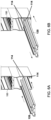
- FIGS. 12 A, 12 B and 12 C show a series of three cross-sectional end views of the troffer light fitting and FIG. 12 D is a cross-sectional end view of the troffer fitting arrangement for a white light output;
- FIG. 13 is a cross-sectional end view of a third embodiment of light fitting which is a wide troffer fitting
- Fitting 13 A, 13 B and 13 C show a series of three cross-sectional end views of the wide troffer fitting showing the sequence of how the gear tray is removed from the light fitting;
- FIG. 14 A is a cross-sectional end view of a fourth embodiment of a one-piece main body of a light fitting which is a narrow troffer fitting arranged to provide an amber output;
- FIG. 14 B is a similar view to FIG. 14 A but is arranged to provide a white light output.
- the first embodiment of light fitting 100 is a multi-functional (MF) light fitting which can be assembled or modified to produce down lighting or up lighting separately or together in a white or amber light output.
- MF multi-functional
- the light fitting 100 combines an elongate extruded main body 102 , two end pieces 103 and 104 . As shown in FIG. 1 , the end piece 104 includes an ethernet connection 105 . Other electrical connections can also be used but these are not shown in the drawings.
- a cover plate 106 is placed on the upper portion of the main body to block off the up-lighting section when not required.
- the main body extrusion 102 is provided with two separate sections a lower section 110 and an upper section 112 .
- the lower section 110 is used to contain the elements to provide down lighting and the upper section 112 is used to contain the elements to provide up lighting.
- These elements comprise an elongated gear tray 120 which supports the lighting element 130 such as LED's or the like. As shown in FIGS. 2 A and 2 B , channels 122 of the elongate gear tray 120 are engaged with internal ledges 114 of the lower section 110 to provide for down lighting and as shown in FIGS. 3 A and 3 B the channels of the elongated gear tray 120 are engaged with the internal ledges 116 of the upper section 112 to provide for up lighting.
- a clear prismatic lens 116 is provided on the lower section 110 or the upper section 112 as required.
- a diffuser 118 is also attached to the gear tray 120 where it is desired to have a light output which is not white but coloured with an amber light.
- gear trays 120 are located in the main body extrusion, one in the lower section 110 and one in the upper section 112 .
- Each gear tray 120 is provided with lighting element 130 and a diffuser lens 118 .
- a diffuser lens 116 is also provided in each of the sections 110 and 112 .
- the second embodiment 200 of light fitting according to the invention is shown in FIGS. 8 to 12 D .
- It is a troffer fitting which is a fitting which is installed on the support grid of a ceiling from above and the lower surface of the fitting is flush with the ceiling.
- the dimensions of the fitting 200 are 1182 mm in length, 170 mm in width and 60 mm in height. These dimensions can of course be varied depending on circumstances.
- the troffer fitting 200 comprises an elongate main body 202 which comprises an elongate extrusion 203 and two end caps 204 a removable gear tray cover 220 and filler plate 230 . Attached to the support legs 222 are a pair of retaining lugs 124 of the elongate gear tray 120 which is also used with the first embodiment 100 .
- the elongate gear tray 120 supports the lighting elements 130 as well as the diffuser 118 where required.
- a clear prismatic lens 116 is provided at the lower face 215 of the main body 202 .
- All the electrical and electronic circuitry necessary to operate the light fitting 200 are located and housed on the gear train 220 which is removable from the upper face 222 by simply undoing six screws 224 . With the screws 224 removed, the removable gear tray 222 is lifted vertically upwards as shown in FIG. 12 B and then tilted to one side to be removed from the light fitting 200 .
- the fitting 200 is suspended on its lower surface 202 by a ceiling support grid (not shown) above a clean room or other installation. This means that a technician repairing the light fitting can access the light fitting from above without entering the clean room or other installation. Also because of the way the light fitting 200 is designed, there is no danger of any component from the light fitting falling down into the clean room or other installation and possibly injuring a person beneath the light fitting or comprising the spatial integrity of the room or installation.
- FIGS. 13 , 13 A, 13 B, 13 C, 13 D and 13 E show the third embodiment of the invention according to the invention namely a wide troffer fitting 300 .
- the dimensions of the fitting 300 are 1182 mm in length, 268 mm in width and 60 mm in height. These dimensions can of course be varied depending on circumstances.
- the fitting 300 and fitting 200 include the same component parts which are given the like numerals.
- the fourth embodiment 400 is shown in FIGS. 14 A and 14 B is similar to the embodiments 200 and 300 but the extrusion 402 is of a narrower width. All other components are similar and given the same numerals.
Landscapes
- Engineering & Computer Science (AREA)
- General Engineering & Computer Science (AREA)
- Physics & Mathematics (AREA)
- Spectroscopy & Molecular Physics (AREA)
- Non-Portable Lighting Devices Or Systems Thereof (AREA)
Abstract
Description
-
- a second elongate extrusion operable for use as an elongate gear tray;
- the second elongate extrusion being engageable within the interior space of the main body extrusion to provide an optical chamber;
- the second elongate extrusion or gear tray of the optical chamber including electric lighting elements to support and provide the desired lighting output for the fitting.
-
- Both up-light and down-light functions integrated in one product;
- Fitted with collimated optics having a range of distributions;
- Fitted with amber or spectrum specific lenses to provide desired wavelengths of light;
- Having flexible layouts or designs thereby being able to transition from standard white light to spectrum controlled light, without alterations to the fitting or fixture but simply by relocating the extruded optical chamber;
- Having the ability to be controlled by sensors thereby setting the fittings or fixtures to site specific requirements;
- Having the flexibility to be operated with both mains power supply or power over ethernet;
- Having the ability to be connected and disconnected quickly and instantly;
- Having the capability for walk on ceiling applications;
- Flexibility to be used as an emergency lighting fixture in the event of a power failure; and
- Having a slim and narrow design to ensure optimum air flow return in controlled environments.
Claims (13)
Applications Claiming Priority (5)
| Application Number | Priority Date | Filing Date | Title |
|---|---|---|---|
| IES20210055 | 2021-03-15 | ||
| IES2021/0055 | 2021-03-15 | ||
| IES2021/0176 | 2021-10-08 | ||
| IES20210176 | 2021-10-08 | ||
| PCT/EP2022/056615 WO2022194818A1 (en) | 2021-03-15 | 2022-03-15 | Multifunctional light fitting with modified optical chamber |
Publications (2)
| Publication Number | Publication Date |
|---|---|
| US20240230064A1 US20240230064A1 (en) | 2024-07-11 |
| US12173867B2 true US12173867B2 (en) | 2024-12-24 |
Family
ID=81308496
Family Applications (1)
| Application Number | Title | Priority Date | Filing Date |
|---|---|---|---|
| US18/550,451 Active US12173867B2 (en) | 2021-03-15 | 2022-03-15 | Multifunctional light fitting with modified optical chamber |
Country Status (4)
| Country | Link |
|---|---|
| US (1) | US12173867B2 (en) |
| EP (1) | EP4308851A1 (en) |
| IL (1) | IL305980A (en) |
| WO (1) | WO2022194818A1 (en) |
Citations (5)
| Publication number | Priority date | Publication date | Assignee | Title |
|---|---|---|---|---|
| US20060146531A1 (en) | 2004-12-30 | 2006-07-06 | Ann Reo | Linear lighting apparatus with improved heat dissipation |
| US20150124440A1 (en) | 2013-11-04 | 2015-05-07 | Luminator Holding, Lp | Lighting housing with led illumination insert |
| US20180224103A1 (en) * | 2017-02-09 | 2018-08-09 | Walthill Opportunities L.L.C. | Strut light system with integrated light source |
| US20190041048A1 (en) * | 2015-12-18 | 2019-02-07 | Applied Electronic Materials, LLC | Modular lighting system including light modules with integrated led units |
| US20210071835A1 (en) * | 2016-04-20 | 2021-03-11 | Hubbell Incorporated | Multi-Function Lighting Fixture |
-
2022
- 2022-03-15 US US18/550,451 patent/US12173867B2/en active Active
- 2022-03-15 IL IL305980A patent/IL305980A/en unknown
- 2022-03-15 EP EP22716335.9A patent/EP4308851A1/en active Pending
- 2022-03-15 WO PCT/EP2022/056615 patent/WO2022194818A1/en not_active Ceased
Patent Citations (5)
| Publication number | Priority date | Publication date | Assignee | Title |
|---|---|---|---|---|
| US20060146531A1 (en) | 2004-12-30 | 2006-07-06 | Ann Reo | Linear lighting apparatus with improved heat dissipation |
| US20150124440A1 (en) | 2013-11-04 | 2015-05-07 | Luminator Holding, Lp | Lighting housing with led illumination insert |
| US20190041048A1 (en) * | 2015-12-18 | 2019-02-07 | Applied Electronic Materials, LLC | Modular lighting system including light modules with integrated led units |
| US20210071835A1 (en) * | 2016-04-20 | 2021-03-11 | Hubbell Incorporated | Multi-Function Lighting Fixture |
| US20180224103A1 (en) * | 2017-02-09 | 2018-08-09 | Walthill Opportunities L.L.C. | Strut light system with integrated light source |
Also Published As
| Publication number | Publication date |
|---|---|
| US20240230064A1 (en) | 2024-07-11 |
| EP4308851A1 (en) | 2024-01-24 |
| WO2022194818A1 (en) | 2022-09-22 |
| IL305980A (en) | 2023-11-01 |
Similar Documents
| Publication | Publication Date | Title |
|---|---|---|
| US11638339B2 (en) | Light fixtures and methods | |
| US11729877B2 (en) | Lighting fixture and methods | |
| US9052075B2 (en) | Standardized troffer fixture | |
| US9874333B2 (en) | Surface ambient wrap light fixture | |
| US7641361B2 (en) | Light emitting diode lamp | |
| US10379278B2 (en) | Outdoor and/or enclosed structure LED luminaire outdoor and/or enclosed structure LED luminaire having outward illumination | |
| US10502899B2 (en) | Outdoor and/or enclosed structure LED luminaire | |
| US7703946B2 (en) | LED wall wash light | |
| US20140355297A1 (en) | Optical components for luminaire | |
| US20130070455A1 (en) | Led lighting fixture | |
| KR20100017616A (en) | Light fixtures and lighting devices | |
| US20150167901A1 (en) | Linear shelf light fixture with gap filler elements | |
| US10247372B2 (en) | LED troffer lens assembly mount | |
| TWI633255B (en) | Lighting system and lighting method | |
| US10012354B2 (en) | Adjustable retrofit LED troffer | |
| US12173867B2 (en) | Multifunctional light fitting with modified optical chamber | |
| KR101762171B1 (en) | LED light source for luminaire | |
| JP2017062932A (en) | Recessed lighting fixture | |
| US10208923B2 (en) | Optical components for luminaire | |
| KR20130032416A (en) | Edge Down Light | |
| KR20120059041A (en) | a frame for light-instrument with radiation of heat and LED lighting using frame | |
| JP2008305785A (en) | lighting equipment | |
| RU2855766C1 (en) | Light-emitting panel | |
| JP2020161247A (en) | Lighting device | |
| KR101782220B1 (en) | LED Lighting |
Legal Events
| Date | Code | Title | Description |
|---|---|---|---|
| AS | Assignment |
Owner name: PATINA LIGHTING LIMITED, IRELAND Free format text: ASSIGNMENT OF ASSIGNORS INTEREST;ASSIGNOR:HAMILTON, GERARD;REEL/FRAME:064897/0217 Effective date: 20230913 |
|
| FEPP | Fee payment procedure |
Free format text: ENTITY STATUS SET TO UNDISCOUNTED (ORIGINAL EVENT CODE: BIG.); ENTITY STATUS OF PATENT OWNER: SMALL ENTITY |
|
| FEPP | Fee payment procedure |
Free format text: ENTITY STATUS SET TO SMALL (ORIGINAL EVENT CODE: SMAL); ENTITY STATUS OF PATENT OWNER: SMALL ENTITY |
|
| STPP | Information on status: patent application and granting procedure in general |
Free format text: NON FINAL ACTION MAILED |
|
| STPP | Information on status: patent application and granting procedure in general |
Free format text: NOTICE OF ALLOWANCE MAILED -- APPLICATION RECEIVED IN OFFICE OF PUBLICATIONS |
|
| STPP | Information on status: patent application and granting procedure in general |
Free format text: PUBLICATIONS -- ISSUE FEE PAYMENT VERIFIED |
|
| STCF | Information on status: patent grant |
Free format text: PATENTED CASE |