US12171625B2 - Method for animating models of the mandibular and maxillary arches of a patient in a corrected intermaxillary relationship - Google Patents
Method for animating models of the mandibular and maxillary arches of a patient in a corrected intermaxillary relationship Download PDFInfo
- Publication number
- US12171625B2 US12171625B2 US17/293,180 US201917293180A US12171625B2 US 12171625 B2 US12171625 B2 US 12171625B2 US 201917293180 A US201917293180 A US 201917293180A US 12171625 B2 US12171625 B2 US 12171625B2
- Authority
- US
- United States
- Prior art keywords
- patient
- mandibular
- mandible
- maxilla
- target position
- Prior art date
- Legal status (The legal status is an assumption and is not a legal conclusion. Google has not performed a legal analysis and makes no representation as to the accuracy of the status listed.)
- Active, expires
Links
Images


Classifications
-
- A—HUMAN NECESSITIES
- A61—MEDICAL OR VETERINARY SCIENCE; HYGIENE
- A61C—DENTISTRY; APPARATUS OR METHODS FOR ORAL OR DENTAL HYGIENE
- A61C11/00—Dental articulators, i.e. for simulating movement of the temporo-mandibular joints; Articulation forms or mouldings
- A61C11/006—Dental articulators, i.e. for simulating movement of the temporo-mandibular joints; Articulation forms or mouldings with an occlusal plate
-
- A—HUMAN NECESSITIES
- A61—MEDICAL OR VETERINARY SCIENCE; HYGIENE
- A61C—DENTISTRY; APPARATUS OR METHODS FOR ORAL OR DENTAL HYGIENE
- A61C11/00—Dental articulators, i.e. for simulating movement of the temporo-mandibular joints; Articulation forms or mouldings
- A61C11/02—Dental articulators, i.e. for simulating movement of the temporo-mandibular joints; Articulation forms or mouldings characterised by the arrangement, location or type of the hinge means ; Articulators with pivots
-
- A—HUMAN NECESSITIES
- A61—MEDICAL OR VETERINARY SCIENCE; HYGIENE
- A61C—DENTISTRY; APPARATUS OR METHODS FOR ORAL OR DENTAL HYGIENE
- A61C11/00—Dental articulators, i.e. for simulating movement of the temporo-mandibular joints; Articulation forms or mouldings
- A61C11/06—Dental articulators, i.e. for simulating movement of the temporo-mandibular joints; Articulation forms or mouldings with incisal guide
-
- A—HUMAN NECESSITIES
- A61—MEDICAL OR VETERINARY SCIENCE; HYGIENE
- A61C—DENTISTRY; APPARATUS OR METHODS FOR ORAL OR DENTAL HYGIENE
- A61C13/00—Dental prostheses; Making same
- A61C13/0003—Making bridge-work, inlays, implants or the like
- A61C13/0004—Computer-assisted sizing or machining of dental prostheses
-
- A—HUMAN NECESSITIES
- A61—MEDICAL OR VETERINARY SCIENCE; HYGIENE
- A61C—DENTISTRY; APPARATUS OR METHODS FOR ORAL OR DENTAL HYGIENE
- A61C7/00—Orthodontics, i.e. obtaining or maintaining the desired position of teeth, e.g. by straightening, evening, regulating, separating, or by correcting malocclusions
- A61C7/002—Orthodontic computer assisted systems
-
- G—PHYSICS
- G06—COMPUTING OR CALCULATING; COUNTING
- G06T—IMAGE DATA PROCESSING OR GENERATION, IN GENERAL
- G06T7/00—Image analysis
- G06T7/70—Determining position or orientation of objects or cameras
- G06T7/73—Determining position or orientation of objects or cameras using feature-based methods
-
- G—PHYSICS
- G16—INFORMATION AND COMMUNICATION TECHNOLOGY [ICT] SPECIALLY ADAPTED FOR SPECIFIC APPLICATION FIELDS
- G16H—HEALTHCARE INFORMATICS, i.e. INFORMATION AND COMMUNICATION TECHNOLOGY [ICT] SPECIALLY ADAPTED FOR THE HANDLING OR PROCESSING OF MEDICAL OR HEALTHCARE DATA
- G16H50/00—ICT specially adapted for medical diagnosis, medical simulation or medical data mining; ICT specially adapted for detecting, monitoring or modelling epidemics or pandemics
- G16H50/50—ICT specially adapted for medical diagnosis, medical simulation or medical data mining; ICT specially adapted for detecting, monitoring or modelling epidemics or pandemics for simulation or modelling of medical disorders
-
- A—HUMAN NECESSITIES
- A61—MEDICAL OR VETERINARY SCIENCE; HYGIENE
- A61C—DENTISTRY; APPARATUS OR METHODS FOR ORAL OR DENTAL HYGIENE
- A61C7/00—Orthodontics, i.e. obtaining or maintaining the desired position of teeth, e.g. by straightening, evening, regulating, separating, or by correcting malocclusions
- A61C7/36—Devices acting between upper and lower teeth
-
- G—PHYSICS
- G06—COMPUTING OR CALCULATING; COUNTING
- G06T—IMAGE DATA PROCESSING OR GENERATION, IN GENERAL
- G06T2207/00—Indexing scheme for image analysis or image enhancement
- G06T2207/30—Subject of image; Context of image processing
- G06T2207/30004—Biomedical image processing
- G06T2207/30036—Dental; Teeth
Definitions
- the present invention lies in the field of dentistry. More precisely, it relates to a method for animating models of the mandibular and maxillary arches of a patient in a corrected intermaxillary relationship.
- VDO vertical dimension of occlusion
- the vertical dimension of occlusion is generally defined as the height of the lower part of the face, or, more simply, the distance between the subnasale and the gnathion, during the occlusion phase.
- the subnasale is defined as the anterior nasal spine, while the gnathion is the most anterior point of the most sloping part of the chin protuberance.
- Increasing the vertical dimension of occlusion requires changing the position of the mandible relative to the maxilla (also known as the intermaxillary relationship (IMR)), which yields a change in the zone where the dental arches meet.
- IMR intermaxillary relationship
- the mandible can be moved only in a vertical direction and possibly in an antero-posterior direction.
- the practitioner has to simulate motions applied to the dental arches, using a mechanical or virtual articulator using three-dimensional physical or digital models of the mandibular arch and maxillary arch.
- the choice of the new mandibular position is performed by recording in the mouth on a wax sheet or by injecting a chemically setting material.
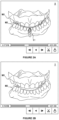
- the change can be made directly on the articulator, by moving the incisal rod T so that the model of the mandibular arch MD is spaced from the model of the maxillary arch MX by a distance equal to the desired increase in the vertical dimension of occlusion (see FIGS. 1 A and 1 B ).
- a facebow be used in order to locate the models relative to the axis of rotation of the mandible so that the arch spacing is as close to reality as possible.
- One aim of the invention is to overcome drawbacks of known techniques and to provide a method for animating models of the mandibular and maxillary arches of a patient in a corrected intermaxillary relationship.
- the invention provides a method for animating models of the mandibular and maxillary arches of a patient in a corrected intermaxillary relationship, comprising:
- the mandibular kinematics data is attached to this reference position.
- the present invention allows said data to be transposed to another so-called target position.
- the reference position is the patient's reference occlusal position before correcting the intermaxillary relationship.
- the record of the patient's mandibular kinematics describes the trajectory of markers integral with the mandible
- the rigid transformation is a transformation for switching from the position of the markers in the reference position to the position of the markers in the target position.
- the target position may be chosen by the user from the set of relative positions of the mandible relative to the maxilla in the record of the mandibular kinematics.
- the method comprises automatically preselecting a set of relative positions of the mandible relative to the maxilla, said set of positions being chosen such that each position of said set defines a vertical dimension of occlusion within a determined range.
- said preselection may be made from previously provided clinical criteria.
- the target position is not part of the set of positions present in the record of the mandibular kinematics, but may be simulated.
- the method advantageously comprises determining an axis of rotation of the mandible and creating virtual positions of the mandible along the path of rotation towards increasing or decreasing the vertical dimension of occlusion, the target position being chosen from said virtual positions.
- the target position is chosen such that the vertical dimension of occlusion (VDO) is increased by a value less than a threshold chosen so as not to cause a displacement of the axis of rotation of the mandibular condyles relative to the patient's temporal fossa.
- VDO vertical dimension of occlusion
- the target position is chosen such that the vertical dimension of occlusion defined at the incisor crown end is increased by less than 20 mm relative to the vertical dimension of occlusion defined by the patient's reference occlusal position.
- the target position is chosen so that the vertical dimension of occlusion (VDO) is decreased.
- the reference occlusal position of the mandible relative to the maxilla in the corrected intermaxillary relationship becomes the target position.
- FIG. 1 A illustrates a physiological articulator before increasing the vertical dimension of occlusion
- FIG. 1 B illustrates the physiological articulator of FIG. 1 A after increasing the vertical dimension of occlusion
- FIG. 2 A illustrates the record of the patient's mandibular kinematics before correcting the intermaxillary relationship
- FIG. 2 B illustrates the choice of the frame defining the target position of the mandible in the corrected intermaxillary relationship
- FIG. 2 C illustrates the application of the record of the patient's mandibular kinematics after correcting the intermaxillary relationship
- FIG. 3 schematically sets forth movements of the mandible as a function of the opening caused by the increase in the vertical dimension of occlusion
- FIG. 4 illustrates different mastication patterns recorded at the incisor crown end for functional and dysfunctional cycles.
- the system for implementing the method comprises:
- the dental arches Prior to the implementation of the method, the dental arches were scanned in a known and reproducible meshing relationship.
- a tool that can be used for this purpose is an intraoral optical impression camera. Such a camera is used to scan one arch and then the other, as well as a vestibular (sideways) impression of the meshing teeth to know the position of one arch relative to the other. This operation is known per se and is not as such part of the invention.
- Another method can consist in using a tabletop scanner. This scans plaster models from physicochemical impressions one after the other and then in the meshing position.
- the invention can indeed be implemented with any three-dimensional digital model of dental arches generated by commercially available digitizing techniques.
- the result of these digitizing operations is a surface grid of the maxillary arch and mandibular arch. Each grid is defined in an orthonormal reference frame of the digitizing device.
- the purpose of recording the mandibular kinematics is to provide information on how the mandible moves in space, and to use this kinematics to animate the three-dimensional models of the dental arches with a view to guiding the design of a dental prosthesis or other corrective device (orthodontic appliance, splint, . . . )
- recording the mandibular kinematics is implemented by equipping the patient with at least one marker integral with the patient's forehead (or any other location on the face integral with the maxilla) and at least one marker integral with the mandibular arch (by attachment to the mandible via a support or by direct attachment to the teeth), and by locating and recording the movements of said markers by means of a camera during mandibular motions of the patient.
- the markers can be diodes, black and white or coloured test patterns, or spheres, lands or other reflective objects.
- the movement of the markers in the mandible is tracked by the camera relative to the markers in the forehead.
- a rigid transformation enables the motion of the model of the mandibular arch relative to the model of the maxillary arch to be derived.
- the invention is not limited to any particular technique for acquiring mandibular kinematics.
- the movement of the mandible relative to the maxilla can be recorded by means of accelerometers or inertial units integral with the jaws.
- the record of the mandibular kinematics comprises a plurality of successive positions of the mandible relative to the maxilla during motions performed by the patient (for example mastication).
- the record is in the form of a digital file comprising a plurality of frames each corresponding to a relative position of the mandible and the maxilla.
- this digital file comprises a frame corresponding to a reference position of the patient (for example, but not limited to, the reference occlusal position). It is to this reference position that the mandibular kinematics data is attached.
- this digital file can further comprise a frame corresponding to a target position intended to become the patient's new reference position after implementing the correction.
- the practitioner can simulate the target position.
- an algorithm can determine the joint axis of the mandible relative to the maxilla. This axis typically passes through the condyles. The practitioner can then simulate a rotation of the digital model of the mandibular arch about this axis to determine a preferred position of the mandible relative to the maxilla. This preferred position is chosen as the target position.
- One or more frames can be created to represent virtual positions of the mandible along the path of rotation towards opening or decreasing the vertical dimension of occlusion.
- these additional frames are created by applying a rigid rotation-only transformation about the previously determined axis of rotation of the condyles, to the three-dimensional models of the frames recorded. These additional frames are added to the frames of the actually recorded mandibular kinematics.
- the target position can then be a second frame chosen by the practitioner from the additional frame(s).
- FIGS. 2 A to 2 C illustrate the record of the patient's mandibular kinematics before ( FIG. 2 A ) and after ( FIG. 2 C ) correcting the intermaxillary relationship respectively.
- the user can display this record on the screen and play it as many times as necessary.
- he/she has a user interface provided with a display zone to view the motions of the mandibular arch MD and maxillary arch MX and buttons for switching from one frame to the other and for exporting a particular frame.
- the user selects a first frame X that corresponds to the patient's reference position.
- the reference position is conventionally that of the first frame of the record of the mandibular kinematics.
- the patient is supposed to start the recording with the teeth clenched, which corresponds to the meshing position of the digital models of the arches, so-called a reference occlusal position.
- the practitioner can be required to place an interocclusal device (for example a splint) upon recording the mandibular kinematics to guide mandibular motions and find a particular position of the mandible relative to the maxilla, other than the initial meshing position.
- an interocclusal device for example a splint
- FIG. 2 A illustrates, for example, the mandibular arch MD in said reference position.
- the mandibular kinematics is represented as curve C 1 which illustrates the patient's mastication pattern at the incisor crown end.
- the user additionally selects a second frame Y which corresponds to the target position intended to become the patient's new reference position (see FIG. 2 B ).
- This target position is associated with a corrected intermaxillary relationship, for example corresponding to a vertical dimension of occlusion increased or decreased relative to the patient's initial vertical dimension of occlusion.
- the user can select the second frame Y from all the frames making up the record. This is done using the user's technical expertise to determine the amplitude of increase or decrease in the vertical dimension of occlusion adapted for the patient. This selection is made on the opening-closing path by choosing a repeatable motion. This motion can be generated by the patient himself/herself or guided by the practitioner who manipulates the patient's mandible to feel the terminal axial motion and verify that the return to occlusion is always at the same inter-arch meeting point.
- an algorithm for processing the record of the mandibular kinematics can preselect a set of frames, so as to limit the user's choice to a limited number of frames each corresponding to a vertical dimension of occlusion within a determined range.
- “Artificial intelligence” type algorithms can be used for this purpose. This preselection is advantageously based on clinical criteria previously input into the algorithm.
- the article by Jean-Pierre Lasserre [1] can be referred to, which provides rules to be observed when increasing the vertical dimension of occlusion.
- One of these rules is called the “1 ⁇ 3 rule”; it takes account of the fact that, on a physiological articulator, for the same increase in VDO of the lower face, the opening between the incisal rod and the incisal table is three times the opening between the second molars, and the opening between the central incisors is twice that between the second molars.
- the software can provide, when the practitioner seeks to determine a new mandibular position, a situation of the mandible such that the first molars are spaced 3 mm apart, which is the minimum space for making resistant prostheses. On the rotation path, the software thereby stops the mandible once this space is reached.
- cephalometric tracings on a profile radiograph can be used to determine the target position of the mandible in a sagittal plane by virtue of the calculation of certain angles.
- the profile radiograph imported into the software is superimposed on the 3D models. The results of the cephalometric analysis suggest a position of the mandible in the path of the prerecorded motions.
- the deglutition motion allows, in certain clinical situations, the vertical dimension of occlusion to be chosen, especially for an edentulous patient. Indeed, the mandible pauses on a highest position, which is a position that the software can suggest to the practitioner.
- the target position may not be chosen as a frame of the record of the mandibular kinematics, but can be simulated.
- the increase in the vertical dimension of occlusion below some threshold.
- the mandibular motion is guided by the patient's teeth, temporomandibular joint and neuromuscular activity.
- the axis of rotation of the condyles remains in the temporal fossa and the muscles of the joint remain in their resilient range; in this case, only changes in the dentition are likely to alter mandibular motion.
- the target position is preferably chosen so that the vertical dimension of occlusion defined at the incisor crown end is increased by less than 20 mm relative to the vertical dimension of occlusion defined by the patient's initial reference occlusal position, so as not to move the axis of rotation of the condyles.
- the practitioner may rather be confronted with the need to decrease the patient's vertical dimension of occlusion. This is the case, for example, when correcting prematurity, that is, contacts which, for pathological reasons, occur prematurely during rotation of the mandible.
- a prematurity can, for example, be caused by a tooth that is too prominent relative to the arch to which it belongs.
- the mandibular kinematics can be correct.
- the target position can be determined by simulating an abrasion of the prominent tooth and simulating the resulting jaw closure.
- Another example relates to a case where the patient is equipped with a splint that prevents or at least reduces erratic motions of the mandible as part of a neuromuscular reconditioning treatment; such a splint creates an extra thickness in the arch that it covers and is likely to increase the vertical distance of occlusion relative to the post-treatment situation where the patient is not wearing the splint.
- the mandibular kinematics generated by wearing the splint is of interest to the practitioner.
- the dental arches are scanned with the splint in place on the mandible or maxilla, and in the occlusal position on the splint.
- the reference position (marked by the first X-frame) corresponds to this situation.
- the target position can exist in the record of the mandibular kinematics or can be simulated.
- the target position can exist if the record of the mandibular kinematics starts with the splint in place and then the practitioner removes the splint from the patient's mouth upon recording, and the patient moves to or is guided to the target position, shown as a second frame Y.
- the target position can be simulated by being chosen along the simulated path of the mandible during rotation about its axis.
- the two models of dental arches are seen moving with a space between them.
- the target position is chosen as a frame from the recording or simulated. If the target position is chosen, it can be the first frame of the recording or another position corresponding to another frame of the part of the record in which the splint is not in place.
- the simulation of the target position has been described above.
- an algorithm calculates a rigid transformation from the frame X to the frame Y.
- the rigid transformation is the transformation for switching from the position of the markers in frame X to the position of said markers in frame Y. For example, if the position of MD relative to MX in frame X (respectively frame Y) is represented by the matrix Tx (respectively Ty), then the rigid transformation of MD from frame X to frame Y is represented by the matrix (Ty) ⁇ 1 *Tx.
- an algorithm applies the previously calculated rigid transformation (curve C 2 ) to the recorded mandibular kinematics.
- the models of the mandibular and maxillary arches are then animated with the kinematics C 2 .
- an algorithm applies the rigid transformation to the model of the mandibular arch and animates the models of arches that have undergone said rigid transformation with the patient's initially recorded mandibular kinematics.
- the practitioner checks whether the patient's mandibular kinematics is functional or dysfunctional before implementing the rest of the method and especially before transposing this kinematics to the corrected intermaxillary relationship.
- he/she can trace a mastication pattern and compare this pattern with types of patterns identified as functional or dysfunctional.
- FIG. 4 illustrates, on the left hand side, theoretical mastication patterns at the incisor crown end for functional cycles (the top three cycles) and dysfunctional cycles (the bottom four cycles).
- the right-hand side of FIG. 4 illustrates a clinical pattern, which is considered as functional.
- the person skilled in the art could trace a mastication pattern recorded at a point other than the incisor crown end, for example the condyles.
- the method described above is only implemented if the patient's mandibular kinematics is functional. In the case where the patient's mandibular kinematics is dysfunctional, the practitioner will turn to other tools, such as an articulator.
- the method just described can find application in orthodontics, placement of dental prostheses or maxillofacial surgery.
- a patient's teeth can be abraded by mechanical stress (bruxism) or by chemical erosion due to the consumption of acidic foods or drinks.
- the teeth can be natural or prosthetic. This tooth destruction occurs slowly and the masticatory function has time to sculpt the teeth by keeping the essential guides on the occlusal tables, despite their destruction and loss of vertical dimension.
- a complementary examination of the health of the manducatory apparatus is established prior to the implementation of the present invention. If the result is positive, the practitioner will be willing to preserve the way the mandible moves, but will have to restore the vertical dimension of occlusion.
- the invention aims at transposing the same mandibular kinematics, comfortable for the patient, to a new position of the mandibular arch.
- the new space created will be filled with new prosthetic devices the shape and position of which will not disturb the mandibular motility.
- the clinical approach is substantially the same as that described above. Instead of filling the space with prostheses, the teeth will be moved and brought into meshing. In this case, the occlusion will also be carried out in accordance with the patient's true motions.
Landscapes
- Health & Medical Sciences (AREA)
- Public Health (AREA)
- General Health & Medical Sciences (AREA)
- Epidemiology (AREA)
- Engineering & Computer Science (AREA)
- Animal Behavior & Ethology (AREA)
- Veterinary Medicine (AREA)
- Dentistry (AREA)
- Life Sciences & Earth Sciences (AREA)
- Oral & Maxillofacial Surgery (AREA)
- Medical Informatics (AREA)
- General Engineering & Computer Science (AREA)
- Biomedical Technology (AREA)
- Data Mining & Analysis (AREA)
- Databases & Information Systems (AREA)
- Pathology (AREA)
- Primary Health Care (AREA)
- Computer Vision & Pattern Recognition (AREA)
- Physics & Mathematics (AREA)
- General Physics & Mathematics (AREA)
- Theoretical Computer Science (AREA)
- Dental Tools And Instruments Or Auxiliary Dental Instruments (AREA)
- Orthopedics, Nursing, And Contraception (AREA)
Abstract
Description
-
- providing three-dimensional digital models of the patient's mandibular and maxillary arches,
- providing a record of the patient's mandibular kinematics, said record comprising a plurality of relative positions of the patient's mandible with respect to the maxilla,
- selecting, from said positions, a reference position of the mandible relative to the patient's maxilla,
- determining a target position of the mandible relative to the maxilla, said target position defining a corrected intermaxillary relationship of the patient,
- determining a rigid transformation between the reference position (X) and the target position,
- applying said rigid transformation to (i) the record of the patient's mandibular kinematics to animate the three-dimensional digital models of the mandibular and maxillary arches with the record resulting from the application of said rigid transformation, or (ii) the three-dimensional digital model of the mandible, the record of the mandibular kinematics provided being applied to the three-dimensional digital models of the mandible and maxilla resulting from the application of said rigid transformation to animate said models.
-
- a computer comprising a processor for receiving data previously obtained, especially digital models of the patient's mandibular and maxillary arches and a record of the patient's mandibular kinematics, and for running animation and modelling algorithms, and
- a screen for displaying the various steps implemented during the method, with a user interface allowing the practitioner to input treatment parameters and to view the mandibular kinematics before and after correction.
Obtaining Three-Dimensional Digital Models of the Mandibular and Maxillary Arches
- WO 2013/030511
- WO 2016/062962
- [1] Jean-Francois Lasserre, “Comprendre l'augmentation de DVO dans les approches minimales invasives des traitements de l'usure et des anomalies de l'émail”, Quintessence International
Claims (15)
Applications Claiming Priority (3)
| Application Number | Priority Date | Filing Date | Title |
|---|---|---|---|
| FR1871744 | 2018-11-23 | ||
| FR1871744A FR3088820B1 (en) | 2018-11-23 | 2018-11-23 | METHOD FOR ANIMATING MODELS OF THE MANDIBULAR AND MAXILLARY ARCHES OF A PATIENT IN A CORRECTED INTERMAXILLARY RELATION |
| PCT/FR2019/052798 WO2020104760A2 (en) | 2018-11-23 | 2019-11-25 | Method for animating models of the mandibular and maxillary arches of a patient in a corrected intermaxillary relationship |
Publications (2)
| Publication Number | Publication Date |
|---|---|
| US20220008174A1 US20220008174A1 (en) | 2022-01-13 |
| US12171625B2 true US12171625B2 (en) | 2024-12-24 |
Family
ID=66867195
Family Applications (1)
| Application Number | Title | Priority Date | Filing Date |
|---|---|---|---|
| US17/293,180 Active 2041-02-23 US12171625B2 (en) | 2018-11-23 | 2019-11-25 | Method for animating models of the mandibular and maxillary arches of a patient in a corrected intermaxillary relationship |
Country Status (8)
| Country | Link |
|---|---|
| US (1) | US12171625B2 (en) |
| EP (2) | EP4238533A3 (en) |
| JP (1) | JP2022509164A (en) |
| CN (1) | CN113347943A (en) |
| DK (1) | DK3883493T3 (en) |
| ES (1) | ES2962213T3 (en) |
| FR (1) | FR3088820B1 (en) |
| WO (1) | WO2020104760A2 (en) |
Families Citing this family (7)
| Publication number | Priority date | Publication date | Assignee | Title |
|---|---|---|---|---|
| CA3131694A1 (en) | 2019-03-26 | 2020-10-01 | Kjeld A. AAMODT | Methods and systems for orthodontic treatment planning |
| RU2735984C2 (en) * | 2020-06-10 | 2020-11-11 | Арсен Овсепович Казарян | Method for constructing and displaying computer 3d models of temporomandibular joints |
| US20220218438A1 (en) * | 2021-01-14 | 2022-07-14 | Orthosnap Corp. | Creating three-dimensional (3d) animation |
| US11213373B1 (en) | 2021-05-14 | 2022-01-04 | Oxilio Ltd | Methods and systems for modeling mandibular motion |
| EP4419041A4 (en) * | 2021-10-18 | 2025-08-27 | Cvstom Co | Methods and systems for planning orthodontic treatment using a virtual jaw articulator |
| CN114863056B (en) * | 2022-03-23 | 2022-11-22 | 北京大学口腔医学院 | Method and device for generating temporomandibular joint condylar motion envelope surface based on surface type parameters |
| IT202300009792A1 (en) * | 2023-05-16 | 2024-11-16 | Perrotti Mario | METHOD FOR RECORDING MANDIBULAR MOVEMENTS |
Citations (20)
| Publication number | Priority date | Publication date | Assignee | Title |
|---|---|---|---|---|
| US20020048741A1 (en) | 1997-09-22 | 2002-04-25 | 3M Innovative Properties Company | Methods for use in dental articulation |
| US20050107687A1 (en) | 2003-11-14 | 2005-05-19 | Anderson Peter T. | System and method for distortion reduction in an electromagnetic tracker |
| CN1833617A (en) | 2006-04-13 | 2006-09-20 | 上海交通大学 | Method for making computer-aided generation positioning board |
| US20090068617A1 (en) | 2006-03-03 | 2009-03-12 | Lauren Mark D | Method Of Designing Dental Devices Using Four-Dimensional Data |
| US20090082989A1 (en) | 2007-09-24 | 2009-03-26 | General Electric Company | System and method for improving the distortion tolerance of an electromagnetic tracking system |
| US20110004430A1 (en) | 2003-04-17 | 2011-01-06 | Northern Digital Inc. | Eddy current detection and compensation |
| US20110045428A1 (en) * | 2009-08-21 | 2011-02-24 | Anatoliy Boltunov | Digital dental modeling |
| US20110191081A1 (en) | 2008-04-29 | 2011-08-04 | Materialise Dental N.V. | Method to determine the impact of a proposed dental modification on the temporomandibular joint |
| WO2013030511A2 (en) | 2011-08-31 | 2013-03-07 | Jaisson Maxime | Method for designing a dental appliance |
| WO2016062962A1 (en) | 2014-10-20 | 2016-04-28 | Modjaw | Method and system for modeling the mandibular kinematics of a patient |
| US20160378883A1 (en) * | 2015-06-24 | 2016-12-29 | Kelly Lucas | Systems and methods for producing anterior guidance package (agp) equipped splint |
| US20170209072A1 (en) | 2016-01-26 | 2017-07-27 | St. Jude Medical International Holding S.À R.L. | Magnetic field distortion detection and correction in a magnetic localization system |
| US20180005377A1 (en) | 2016-06-29 | 2018-01-04 | 3M Innovative Properties Company | Virtual model of articulation from intra-oral scans |
| US20180049855A1 (en) * | 2014-07-22 | 2018-02-22 | Medicom Llc | Computer, Computer-Implemented Method, Computer Program, and Face-Bow |
| US20180336736A1 (en) * | 2015-02-23 | 2018-11-22 | Osstemimplant Co., Ltd. | Method for simulating mandibular movement, device for same and recording medium for recording same |
| US20190000592A1 (en) * | 2017-06-30 | 2019-01-03 | Align Technology, Inc. | Treatment of temperomandibular joint dysfunction with aligner therapy |
| US20190000559A1 (en) | 2017-06-28 | 2019-01-03 | Auris Health, Inc. | Electromagnetic field generator alignment |
| US20200060796A1 (en) * | 2017-01-13 | 2020-02-27 | Ignident Gmbh | Device and method for measuring a movement of a mandible |
| US20200268495A1 (en) * | 2017-09-20 | 2020-08-27 | Obschestvo S Ogranichennoi Otvetstvennostyu "Avantis3D" [Ru/Ru] | Method for using a dynamic virtual articulator for simulating occlusion when designing a dental prosthesis for a patient, and data carrier |
| US20200319267A1 (en) | 2019-04-02 | 2020-10-08 | Ascension Technology Corporation | Distortion correction for tracking an object in a magnetic field |
-
2018
- 2018-11-23 FR FR1871744A patent/FR3088820B1/en active Active
-
2019
- 2019-11-25 JP JP2021529101A patent/JP2022509164A/en active Pending
- 2019-11-25 DK DK19839344.9T patent/DK3883493T3/en active
- 2019-11-25 EP EP23187708.5A patent/EP4238533A3/en active Pending
- 2019-11-25 US US17/293,180 patent/US12171625B2/en active Active
- 2019-11-25 CN CN201980089211.8A patent/CN113347943A/en active Pending
- 2019-11-25 WO PCT/FR2019/052798 patent/WO2020104760A2/en not_active Ceased
- 2019-11-25 EP EP19839344.9A patent/EP3883493B1/en active Active
- 2019-11-25 ES ES19839344T patent/ES2962213T3/en active Active
Patent Citations (21)
| Publication number | Priority date | Publication date | Assignee | Title |
|---|---|---|---|---|
| US20020048741A1 (en) | 1997-09-22 | 2002-04-25 | 3M Innovative Properties Company | Methods for use in dental articulation |
| US20110004430A1 (en) | 2003-04-17 | 2011-01-06 | Northern Digital Inc. | Eddy current detection and compensation |
| US20050107687A1 (en) | 2003-11-14 | 2005-05-19 | Anderson Peter T. | System and method for distortion reduction in an electromagnetic tracker |
| US20090068617A1 (en) | 2006-03-03 | 2009-03-12 | Lauren Mark D | Method Of Designing Dental Devices Using Four-Dimensional Data |
| CN1833617A (en) | 2006-04-13 | 2006-09-20 | 上海交通大学 | Method for making computer-aided generation positioning board |
| US20090082989A1 (en) | 2007-09-24 | 2009-03-26 | General Electric Company | System and method for improving the distortion tolerance of an electromagnetic tracking system |
| US20110191081A1 (en) | 2008-04-29 | 2011-08-04 | Materialise Dental N.V. | Method to determine the impact of a proposed dental modification on the temporomandibular joint |
| US20110045428A1 (en) * | 2009-08-21 | 2011-02-24 | Anatoliy Boltunov | Digital dental modeling |
| WO2013030511A2 (en) | 2011-08-31 | 2013-03-07 | Jaisson Maxime | Method for designing a dental appliance |
| US20140294273A1 (en) * | 2011-08-31 | 2014-10-02 | Maxime Jaisson | Method for designing an orthodontic appliance |
| US20180049855A1 (en) * | 2014-07-22 | 2018-02-22 | Medicom Llc | Computer, Computer-Implemented Method, Computer Program, and Face-Bow |
| WO2016062962A1 (en) | 2014-10-20 | 2016-04-28 | Modjaw | Method and system for modeling the mandibular kinematics of a patient |
| US20180336736A1 (en) * | 2015-02-23 | 2018-11-22 | Osstemimplant Co., Ltd. | Method for simulating mandibular movement, device for same and recording medium for recording same |
| US20160378883A1 (en) * | 2015-06-24 | 2016-12-29 | Kelly Lucas | Systems and methods for producing anterior guidance package (agp) equipped splint |
| US20170209072A1 (en) | 2016-01-26 | 2017-07-27 | St. Jude Medical International Holding S.À R.L. | Magnetic field distortion detection and correction in a magnetic localization system |
| US20180005377A1 (en) | 2016-06-29 | 2018-01-04 | 3M Innovative Properties Company | Virtual model of articulation from intra-oral scans |
| US20200060796A1 (en) * | 2017-01-13 | 2020-02-27 | Ignident Gmbh | Device and method for measuring a movement of a mandible |
| US20190000559A1 (en) | 2017-06-28 | 2019-01-03 | Auris Health, Inc. | Electromagnetic field generator alignment |
| US20190000592A1 (en) * | 2017-06-30 | 2019-01-03 | Align Technology, Inc. | Treatment of temperomandibular joint dysfunction with aligner therapy |
| US20200268495A1 (en) * | 2017-09-20 | 2020-08-27 | Obschestvo S Ogranichennoi Otvetstvennostyu "Avantis3D" [Ru/Ru] | Method for using a dynamic virtual articulator for simulating occlusion when designing a dental prosthesis for a patient, and data carrier |
| US20200319267A1 (en) | 2019-04-02 | 2020-10-08 | Ascension Technology Corporation | Distortion correction for tracking an object in a magnetic field |
Non-Patent Citations (3)
| Title |
|---|
| International Search Report in co-pending related, PCT Application No. PCT/FR2019/052798, mailed Jun. 16, 2020. |
| Jean-Francois Lasserre « Comprendre l'augmentation de DVO dans les approches minimales invasives des traitements de l'usure et des anomalies de l'email » Quintessence International, OA News, May 2016. |
| Preliminary Search in co-pending related French Application No. FR 1871744, mailed Sep. 27, 2019. |
Also Published As
| Publication number | Publication date |
|---|---|
| DK3883493T3 (en) | 2023-10-30 |
| JP2022509164A (en) | 2022-01-20 |
| WO2020104760A3 (en) | 2020-08-06 |
| EP3883493B1 (en) | 2023-08-02 |
| WO2020104760A2 (en) | 2020-05-28 |
| US20220008174A1 (en) | 2022-01-13 |
| EP4238533A2 (en) | 2023-09-06 |
| FR3088820B1 (en) | 2022-08-12 |
| CN113347943A (en) | 2021-09-03 |
| FR3088820A1 (en) | 2020-05-29 |
| EP3883493A2 (en) | 2021-09-29 |
| EP4238533A3 (en) | 2023-11-01 |
| ES2962213T3 (en) | 2024-03-18 |
Similar Documents
| Publication | Publication Date | Title |
|---|---|---|
| US12171625B2 (en) | Method for animating models of the mandibular and maxillary arches of a patient in a corrected intermaxillary relationship | |
| US11751981B2 (en) | Dynamic virtual articulator for simulating occlusion of teeth | |
| US12544984B2 (en) | System and method for producing dental solutions incorporating a guidance package | |
| US11633265B2 (en) | Dynamic virtual articulator for simulating occlusion of teeth | |
| JP6775621B2 (en) | Methods and systems for obtaining data from people to create 3D models | |
| WO2012140021A2 (en) | Modeling and manufacturing orthodontic appliances | |
| EP3998985B1 (en) | Virtual articulation in orthodontic and dental treatment planning | |
| KR100419380B1 (en) | Method for forming orthodontic brace | |
| CN120769733A (en) | Method and analysis system for generating a digital 3D model of a patient's dentition | |
| HK40099905A (en) | Method for animating models of the mandibular and maxillary arches of a patient bearing a gutter in a corrected intermaxillary relationship | |
| HK40061303B (en) | Method for animating models of the mandibular and maxillary arches of a patient in a corrected intermaxillary relationship | |
| HK40061303A (en) | Method for animating models of the mandibular and maxillary arches of a patient in a corrected intermaxillary relationship |
Legal Events
| Date | Code | Title | Description |
|---|---|---|---|
| FEPP | Fee payment procedure |
Free format text: ENTITY STATUS SET TO UNDISCOUNTED (ORIGINAL EVENT CODE: BIG.); ENTITY STATUS OF PATENT OWNER: LARGE ENTITY |
|
| AS | Assignment |
Owner name: MODJAW, FRANCE Free format text: ASSIGNMENT OF ASSIGNORS INTEREST;ASSIGNOR:JAISSON, MAXIME;REEL/FRAME:057342/0288 Effective date: 20210830 |
|
| STPP | Information on status: patent application and granting procedure in general |
Free format text: DOCKETED NEW CASE - READY FOR EXAMINATION |
|
| STPP | Information on status: patent application and granting procedure in general |
Free format text: NON FINAL ACTION MAILED |
|
| STPP | Information on status: patent application and granting procedure in general |
Free format text: RESPONSE TO NON-FINAL OFFICE ACTION ENTERED AND FORWARDED TO EXAMINER |
|
| STPP | Information on status: patent application and granting procedure in general |
Free format text: FINAL REJECTION MAILED |
|
| STPP | Information on status: patent application and granting procedure in general |
Free format text: DOCKETED NEW CASE - READY FOR EXAMINATION |
|
| STPP | Information on status: patent application and granting procedure in general |
Free format text: NOTICE OF ALLOWANCE MAILED -- APPLICATION RECEIVED IN OFFICE OF PUBLICATIONS |
|
| STPP | Information on status: patent application and granting procedure in general |
Free format text: PUBLICATIONS -- ISSUE FEE PAYMENT VERIFIED |
|
| STCF | Information on status: patent grant |
Free format text: PATENTED CASE |