US12167685B2 - Organic compounds and organic light emitting display device using the same - Google Patents
Organic compounds and organic light emitting display device using the same Download PDFInfo
- Publication number
- US12167685B2 US12167685B2 US17/078,155 US202017078155A US12167685B2 US 12167685 B2 US12167685 B2 US 12167685B2 US 202017078155 A US202017078155 A US 202017078155A US 12167685 B2 US12167685 B2 US 12167685B2
- Authority
- US
- United States
- Prior art keywords
- substituted
- unsubstituted
- groups
- group
- light emitting
- Prior art date
- Legal status (The legal status is an assumption and is not a legal conclusion. Google has not performed a legal analysis and makes no representation as to the accuracy of the status listed.)
- Active, expires
Links
Images


Classifications
-
- C—CHEMISTRY; METALLURGY
- C07—ORGANIC CHEMISTRY
- C07D—HETEROCYCLIC COMPOUNDS
- C07D407/00—Heterocyclic compounds containing two or more hetero rings, at least one ring having oxygen atoms as the only ring hetero atoms, not provided for by group C07D405/00
- C07D407/02—Heterocyclic compounds containing two or more hetero rings, at least one ring having oxygen atoms as the only ring hetero atoms, not provided for by group C07D405/00 containing two hetero rings
- C07D407/12—Heterocyclic compounds containing two or more hetero rings, at least one ring having oxygen atoms as the only ring hetero atoms, not provided for by group C07D405/00 containing two hetero rings linked by a chain containing hetero atoms as chain links
-
- C—CHEMISTRY; METALLURGY
- C07—ORGANIC CHEMISTRY
- C07D—HETEROCYCLIC COMPOUNDS
- C07D311/00—Heterocyclic compounds containing six-membered rings having one oxygen atom as the only hetero atom, condensed with other rings
- C07D311/96—Heterocyclic compounds containing six-membered rings having one oxygen atom as the only hetero atom, condensed with other rings spiro-condensed with carbocyclic rings or ring systems
-
- C—CHEMISTRY; METALLURGY
- C09—DYES; PAINTS; POLISHES; NATURAL RESINS; ADHESIVES; COMPOSITIONS NOT OTHERWISE PROVIDED FOR; APPLICATIONS OF MATERIALS NOT OTHERWISE PROVIDED FOR
- C09K—MATERIALS FOR MISCELLANEOUS APPLICATIONS, NOT PROVIDED FOR ELSEWHERE
- C09K11/00—Luminescent materials, e.g. electroluminescent or chemiluminescent
- C09K11/06—Luminescent materials, e.g. electroluminescent or chemiluminescent containing organic luminescent materials
-
- H—ELECTRICITY
- H10—SEMICONDUCTOR DEVICES; ELECTRIC SOLID-STATE DEVICES NOT OTHERWISE PROVIDED FOR
- H10K—ORGANIC ELECTRIC SOLID-STATE DEVICES
- H10K85/00—Organic materials used in the body or electrodes of devices covered by this subclass
- H10K85/60—Organic compounds having low molecular weight
- H10K85/631—Amine compounds having at least two aryl rest on at least one amine-nitrogen atom, e.g. triphenylamine
- H10K85/633—Amine compounds having at least two aryl rest on at least one amine-nitrogen atom, e.g. triphenylamine comprising polycyclic condensed aromatic hydrocarbons as substituents on the nitrogen atom
-
- H—ELECTRICITY
- H10—SEMICONDUCTOR DEVICES; ELECTRIC SOLID-STATE DEVICES NOT OTHERWISE PROVIDED FOR
- H10K—ORGANIC ELECTRIC SOLID-STATE DEVICES
- H10K85/00—Organic materials used in the body or electrodes of devices covered by this subclass
- H10K85/60—Organic compounds having low molecular weight
- H10K85/631—Amine compounds having at least two aryl rest on at least one amine-nitrogen atom, e.g. triphenylamine
- H10K85/636—Amine compounds having at least two aryl rest on at least one amine-nitrogen atom, e.g. triphenylamine comprising heteroaromatic hydrocarbons as substituents on the nitrogen atom
-
- C—CHEMISTRY; METALLURGY
- C09—DYES; PAINTS; POLISHES; NATURAL RESINS; ADHESIVES; COMPOSITIONS NOT OTHERWISE PROVIDED FOR; APPLICATIONS OF MATERIALS NOT OTHERWISE PROVIDED FOR
- C09K—MATERIALS FOR MISCELLANEOUS APPLICATIONS, NOT PROVIDED FOR ELSEWHERE
- C09K2211/00—Chemical nature of organic luminescent or tenebrescent compounds
- C09K2211/10—Non-macromolecular compounds
- C09K2211/1018—Heterocyclic compounds
-
- H—ELECTRICITY
- H10—SEMICONDUCTOR DEVICES; ELECTRIC SOLID-STATE DEVICES NOT OTHERWISE PROVIDED FOR
- H10K—ORGANIC ELECTRIC SOLID-STATE DEVICES
- H10K50/00—Organic light-emitting devices
- H10K50/10—OLEDs or polymer light-emitting diodes [PLED]
- H10K50/14—Carrier transporting layers
- H10K50/15—Hole transporting layers
-
- H—ELECTRICITY
- H10—SEMICONDUCTOR DEVICES; ELECTRIC SOLID-STATE DEVICES NOT OTHERWISE PROVIDED FOR
- H10K—ORGANIC ELECTRIC SOLID-STATE DEVICES
- H10K50/00—Organic light-emitting devices
- H10K50/10—OLEDs or polymer light-emitting diodes [PLED]
- H10K50/18—Carrier blocking layers
-
- H—ELECTRICITY
- H10—SEMICONDUCTOR DEVICES; ELECTRIC SOLID-STATE DEVICES NOT OTHERWISE PROVIDED FOR
- H10K—ORGANIC ELECTRIC SOLID-STATE DEVICES
- H10K50/00—Organic light-emitting devices
- H10K50/10—OLEDs or polymer light-emitting diodes [PLED]
- H10K50/18—Carrier blocking layers
- H10K50/181—Electron blocking layers
-
- H—ELECTRICITY
- H10—SEMICONDUCTOR DEVICES; ELECTRIC SOLID-STATE DEVICES NOT OTHERWISE PROVIDED FOR
- H10K—ORGANIC ELECTRIC SOLID-STATE DEVICES
- H10K85/00—Organic materials used in the body or electrodes of devices covered by this subclass
- H10K85/60—Organic compounds having low molecular weight
- H10K85/615—Polycyclic condensed aromatic hydrocarbons, e.g. anthracene
- H10K85/626—Polycyclic condensed aromatic hydrocarbons, e.g. anthracene containing more than one polycyclic condensed aromatic rings, e.g. bis-anthracene
-
- H—ELECTRICITY
- H10—SEMICONDUCTOR DEVICES; ELECTRIC SOLID-STATE DEVICES NOT OTHERWISE PROVIDED FOR
- H10K—ORGANIC ELECTRIC SOLID-STATE DEVICES
- H10K85/00—Organic materials used in the body or electrodes of devices covered by this subclass
- H10K85/60—Organic compounds having low molecular weight
- H10K85/649—Aromatic compounds comprising a hetero atom
- H10K85/657—Polycyclic condensed heteroaromatic hydrocarbons
- H10K85/6574—Polycyclic condensed heteroaromatic hydrocarbons comprising only oxygen in the heteroaromatic polycondensed ring system, e.g. cumarine dyes
Definitions
- the present disclosure relates to organic compounds and an organic light emitting display device using the same. More particularly, the present disclosure relates to novel organic compounds with hole transport properties and electron blocking properties and an organic light emitting display device which can have high efficiency and long lifetime by applying the organic compounds to an organic layer.
- An organic light emitting display device uses an organic light emitting element that is a self-light emitting element.
- the organic light emitting display device does not need an additional light source unlike a liquid crystal display device (LCD) using a backlight unit. Therefore, the organic light emitting display device has a simple structure and is easy to manufacture. Further, the organic light emitting display device is advantageous in terms of power consumption since it is driven with a low voltage. Also, the organic light emitting display device has excellent color expression ability, high luminance, wide viewing angle, high response speed, and high contrast ratio. Therefore, the organic light emitting display device is being actively developed as a next-generation display device.
- organic light emitting element When a voltage is applied to an organic light emitting element, holes injected from an anode and electrons injected from a cathode recombine in a light emitting layer to form excitons.
- the organic light emitting element emits light when the excitons thus formed transit from an unstable excited state to a stable ground state.
- the organic light emitting element includes various layers to improve luminous efficiency in addition to an anode that supplies holes, a cathode that supplies electrons and a light emitting layer (EML).
- the organic light emitting element has a structure in which an anode, a hole injection layer (HIL), a hole transport layer (HTL), a light emitting layer, an electron transport layer (ETL) and an electron injection layer (EIL) are laminated.
- HIL hole injection layer
- HTL hole transport layer
- ETL electron transport layer
- EIL electron injection layer
- embodiments of the present disclosure are directed to organic compounds and an organic light emitting display device using the same that substantially obviate one or more of the problems due to limitations and disadvantages of the related art.
- a light emitting layer of an organic light emitting element needs to be designed so that holes and electrons can be smoothly transferred, and charges injected into the light emitting layer do not leak to an adjacent layer.
- An object to be achieved by the present disclosure is to provide organic compounds that have hole transport properties and electron blocking properties and thus can be used in a hole transport layer or an electron blocking layer of an organic light emitting display device.
- Another object to be achieved by the present disclosure is to provide an organic light emitting display device with high luminous efficiency and long lifetime.
- an organic compound is represented by the following Chemical Formula 1:
- an organic light emitting display device comprising:
- the recombination efficiency of holes and electrons in the light emitting layer can be improved, which results in high luminous efficiency and long lifetime of the organic light emitting display device.
- the present disclosure it is possible to provide a hole transport and electron blocking organic compound having a specific structure.
- the organic compound of the present disclosure is used in an organic layer, specifically a hole transport layer or an electron blocking layer, of an organic light emitting display device.
- an organic layer specifically a hole transport layer or an electron blocking layer
- FIG. 1 is a schematic cross-sectional view of an organic light emitting display device according to an exemplary embodiment of the present disclosure.
- FIG. 2 is an enlarged view provided to explain the organic light emitting display device according to an exemplary embodiment of the present disclosure.
- FIG. 3 is a cross-sectional view of a blue organic light emitting element of an organic light emitting display device according to another exemplary embodiment of the present disclosure.
- first”, “second”, and the like are used for describing various components, these components are not confined by these terms. These terms are merely used for distinguishing one component from the other components. Therefore, a first component to be mentioned below may be a second component in a technical concept of the present disclosure.
- a size and a thickness of each component illustrated in the drawing are illustrated for convenience of description, and the present disclosure is not limited to the size and the thickness of the component illustrated.
- unsubstituted means that a hydrogen atom is not substituted or the hydrogen atom is substituted by an isotope selected from protium, deuterium and tritium.
- substituted means that a hydrogen atom or atom group of a compound is substituted by a substituent.
- the substituent may be selected from C 1 -C 30 alkyl groups, C 2 -C 30 alkenyl groups, C 2 -C 24 alkynyl groups, C 3 -C 12 cycloalkyl groups, C 2 -C 30 heterocycloalkyl groups, C 7 -C 30 aralkyl groups, C 6 -C 30 aryl groups, C 5 -C 30 heteroaralkyl groups, C 1 -C 30 alkoxy groups, C 1 -C 30 alkylamino groups, C 6 -C 30 arylamino groups, C 7 -C 30 aralkylamino groups, C 2 -C 24 heteroarylamino groups, C 1 -C 30 alkylsilyl groups, C 6 -C 30 arylsilyl groups, C 6 -C 30 aryloxy groups, C 1 -C 30 alkylsilyl groups
- hetero means that at least one of carbon atoms constituting a cyclic saturated or unsaturated hydrocarbon is substituted by a heteroatom such as N, O, S and Se.
- alkyl refers to a monovalent substituent derived from linear or branched saturated hydrocarbons.
- the alkyl may include methyl, ethyl, propyl, n-butyl, iso-butyl, n-pentyl, hexyl, and the like, but may not be limited thereto.
- alkenyl refers to a monovalent substituent derived from linear or branched unsaturated hydrocarbons having two or more carbon atoms with at least one C ⁇ C bond.
- the alkenyl may include vinyl, allyl, iso-propenyl, 2-butenyl, and the like, but may not be limited thereto.
- alkynyl refers to a monovalent substituent derived from linear or branched unsaturated hydrocarbons having two or more carbon atoms with at least one carbon-carbon triple bond.
- the alkynyl may include ethynyl, 2-propanyl, and the like, but may not be limited thereto.
- aryl refers to a monovalent substituent derived from aromatic hydrocarbons and may have a form in which two or more rings are simply connected to each other in a pendant form or are condensed with each other.
- the aryl may include phenyl, naphthyl, phenanthryl, and the like, but may not be limited thereto.
- heteroaryl refers to a monovalent substituent derived from aromatic hydrocarbons of which at least one carbon in a ring is substituted by a heteroatom such as N, O, S or Se.
- the heteroaryl may have a form in which two or more rings are simply connected to each other in a pendant form, are condensed with each other, or are condensed with an aryl group.
- the heteroaryl may include pyridyl, pyrazinyl, pyrimidinyl, pyridazinyl, triazinyl, phenoxathienyl, indolizinyl, indolyl, purinyl, quinolyl, benzothiazole, carbazolyl, N-imidazolyl, 2-pyridinyl, 2-pyrimidinyl, and the like, but may not be limited thereto.
- aryloxy refers to a monovalent substituent represented by General Formula, ArO—, in which Ar represents aryl.
- the aryloxy may include phenyloxy, naphthyloxy, diphenyloxy, and the like, but may not be limited thereto.
- alkoxy refers to a monovalent substituent represented by General Formula, RO—, in which R represents linear, branched or cycloalkyl having at least one carbon atom.
- R represents linear, branched or cycloalkyl having at least one carbon atom.
- the alkyloxy may include methoxy, ethoxy, n-propoxy, t-butoxy, n-butoxy, and the like, but may not be limited thereto.
- cycloalkyl refers to a monovalent substituent derived from cyclic saturated hydrocarbons having three or more carbon atoms and may include polycyclic saturated hydrocarbons having two or more carbon atoms. Also, the cycloalkyl may be condensed with a cyclic compound. For example, the cycloalkyl may include cyclopropyl, cyclopentyl, cyclohexyl, norbornyl, adamantine, and the like, but may not be limited thereto.
- heterocycloalkyl refers to a monovalent substituent derived from cyclic saturated hydrocarbons of which at least one carbon atom in a ring is substituted by a heteroatom such as N, O, S or Se and may include polycyclic saturated hydrocarbons having two or more carbon atoms.
- the heterocycloalkyl may include morpholine, piperazine, and the like, but may not be limited thereto.
- alkyl amine and “aryl amine” refer to amine substituted by an alkyl group and an aryl group, respectively.
- alkyl silyl As used herein, the terms “alkyl silyl”, “aryl silyl” “alkoxy silyl” and “cycloalkyl silyl” refer to silyl substituted by an alkyl group, an aryl group, an alkoxy group and a cycloalkyl group, respectively.
- an organic compound is represented by the following Chemical Formula 1:
- X 1 and X 2 are the same as or different from each other, and each independently selected from the group consisting of a single bond, C(R 5 )(R 6 ), O and S, and at least one of X 1 and X 2 is O or S.
- R 1 , R 2 , R 3 and R 4 are the same as or different from each other, and each independently selected from the group consisting of a functional group represented by the following Chemical Formula 2, hydrogen, deuterium, substituted or unsubstituted C 1 -C 20 alkyl groups, substituted or unsubstituted C 2 -C 20 alkenyl groups, substituted or unsubstituted C 2 -C 24 alkynyl groups, substituted or unsubstituted C 1 -C 20 alkoxy groups, substituted or unsubstituted C 1 -C 20 alkyl amine groups, substituted or unsubstituted C 1 -C 20 alkyl silyl groups, substituted or unsubstituted C 1 -C 20 alkoxy silyl groups, substituted or unsubstituted C 3 -C 30 cycloalkyl silyl groups, substituted or unsubstituted C 5 -C 30 aryl silyl groups, substituted or un
- R 1 , R 2 , R 3 and R 4 are the functional group represented by the following Chemical Formula 2.
- Ry and R 6 are the same as or different from each other, and each independently selected from the group consisting of hydrogen, deuterium, substituted or unsubstituted C 1 -C 20 alkyl groups, substituted or unsubstituted C 2 -C 20 alkenyl groups, substituted or unsubstituted C 2 -C 24 alkynyl groups, substituted or unsubstituted C 1 -C 20 alkoxy groups, substituted or unsubstituted C 1 -C 20 alkyl amine groups, substituted or unsubstituted C 1 -C 20 alkyl silyl groups, substituted or unsubstituted, C 1 -C 20 alkoxy silyl groups, substituted or unsubstituted C 3 -C 30 cycloalkyl silyl groups, substituted or unsubstituted C 5 -C 30 aryl silyl groups, substituted or unsubstituted C 5 -C 30 aryl groups,
- n are each independently an integer of 0 to 6.
- o and p are each independently an integer of 0 to 4.
- L 1 , L 2 and La are the same as or different from each other, and each independently selected from the group consisting of a single bond, substituted or unsubstituted C 5 -C 30 arylene groups, substituted or unsubstituted C 3 -C 30 heteroarylene groups, substituted or unsubstituted C 1 -C 20 alkylene groups, substituted or unsubstituted C 3 -C 20 cycloalkylene groups, substituted or unsubstituted C 2 -C 20 alkenylene groups, substituted or unsubstituted C 3 -C 20 cycloalkenylene groups, substituted or unsubstituted C 1 -C 20 heteroalkylene groups, substituted or unsubstituted C 3 -C 20 heterocycloalkylene groups, substituted or unsubstituted C 2 -C 20 heteroalkenylene groups and substituted or unsubstituted C 3 -C 20 heterocycloalkenylene groups.
- Ar and Ar 2 are the same as or different from each other, and each independently selected from the group consisting of substituted or unsubstituted C 5 -C 30 aryl groups, substituted or unsubstituted C 3 -C 30 heteroaryl groups, substituted or unsubstituted C 3 -C 20 cycloalkyl groups, substituted or unsubstituted C 6 -C 30 aralkyl groups, substituted or unsubstituted C 6 -C 30 heteroaralkyl groups and substituted or unsubstituted C 5 -C 30 arylamino groups.
- the ring A and the ring B are different from each other and each selected from substituted or unsubstituted naphthalene or phenylene.
- the ring A and the ring B may be selected from unsubstituted naphthalene or phenylene.
- R 1 , R 2 , R 3 and R 4 may be the same as or different from each other, and each independently selected from the functional group represented by Chemical Formula 2, hydrogen, deuterium, C 1 -C 20 alkyl groups which are unsubstituted or substituted by a halogen group, C 1 -C 20 alkoxy groups which are unsubstituted or substituted by a halogen group, a halogen group, a cyano group, a carboxyl group, a carbonyl group, an amine group, a nitro group, C 1 -C 20 alkyl silyl groups, C 1 -C 20 alkoxy silyl groups, C 3 -C 30 cycloalkyl silyl groups, C 5 -C 30 aryl silyl groups, C 5 -C 30 aryl groups, C 5 -C 30 aryl amine groups and C 3 -C 30 heteroaryl groups, and one or two of R 1 , R 2 , R
- L 1 , L 2 and L 3 are the same as or different from each other, and each independently selected from a single bond, substituted or unsubstituted C 6 -C 18 arylene groups and substituted or unsubstituted C 5 -C 12 heteroarylene groups.
- L 1 , L 2 and L 3 are the same as or different from each other, and each independently selected from a single bond, phenylene, biphenylene, terphenylene, naphthylene, phenanthrenylene, anthracenylene and carbazolylene, but may not be limited thereto.
- Ar 1 and Ar 2 are the same as or different from each other, and each independently selected from substituted or unsubstituted C 6 -C 30 aryl groups, substituted or unsubstituted C 5 -C 30 heteroaryl groups and substituted or unsubstituted C 3 -C 20 cycloalkyl groups.
- Ar 1 and Ar 2 are the same as or different from each other, and each independently selected from the group represented by the following Chemical Formulas but may not be limited thereto.
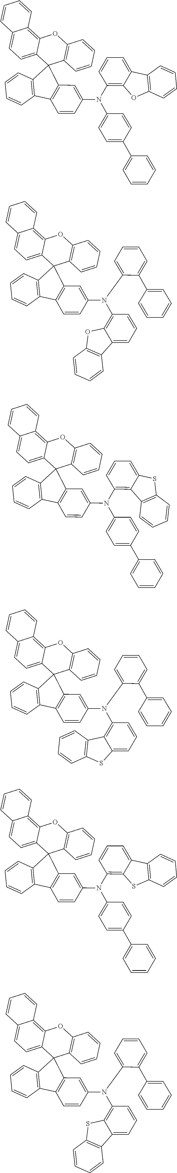
- the organic compound represented by Chemical Formula 1 may be selected from compounds represented by the following Chemical Formulas 3-1, 3-2 and 3-3, but may not be limited thereto.
- one of X 1 and X 2 is O or S, and the other one is selected from the group consisting of a single bond, C(R 5 )(R 6 ), O and S.
- R 3 and Ry are the functional group represented by Chemical Formula 2.
- L 1 , L 2 and L 3 are single bonds, and Ar 1 and Ar 2 are connected to each other to form a hetero condensation ring (a fused ring).
- a group in which Ar 1 and Ar 2 are connected to each other to form a fused ring may be represented by the following Chemical Formula 4 but may not be limited thereto.
- Ry and R 5 are the same as or different from each other, and each independently selected from the group consisting of hydrogen, deuterium, substituted or unsubstituted C 1 -C 20 alkyl groups, substituted or unsubstituted C 2 -C 20 alkenyl groups, substituted or unsubstituted C 2 -C 24 alkynyl groups, substituted or unsubstituted C 1 -C 20 alkoxy groups, substituted or unsubstituted C 1 -C 20 alkyl amine groups, substituted or unsubstituted C 1 -C 20 alkyl silyl groups, substituted or unsubstituted C 1 -C 20 alkoxy silyl groups, substituted or unsubstituted C 3 -C 30 cycloalkyl silyl groups, substituted or unsubstituted C 5 -C 30 aryl silyl groups, substituted or unsubstituted C 5 -C 30 aryl groups, substituted or un
- a and b are each independently an integer of 0 to 4.
- one of X 1 and X 2 may be O or S and the other one may be a single bond.
- X 1 may be O or S and X 2 may be a single bond, and such an organic compound may be selected from the following group.
- X 1 may be a single bond and X 2 may be O or S, and such an organic compound may be selected from the following group.
- X 1 may be O or S and X 2 may be C(CH 3 ) 2 .
- Such an organic compound may be selected from the following group.
- X 1 may be C(CH 3 ) 2 and X 2 may be O or S.
- Such an organic compound may be selected from the following group.
- the organic compound represented by Chemical Formula 1 according to an exemplary embodiment of the present disclosure has hole transport properties and electron blocking properties. Therefore, the organic compound represented by Chemical Formula 1 may be included in a hole transport layer or an electron blocking layer among a plurality of organic layers disposed between an anode and a cathode of an organic light emitting display device, thereby providing high luminous efficiency and long lifetime. This will be described later.
- FIG. 1 is a schematic cross-sectional view of an organic light emitting display device according to an exemplary embodiment of the present disclosure
- FIG. 2 is an enlarged view of a portion “X” in FIG. 1 .
- an organic light emitting display device 100 includes a substrate 110 , a thin film transistor 120 and an organic light emitting element 140 .
- the organic light emitting element 140 includes a red organic light emitting element 140 R formed in a red sub-pixel R, a green organic light emitting element 140 G formed in a green sub-pixel G and a blue organic light emitting element 140 B formed in a blue sub-pixel B.
- Each of the organic light emitting elements 140 R, 140 G and 140 B includes an anode 141 , a plurality of organic layers and a cathode 148 .
- the plurality of organic layers may have a structure in which a hole injection layer 142 , a hole transport layer 143 , an electron blocking layer 144 , a light emitting layer 145 , an electron transport layer 146 and an electron injection layer 147 are laminated.
- FIG. 1 illustrates only a red sub-pixel R, a green sub-pixel G and a blue sub-pixel B among a plurality of sub-pixels for convenience in explanation. Also, FIG. 1 illustrates that the organic light emitting display device 100 according to an exemplary embodiment of the present disclosure is driven in a top emission type. However, the present disclosure is not limited to the top emission type.
- the substrate 110 is configured to support various elements of the organic light emitting display device 100 and may be formed of an insulating material.
- the substrate may be a glass substrate or a plastic substrate.
- the plastic substrate may be made of one selected from polyethylene polyimide, polyether sulfone, naphthalate, polyethylene terephthalate and polycarbonate, but may not be limited thereto.
- a buffer layer 131 for protecting various elements of the organic light emitting display device 100 against the permeation of oxygen or moisture from the outside is disposed on the substrate 110 .
- FIG. 1 illustrates the buffer layer 131 as a single layer, the buffer layer 131 may be selectively formed as a multi-layered structure when necessary.
- the thin film transistor 120 including a gate electrode 121 , an active layer 122 , a source electrode 123 and a drain electrode 124 is disposed on the buffer layer 131 .
- the active layer 122 is disposed on the substrate 110 and a gate insulating layer 132 for insulating the active layer 122 and the gate electrode 121 is disposed on the active layer 122 .
- an interlayer insulating layer 133 for insulating the gate electrode 121 from the source electrode 123 and the drain electrode 124 is disposed on the buffer layer 131 .
- the source electrode 123 and the drain electrode 124 each in contact with the active layer 122 are formed on the interlayer insulating layer 133 .
- the thin film transistor 120 is formed in each of the red sub-pixel R, the green sub-pixel G and the blue sub-pixel B regions.
- FIG. 1 illustrates only a driving thin film transistor among various thin film transistors which may be included in the organic light emitting display device 100 for convenience in explanation. Also, FIG. 1 illustrates that the thin film transistor 120 has a coplanar structure, but may not be limited thereto. The thin film transistor 120 may have an inverted-staggered structure.
- An overcoating layer 134 may be disposed on the thin film transistor 120 .
- the overcoating layer 134 planarizes an upper part of the substrate 110 .
- the organic light emitting element 140 including the red organic light emitting element 140 R, the green organic light emitting element 140 G and the blue organic light emitting element 140 B is disposed on the overcoating layer 134 .
- the overcoating layer 134 includes a contact hole (not illustrated) for electrically connecting the thin film transistor 120 with the anode 141 of the organic light emitting element 140 .
- the anode 141 of the organic light emitting element 140 is disposed on the overcoating layer 134 .
- a bank 135 is disposed on the anode 141 and the overcoating layer 134 to divide the adjacent sub-pixel regions. Also, the bank 135 may divide pixel regions each including a plurality of sub-pixel regions.
- the blue organic light emitting element 140 B among the red organic light emitting element 140 R, the green organic light emitting element 140 G and the blue organic light emitting element 140 B will be described in detail with reference to FIG. 1 and FIG. 2 .
- the blue organic light emitting element 140 B is described as an example for convenience in explanation, but the application of the organic compound represented by Chemical Formula 1 of the present disclosure is not limited to the blue organic light emitting element 140 B.
- the blue organic light emitting element 140 B includes the anode 141 , a plurality of organic layers and the cathode 148 .
- the plurality of organic layers includes the hole injection layer 142 , the hole transport layer 143 , the electron blocking layer 144 , the light emitting layer 145 , the electron transport layer 146 and the electron injection layer 147 .
- the anode 141 is disposed on the overcoating layer 134 .
- the anode 141 is formed of a conductive material having a high work function for supplying holes to the light emitting layer 145 .
- the anode 141 may be a transparent conductive layer formed of transparent conductive oxide (TCO).
- the anode 141 may be formed of one or more transparent conductive oxides selected from indium-tin-oxide (ITO), indium-zinc-oxide (IZO), indium-tin-zinc oxide (ITZO), tin oxide (SnO 2 ), zinc oxide (Zno), indium-copper-oxide (ICO) and aluminum:zinc oxide (Al:ZnO (AZO)), but may not be limited thereto.
- ITO indium-tin-oxide
- IZO indium-zinc-oxide
- ITZO indium-tin-zinc oxide
- SnO 2 tin oxide
- Zno zinc oxide
- ICO indium-copper-oxide
- AZO aluminum:zinc oxide
- the anode 141 may be separately formed for each of the red sub-pixel R, the green sub-pixel G and the blue sub-pixel B regions. Also, sub-pixel regions may be divided by the bank 135 disposed on the anode 141 and the overcoating layer 134 .
- a reflective layer (not illustrated) may be formed under the anode.
- the reflective layer may be formed as a conductive layer having excellent reflectivity.
- the reflective layer may reflect light emitted from the light emitting layer 145 of the organic light emitting element 140 to an upper part of the organic light emitting display device 100 .
- the reflective layer may be formed of aluminum-palladium-copper alloy.
- the reflective layer may be electrically connected with the source electrode 123 of the thin film transistor 120 through the contact hole in the overcoating layer 134 .
- the hole injection layer 142 for injecting holes supplied from the anode 141 to the light emitting layer 145 is disposed on the anode 141 .
- the hole injection layer 142 is formed of a material for improving the interface characteristics between the anode 141 and the hole transport layer 143 and enabling holes to be smoothly injected to the light emitting layer 145 .
- the hole injection layer 142 may be formed of one or more compounds selected from the group consisting of HAT-CN (dipyrazino[2,3-f:2′,3′-h]quinoxaline-2,3,6,7,10,11-hexacarbonitrile), CuPc (phthalocyanine), PEDOT:PSS, NPD (N,N′-bis(naphthalene-1-yl)-N,N′-bis(phenyl)-2,2′-dimethylbenzidine), and the like, but may not be limited thereto.
- HAT-CN dipyrazino[2,3-f:2′,3′-h]quinoxaline-2,3,6,7,10,11-hexacarbonitrile
- CuPc phthalocyanine
- PEDOT:PSS phthalocyanine
- NPD N,N′-bis(naphthalene-1-yl)-N,N′-bis(phenyl)-2,2′-dimethylbenzidine
- the hole transport layer 143 for smoothly transferring holes from the hole injection layer 142 to the light emitting layer 145 is disposed on the hole injection layer 142 .
- the hole transport layer 143 may be formed of one or more compounds selected from the group consisting of NPD, TPD (N,N′-bis-(3-methylphenyl)-N,N′-bis-(phenyl)-benzidine), S-TAD (2,2′,7,7′-tetrakis(N,N-dimethylamino)-9,9-spirofluorene), PVK (poly(9-vinylcarbazole)), PPV (Poly(p-phenylenevinylene), CBP (4,4′-N,N′-dicarbazole-biphenyl), mCP (1,3-Bis(N-carbazolyl)benzene), MTDATA (4,4′,4′′-Tris(N-3-methylphenyl-N-phenyl-amino)-triphenylamine), and the like, but may not be limited thereto.
- NPD N,N′-bis-(3-methylphenyl)-N,N
- the electron blocking layer 144 containing the organic compound represented by Chemical Formula 1 is disposed on the hole transport layer 143 .
- the organic compound represented by Chemical Formula 1 has a relatively low electron affinity. Thus, it may effectively block the flow of electrons to suppress the leakage of electrons from the light emitting layer 145 to the hole transport layer 143 . Also, it may maximize the retention time of electrons in the light emitting layer 145 . That is, since the electron blocking layer 144 is formed of the organic compound represented by Chemical Formula 1, the recombination efficiency of holes and electrons in the light emitting layer 145 may be improved. As a result, the luminous efficiency and lifetime of the organic light emitting display device 100 may be greatly improved.
- the light emitting layer 145 is disposed on the electron blocking layer 144 .
- the light emitting layer 145 emits light by recombining electrons and holes therein.
- the light emitting layer 145 of the blue organic light emitting element 140 B emits blue light by recombining electrons and holes therein.
- the light emitting layer 145 is formed of a host and a dopant.
- the host of the light emitting layer 145 serves to transmit energy to the dopant in order to improve the luminous efficiency and color purity.
- the dopant is a dye organic material which is added in a small amount to the host.
- a host of the light emitting layer 145 for emitting blue light may be a beryllium-based complex but may not be limited thereto.
- a dopant of the light emitting layer 145 for emitting blue light may be selected from perylene compounds, coumarin compounds, anthracene compounds, pyrene compounds and iridium phosphorescent dopant materials, but may not be limited thereto.
- the electron transport layer 146 is disposed on the light emitting layer 145 .
- the electron transport layer 146 accelerates the transport of electrons to the light emitting layer 145 .
- the electron transport layer 146 enables electrons supplied from the cathode 148 to be readily transferred to the light emitting layer 145 .
- the electron transport layer 146 may be imidazole, oxadiazole, triazole, phenanthroline, benzoxazole, benzothiazole, benzimidazole, triazine, and derivatives thereof, but may not be limited thereto.
- the electron transport layer 146 may be selected from Liq(8-hydroxyquinolinolato-lithium), PBD (2-(4-biphenyl)-5-(4-tert-butylphenyl)-1,3,4-oxadiazole), TAZ (3-(4-biphenyl)4-phenyl-5-tert-butylphenyl-1,2,4-triazole), spiro-PBD, BCP (2,9-Dimethyl-4,7-diphenyl-1,10-phenanthroline) and BAlq (bis(2-methyl-8-quinolinolate)-4-(phenylphenolato)aluminium), but may not be limited thereto.
- a hole blocking layer may be disposed between the light emitting layer 145 and the electron transport layer 146 .
- the hole blocking layer may block the leakage of holes from the light emitting layer 145 to the electron transport layer 146 , resulting in excellent recombination efficiency of holes and electrons in the light emitting layer 145 .
- the electron blocking layer 144 may be disposed on one surface of the light emitting layer 145 and the hole blocking layer may be disposed on the other surface. In this case, holes injected from the anode 141 and electrons injected from the cathode 148 are trapped in the light emitting layer. Therefore, the recombination efficiency of electrons and holes may be further improved. Accordingly, it is possible to lower a driving voltage of the organic light emitting display device 100 and improve the luminous efficiency and luminance. Also, it is possible to improve the luminescence lifetime of the organic light emitting display device 100 .
- the electron injection layer 147 is disposed on the electron transport layer 146 .
- the electron injection layer 147 enables electrons supplied from the cathode 148 to be smoothly injected into the electron transport layer 146 .
- the electron injection layer 147 may be formed containing one or more members of BaF 2 , LiF, CsF, NaF, BaF 2 , Li 2 O, Bao, Liq (lithium quinolate) and lithium benzoate, but may not be limited thereto.
- the cathode 148 is disposed on the electron injection layer 147 .
- the cathode 148 may be formed of a metal material having a low work function for smoothly supplying electrons to the light emitting layer 145 .
- the cathode 148 may be formed of a metal material selected from Ca, Ba, Al, Ag and alloys containing one or more thereof, but may not be limited thereto.
- the cathode 148 is not patterned and formed as a single layer on the anode 141 . That is, the cathode 148 is formed as a single layer in the red sub-pixel R, the green sub-pixel G and the blue sub-pixel B regions. If the organic light emitting display device 100 is driven in the top emission type, the cathode 148 may be formed to a very small thickness and thus may be substantially transparent.
- a protection layer is formed on the cathode 148 to suppress the permeation of moisture or oxygen from the outside into the organic light emitting element.
- the protection layer may have a structure in which an inorganic layer of an inorganic insulating material and an organic layer of an organic material are laminated but may not be limited thereto.
- the protection layer may be formed by depositing a compound such as N4,N4′-bis[4-[bis(3-methylphenyl)amino]phenyl]-N4,N4′-diphenyl-[1,1′-biphenyl]-4,4′-diamine (DNTPD) or N4,N4′-diphenyl-N4,N4′-bis(4-(9-phenyl-9H-carbazol-3-yl)phenyl)-[1,1′-biphenyl]-4,4′-diamine to form a capping layer and then bonding a seal cap containing a moisture absorbent thereon using an adhesive member.
- DNTPD N4,N4′-bis[4-[bis(3-methylphenyl)amino]phenyl]-N4,N4′-diphenyl-[1,1′-biphenyl]-4,4′-diamine
- the organic light emitting display device 100 includes the organic compound represented by Chemical Formula 1 as the electron blocking layer 144 .
- the electron blocking layer 144 By blocking the leakage of electrons from the light emitting layer 145 , the recombination efficiency of electrons and holes in the light emitting layer 145 may be improved.
- all the luminous efficiency, luminance and lifetime of the organic light emitting display device 100 may be improved. Therefore, according to an exemplary embodiment of the present disclosure, it is possible to provide the organic light emitting display device 100 which has high luminous efficiency and long lifetime.
- the compound represented by Chemical Formula 1 has hole transport properties and electron blocking properties. Therefore, the compound represented by Chemical Formula 1 may be applied to a hole transport layer and/or electron blocking layer among organic layers of an organic light emitting display device.
- FIG. 3 is a cross-sectional view of a blue organic light emitting element of an organic light emitting display device according to another exemplary embodiment of the present disclosure.
- the organic light emitting display device according to another exemplary embodiment of the present disclosure is substantially the same as the exemplary embodiment illustrated in FIG. 1 and FIG. 2 except the compound represented by Chemical Formula 1 is used in a hole transport layer instead of an electron blocking layer of the blue organic light emitting element. Therefore, redundant explanation thereof will be omitted.
- the blue organic light emitting element 240 B includes the anode 141 , the hole injection layer 142 , a hole transport layer 243 , an electron blocking layer 244 , the light emitting layer 145 , the electron transport layer 146 , the electron injection layer 147 and the cathode 148 .
- the hole transport layer 243 contains the compound represented by Chemical Formula 1.
- the compound represented by Chemical Formula 1 has excellent hole transport properties and thus may easily transport holes injected from the anode 141 to the light emitting layer 145 . Therefore, the recombination efficiency of holes and electrons in the light emitting layer 145 may be improved.
- the compound represented by Chemical Formula 1 has electron blocking properties as well as the hole transport properties. Therefore, the hole transport layer 243 containing the compound represented by Chemical Formula 1 may easily transport holes injected from the anode 141 to the light emitting layer 145 . Also, the hole transport layer 243 containing the compound represented by Chemical Formula 1 may suppress the leakage of electrons, which have been injected from the cathode 148 into the light emitting layer 145 , to the hole transport layer 243 .
- the electron blocking layer 244 may contain a known electron blocking compound such as N-phenyl-N-(4-(spiro[benzo[de]anthracene-7,9′-fluoren]-2′-yl)phenyl)dibenzo[b,d]furan-4-amine, N-phenylcarbazole, polyvinylcarbazole, N,N′-bis(3-methylphenyl)-N,N′-diphenyl-[1,1-biphenyl]-4,4′-diamine or 4,4′-cyclohexylidene bis[N,N-bis(4-methylphenyl)benzenamine].
- a known electron blocking compound such as N-phenyl-N-(4-(spiro[benzo[de]anthracene-7,9′-fluoren]-2′-yl)phenyl)dibenzo[b,d]furan-4-amine, N-phenylcarbazole, polyvinyl
- the electron blocking layer 244 may be omitted as necessary.
- reaction product was purified by column chromatography and recrystallized with methanol/dichloromethane to obtain 11 g of intermediate 1-3 (4′-bromospiro(benzo[c]xanthene-7,9′-fluoren))(yield: 95%).
- reaction product was purified by column chromatography and recrystallized with methanol/dichloromethane to obtain 9.8 g of intermediate 11-3 (2′-bromospiro(benzo[c]xanthene-7,9′-fluoren))(yield: 92.4%).
- An anode made of ITO (10 nm) was formed on a substrate including an Ag alloy layer as a light reflecting layer thereon and surface-treated by irradiating N2 plasma or UV-ozone thereto. Then, 1,4,5,8,9,11-hexaazatriphenylenehexacarbonitrile (HATCN) was deposited to a thickness of 10 nm on the ITO to form a hole injection layer. Thereafter, N4,N4,N4′,N4′-tetra([1,1′-biphenyl]-4-yl)-[1,1′-biphenyl]-4,4′-diamine was deposited to a thickness of 110 nm on the hole injection layer to form a hole transport layer.
- HTCN 1,4,5,8,9,11-hexaazatriphenylenehexacarbonitrile
- Compound 1 prepared in Synthesis Embodiment 1 was deposited to a thickness of 10 nm on the hole transport layer to form an electron blocking layer. Then, while 9,10-bis(2-naphthyl) anthracene (ADN) was deposited on the electron blocking layer, 3 wt % of 2,5,8,11-tetra-butyl-perylene as a dopant was co-deposited to form a blue light emitting layer having a thickness of 25 nm. An anthracene derivative and Liq(8-Quinolinolato lithium) were mixed at a weight ratio of 1:1 and deposited to a thickness of 30 nm on the light emitting layer to form an electron transport layer.
- ADN 9,10-bis(2-naphthyl) anthracene
- Liq was deposited to a thickness of 1 nm on the electron transport layer to form an electron injection layer.
- magnesium and silver were mixed at a weight ratio of 9:1 and then deposited to a thickness of 15 nm on the electron injection layer to form a cathode.
- N4,N4′-bis[4-[bis(3-methylphenyl)amino]phenyl]-N4,N4′-diphenyl-[1,1′-biphenyl]-4,4′-diamine (DNTPD) was deposited to a thickness of 60 nm on the cathode to form a capping layer.
- a seal cap containing a moisture absorbent was bonded on the capping layer using a UV-curable adhesive, thereby manufacturing an organic light emitting element.
- Organic light emitting elements were manufactured in the same manner as in Example 1 except for using Compounds 2 to 10 synthesized in respective Synthesis Embodiment 2 to 10 as an electron blocking layer instead of using Compound 1.
- Organic light emitting elements were manufactured in the same manner as in Example 1 except for using Compound A and Compound B as an electron blocking layer instead of using Compound 1.
- the driving voltage, current efficiency, power efficiency and CIE color coordinates of the organic light emitting elements manufactured in Examples 1 to 10 and Comparative Examples 1 and 2 were measured.
- the driving voltage, current efficiency, power efficiency and CIE color coordinates 5 were measured at 10 mA/cm 2 using an electric-optical characteristic analyzer. The results are shown in Table 1 below.
- Examples 1 to 10 adopting Compounds 1 to 10 as an electron blocking layer according to an exemplary embodiment of the present disclosure have a lower driving voltage and higher current efficiency and power efficiency than Comparative Examples 1 and 2. Also, it can be seen that Examples 1 to 10 show blue color coordinates equivalent to those of Comparative Examples 1 and 2. Therefore, it can be seen that when Compounds 1 to 10 are used as an electron blocking layer, they do not influence the luminescent properties of an organic light emitting element.
- An anode made of ITO (10 nm) was formed on a substrate including an Ag alloy layer as a light reflecting layer thereon and surface-treated by irradiating N2 plasma or UV-ozone thereto. Then, 1,4,5,8,9,11-hexaazatriphenylenehexacarbonitrile (HATCN) was deposited to a thickness of 10 nm on the ITO to form a hole injection layer. Thereafter, Compound 11 prepared in Synthesis Embodiment 11 was deposited to a thickness of 100 nm on the hole injection layer to form a hole transport layer.
- HTCN 1,4,5,8,9,11-hexaazatriphenylenehexacarbonitrile
- N-phenyl-N-(4-(spiro[benzo[de]anthracene-7,9′-fluoren]-2′-yl)phenyl)dibenzo[b,d]furan-4-amine was deposited to a thickness of 10 nm on the hole transport layer to form an electron blocking layer.
- N4,N4′-diphenyl-N4,N4′-bis(4-(9-phenyl-9H-carbazol-3-yl)phenyl-[1,1′-biphenyl]-4,4′-diamine was deposited to a thickness of 60 nm on the cathode to form a capping layer.
- a seal cap containing a moisture absorbent was bonded on the capping layer using a UV-curable adhesive, thereby manufacturing an organic light emitting element.
- Organic light emitting elements were manufactured in the same manner as in Example 11 except for using Compounds 12 to synthesized in respective Synthesis Embodiment 12 to 20 as a hole transport layer instead of using Compound 11.
- Organic light emitting elements were manufactured in the same manner as in Example 11 except for using Compound C and Compound D as a hole transport layer instead of using Compound 11.
- the driving voltage, current efficiency, power efficiency and CIE color coordinates of the organic light emitting elements manufactured in Examples 11 to 20 and Comparative Examples 3 and 4 were measured.
- the driving voltage, current efficiency, power efficiency and CIE color coordinates were measured at 10 mA/cm 2 using an electric-optical characteristic analyzer. The results are shown in Table 2 below.
- Examples 11 to 20 adopting Compounds 11 to 20 as a hole transport layer according to an exemplary embodiment of the present disclosure have a lower driving voltage and higher current efficiency and power efficiency than Comparative Examples 3 and 4. Also, it can be seen that Examples 11 to 20 show blue color coordinates equivalent to those of Comparative Examples 3 and 4. Therefore, it can be seen that when Compounds 11 to 20 are used as a hole transport layer, they do not influence the luminescent properties of an organic light emitting element.
- the organic compound represented by Chemical Formula 1 of the present disclosure may lower driving voltage and improve current efficiency and power efficiency without influencing the luminescent properties of the organic light emitting element. Accordingly, it is possible to provide an organic light emitting element with high luminous efficiency and long lifetime.
- L 1 , L 2 and L 3 may be the same as or different from each other, and each independently may be selected from a single bond, substituted or unsubstituted C 6 -C 18 arylene groups and substituted or unsubstituted C 3 -C 12 heteroarylene groups.
- L 1 , L 2 and L 3 may be the same as or different from each other, and each independently may be selected from a single bond, phenylene, biphenylene, terphenylene, naphthylene, phenanthrenylene, anthracenylene and carbazolylene.
- L 1 , L 2 and L 3 may be single bonds, and Ar 1 and Ar 2 may be connected to each other to form a hetero fused ring.
- the functional group represented by the above Chemical Formula 2 may be represented by the following Chemical Formula 4:
- Ar and Ar 2 may be the same as or different from each other, and each independently may be selected from substituted or unsubstituted C 6 -C 30 aryl groups, substituted or unsubstituted C 5 -C 30 heteroaryl groups and substituted or unsubstituted C 3 -C 20 cycloalkyl groups.
- Ar 1 and Ar 2 may be the same as or different from each other, and each independently may be selected from the group represented by the following Chemical Formulas:
- one of X 1 and X 2 may be O or S and the other one may be a single bond.
- the organic compound represented by Chemical Formula 1 may be selected from compounds represented by the following Chemical Formulas 3-1, 3-2 and 3-3:
- an organic light emitting display device comprising:
- the plurality of organic layers may include a hole transport layer disposed on the anode and a light emitting layer disposed on the hole transport layer, and the hole transport layer may contain the organic compound represented by Chemical Formula 1.
- the plurality of organic layers may include a hole transport layer disposed on the anode, an electron blocking layer disposed on the hole transport layer, and a light emitting layer disposed on the electron blocking layer, and the electron blocking layer may contain the organic compound represented by Chemical Formula 1.
Landscapes
- Chemical & Material Sciences (AREA)
- Organic Chemistry (AREA)
- Engineering & Computer Science (AREA)
- Materials Engineering (AREA)
- Physics & Mathematics (AREA)
- Spectroscopy & Molecular Physics (AREA)
- Electroluminescent Light Sources (AREA)
Abstract
Description

-
- wherein in the above Chemical Formula 1,
- a ring A and a ring B are different from each other and each independently substituted or unsubstituted C6-C10 arylene groups,
- X1 and X2 are the same as or different from each other, and each independently selected from the group consisting of a single bond, C(R5)(R6), O and S, and at least one of X1 and X2 is O or S,
- R1, R2, R3 and R4 are the same as or different from each other, and each independently selected from the group consisting of a functional group represented by the following Chemical Formula 2, hydrogen, deuterium, substituted or unsubstituted C1-C20 alkyl groups, substituted or unsubstituted C2-C20 alkenyl groups, substituted or unsubstituted C2-C24 alkynyl groups, substituted or unsubstituted C1-C20 alkoxy groups; substituted or unsubstituted C1-C20 alkyl amine groups, substituted or unsubstituted C1-C20 alkyl silyl groups, substituted or unsubstituted C1-C20 alkoxy silyl groups, substituted or unsubstituted C3-C30 cycloalkyl silyl groups, substituted or unsubstituted C5-C30 aryl silyl groups, substituted or unsubstituted C5-C30 aryl groups, substituted or unsubstituted C5-C30 aryl amine groups, substituted or unsubstituted C3-C30 heteroaryl groups, a halogen group, a cyano group, a carboxyl group, a carbonyl group, an amine group, a nitro group, and combinations thereof,
- one or two of R1, R2, R3 and R4 are the functional group represented by the following Chemical Formula 2,
- R5 and R6 are the same as or different from each other, and each independently selected from the group consisting of hydrogen, deuterium, substituted or unsubstituted C1-C20 alkyl groups, substituted or unsubstituted C2-C20 alkenyl groups, substituted or unsubstituted C2-C24 alkynyl groups, substituted or unsubstituted C1-C20 alkoxy groups, substituted or unsubstituted C1-C20 alkyl amine groups, substituted or unsubstituted C1-C20 alkyl silyl groups, substituted or unsubstituted C1-C20 alkoxy silyl groups, substituted or unsubstituted C3-C30 cycloalkyl silyl groups, substituted or unsubstituted C5-C30 aryl silyl groups, substituted or unsubstituted C5-C30 aryl groups, substituted or unsubstituted C5-C30 aryl amine groups, substituted or unsubstituted C3-C30 heteroaryl groups, a halogen group, a cyano group, a carboxyl group, a carbonyl group, an amine group, a nitro group, and combinations thereof,
- m and n are each independently an integer of 0 to 6,
- and p are each independently an integer of 0 to 4,
- a sum of m, n, o and p is equal to or more than 1,

and
-
- in the above Chemical Formula 2,
- L1, L2 and L3 are the same as or different from each other, and each independently selected from the group consisting of a single bond, substituted or unsubstituted C5-C30 arylene groups, substituted or unsubstituted C3-C30 heteroarylene groups, substituted or unsubstituted C1-C20 alkylene groups, substituted or unsubstituted C3-C20 cycloalkylene groups, substituted or unsubstituted. C2-C20 alkenylene groups, substituted or unsubstituted C3-C20 cycloalkenylene groups, substituted or unsubstituted C1-C20 heteroalkylene groups, substituted or unsubstituted C3-C20 heterocycloalkylene groups, substituted or unsubstituted C2-C20 heteroalkenylene groups and substituted or unsubstituted C3-C20 heterocycloalkenylene groups, and
- Ar1 and Ar2 are the same as or different from each other, and each independently selected from the group consisting of substituted or unsubstituted C5-C30 aryl groups, substituted or unsubstituted C3-C30 heteroaryl groups, substituted or unsubstituted C3-C20 cycloalkyl groups, substituted or unsubstituted C6-C30 aralkyl groups, substituted or unsubstituted C6-C30 heteroaralkyl groups and substituted or unsubstituted C5-C30 arylamino groups.
-
- a plurality of sub-pixels, wherein at least one of the plurality of sub-pixels includes an organic light emitting element including: an anode; a plurality of organic layers disposed on the anode; and a cathode disposed on the plurality of organic layers, wherein at least one of the plurality of organic layers contains an organic compound represented by Chemical Formula 1. The organic light emitting display device includes an organic layer that contains an organic compound represented by Chemical Formula 1 and thus can easily transport holes injected from an anode to a light emitting layer and effectively trap electrons in the light emitting layer.


(1) Synthesis of Intermediate 1-1


(1) Synthesis of Intermediate 11-1


| TABLE 1 | |||||||
| Current | Power | ||||||
| Electron | Driving | effi- | effi- | ||||
| blocking | voltage | ciency | ciency | ||||
| layer | (V) | (Cd/A) | (Im/W) | CIEx | CIEy | ||
| Example 1 | Compound 1 | 3.83 | 6.5 | 5.3 | 0.138 | 0.051 |
| Example 2 | Compound 2 | 3.79 | 6.3 | 5.2 | 0.138 | 0.050 |
| Example 3 | Compound 3 | 3.73 | 6.0 | 5.0 | 0.138 | 0.052 |
| Example 4 | Compound 4 | 3.71 | 5.8 | 4.9 | 0.139 | 0.048 |
| Example 5 | Compound 5 | 3.73 | 6.5 | 5.4 | 0.138 | 0.051 |
| Example 6 | Compound 6 | 3.99 | 6.3 | 5.0 | 0.138 | 0.050 |
| Example 7 | Compound 7 | 3.97 | 6.3 | 5.0 | 0.140 | 0.047 |
| Example 8 | Compound 8 | 3.92 | 6.3 | 5.0 | 0.140 | 0.046 |
| Example 9 | Compound 9 | 3.74 | 6.1 | 5.1 | 0.139 | 0.047 |
| Example 10 | Compound 10 | 3.74 | 6.3 | 5.3 | 0.139 | 0.047 |
| Comparative | Compound A | 4.05 | 4.7 | 3.7 | 0.137 | 0.048 |
| Example1 | ||||||
| Comparative | Compound B | 4.10 | 4.0 | 3.1 | 0.138 | 0.047 |
| Example2 | ||||||

| TABLE 2 | |||||||
| Current | Power | ||||||
| Hole | Driving | effi- | effi- | ||||
| transport | voltage | ciency | ciency | ||||
| layer | (V) | (Cd/A) | (Im/W) | CIEx | CIEy | ||
| Example 11 | Compound 11 | 3.88 | 6.7 | 5.4 | 0.139 | 0.046 |
| Example 12 | Compound 12 | 3.82 | 6.7 | 5.5 | 0.138 | 0.047 |
| Example 13 | Compound 13 | 3.72 | 7.5 | 6.4 | 0.135 | 0.057 |
| Example 14 | Compound 14 | 3.70 | 7.1 | 6.0 | 0.137 | 0.053 |
| Example 15 | Compound 15 | 3.74 | 7.1 | 5.9 | 0.138 | 0.050 |
| Example 16 | Compound 16 | 3.73 | 7.1 | 6.0 | 0.138 | 0.051 |
| Example 17 | Compound 17 | 3.68 | 6.7 | 5.6 | 0.138 | 0.050 |
| Example 18 | Compound 18 | 3.76 | 7.0 | 5.9 | 0.137 | 0.052 |
| Example 19 | Compound 19 | 3.71 | 6.9 | 549 | 0.137 | 0.052 |
| Example 20 | Compound 20 | 3.73 | 7.0 | 5.9 | 0.138 | 0.051 |
| Comparative | Compound C | 3.98 | 6.3 | 5.0 | 0.137 | 0.053 |
| Example3 | ||||||
| Comparative | Compound D | 3.96 | 6.5 | 4.9 | 0.137 | 0.052 |
| Example4 | ||||||

-
- wherein in the above Chemical Formula 1,
- a ring A and a ring B are different from each other and each independently substituted or unsubstituted C6-C10 arylene groups,
- X1 and X2 are the same as or different from each other, and each independently selected from the group consisting of a single bond, C(R5)(R6), O and S, and at least one of X1 and X2 is O or S,
- R1, R2, R3 and R4 are the same as or different from each other, and each independently selected from the group consisting of a functional group represented by the following Chemical Formula 2, hydrogen, deuterium, substituted or unsubstituted C1-C20 alkyl groups, substituted or unsubstituted C2-C20 alkenyl groups, substituted or unsubstituted C2-C24 alkynyl groups, substituted or unsubstituted C1-C20 alkoxy groups, substituted or unsubstituted C1-C20 alkyl amine groups, substituted or unsubstituted C1-C20 alkyl silyl groups, substituted or unsubstituted C1-C20 alkoxy silyl groups, substituted or unsubstituted C3-C30 cycloalkyl silyl groups, substituted or unsubstituted C5-C30 aryl silyl groups, substituted or unsubstituted C5-C30 aryl groups, substituted or unsubstituted C5-C30 aryl amine groups, substituted or unsubstituted C3-C30 heteroaryl groups, a halogen group, a cyano group, a carboxyl group, a carbonyl group, an amine group, a nitro group, and combinations thereof,
- one or two of R1, R2, R3 and R4 are the functional group represented by the following Chemical Formula 2,
- R5 and R6 are the same as or different from each other, and each independently selected from the group consisting of hydrogen, deuterium, substituted or unsubstituted C1-C20 alkyl groups, substituted or unsubstituted C2-C20 alkenyl groups, substituted or unsubstituted C2-C24 alkynyl groups, substituted or unsubstituted C1-C20 alkoxy groups, substituted or unsubstituted C1-C20 alkyl amine groups, substituted or unsubstituted C1-C20 alkyl silyl groups, substituted or unsubstituted C1-C20 alkoxy silyl groups, substituted or unsubstituted C3-C30 cycloalkyl silyl groups, substituted or unsubstituted C5-C30 aryl silyl groups, substituted or unsubstituted C5-C30 aryl groups, substituted or unsubstituted C5-C30 aryl amine groups, substituted or unsubstituted C3-C30 heteroaryl groups, a halogen group, a cyano group, a carboxyl group, a carbonyl group, an amine group, a nitro group, and combinations thereof,
- m and n are each independently an integer of 0 to 6,
- and p are each independently an integer of 0 to 4,
- a sum of m, n, o and p is equal to or more than 1,

and
-
- in the above Chemical Formula 2,
- L1, L2 and L3 are the same as or different from each other, and each independently selected from the group consisting of a single bond, substituted or unsubstituted C5-C30 arylene groups, substituted or unsubstituted C3-C30 heteroarylene groups, substituted or unsubstituted C1-C20 alkylene groups, substituted or unsubstituted C3-C20 cycloalkylene groups, substituted or unsubstituted C2-C20 alkenylene groups, substituted or unsubstituted C3-C20 cycloalkenylene groups, substituted or unsubstituted C1-C20 heteroalkylene groups, substituted or unsubstituted C3-C20 heterocycloalkylene groups, substituted or unsubstituted C2-C20 heteroalkenylene groups and substituted or unsubstituted C3-C20 heterocycloalkenylene groups, and
- Ar1 and Ar2 are the same as or different from each other, and each independently selected from the group consisting of substituted or unsubstituted C5-C30 aryl groups, substituted or unsubstituted C3-C30 heteroaryl groups, substituted or unsubstituted C3-C20 cycloalkyl groups, substituted or unsubstituted C6-C30 aralkyl groups, substituted or unsubstituted C6-C30 heteroaralkyl groups and substituted or unsubstituted C5-C30 arylamino groups.

and
-
- in the above Chemical Formula 4, Ry and Re may be the same as or different from each other, and each independently may be selected from the group consisting of hydrogen, deuterium, substituted or unsubstituted C1-C20 alkyl groups, substituted or unsubstituted C2-C20 alkenyl groups, substituted or unsubstituted C2-C24 alkynyl groups, substituted or unsubstituted C1-C20 alkoxy groups, substituted or unsubstituted C1-C20 alkyl amine groups, substituted or unsubstituted C1-C20 alkyl silyl groups, substituted or unsubstituted C1-C20 alkoxy silyl groups, substituted or unsubstituted C3-C30 cycloalkyl silyl groups, substituted or unsubstituted C5-C30 aryl silyl groups, substituted or unsubstituted C5-C30 aryl groups, substituted or unsubstituted C5-C30 aryl amine groups, substituted or unsubstituted C3-C30 heteroaryl groups, a halogen group, a cyano group, a carboxyl group, a carbonyl group, an amine group, a nitro group, and combinations thereof, and
- a and b may be each independently an integer of 0 to 4.


-
- and
- in the above Chemical Formulas 3-1, 3-2 and 3-3, one of X1 and X2 may be O or s, and the other one may be selected from the group consisting of a single bond, C(R5)(R6), O and S,
- at least one of R3 and R4 may be the functional group represented by Chemical Formula 2, and
- R3, R4, R5, R6, o and p may be identical to those defined in the above Chemical Formula 1.
-
- a plurality of sub-pixels,
- wherein at least one of the plurality of sub-pixels includes an organic light emitting element including:
- an anode;
- a plurality of organic layers disposed on the anode; and
- a cathode disposed on the organic layer, and
- at least one of the plurality of organic layers contains an organic compound represented by Chemical Formula 1,

and
-
- wherein in the above Chemical Formula 1,
- a ring A and a ring B are different from each other and each independently substituted or unsubstituted C6-C10 arylene groups,
- X1 and X2 are the same as or different from each other, and each independently selected from the group consisting of a single bond, C(R5)(R6), O and S, and at least one of X1 and X2 is O or S,
- R1, R2, R3 and R4 are the same as or different from each other, and each independently selected from the group consisting of a functional group represented by the following Chemical Formula 2, hydrogen, deuterium, substituted or unsubstituted C1-C20 alkyl groups, substituted or unsubstituted C2-C20 alkenyl groups, substituted or unsubstituted C2-C24 alkynyl groups, substituted or unsubstituted C1-C20 alkoxy groups, substituted or unsubstituted C1-C20 alkyl amine groups, substituted or unsubstituted C1-C20 alkyl silyl groups, substituted or unsubstituted C1-C20 alkoxy silyl groups, substituted or unsubstituted C3-C30 cycloalkyl silyl groups, substituted or unsubstituted C5-C30 aryl silyl groups, substituted or unsubstituted. C5-C30 aryl groups, substituted or unsubstituted C5-C30 aryl amine groups, substituted or unsubstituted C3-C30 heteroaryl groups, a halogen group, a cyano group, a carboxyl group, a carbonyl group, an amine group, a nitro group, and combinations thereof,
- one or two of R1, R2, R3 and R4 are the functional group represented by the following Chemical Formula 2,
- R5 and R6 are the same as or different from each other, and each independently selected from the group consisting of hydrogen, deuterium, substituted or unsubstituted C1-C20 alkyl groups, substituted or unsubstituted C2-C20 alkenyl groups, substituted or unsubstituted C2-C24 alkynyl groups, substituted or unsubstituted C1-C20 alkoxy groups, substituted or unsubstituted C1-C20 alkyl amine groups, substituted or unsubstituted C1-C20 alkyl silyl groups, substituted or unsubstituted C1-C20 alkoxy silyl groups, substituted or unsubstituted C3-C30 cycloalkyl silyl groups, substituted or unsubstituted C5-C30 aryl silyl groups, substituted or unsubstituted C5-C30 aryl groups, substituted or unsubstituted C5-C30 aryl amine groups, substituted or unsubstituted C3-C30 heteroaryl groups, a halogen group, a cyano group, a carboxyl group, a carbonyl group, an amine group, a nitro group, and combinations thereof,
- m and n are each independently an integer of 0 to 6,
- and p are each independently an integer of 0 to 4,
- a sum of m, n, o and p is equal to or more than 1,

and
-
- in the above Chemical Formula 2,
- L1, L2 and La are the same as or different from each other, and each independently selected from the group consisting of a single bond, substituted or unsubstituted C5-C30 arylene groups, substituted or unsubstituted C3-C30 heteroarylene groups, substituted or unsubstituted C1-C20 alkylene groups, substituted or unsubstituted C3-C20 cycloalkylene groups, substituted or unsubstituted C2-C20 alkenylene groups, substituted or unsubstituted C3-C20 cycloalkenylene groups, substituted or unsubstituted C1-C20 heteroalkylene groups, substituted or unsubstituted C3-C20 heterocycloalkylene groups, substituted or unsubstituted C2-C20 heteroalkenylene groups and substituted or unsubstituted C3-C20 heterocycloalkenylene groups, and
- Ar1 and Ar2 are the same as or different from each other, and each independently selected from the group consisting of substituted or unsubstituted C5-C30 aryl groups, substituted or unsubstituted C3-C30 heteroaryl groups, substituted or unsubstituted C3-C20 cycloalkyl groups, substituted or unsubstituted C6-C30 aralkyl groups, substituted or unsubstituted C6-C30 heteroaralkyl groups and substituted or unsubstituted C5-C30 arylamino groups.
Claims (20)


Applications Claiming Priority (4)
| Application Number | Priority Date | Filing Date | Title |
|---|---|---|---|
| KR10-2019-0132197 | 2019-10-23 | ||
| KR20190132197 | 2019-10-23 | ||
| KR1020200125521A KR20210048403A (en) | 2019-10-23 | 2020-09-28 | Organic compounds and organic light emitting display device having the same |
| KR10-2020-0125521 | 2020-09-28 |
Publications (2)
| Publication Number | Publication Date |
|---|---|
| US20210126200A1 US20210126200A1 (en) | 2021-04-29 |
| US12167685B2 true US12167685B2 (en) | 2024-12-10 |
Family
ID=75506493
Family Applications (1)
| Application Number | Title | Priority Date | Filing Date |
|---|---|---|---|
| US17/078,155 Active 2042-05-16 US12167685B2 (en) | 2019-10-23 | 2020-10-23 | Organic compounds and organic light emitting display device using the same |
Country Status (2)
| Country | Link |
|---|---|
| US (1) | US12167685B2 (en) |
| CN (1) | CN112694464B (en) |
Families Citing this family (1)
| Publication number | Priority date | Publication date | Assignee | Title |
|---|---|---|---|---|
| KR20230024447A (en) * | 2021-08-10 | 2023-02-21 | 삼성디스플레이 주식회사 | Light emitting device including amine compound and electronic apparatus including the light emitting device and the amine compound |
Citations (6)
| Publication number | Priority date | Publication date | Assignee | Title |
|---|---|---|---|---|
| US20120112173A1 (en) * | 2010-11-05 | 2012-05-10 | Sony Corporation | Organic el display device and method for production of the same |
| US20150333277A1 (en) * | 2013-05-15 | 2015-11-19 | Sfc Co., Ltd. | Organic light emitting compound and organic light emitting device including the same |
| CN108137527A (en) | 2015-10-07 | 2018-06-08 | 株式会社Lg化学 | New compounds and organic light-emitting diodes containing them |
| WO2019054633A1 (en) | 2017-09-12 | 2019-03-21 | 주식회사 엘지화학 | Novel heterocyclic compound and organic light-emitting device using same |
| US20190363263A1 (en) * | 2018-05-28 | 2019-11-28 | Samsung Display Co., Ltd. | Organic electroluminescence device and monoamine compound for organic electroluminescence device |
| US20210013420A1 (en) * | 2019-07-10 | 2021-01-14 | Duk San Neolux Co., Ltd. | Compound for organic electric element, organic electric element comprising the same, and electronic device thereof |
-
2020
- 2020-10-23 CN CN202011150407.4A patent/CN112694464B/en active Active
- 2020-10-23 US US17/078,155 patent/US12167685B2/en active Active
Patent Citations (7)
| Publication number | Priority date | Publication date | Assignee | Title |
|---|---|---|---|---|
| US20120112173A1 (en) * | 2010-11-05 | 2012-05-10 | Sony Corporation | Organic el display device and method for production of the same |
| US20150333277A1 (en) * | 2013-05-15 | 2015-11-19 | Sfc Co., Ltd. | Organic light emitting compound and organic light emitting device including the same |
| CN108137527A (en) | 2015-10-07 | 2018-06-08 | 株式会社Lg化学 | New compounds and organic light-emitting diodes containing them |
| US20180287068A1 (en) | 2015-10-07 | 2018-10-04 | Lg Chem, Ltd. | Novel compound and organic light emitting diode comprising same |
| WO2019054633A1 (en) | 2017-09-12 | 2019-03-21 | 주식회사 엘지화학 | Novel heterocyclic compound and organic light-emitting device using same |
| US20190363263A1 (en) * | 2018-05-28 | 2019-11-28 | Samsung Display Co., Ltd. | Organic electroluminescence device and monoamine compound for organic electroluminescence device |
| US20210013420A1 (en) * | 2019-07-10 | 2021-01-14 | Duk San Neolux Co., Ltd. | Compound for organic electric element, organic electric element comprising the same, and electronic device thereof |
Non-Patent Citations (1)
| Title |
|---|
| First Office Action and Search Report issued in corresponding CN Application No. 202011150407.4, dated Apr. 27, 2023. |
Also Published As
| Publication number | Publication date |
|---|---|
| CN112694464B (en) | 2024-04-16 |
| US20210126200A1 (en) | 2021-04-29 |
| CN112694464A (en) | 2021-04-23 |
Similar Documents
| Publication | Publication Date | Title |
|---|---|---|
| US11991926B2 (en) | Organic electroluminescent device | |
| US11950500B2 (en) | Organic light emitting diode and organic light emitting device having thereof | |
| US12378207B2 (en) | Heterocyclic compound and organic electroluminescent device comprising same | |
| US12391700B2 (en) | Organic light emitting diode and organic light emitting device including the same | |
| US10177317B2 (en) | Organic light emitting display device | |
| US20200176679A1 (en) | Organic compound and organic electroluminescent device comprising the same | |
| US20220209140A1 (en) | Organic metal compound, organic light emitting diode and organic light emitting device having the compound | |
| US20220246864A1 (en) | Novel organic compounds and organic electroluminescent device including the same | |
| US20260026230A1 (en) | Organic light emitting diode and organic light emitting device having thereof | |
| US20120286251A1 (en) | Novel compound and organic light-emitting device including the same | |
| US20250129034A1 (en) | Organic compound and organic light emitting diode comprising same | |
| US20240279158A1 (en) | Novel compound for capping layer and organic light emitting device including same | |
| US20250081841A1 (en) | Fluorene-containing triarylamine compound and organic electroluminescent device thereof | |
| US11545630B2 (en) | Compound and organic electroluminescent device comprising the same | |
| US12167685B2 (en) | Organic compounds and organic light emitting display device using the same | |
| US12540152B2 (en) | Organic metal compound, organic light emitting diode and organic light emitting device having the compound | |
| US20210384444A1 (en) | Organic light emitting device | |
| US9647216B2 (en) | Organic compound and organic light emitting diode device including the same | |
| US12497369B2 (en) | Organic compounds and organic light emitting display device using the same | |
| US12446458B2 (en) | Organometallic compound, organic light emitting diode and organic light emitting device including the organometallic compound | |
| US12581791B2 (en) | Organic light emitting diode and organic light emitting device having thereof | |
| US20240381756A1 (en) | Organic light emitting diode and organic light emitting device having thereof | |
| US9755153B2 (en) | Organic compound and organic light emitting diode device including the same | |
| US20230209988A1 (en) | Organic light emitting diode and organic light emitting display device having the same | |
| US20240244947A1 (en) | Organic light emitting diode comprising organometallic compound and plurality of host materials |
Legal Events
| Date | Code | Title | Description |
|---|---|---|---|
| AS | Assignment |
Owner name: LG DISPLAY CO., LTD., KOREA, REPUBLIC OF Free format text: ASSIGNMENT OF ASSIGNORS INTEREST;ASSIGNORS:SONG, INBUM;KIM, SANGBEOM;KIM, SUNGHOON;AND OTHERS;REEL/FRAME:054433/0052 Effective date: 20201020 |
|
| FEPP | Fee payment procedure |
Free format text: ENTITY STATUS SET TO UNDISCOUNTED (ORIGINAL EVENT CODE: BIG.); ENTITY STATUS OF PATENT OWNER: LARGE ENTITY |
|
| STPP | Information on status: patent application and granting procedure in general |
Free format text: APPLICATION DISPATCHED FROM PREEXAM, NOT YET DOCKETED |
|
| STPP | Information on status: patent application and granting procedure in general |
Free format text: DOCKETED NEW CASE - READY FOR EXAMINATION |
|
| AS | Assignment |
Owner name: LG DISPLAY CO., LTD., KOREA, REPUBLIC OF Free format text: ASSIGNMENT OF ASSIGNORS INTEREST;ASSIGNORS:PARK, SEONG-MIN;HEO, JEONGHOE;SIGNING DATES FROM 20220219 TO 20220223;REEL/FRAME:059188/0247 |
|
| AS | Assignment |
Owner name: LG DISPLAY CO., LTD., KOREA, REPUBLIC OF Free format text: ASSIGNMENT OF ASSIGNORS INTEREST;ASSIGNOR:MATERIAL SCIENCE CO., LTD.;REEL/FRAME:059734/0943 Effective date: 20220420 |
|
| STPP | Information on status: patent application and granting procedure in general |
Free format text: NON FINAL ACTION MAILED |
|
| STPP | Information on status: patent application and granting procedure in general |
Free format text: RESPONSE TO NON-FINAL OFFICE ACTION ENTERED AND FORWARDED TO EXAMINER |
|
| STPP | Information on status: patent application and granting procedure in general |
Free format text: FINAL REJECTION MAILED |
|
| STPP | Information on status: patent application and granting procedure in general |
Free format text: DOCKETED NEW CASE - READY FOR EXAMINATION |
|
| STPP | Information on status: patent application and granting procedure in general |
Free format text: NON FINAL ACTION MAILED |
|
| STPP | Information on status: patent application and granting procedure in general |
Free format text: RESPONSE TO NON-FINAL OFFICE ACTION ENTERED AND FORWARDED TO EXAMINER |
|
| STPP | Information on status: patent application and granting procedure in general |
Free format text: NOTICE OF ALLOWANCE MAILED -- APPLICATION RECEIVED IN OFFICE OF PUBLICATIONS |
|
| STPP | Information on status: patent application and granting procedure in general |
Free format text: PUBLICATIONS -- ISSUE FEE PAYMENT VERIFIED |
|
| STPP | Information on status: patent application and granting procedure in general |
Free format text: AWAITING TC RESP, ISSUE FEE PAYMENT VERIFIED |
|
| STPP | Information on status: patent application and granting procedure in general |
Free format text: PUBLICATIONS -- ISSUE FEE PAYMENT VERIFIED |
|
| STCF | Information on status: patent grant |
Free format text: PATENTED CASE |