US12158644B2 - Electronic device - Google Patents
Electronic device Download PDFInfo
- Publication number
- US12158644B2 US12158644B2 US18/336,051 US202318336051A US12158644B2 US 12158644 B2 US12158644 B2 US 12158644B2 US 202318336051 A US202318336051 A US 202318336051A US 12158644 B2 US12158644 B2 US 12158644B2
- Authority
- US
- United States
- Prior art keywords
- viewing angle
- units
- panel
- data voltage
- angle mode
- Prior art date
- Legal status (The legal status is an assumption and is not a legal conclusion. Google has not performed a legal analysis and makes no representation as to the accuracy of the status listed.)
- Active
Links
- 238000002834 transmittance Methods 0.000 claims description 35
- 239000004973 liquid crystal related substance Substances 0.000 claims description 7
- 238000010586 diagram Methods 0.000 description 12
- 230000008859 change Effects 0.000 description 5
- 239000003086 colorant Substances 0.000 description 5
- 239000002096 quantum dot Substances 0.000 description 3
- 230000008901 benefit Effects 0.000 description 2
- 230000000694 effects Effects 0.000 description 2
- 239000000463 material Substances 0.000 description 2
- 238000000034 method Methods 0.000 description 2
- OAICVXFJPJFONN-UHFFFAOYSA-N Phosphorus Chemical compound [P] OAICVXFJPJFONN-UHFFFAOYSA-N 0.000 description 1
- 239000003990 capacitor Substances 0.000 description 1
- 239000004020 conductor Substances 0.000 description 1
- 230000008878 coupling Effects 0.000 description 1
- 238000010168 coupling process Methods 0.000 description 1
- 238000005859 coupling reaction Methods 0.000 description 1
- 238000004519 manufacturing process Methods 0.000 description 1
- 238000005259 measurement Methods 0.000 description 1
- 238000012986 modification Methods 0.000 description 1
- 230000004048 modification Effects 0.000 description 1
- 230000003287 optical effect Effects 0.000 description 1
- 230000002093 peripheral effect Effects 0.000 description 1
- 230000008569 process Effects 0.000 description 1
Images


Classifications
-
- G—PHYSICS
- G09—EDUCATION; CRYPTOGRAPHY; DISPLAY; ADVERTISING; SEALS
- G09G—ARRANGEMENTS OR CIRCUITS FOR CONTROL OF INDICATING DEVICES USING STATIC MEANS TO PRESENT VARIABLE INFORMATION
- G09G5/00—Control arrangements or circuits for visual indicators common to cathode-ray tube indicators and other visual indicators
- G09G5/14—Display of multiple viewports
-
- G—PHYSICS
- G02—OPTICS
- G02F—OPTICAL DEVICES OR ARRANGEMENTS FOR THE CONTROL OF LIGHT BY MODIFICATION OF THE OPTICAL PROPERTIES OF THE MEDIA OF THE ELEMENTS INVOLVED THEREIN; NON-LINEAR OPTICS; FREQUENCY-CHANGING OF LIGHT; OPTICAL LOGIC ELEMENTS; OPTICAL ANALOGUE/DIGITAL CONVERTERS
- G02F1/00—Devices or arrangements for the control of the intensity, colour, phase, polarisation or direction of light arriving from an independent light source, e.g. switching, gating or modulating; Non-linear optics
- G02F1/01—Devices or arrangements for the control of the intensity, colour, phase, polarisation or direction of light arriving from an independent light source, e.g. switching, gating or modulating; Non-linear optics for the control of the intensity, phase, polarisation or colour
- G02F1/13—Devices or arrangements for the control of the intensity, colour, phase, polarisation or direction of light arriving from an independent light source, e.g. switching, gating or modulating; Non-linear optics for the control of the intensity, phase, polarisation or colour based on liquid crystals, e.g. single liquid crystal display cells
- G02F1/1323—Arrangements for providing a switchable viewing angle
-
- G—PHYSICS
- G02—OPTICS
- G02F—OPTICAL DEVICES OR ARRANGEMENTS FOR THE CONTROL OF LIGHT BY MODIFICATION OF THE OPTICAL PROPERTIES OF THE MEDIA OF THE ELEMENTS INVOLVED THEREIN; NON-LINEAR OPTICS; FREQUENCY-CHANGING OF LIGHT; OPTICAL LOGIC ELEMENTS; OPTICAL ANALOGUE/DIGITAL CONVERTERS
- G02F1/00—Devices or arrangements for the control of the intensity, colour, phase, polarisation or direction of light arriving from an independent light source, e.g. switching, gating or modulating; Non-linear optics
- G02F1/01—Devices or arrangements for the control of the intensity, colour, phase, polarisation or direction of light arriving from an independent light source, e.g. switching, gating or modulating; Non-linear optics for the control of the intensity, phase, polarisation or colour
- G02F1/13—Devices or arrangements for the control of the intensity, colour, phase, polarisation or direction of light arriving from an independent light source, e.g. switching, gating or modulating; Non-linear optics for the control of the intensity, phase, polarisation or colour based on liquid crystals, e.g. single liquid crystal display cells
- G02F1/133—Constructional arrangements; Operation of liquid crystal cells; Circuit arrangements
- G02F1/1333—Constructional arrangements; Manufacturing methods
- G02F1/1335—Structural association of cells with optical devices, e.g. polarisers or reflectors
- G02F1/1336—Illuminating devices
- G02F1/133602—Direct backlight
- G02F1/133603—Direct backlight with LEDs
Definitions
- the disclosure relates to an electronic device, and in particular to an electronic device having a viewing angle switchable panel.
- the disclosure provides an electronic device having a viewing angle switchable panel, which can provide a good privacy protection effect and display quality at the same time.
- the electronic device of the disclosure includes a display module, a viewing angle switchable panel, a switching element, and a driving element.
- the display module has multiple first units and multiple second units.
- the first units have a first color.
- the second units have a second color.
- the first color and the second color are different.
- the switching element is coupled to the viewing angle switchable panel and is used to switch the viewing angle switchable panel between a first viewing angle mode and a second viewing angle mode.
- the driving element is coupled to the display module and is used to provide a first data voltage to at least one of the first units of the display module in the first viewing angle mode, and provide a second data voltage to the at least one of the first units in the second viewing angle mode. The first data voltage and the second data voltage are different.
- the electronic device of the disclosure can correspondingly adjust the data voltage provided to the display module according to the viewing angle mode of the viewing angle switchable panel, so as to effectively improve a color shift of the display module in the case where the viewing angle switchable panel operates in a privacy protection mode.
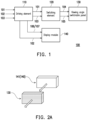
- FIG. 1 is a schematic diagram of a circuit of an electronic device according to an embodiment of the disclosure.
- FIG. 2 A is a schematic diagram of an arrangement of a display module and a viewing angle switchable panel according to an embodiment of the disclosure.
- FIG. 2 B is a schematic diagram of an arrangement of a display module and a viewing angle switchable panel according to another embodiment of the disclosure.
- FIG. 2 C is a schematic diagram of an arrangement of a display module and a viewing angle switchable panel according to yet another embodiment of the disclosure.
- FIG. 3 is a flowchart of an operation of an electronic device according to an embodiment of the disclosure.
- FIG. 4 is a schematic diagram of a relationship between transmittance and data voltage according to an embodiment of the disclosure.
- FIG. 5 is a schematic diagram of a gamma curve according to an embodiment of the disclosure.
- FIG. 6 is a flowchart of adjusting a gamma code according to an embodiment of the disclosure.
- connection and “interconnection”, unless otherwise defined, may mean that two structures are in direct contact, or may also mean that two structures are not in direct contact, wherein there is another structure disposed between the two structures.
- the terms related to bonding and connection may also include the case where the two structures are both movable or the two structures are both fixed.
- the term “coupling” includes any direct or indirect means of electrical connection.
- the measurement manner of thickness, length, and width may adopt an optical microscope (OM), and the thickness or the width may be measured by a cross-sectional image in an electron microscope, but not limited thereto.
- OM optical microscope
- the term “a given range is from a first value to a second value” or “a given range is within a range from a first value to a second value” means that the given range includes the first value, the second value, and other values in between.
- an angle between the first direction and the second direction may be between 80 degrees and 100 degrees; and if the first direction is parallel to the second direction, the angle between the first direction and the second direction may be between 0 degrees and 10 degrees.
- An electronic device of the disclosure may include, for example, a display device, an antenna device, a sensing device, a touch electronic device (touch display), a curved electronic device (curved display), or a non-rectangular electronic device (free shape display), or may be a bendable or flexible splicing electronic device, but not limited thereto.
- a light emitting unit of the electronic device may include, for example, a light emitting diode (LED), liquid crystal, fluorescence, phosphor, quantum dot (QD), other suitable display media, or a combination of the above, but not limited thereto.
- the light emitting diode may include, for example, an organic light emitting diode (OLED), an inorganic light emitting diode, a mini LED, a micro LED, a quantum dot light emitting diode (QLED or QDLED), other suitable materials, or any combination of the above, but not limited thereto.
- the antenna device may be, for example, a liquid crystal antenna, but not limited thereto. It should be noted that the electronic device of the disclosure may be any combination of the above, but not limited thereto.
- the shape of the electronic device may be rectangular, circular, polygonal, a shape with curved edges, or other suitable shapes.
- the electronic device may have a driving system, a control system, a light source system, a shelf system, etc., and other peripheral systems to support the display device or the antenna device.
- FIG. 1 is a schematic diagram of a circuit of an electronic device according to an embodiment of the disclosure.
- an electronic device 100 includes a driving element 110 , a switching element 120 , a viewing angle switchable panel 130 , and a display module 140 .
- the driving element 110 is coupled to the switching element 120 and the display module 140 .
- the switching element 120 is coupled to the viewing angle switchable panel 130 and is used to switch the viewing angle switchable panel 130 between a first viewing angle mode and a second viewing angle mode.
- the driving element 110 may receive an input voltage 101 , a display signal 102 , and a control signal 103 .
- the driving element 110 may output the input voltage 101 and the control signal 103 to the switching element 120 .
- the switching element 120 may output an operation signal 104 and a clock signal 105 to the viewing angle switchable panel 130 according to the input voltage 101 and the control signal 103 .
- the driving element 110 may also generate a first data voltage 106 or a second data voltage 107 according to the control signal 103 .
- the first data voltage and the second data voltage are different.
- the driving element 110 may output the display signal 102 and the first data voltage 106 or the second data voltage 107 to the display module 140 to drive the display module 140 .
- the first data voltage may be greater than the second data voltage.
- the second data voltage may be greater than the first data voltage.
- the driving element 110 may be, for example, a microcontroller (MCU).
- the switching element 120 may be a control circuit of the viewing angle switchable panel 130 and may be used to determine whether the viewing angle switchable panel 130 operates in the first viewing angle mode or the second viewing angle mode according to the control signal 103 , so as to output the operation signal 104 and the clock signal 105 to the viewing angle switchable panel 130 .
- the viewing angle switchable panel 130 may be a privacy protection panel and may be, for example, a liquid crystal panel. The viewing angle switchable panel 130 is integrated (laminated together) with the display module 140 .
- the viewing angle switchable panel 130 may switch to operate in different viewing angle modes according to the change of at least one of the operation signal 104 and the clock signal 105 .
- the viewing angle switchable panel 130 may change an arrangement direction of liquid crystals according to at least one of the operation signal 104 and the clock signal 105 to change a visible range.
- a first viewing angle corresponding to the first viewing angle mode is greater than a second viewing angle corresponding to the second viewing angle mode.
- the first viewing angle mode may be, for example, a sharing mode (also referred to as a wide viewing angle mode), and the display module 140 may have the first viewing angle of close to 180 degrees.
- the second viewing angle mode may be, for example, a privacy protection mode (also referred to as a narrow viewing angle mode), and the display module 140 may have, for example, the second viewing angle of 50 degrees. It should be noted that the viewing angle may refer to, for example, an included angle between a left border and a right border of the visible range.
- the display module 140 may have multiple first units and multiple second units.
- the first units may have a first color
- the second units may have a second color, wherein the first color and the second color are different.
- the first units may be red, green, blue, or other colors, and the disclosure is not limited thereto.
- the second units may be red, green, blue, or other colors, and the disclosure is not limited thereto.
- the first units have the same color
- the second units have the same color.
- the first units and the second units have different colors.
- the driving element 110 may provide the first data voltage to at least one of the first units of the display module 140 in the first viewing angle mode, and provide the second data voltage to the at least one of the first units in the second viewing angle mode, wherein the first data voltage and the second data voltage are different.
- the first units and the second units may refer to, for example, multiple sub-pixels in a panel.
- the driving element 110 may correspondingly change the data voltage of at least one of the sub-pixels driving the display module 140 .
- FIG. 2 A is a schematic diagram of an arrangement of a display module and a viewing angle switchable panel according to an embodiment of the disclosure.
- the display module 140 of FIG. 1 may include, for example, a display panel 141 of FIG. 2 A .
- the display panel 141 may include multiple first units and multiple second units, wherein the first units may be multiple first sub-pixels, and the second units may be multiple second sub-pixels.
- the display panel 141 may be a self-luminous display panel, such as a micro light emitting diode (micro LED) panel, a mini LED panel, or an organic light emitting diode (OLED) panel.
- micro LED micro light emitting diode
- OLED organic light emitting diode
- the viewing angle switchable panel 130 may be disposed before a light emitting surface of the display panel 141 , so that the display light emitted by the display panel 141 may pass through the viewing angle switchable panel 130 .
- the visible range of the display light emitted by the display panel 141 can be effectively changed.
- at least one of the first units of the display panel 141 of the embodiment may be driven by using different data voltages in the first viewing angle mode and the second viewing angle mode, so as to effectively improve a color shift caused by the display light emitted by a display panel 141 ′′ after passing through the viewing angle switchable panel 130 .
- FIG. 2 B is a schematic diagram of an arrangement of a display module and a viewing angle switchable panel according to another embodiment of the disclosure.
- the display module 140 of FIG. 1 may include, for example, a display panel 141 ′ and a light source element 142 of FIG. 2 B .
- the display panel 141 ′ may be, for example, a liquid crystal display (LCD) panel
- the light source element 142 may be, for example, a backlight source of a light emitting diode (LED) providing white light or a backlight source of an RGB light emitting diode (LED) providing a color light source.
- LED light emitting diode
- the display panel 141 ′ may include multiple first units and multiple second units, wherein the first units may be multiple first sub-pixels, and the second units may be multiple second sub-pixels.
- the light source element 142 may include multiple first units and multiple second units, and the first units and the second units respectively correspond to multiple sub-pixels of the display panel 141 ′.
- the first units may include multiple first light emitting diodes
- the second units may include multiple second light emitting diodes
- the first light emitting diodes and the second light emitting diodes may have different colors.
- different first data voltage and second data voltage are provided for the same first unit in different viewing angle modes, so that the same first unit may have different brightness.
- the display panel 141 ′ may be disposed between the viewing angle switchable panel 130 and the light source element 142 .
- the viewing angle switchable panel 130 may be disposed before a light emitting surface of the display panel 141 ′, and the display panel 141 ′ may be disposed before a light emitting surface of the light source element 142 , so that the display light emitted by the light source element 142 may pass through the display panel 141 ′ and the viewing angle switchable panel 130 .
- the viewing angle switchable panel 130 operates in the first viewing angle mode and/or the second viewing angle mode, the visible range of the display light emitted by the display panel 141 ′ can be effectively changed.
- At least one of the first units of the display panel 141 ′ or the light source element 142 of the embodiment may be driven by using different data voltages in the first viewing angle mode and the second viewing angle mode, so as to effectively improve a color shift caused by the display light emitted the display panel 141 ′′ after passing through the viewing angle switchable panel 130 .
- FIG. 2 C is a schematic diagram of an arrangement of a display module and a viewing angle switchable panel according to yet another embodiment of the disclosure.
- the display module 140 of FIG. 1 may include, for example, the display panel 141 ′′ and a light source element 142 ′ of FIG. 2 C .
- the display panel 141 ′′ may be, for example, a liquid crystal display (LCD) panel
- the light source element 142 ′ may be, for example, a backlight source of a light emitting diode (LED) providing white light or a backlight source of an RGB light emitting diode (LED) providing a color light source.
- LED light emitting diode
- the display panel 141 ′′ may include multiple first units and multiple second units, wherein the first units may be multiple first sub-pixels, and the second units may be multiple second sub-pixels.
- the light source element 142 ′ may include multiple first units and multiple second units, and the first units and the second units respectively correspond to multiple sub-pixels of the display panel 141 ′′.
- the viewing angle switchable panel 130 may be disposed between the display panel 141 ′′ and the light source element 142 ′.
- the display panel 141 ′′ may be disposed before a light emitting surface of the viewing angle switchable panel 130
- the viewing angle switchable panel 130 may be disposed before a light emitting surface of the light source element 142 ′, so that the display light emitted by the light source element 142 ′ may pass through the viewing angle switchable panel 130 .
- the viewing angle switchable panel 130 operates in the first viewing angle mode and/or the second viewing angle mode, the visible range of the display light emitted by the display panel 141 ′′ can be effectively changed.
- At least one of the first units of the display panel 141 ′′ or the light source element 142 ′ of the embodiment may be driven by using different data voltages in the first viewing angle mode and the second viewing angle mode, so as to effectively improve a color shift caused by the display light emitted by the display panel 141 ′′ after passing through the viewing angle switchable panel 130 .
- FIG. 3 is a flowchart of an operation of an electronic device according to an embodiment of the disclosure.
- the electronic device 100 may execute Step S 310 to Step S 360 below.
- Step S 310 the electronic device 100 is activated.
- Step S 320 the driving element 110 may enable the viewing angle switchable panel 130 to operate in the first viewing angle mode through the switching element 120 , and drive the display module 140 according to the first data voltage.
- the viewing angle switchable panel 130 may operate in the first viewing angle mode, such as a sharing display mode (also referred to as the wide viewing angle mode or a normal display mode), and the driving element 110 may drive at least one of the first units in the display module 140 according to the first data voltage.
- the driving element 110 may drive the first units of the display panel 141 of the display module 140 according to the first data voltage.
- the first units of the display panel 141 of the display module 140 may be, for example, sub-pixels that can emit display light.
- FIG. 4 is a schematic diagram of a relationship between transmittance and data voltage according to an embodiment of the disclosure.
- the first data voltage may be, for example, data voltages V 1 to V 9 shown in FIG. 4 , wherein the data voltages V 1 to V 9 may respectively correspond to, for example, different transmittance of 0% to 100% of the first units.
- NW normal white
- the lower the data voltage applied to the first units of the display panel 141 of the display module 140 the higher the transmittance of the first units of the display panel 141 of the display module 140 .
- the higher the data voltage applied to the first units of the display panel 141 of the display module 140 the higher the transmittance of the first units of the display panel 141 of the display module 140 .
- the lower the data voltage applied to the first units of the display panel 141 of the display module 140 the lower the transmittance of the first units of the display panel 141 of the display module 140 .
- Step S 330 the driving element 110 may judge whether to switch the viewing angle switchable panel 130 . If not, Step S 340 is executed, so that the viewing angle switchable panel 130 may continue to operate in the first viewing angle mode, and continue to drive the display module 140 according to the first data voltage. If yes, Step S 350 is executed. In Step S 350 , the driving element 110 may enable the viewing angle switchable panel 130 to operate in the second viewing angle mode through the switching element 120 , and drive the display module 140 according to the second data voltage.
- the second data voltage may be, for example, data voltages V 3 ′ to V 11 ′ shown in FIG. 4 .
- the driving element 110 may adjust a gamma code for driving the display panel 141 , so that the first data voltages V 1 to V 9 for driving the first units of the display panel 141 of the display module 140 are adjusted to second data voltages V 1 ′ to V 9 ′, and the second data voltage V 10 ′ and the second data voltage V 11 ′ corresponding to, for example, the transmittance of 88% and the transmittance of 100% may be added.
- the second data voltage V 1 ′ and the second data voltage V 2 ′ are not shown in the drawing, the second data voltage V 1 ′ and the second data voltage V 2 ′ may be analogized to both be the highest data voltages and both correspond to the transmittance of 0%. As such, each of the second data voltages V 1 ′ to V 9 ′ may be respectively higher than a corresponding one of the first data voltages V 1 to V 9 .
- the first data voltage V 7 may be 1.5 volts (V)
- the adjusted first data voltage V 7 ′ may be 1.8 volts (V).
- the driving element 110 drives the first units of the display panel 141 of the display module 140 by using the first data voltage V 7 to implement the transmittance of 75%.
- the driving element 110 may automatically switch to driving the first units of the display panel 141 of the display module 140 by using the second data voltage V 7 ′ to implement the transmittance of 50%.
- the display panel 141 may automatically reduce the transmittance of the overall display.
- FIG. 5 is a schematic diagram of a gamma curve according to an embodiment of the disclosure.
- the first data voltages V 1 to V 9 respectively corresponding to the transmittance of 0%, 13%, 25%, 38%, 50%, 63%, 75%, 88%, and 100% are changed to the second data voltages V 1 ′ to V 9 ′, and the second data voltage V 10 ′ and the second data voltage V 11 ′ corresponding to, for example, the transmittance of 88% and the transmittance of 100% may be added.
- the second data voltage V 1 ′ and the second data voltage V 2 ′ are not shown in the drawing, the second data voltage V 1 ′ and the second data voltage V 2 ′ may be analogized to both be the highest data voltages and both correspond to the transmittance of 0%. Therefore, for example, the original data voltage V 7 driving the first units of the display panel 141 of the display module 140 enables the first units of the display panel 141 of the display module 140 to operate in a state with the transmittance of 75% and to have, for example, a grayscale value of 224.
- the first units of the display panel 141 of the display module 140 may be operated in a state with the transmittance of 50% and have, for example, a grayscale value of 184.
- the display panel 141 may automatically reduce the grayscale value of the overall display (that is, achieve the effect of reducing the transmittance).
- the transmittance (or the grayscale value) of the first units of the display module 140 in the second viewing angle mode is lower than the transmittance (or the grayscale value) in the first viewing angle mode).
- the driving element 110 may adjust the gamma code for driving the first units of the display panel 141 of the display module 140 , and not adjust the gamma code for driving the second units of the display panel 141 of the display module 140 . As such, in the first viewing angle mode and the second viewing angle mode, the driving element 110 may provide the same data voltage to the second units of the display panel 141 of the display module 140 .
- the second units of the display panel 141 of the display module 140 may have the same transmittance (or grayscale value) in the first viewing angle mode and the second viewing angle mode. In this way, under different viewing angles, the transmittance is adjusted for the first units, but not for the second units.
- Step S 360 the driving element 110 may judge whether to switch the viewing angle switchable panel 130 . If not, Step S 350 is executed, so that the viewing angle switchable panel 130 may continue to operate in the second viewing angle mode, and continue to drive the display module 140 according to the second data voltage. If yes, Step S 340 is executed, so that the viewing angle switchable panel 130 operates in the first viewing angle mode, and drives the display module 140 according to the first data voltage. Therefore, the driving element 110 of the embodiment may automatically and correspondingly adjust the transmittance (or the grayscale value) of the first units of the display panel 141 of the display module 140 according to whether the viewing angle switchable panel 130 operates in the first viewing angle mode or the second viewing angle mode.
- the first units of the display panel 141 of the display module 140 are illustrated by taking, for example, blue as an example, but the disclosure is not limited thereto.
- the first unit is a blue unit, such as a blue sub-pixel in the display panel 141
- the second unit of the display panel 141 of the display module 140 may be, for example, a red sub-pixel or a green sub-pixel.
- the viewing angle switchable panel 130 operates in the first viewing angle mode (for example, the wide viewing angle mode), for example, the first data voltage V 7 (as shown in FIG. 4 ) may be provided to the blue unit of the display panel 141 , so that the blue unit is operated in a state with normal transmittance (or normal grayscale value).
- the viewing angle switchable panel 130 When the viewing angle switchable panel 130 operates in the second viewing angle mode (for example, the narrow viewing angle mode), if the same first data voltage V 7 is still provided to the blue unit, the light emission of the blue unit may be affected by the viewing angle switchable panel 130 , causing a bluish color shift in the light emission.
- the second data voltage in the second viewing angle mode, is provided to the first units, and the second data voltage is greater than the first data voltage.
- the second data voltage V 7 ′ (V 5 ) is provided to the blue unit of the display panel 141 . As shown in FIG.
- the second data voltage V 7 ′ (V 5 ) is greater than the first data voltage V 7 , the first data voltage V 7 corresponds to higher transmittance (75%), and the second data voltage V 5 corresponds to lower transmittance (50%).
- the first unit for example, the blue unit
- the first unit may be correspondingly operated in a state with lower transmittance (or a lower grayscale value) to reduce the brightness of the blue display light emitted by the display panel 141 , so as to effectively reduce or eliminate the blue color shift of the display light.
- different first data voltage and second data voltage are provided for the same first unit in different viewing angle modes, so that the same first unit can have different transmittance.
- the first unit is taken as an example for illustration.
- the data voltage may be adjusted for units with two different colors according to requirements.
- a third data voltage may be provided for at least one of the second units of the display module in the first viewing angle mode
- a fourth data voltage may be provided for the same second unit in the second viewing angle mode, wherein the third data voltage and the fourth data voltage are different.
- different third data voltage and fourth data voltage are provided for the same second unit, so that the same second unit can have different transmittance.
- different third data voltage and fourth data voltage are provided for the same second unit, so that the same second unit can have different brightness. Similar to the first unit, data voltages of other units in the display module may also be adjusted according to requirements, which will not be repeated here.
- FIG. 6 is a flowchart of adjusting a gamma code according to an embodiment of the disclosure.
- the electronic device 100 of the embodiment may execute, for example, Steps S 610 to S 660 below before the equipment leaves the factory to adjust the gamma code.
- the driving element 110 may first enable the viewing angle switchable panel to operate in the first viewing angle mode, and drive the display module 140 according to the first data voltage.
- the display module 140 may be measured by a chromaticity measuring device to obtain a first chromaticity value.
- the driving element 110 may enable the viewing angle switchable panel to operate in the second viewing angle mode, and drive the display module 140 according to the second data voltage.
- the display module 140 may be measured by the chromaticity measuring device to obtain a second chromaticity value.
- the gamma code may be adjusted according to the first chromaticity value and the second chromaticity value. As such, the gamma code for driving the first units of the display module 140 may be modified according to, for example, a difference value between the first chromaticity value and the second chromaticity value.
- the driving element 110 may store the adjusted gamma code.
- the first units of the display module 140 may drive the display module 140 by using different data voltages by the gamma code stored in the driving element 110 in the first viewing angle mode and the second viewing angle mode. In this way, a color shift caused by the display light emitted by the display module 140 after passing through the viewing angle switchable panel 130 due to the change of the visible range (the viewing angle) of the viewing angle switchable panel 130 can be effectively improved.
- any electronic device may judge whether to adopt the technical solutions provided by the disclosure according to whether the electronic device is equipped with a viewing angle switchable panel, and whether a driving element of the electronic device can switch the output of a gamma code or whether a display module can receive different gamma codes after the visible range of the viewing angle switchable panel changes.
- the driving element may be used to provide different data voltages for the first units of the display module in different viewing angle modes. In this way, the color shift of the display module caused by different viewing angle modes can be improved.
- the electronic device may correspondingly adjust the driving voltage for driving at least one of the color sub-pixels of the display module according to whether the viewing angle switchable panel operates in the sharing mode or the privacy protection mode, so as to effectively improve the color shift caused by the display light emitted by the display module after passing through the viewing angle switchable panel. Therefore, the electronic device of the disclosure can provide a good privacy protection and display quality at the same time.
Landscapes
- Physics & Mathematics (AREA)
- Nonlinear Science (AREA)
- General Physics & Mathematics (AREA)
- Chemical & Material Sciences (AREA)
- Crystallography & Structural Chemistry (AREA)
- Optics & Photonics (AREA)
- Engineering & Computer Science (AREA)
- Mathematical Physics (AREA)
- Computer Hardware Design (AREA)
- Theoretical Computer Science (AREA)
- Liquid Crystal Display Device Control (AREA)
- Liquid Crystal (AREA)
Abstract
Description
Claims (11)
Applications Claiming Priority (2)
| Application Number | Priority Date | Filing Date | Title |
|---|---|---|---|
| CN202210890057.8 | 2022-07-27 | ||
| CN202210890057.8A CN117524170A (en) | 2022-07-27 | 2022-07-27 | electronic device |
Publications (2)
| Publication Number | Publication Date |
|---|---|
| US20240036368A1 US20240036368A1 (en) | 2024-02-01 |
| US12158644B2 true US12158644B2 (en) | 2024-12-03 |
Family
ID=89665267
Family Applications (1)
| Application Number | Title | Priority Date | Filing Date |
|---|---|---|---|
| US18/336,051 Active US12158644B2 (en) | 2022-07-27 | 2023-06-16 | Electronic device |
Country Status (2)
| Country | Link |
|---|---|
| US (1) | US12158644B2 (en) |
| CN (1) | CN117524170A (en) |
Families Citing this family (1)
| Publication number | Priority date | Publication date | Assignee | Title |
|---|---|---|---|---|
| WO2025196035A2 (en) * | 2024-03-21 | 2025-09-25 | BHTC GmbH | Display device, in particular for a vehicle, for displaying information |
Citations (8)
| Publication number | Priority date | Publication date | Assignee | Title |
|---|---|---|---|---|
| US20070176887A1 (en) * | 2006-01-31 | 2007-08-02 | Uehara Shin-Ichi | Display device, terminal device, and display panel |
| US20080002103A1 (en) * | 2006-06-29 | 2008-01-03 | Sang Yun Lee | Liquid crystal display driving system having light emitting diodes |
| US20100053136A1 (en) * | 2006-12-06 | 2010-03-04 | Sharp Kabushiki Kaisha | Gradation voltage correction system and display device using the same |
| US20100253891A1 (en) * | 2007-12-05 | 2010-10-07 | Kazuyoshi Fujioka | Liquid crystal display device |
| TW201827894A (en) | 2017-01-25 | 2018-08-01 | 揚昇照明股份有限公司 | Viewing angle switchable display apparatus |
| CN110582806A (en) | 2018-08-03 | 2019-12-17 | 昆山龙腾光电股份有限公司 | Liquid crystal display device having a plurality of pixel electrodes |
| US20200257155A1 (en) * | 2017-01-12 | 2020-08-13 | Boe Technology Group Co., Ltd. | Display device and control method thereof |
| US20210063783A1 (en) * | 2019-09-02 | 2021-03-04 | Samsung Electronics Co., Ltd. | Electronic apparatus for controlling passenger seat display and method of controlling passenger seat display |
-
2022
- 2022-07-27 CN CN202210890057.8A patent/CN117524170A/en active Pending
-
2023
- 2023-06-16 US US18/336,051 patent/US12158644B2/en active Active
Patent Citations (8)
| Publication number | Priority date | Publication date | Assignee | Title |
|---|---|---|---|---|
| US20070176887A1 (en) * | 2006-01-31 | 2007-08-02 | Uehara Shin-Ichi | Display device, terminal device, and display panel |
| US20080002103A1 (en) * | 2006-06-29 | 2008-01-03 | Sang Yun Lee | Liquid crystal display driving system having light emitting diodes |
| US20100053136A1 (en) * | 2006-12-06 | 2010-03-04 | Sharp Kabushiki Kaisha | Gradation voltage correction system and display device using the same |
| US20100253891A1 (en) * | 2007-12-05 | 2010-10-07 | Kazuyoshi Fujioka | Liquid crystal display device |
| US20200257155A1 (en) * | 2017-01-12 | 2020-08-13 | Boe Technology Group Co., Ltd. | Display device and control method thereof |
| TW201827894A (en) | 2017-01-25 | 2018-08-01 | 揚昇照明股份有限公司 | Viewing angle switchable display apparatus |
| CN110582806A (en) | 2018-08-03 | 2019-12-17 | 昆山龙腾光电股份有限公司 | Liquid crystal display device having a plurality of pixel electrodes |
| US20210063783A1 (en) * | 2019-09-02 | 2021-03-04 | Samsung Electronics Co., Ltd. | Electronic apparatus for controlling passenger seat display and method of controlling passenger seat display |
Also Published As
| Publication number | Publication date |
|---|---|
| TW202405528A (en) | 2024-02-01 |
| CN117524170A (en) | 2024-02-06 |
| US20240036368A1 (en) | 2024-02-01 |
Similar Documents
| Publication | Publication Date | Title |
|---|---|---|
| US11448909B2 (en) | Display device | |
| US7530722B2 (en) | Illumination device, electro-optical device, and electronic apparatus | |
| EP3156841A1 (en) | Display base plate, display panel and display device | |
| JP2003157026A (en) | Display device and driving method thereof | |
| CN102722051B (en) | Display device, color filter and electronic equipment | |
| US7755597B2 (en) | Liquid crystal display device and driving method used in same | |
| US20250060636A1 (en) | Display device | |
| US20240062729A1 (en) | Display device | |
| US12158644B2 (en) | Electronic device | |
| US11353740B2 (en) | Backlight unit and display device using the same | |
| US7697089B2 (en) | Liquid crystal display apparatus | |
| KR102334243B1 (en) | Liquid crystal display device | |
| US20140110852A1 (en) | Active matrix substrate, and display device | |
| US20250199351A1 (en) | Double-sided display device and driving method thereof | |
| WO2022222912A1 (en) | Display panel and electronic device | |
| US20250130423A1 (en) | Head-up display system and vehicle system | |
| TWI915627B (en) | Electronic device | |
| CN118890931A (en) | Display panel and display device | |
| JP2008281866A (en) | Liquid crystal display | |
| US7742132B2 (en) | Liquid crystal display device with various reflective pattern arrangements | |
| US20240078951A1 (en) | Manufacturing method of multi-screen display | |
| US20240357897A1 (en) | Display panel, design method of display panel, and display device | |
| JP2006145885A (en) | Optical filter and backlight device | |
| CN118251089A (en) | Display screen | |
| WO2011132448A1 (en) | Colour filter, and display device |
Legal Events
| Date | Code | Title | Description |
|---|---|---|---|
| FEPP | Fee payment procedure |
Free format text: ENTITY STATUS SET TO UNDISCOUNTED (ORIGINAL EVENT CODE: BIG.); ENTITY STATUS OF PATENT OWNER: LARGE ENTITY |
|
| AS | Assignment |
Owner name: INNOLUX CORPORATION, TAIWAN Free format text: ASSIGNMENT OF ASSIGNORS INTEREST;ASSIGNORS:CHEN, HAO-YU;HSIEH, HONG-SHENG;WU, HSIN-CHIH;REEL/FRAME:064051/0839 Effective date: 20230414 |
|
| STPP | Information on status: patent application and granting procedure in general |
Free format text: FINAL REJECTION MAILED |
|
| STPP | Information on status: patent application and granting procedure in general |
Free format text: DOCKETED NEW CASE - READY FOR EXAMINATION |
|
| STPP | Information on status: patent application and granting procedure in general |
Free format text: NON FINAL ACTION MAILED |
|
| STPP | Information on status: patent application and granting procedure in general |
Free format text: RESPONSE TO NON-FINAL OFFICE ACTION ENTERED AND FORWARDED TO EXAMINER |
|
| STPP | Information on status: patent application and granting procedure in general |
Free format text: NOTICE OF ALLOWANCE MAILED -- APPLICATION RECEIVED IN OFFICE OF PUBLICATIONS |
|
| STCF | Information on status: patent grant |
Free format text: PATENTED CASE |