US12153199B2 - Camera module - Google Patents
Camera module Download PDFInfo
- Publication number
- US12153199B2 US12153199B2 US17/225,267 US202117225267A US12153199B2 US 12153199 B2 US12153199 B2 US 12153199B2 US 202117225267 A US202117225267 A US 202117225267A US 12153199 B2 US12153199 B2 US 12153199B2
- Authority
- US
- United States
- Prior art keywords
- module
- optical axis
- guide shaft
- housing
- reflective
- Prior art date
- Legal status (The legal status is an assumption and is not a legal conclusion. Google has not performed a legal analysis and makes no representation as to the accuracy of the status listed.)
- Active, expires
Links
Images


Classifications
-
- G—PHYSICS
- G03—PHOTOGRAPHY; CINEMATOGRAPHY; ANALOGOUS TECHNIQUES USING WAVES OTHER THAN OPTICAL WAVES; ELECTROGRAPHY; HOLOGRAPHY
- G03B—APPARATUS OR ARRANGEMENTS FOR TAKING PHOTOGRAPHS OR FOR PROJECTING OR VIEWING THEM; APPARATUS OR ARRANGEMENTS EMPLOYING ANALOGOUS TECHNIQUES USING WAVES OTHER THAN OPTICAL WAVES; ACCESSORIES THEREFOR
- G03B17/00—Details of cameras or camera bodies; Accessories therefor
- G03B17/02—Bodies
-
- G—PHYSICS
- G02—OPTICS
- G02B—OPTICAL ELEMENTS, SYSTEMS OR APPARATUS
- G02B13/00—Optical objectives specially designed for the purposes specified below
- G02B13/001—Miniaturised objectives for electronic devices, e.g. portable telephones, webcams, PDAs, small digital cameras
- G02B13/0055—Miniaturised objectives for electronic devices, e.g. portable telephones, webcams, PDAs, small digital cameras employing a special optical element
- G02B13/0065—Miniaturised objectives for electronic devices, e.g. portable telephones, webcams, PDAs, small digital cameras employing a special optical element having a beam-folding prism or mirror
-
- G—PHYSICS
- G02—OPTICS
- G02B—OPTICAL ELEMENTS, SYSTEMS OR APPARATUS
- G02B27/00—Optical systems or apparatus not provided for by any of the groups G02B1/00 - G02B26/00, G02B30/00
- G02B27/64—Imaging systems using optical elements for stabilisation of the lateral and angular position of the image
- G02B27/646—Imaging systems using optical elements for stabilisation of the lateral and angular position of the image compensating for small deviations, e.g. due to vibration or shake
-
- G—PHYSICS
- G02—OPTICS
- G02B—OPTICAL ELEMENTS, SYSTEMS OR APPARATUS
- G02B7/00—Mountings, adjusting means, or light-tight connections, for optical elements
- G02B7/18—Mountings, adjusting means, or light-tight connections, for optical elements for prisms; for mirrors
-
- G—PHYSICS
- G03—PHOTOGRAPHY; CINEMATOGRAPHY; ANALOGOUS TECHNIQUES USING WAVES OTHER THAN OPTICAL WAVES; ELECTROGRAPHY; HOLOGRAPHY
- G03B—APPARATUS OR ARRANGEMENTS FOR TAKING PHOTOGRAPHS OR FOR PROJECTING OR VIEWING THEM; APPARATUS OR ARRANGEMENTS EMPLOYING ANALOGOUS TECHNIQUES USING WAVES OTHER THAN OPTICAL WAVES; ACCESSORIES THEREFOR
- G03B17/00—Details of cameras or camera bodies; Accessories therefor
- G03B17/02—Bodies
- G03B17/12—Bodies with means for supporting objectives, supplementary lenses, filters, masks, or turrets
-
- G—PHYSICS
- G03—PHOTOGRAPHY; CINEMATOGRAPHY; ANALOGOUS TECHNIQUES USING WAVES OTHER THAN OPTICAL WAVES; ELECTROGRAPHY; HOLOGRAPHY
- G03B—APPARATUS OR ARRANGEMENTS FOR TAKING PHOTOGRAPHS OR FOR PROJECTING OR VIEWING THEM; APPARATUS OR ARRANGEMENTS EMPLOYING ANALOGOUS TECHNIQUES USING WAVES OTHER THAN OPTICAL WAVES; ACCESSORIES THEREFOR
- G03B17/00—Details of cameras or camera bodies; Accessories therefor
- G03B17/02—Bodies
- G03B17/17—Bodies with reflectors arranged in beam forming the photographic image, e.g. for reducing dimensions of camera
-
- G—PHYSICS
- G03—PHOTOGRAPHY; CINEMATOGRAPHY; ANALOGOUS TECHNIQUES USING WAVES OTHER THAN OPTICAL WAVES; ELECTROGRAPHY; HOLOGRAPHY
- G03B—APPARATUS OR ARRANGEMENTS FOR TAKING PHOTOGRAPHS OR FOR PROJECTING OR VIEWING THEM; APPARATUS OR ARRANGEMENTS EMPLOYING ANALOGOUS TECHNIQUES USING WAVES OTHER THAN OPTICAL WAVES; ACCESSORIES THEREFOR
- G03B30/00—Camera modules comprising integrated lens units and imaging units, specially adapted for being embedded in other devices, e.g. mobile phones or vehicles
-
- G—PHYSICS
- G03—PHOTOGRAPHY; CINEMATOGRAPHY; ANALOGOUS TECHNIQUES USING WAVES OTHER THAN OPTICAL WAVES; ELECTROGRAPHY; HOLOGRAPHY
- G03B—APPARATUS OR ARRANGEMENTS FOR TAKING PHOTOGRAPHS OR FOR PROJECTING OR VIEWING THEM; APPARATUS OR ARRANGEMENTS EMPLOYING ANALOGOUS TECHNIQUES USING WAVES OTHER THAN OPTICAL WAVES; ACCESSORIES THEREFOR
- G03B5/00—Adjustment of optical system relative to image or object surface other than for focusing
-
- G—PHYSICS
- G02—OPTICS
- G02B—OPTICAL ELEMENTS, SYSTEMS OR APPARATUS
- G02B7/00—Mountings, adjusting means, or light-tight connections, for optical elements
- G02B7/02—Mountings, adjusting means, or light-tight connections, for optical elements for lenses
- G02B7/04—Mountings, adjusting means, or light-tight connections, for optical elements for lenses with mechanism for focusing or varying magnification
- G02B7/08—Mountings, adjusting means, or light-tight connections, for optical elements for lenses with mechanism for focusing or varying magnification adapted to co-operate with a remote control mechanism
-
- G—PHYSICS
- G03—PHOTOGRAPHY; CINEMATOGRAPHY; ANALOGOUS TECHNIQUES USING WAVES OTHER THAN OPTICAL WAVES; ELECTROGRAPHY; HOLOGRAPHY
- G03B—APPARATUS OR ARRANGEMENTS FOR TAKING PHOTOGRAPHS OR FOR PROJECTING OR VIEWING THEM; APPARATUS OR ARRANGEMENTS EMPLOYING ANALOGOUS TECHNIQUES USING WAVES OTHER THAN OPTICAL WAVES; ACCESSORIES THEREFOR
- G03B2205/00—Adjustment of optical system relative to image or object surface other than for focusing
- G03B2205/0007—Movement of one or more optical elements for control of motion blur
Definitions
- the following description relates to a camera module.
- camera modules have been implemented in portable electronic devices including, but not limited to, smartphones.
- a thickness of the form factor of a portable electronic device has been decreased to meet market demand, and accordingly, it is necessary for the camera modules to have a reduced size.
- a camera module including a reflective member for changing a path of light has been implemented.
- a total track length (TTL) (a distance from a lens the most adjacent to an object side to an imaging plane of an image sensor) of the camera module may not affect the thickness of a portable electronic device.
- a camera module including a plurality of reflective members has also been proposed to address the issue in which a total track length of a camera module is excessively increased in one direction.
- the reflective member is configured to change a path of light
- assembly precision of the reflective member may affect quality of an image
- a camera module includes a housing; a folded module, disposed in the housing, and comprising a first reflective member; a lens module, disposed in the housing, and configured to receive light reflected from the folded module; a holder, disposed in the housing, and comprising a second reflective member configured to receive light passing through the lens module; and an image sensor, configured to receive light reflected from the second reflective member, wherein a guide shaft, disposed in the housing, is configured to be inserted into the holder.
- the holder may be configured to be rotatably inserted into the guide shaft, and is fixed to the housing by an adhesive member.
- the second reflective member may be configured to reflect light incident from the lens module in a first direction towards the image sensor in a second direction, and the guide shaft may be configured to extend in a direction perpendicular to the first direction and the second direction.
- the guide shaft may have a cylindrical shape.
- the holder may have a coupling portion having one of a hole shape and a groove shape into which the guide shaft is inserted.
- the holder may include a contact surface extending in a third direction, parallel to the guide shaft, and the second reflective member may be seated on the contact surface.
- a distance D between the guide shaft and the contact surface may be within a range satisfying the following equation: 0 ⁇ D ⁇ L/4
- the guide shaft may be injection-formed together with the housing.
- Light incident to the first reflective member in a first optical axis direction may be changed to travel in a second optical axis direction perpendicular to the first optical axis by the second reflecting member, and is incident to the lens module.
- Light passing through the lens module is changed to travel in a third optical axis direction perpendicular to the second optical axis direction by the second reflective member, to reach the image sensor.
- the third optical axis direction may be perpendicular to the first optical axis direction.
- the first reflective member or the second reflective member may include one of a mirror and a prism.
- a camera module includes a folded module, disposed in a housing, and comprising a first reflective member configured to reflect light incident in a first optical axis direction; a lens module, disposed in the housing, and configured to receive light reflected from the folded module; a holder, disposed in the housing, and comprising a second reflective member configured to reflect light passing through the lens module and incident to the holder in a second optical axis direction; and an image sensor, configured to receive light passing through the second reflective member, wherein a guide shaft, provided in the housing, is configured to be inserted into the holder, and wherein the guide shaft extends in a direction parallel to the first optical axis and perpendicular to the second optical axis.
- an electronic device includes a camera module, including a housing; a first reflective module, configured to receive light incident in a first optical axis direction, and output light in a second optical axis direction perpendicular to the first optical axis direction; a lens module, disposed in the housing, and configured to receive light from the first reflective module; a second reflective module, configured to receive light from the lens module, and output light in a third optical direction perpendicular to the first optical axis direction and the second optical axis direction; an image sensor, configured to receive light from the second reflective module; and a guide shaft, configured to fix the second reflective module to the housing, wherein the second reflective module includes a holder, and the guide shaft is configured to be inserted into the holder.
- the holder may include a contact surface extending in a third direction, parallel to the guide shaft, and a reflective member of the reflective module may be seated on the contact surface.
- a length of the contact surface in a direction perpendicular to the third direction is L, a distance D between the guide shaft and the contact surface is within a range satisfying the following equation: Equation: 0 ⁇ D ⁇ L/4.
- the first reflective module may be configured to rotate with respect to the first optical axis direction and the second optical axis direction.
- FIG. 1 is a perspective diagram illustrating an example camera module, in accordance with one or more embodiments
- FIG. 2 is a plan diagram illustrating an example camera module, in accordance with one or more embodiments
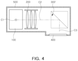
- FIGS. 3 and 4 are diagrams illustrating an example in which image quality degrades by assembly tolerance of a reflective module
- FIG. 5 is a perspective diagram illustrating a second reflective module and a guide unit of an example camera module, in accordance with one or more embodiments.
- FIG. 6 is a plan diagram illustrating an example camera module, in accordance with one or more embodiments.
- first,” “second,” and “third” may be used herein to describe various members, components, regions, layers, or sections, these members, components, regions, layers, or sections are not to be limited by these terms. Rather, these terms are only used to distinguish one member, component, region, layer, or section from another member, component, region, layer, or section. Thus, a first member, component, region, layer, or section referred to in examples described herein may also be referred to as a second member, component, region, layer, or section without departing from the teachings of the examples.
- FIG. 1 is a perspective diagram illustrating an example camera module, in accordance with one or more embodiments.
- FIG. 2 is a plan diagram illustrating an example camera module, in accordance with one or more embodiments.
- the example camera module may include a first reflective module 100 , a lens module 200 , a second reflective module 300 , an image sensor 400 , a housing 500 , and a case 600 .
- the reflective module 100 or 300 may be referred to as a folded module.
- the housing 500 may have an internal space to accommodate the components of the camera module.
- the housing 500 may have a box shape with an open upper portion.
- the housing 500 may accommodate one or more of the first reflective module 100 , the lens module 200 , the second reflective module 300 and the image sensor 400 therein.
- the first reflective module 100 , the lens module 200 , the second reflective module 300 , and the image sensor 400 may be disposed in the internal space of the housing 500 .
- FIG. 2 illustrates an example in which all the first reflective module 100 , the lens module 200 , the second reflective module 300 and the image sensor 400 are accommodated in the housing 500 .
- this illustrated arrangement is only an example.
- the first reflective module 100 may be provided separately from the housing 500 , and in this example, one side of the housing 500 may be open such that light transferred from the first reflective module 100 may pass therethrough.
- a shape of a plane of the housing 500 may have a bent shape, bent in a “ ⁇ ” shape.
- the first reflective module 100 , the lens module 200 , and the second reflective module 300 may be disposed in the internal space of the housing 500 from one side, for example, an object side, to the other side, for example, an image side
- the image sensor 400 may be disposed in a direction perpendicular to the direction from one side, for example, the object side, to the other side, for example, the image side, of the internal space of the housing 500 .
- the case 600 ( FIG. 1 ) may be coupled to the housing 500 to cover the upper portion of the housing 500 .
- the lens module 200 may be disposed in the housing 500 .
- the lens module 200 may include one or more lenses for imaging light incident to the camera module on the image sensor 400 .
- the lens module 200 may be disposed between the first reflective module 100 and the second reflective module 300 .
- the first reflective module 100 may be disposed in front of the lens module 200 , and may include a first reflective member 110 and a first holder 130 .
- the first reflective member 110 may be configured to change a direction of travel of light.
- the first reflective member 110 may be implemented by a prism or a mirror that reflects light.
- the first reflective module 100 may be configured to change an optical path as illustrated in FIGS. 1 and 2 .
- an optical path of light incident in a first optical axis C 1 direction may be changed to be directed to a second optical axis C 2 by the first reflective module 100 .
- the first optical axis C 1 and the second optical axis C 2 may intersect each other.
- the first optical axis C 1 and the second optical axis C 2 may be perpendicular to each other.
- Light of which the optical path is changed by the first reflective module 100 , may be refracted while passing through the lens module 200 .
- the camera module in the example may compensate for hand shake during imaging.
- a relative displacement corresponding to the shaking may be applied to the first reflective module 100 , thereby correcting the shaking.
- the first reflective module 100 may rotate with reference to two axes to correct the shaking that may occur during imaging.
- the second reflective module 300 may be disposed on a rear side of the lens module 200 . Additionally, the second reflective module 300 may be disposed between the lens module 200 and the image sensor 400 .
- the second reflective module 300 may include a second reflective member 310 and a second holder 330 .
- the second reflective member 310 may be configured to change a direction of travel of light.
- the second reflective member 310 may be implemented by a prism (see FIG. 2 ) or a mirror (see FIG. 6 ) which may reflect light.
- the second reflective module 300 may be configured to change the optical path of light as illustrated in FIGS. 1 and 2 .
- the optical path of light which has been changed in the second optical axis C 2 direction by the first reflective module 100 may be changed again to be directed to a third optical axis C 3 by the second reflective module 300 .
- the second optical axis C 2 and the third optical axis C 3 may intersect each other.
- the second optical axis C 2 and the third optical axis C 3 may be perpendicular to each other.
- the third optical axis C 3 may intersect with the first optical axis C 1 and the second optical axis C 2 .
- the first optical axis C 1 , the second optical axis C 2 , and the third optical axis C 3 may be perpendicular to each other.
- the first optical axis C 1 and the second optical axis C 2 may be perpendicular to each other, and the third optical axis C 3 may be perpendicular to both the first optical axis C 1 and the second optical axis C 2 .
- the first reflective module 100 and the second reflective module 300 may be configured to change an optical path in different directions.
- a travelling direction of light incident in the first optical axis C 1 direction may be changed in the second optical axis C 2 direction intersecting the first optical axis C 1 direction by the first reflective module 100 .
- a travelling direction of light in the second optical axis C 2 direction may be changed in the third optical axis C 3 direction intersecting the second optical axis C 2 direction by the second reflective module 300 .
- the optical path may be changed twice until light incident to the camera module is formed on the image sensor 400 . Accordingly, a height and a length of the camera module may be significantly reduced. Accordingly, a small-sized camera module may be provided.
- the optical path may be changed twice.
- the optical path may be changed at least twice.
- the second reflective module 300 may refer to a reflective module disposed most adjacent to the image sensor 400 among the plurality of reflective modules.
- the first reflective module 100 and the second reflective module 300 are configured to change the optical path, the first reflective module 100 and the second reflective module 300 should be assembled to the camera module with precision.
- assembly precision of the second reflective module 300 may be more important than assembly precision of the first reflective module 100 .
- the second reflective module 300 is configured to be fixed, and may change an optical path in a position adjacent to the image sensor 400 , assembly precision of the second reflective module 300 may greatly affect image quality.
- the second reflective module 300 may include a second reflective member 310 and a second holder 330 .
- the second reflective member 310 may be coupled to the second holder 330
- the second holder 330 may be coupled to the housing 500 .
- assembly precision of the second reflective module 300 may be determined according to how precisely the second holder 330 is assembled to the housing 500 .
- the housing 500 may include a guide shaft 710 (or a protrusion) extending in one direction.
- the second reflective module 300 may include a coupling portion 730 that receives at least a portion of the guide shaft 710 , and as the guide shaft 710 is inserted into the coupling portion 730 , the second reflective module 300 may be assembled to the housing 500 .
- the coupling portion 730 may have a hole shape corresponding to the guide shaft 710 .
- the coupling portion 730 may be implemented by a through-hole opened in both directions of the holder or a hole opened in a single direction.
- the guide shaft 710 may extend in a direction perpendicular to the second optical axis and the third optical axis. In an example, the guide shaft 710 may extend in a direction parallel to a reflective surface of the second reflective member 300 . In an example, the guide shaft may extend in a direction parallel to the first optical axis.
- the second holder 330 may be assembled to the housing 500 in a direction parallel to the direction in which the guide shaft 710 extends, such that the guide shaft 710 is inserted into the coupling portion 730 of the holder.
- FIGS. 3 and 4 are diagrams illustrating an example in which image quality is degraded by assembly tolerance of a reflective module.
- a focal length of the lens module 200 disposed in front of the second reflective module 300 ′ may not be affected by the position of the second reflective module 300 ′, a focus may be formed in a predetermined position irrespective of the position of the second reflective module 300 ′.
- the example camera module may include a guide unit 700 to reduce the shifting of the second reflective module 300 in the second optical axis C 2 direction and the third optical axis C 3 direction from the designed position.
- FIG. 5 is a perspective diagram illustrating a second reflective module and a guide unit of an example camera module, in accordance with one or more embodiments.
- the guide unit 700 may include a guide shaft 710 and a coupling portion 730 .
- the guide shaft 710 may be provided in the housing 500 .
- the guide shaft 710 may be injection-formed together with the housing 500 .
- the guide shaft 710 and the housing 500 may be provided as separate components, and the guide shaft 710 may be coupled to the housing 500 .
- the guide shaft 710 may have a cylindrical shape.
- the coupling portion 730 may be provided in the second reflective module 300 .
- the coupling portion 730 may be provided in the second holder 330 of the second reflective module 300 .
- the coupling portion 730 may have a hole or a groove having a shape corresponding to the guide shaft 710 .
- the coupling portion 730 When the coupling portion 730 is configured to have a hole shape, the coupling portion 730 may be disposed to penetrate a first side and a second side of the second holder 330 .
- the coupling portion 730 When the coupling portion 730 is configured to have a groove shape, the coupling portion 730 may be disposed to penetrate a first side of the second holder 330 .
- the second holder 330 may have a contact surface in contact with the second reflective member 310 , and the guide unit 700 may be spaced apart from the contact surface.
- the contact surface may extend in a direction parallel to the guide shaft 710 , and the second reflective member 310 may be mounted on the contact surface.
- a reflective surface of the second reflective member 310 may be substantially parallel to the contact surface.
- the reflective surface of the second reflecting member 310 may form an angle of approximately 45 degrees with the second and third optical axes, and accordingly, the contact surface may also form an angle of approximately 45 degrees with the second and third optical axes.
- the guide unit may be disposed adjacent to the contact surface.
- L a length of the contact surface in the direction perpendicular to a length direction of the guide unit 700
- D a distance between the guide unit 700 and the contact surface
- the second reflective module 300 may be mounted on the housing 500 by the coupling between the coupling portion 730 and the guide shaft 710 .
- the second reflective module 300 may rotate around the guide shaft 710 while being mounted on the housing 500 , a position of the second reflective module 300 may be adjusted for a focus to be formed in a desired position, and the second reflective module 300 may be fixed to the housing 500 through, as an example, an adhesive member.
- the adhesive member may be applied to a region between the second reflective module 300 and the housing 500 (or the guide shaft 710 ) in a liquid state and may be cured.
- the adhesive member may be attached to a region between the second reflective module 300 and the housing 500 (or the guide shaft 710 ).
- the camera module in the example may reduce the effect of assembly precision of the second reflective module 300 on image quality.
- the camera module may reduce sensitivity depending on assembly tolerance of the reflective member.
Landscapes
- Physics & Mathematics (AREA)
- General Physics & Mathematics (AREA)
- Optics & Photonics (AREA)
- Studio Devices (AREA)
Abstract
Description
Claims (16)
0<D<L/4. Equation:
0<D<L/4. Equation:
Applications Claiming Priority (4)
| Application Number | Priority Date | Filing Date | Title |
|---|---|---|---|
| KR20200078709 | 2020-06-26 | ||
| KR10-2020-0078709 | 2020-06-26 | ||
| KR1020200128525A KR102425752B1 (en) | 2020-06-26 | 2020-10-06 | Camera Module |
| KR10-2020-0128525 | 2020-10-06 |
Publications (2)
| Publication Number | Publication Date |
|---|---|
| US20210405333A1 US20210405333A1 (en) | 2021-12-30 |
| US12153199B2 true US12153199B2 (en) | 2024-11-26 |
Family
ID=78807049
Family Applications (1)
| Application Number | Title | Priority Date | Filing Date |
|---|---|---|---|
| US17/225,267 Active 2042-06-29 US12153199B2 (en) | 2020-06-26 | 2021-04-08 | Camera module |
Country Status (2)
| Country | Link |
|---|---|
| US (1) | US12153199B2 (en) |
| CN (2) | CN113934085B (en) |
Families Citing this family (3)
| Publication number | Priority date | Publication date | Assignee | Title |
|---|---|---|---|---|
| KR102842069B1 (en) * | 2022-09-27 | 2025-08-04 | 삼성전기주식회사 | Camera module |
| CN117255242A (en) * | 2023-09-08 | 2023-12-19 | 华为技术有限公司 | Camera modules and electronic equipment |
| US12487510B2 (en) * | 2024-02-19 | 2025-12-02 | Ningbo Sunny Opotech Co., Ltd. | Reflective module, reflective driving assembly, and camera module |
Citations (34)
| Publication number | Priority date | Publication date | Assignee | Title |
|---|---|---|---|---|
| US4432626A (en) * | 1980-12-16 | 1984-02-21 | Victor Company Of Japan, Limited | Single-lens reflex type viewfinder and method of adjusting the same |
| US5317444A (en) * | 1991-12-02 | 1994-05-31 | Brother Kogyo Kabushiki Kaisha | Light scanning apparatus |
| US5761582A (en) | 1995-10-06 | 1998-06-02 | Konica Corporation | Optical adjustment device for an image forming apparatus |
| US20070064318A1 (en) * | 2005-09-20 | 2007-03-22 | Konica Minolta Photo Imaging, Inc. | Imaging optical unit and image pickup apparatus |
| US20070109664A1 (en) * | 2005-11-15 | 2007-05-17 | Konica Minolta Photo Imaging, Inc. | Imaging optical system and image pickup apparatus |
| US20070183065A1 (en) * | 2006-02-08 | 2007-08-09 | Konica Minolta Opto, Inc. | Lens unit and image capturing apparatus |
| US20080024886A1 (en) * | 2006-07-27 | 2008-01-31 | Takashi Miyazawa | Lens frame structure |
| US20080030873A1 (en) * | 2006-08-02 | 2008-02-07 | Konica Minolta Opto, Inc. | Lens unit and photographing apparatus |
| US20080291543A1 (en) | 2007-02-26 | 2008-11-27 | Pentax Corporation | Imaging unit and mobile electronic device |
| US20090034962A1 (en) * | 2007-07-31 | 2009-02-05 | Konica Minolta Opto, Inc. | Camera module and electronic device |
| JP2009217046A (en) | 2008-03-11 | 2009-09-24 | Olympus Imaging Corp | Digital camera |
| US20120051205A1 (en) * | 2010-08-30 | 2012-03-01 | Sanyo Electric Co., Ltd. | Optical pickup apparatus |
| KR101292693B1 (en) | 2007-02-26 | 2013-08-02 | 호야 가부시키가이샤 | Imaging unit and mobile electronic device |
| CN103257427A (en) | 2012-02-16 | 2013-08-21 | 奥林巴斯映像株式会社 | Photographic device |
| US20130278785A1 (en) | 2012-04-20 | 2013-10-24 | Hoya Corporation | Imaging apparatus |
| WO2015153901A1 (en) | 2014-04-04 | 2015-10-08 | Qualcomm Incorporated | Auto-focus in low-profile folded optics multi-camera system |
| US20160044250A1 (en) | 2014-08-10 | 2016-02-11 | Corephotonics Ltd. | Zoom dual-aperture camera with folded lens |
| US20170108670A1 (en) | 2015-10-19 | 2017-04-20 | Samsung Electro-Mechanics Co., Ltd. | Optical imaging system |
| US20170131526A1 (en) | 2015-11-09 | 2017-05-11 | Samsung Electronics Co., Ltd. | Reflecting imaging apparatus and mobile device having the same |
| CN107404604A (en) * | 2017-01-16 | 2017-11-28 | 南昌欧菲光电技术有限公司 | Assemble method and camera module |
| CN107533211A (en) | 2015-04-16 | 2018-01-02 | 核心光电有限公司 | Autofocus and Optical Image Stabilization in a Compact Folding Camera |
| KR20180015966A (en) | 2016-08-04 | 2018-02-14 | 자화전자(주) | Actuator for zoom lens |
| US20180109660A1 (en) | 2016-10-13 | 2018-04-19 | Samsung Electro-Mechanics Co., Ltd. | Camera module and portable electronic device including the same |
| KR20180041040A (en) | 2016-10-13 | 2018-04-23 | 삼성전기주식회사 | Camera module and portable electronic device including the same |
| CN108139558A (en) | 2015-10-15 | 2018-06-08 | 麦克赛尔株式会社 | Projection type image display device |
| CN108432226A (en) | 2015-12-25 | 2018-08-21 | 三星电子株式会社 | Camera model and electronic device including camera model |
| CN108449540A (en) | 2018-06-15 | 2018-08-24 | Oppo广东移动通信有限公司 | Camera modules, camera components and electronics |
| CN109963058A (en) | 2017-12-14 | 2019-07-02 | Lg 电子株式会社 | Prism apparatus and camera apparatus including prism apparatus |
| US20190227199A1 (en) | 2018-01-25 | 2019-07-25 | Tdk Taiwan Corp. | Liquid optical module |
| CN110764232A (en) | 2019-11-29 | 2020-02-07 | Oppo广东移动通信有限公司 | Optical Lenses and Electronics |
| US20200057313A1 (en) | 2017-12-14 | 2020-02-20 | Lg Electronics Inc. | Prism apparatus, and camera apparatus including the same |
| CN110879454A (en) | 2019-12-25 | 2020-03-13 | Oppo广东移动通信有限公司 | Camera module, periscope camera module, camera assembly and electronic device |
| US20200137274A1 (en) | 2018-10-26 | 2020-04-30 | Samsung Electro-Mechanics Co., Ltd. | Camera module |
| CN111246070A (en) | 2020-03-18 | 2020-06-05 | 南昌欧菲光电技术有限公司 | Camera module and electronic equipment |
-
2021
- 2021-04-08 US US17/225,267 patent/US12153199B2/en active Active
- 2021-06-15 CN CN202110662267.7A patent/CN113934085B/en active Active
- 2021-06-15 CN CN202121328652.XU patent/CN214846180U/en active Active
Patent Citations (45)
| Publication number | Priority date | Publication date | Assignee | Title |
|---|---|---|---|---|
| US4432626A (en) * | 1980-12-16 | 1984-02-21 | Victor Company Of Japan, Limited | Single-lens reflex type viewfinder and method of adjusting the same |
| US5317444A (en) * | 1991-12-02 | 1994-05-31 | Brother Kogyo Kabushiki Kaisha | Light scanning apparatus |
| US5761582A (en) | 1995-10-06 | 1998-06-02 | Konica Corporation | Optical adjustment device for an image forming apparatus |
| US20070064318A1 (en) * | 2005-09-20 | 2007-03-22 | Konica Minolta Photo Imaging, Inc. | Imaging optical unit and image pickup apparatus |
| US20070109664A1 (en) * | 2005-11-15 | 2007-05-17 | Konica Minolta Photo Imaging, Inc. | Imaging optical system and image pickup apparatus |
| US20070183065A1 (en) * | 2006-02-08 | 2007-08-09 | Konica Minolta Opto, Inc. | Lens unit and image capturing apparatus |
| US20080024886A1 (en) * | 2006-07-27 | 2008-01-31 | Takashi Miyazawa | Lens frame structure |
| US20080030873A1 (en) * | 2006-08-02 | 2008-02-07 | Konica Minolta Opto, Inc. | Lens unit and photographing apparatus |
| KR101292693B1 (en) | 2007-02-26 | 2013-08-02 | 호야 가부시키가이샤 | Imaging unit and mobile electronic device |
| US20080291543A1 (en) | 2007-02-26 | 2008-11-27 | Pentax Corporation | Imaging unit and mobile electronic device |
| US20090034962A1 (en) * | 2007-07-31 | 2009-02-05 | Konica Minolta Opto, Inc. | Camera module and electronic device |
| JP2009217046A (en) | 2008-03-11 | 2009-09-24 | Olympus Imaging Corp | Digital camera |
| US20120051205A1 (en) * | 2010-08-30 | 2012-03-01 | Sanyo Electric Co., Ltd. | Optical pickup apparatus |
| CN103257427A (en) | 2012-02-16 | 2013-08-21 | 奥林巴斯映像株式会社 | Photographic device |
| US20130278785A1 (en) | 2012-04-20 | 2013-10-24 | Hoya Corporation | Imaging apparatus |
| KR20130118817A (en) | 2012-04-20 | 2013-10-30 | 호야 가부시키가이샤 | Imaging apparatus |
| WO2015153901A1 (en) | 2014-04-04 | 2015-10-08 | Qualcomm Incorporated | Auto-focus in low-profile folded optics multi-camera system |
| KR20160140886A (en) | 2014-04-04 | 2016-12-07 | 퀄컴 인코포레이티드 | Auto-focus in low-profile folded optics multi-camera system |
| US20160044250A1 (en) | 2014-08-10 | 2016-02-11 | Corephotonics Ltd. | Zoom dual-aperture camera with folded lens |
| CN106576138A (en) | 2014-08-10 | 2017-04-19 | 核心光电有限公司 | Zoom Dual Aperture Camera with Folded Lens |
| CN107533211A (en) | 2015-04-16 | 2018-01-02 | 核心光电有限公司 | Autofocus and Optical Image Stabilization in a Compact Folding Camera |
| US20180024329A1 (en) | 2015-04-16 | 2018-01-25 | Corephotonics Ltd. | Auto focus and optical image stabilization in a compact folded camera |
| US20180314138A1 (en) | 2015-10-15 | 2018-11-01 | Maxell, Ltd. | Projection type image display apparatus |
| CN108139558A (en) | 2015-10-15 | 2018-06-08 | 麦克赛尔株式会社 | Projection type image display device |
| CN106597652A (en) | 2015-10-19 | 2017-04-26 | 三星电机株式会社 | Optical imaging system |
| US20170108670A1 (en) | 2015-10-19 | 2017-04-20 | Samsung Electro-Mechanics Co., Ltd. | Optical imaging system |
| US20170131526A1 (en) | 2015-11-09 | 2017-05-11 | Samsung Electronics Co., Ltd. | Reflecting imaging apparatus and mobile device having the same |
| CN106686285A (en) | 2015-11-09 | 2017-05-17 | 三星电子株式会社 | Reflecting imaging apparatus and mobile device having the same |
| CN108432226A (en) | 2015-12-25 | 2018-08-21 | 三星电子株式会社 | Camera model and electronic device including camera model |
| US20180364494A1 (en) | 2015-12-25 | 2018-12-20 | Samsung Electronics Co., Ltd. | Camera module and electronic device including same |
| KR20180015966A (en) | 2016-08-04 | 2018-02-14 | 자화전자(주) | Actuator for zoom lens |
| US20180109660A1 (en) | 2016-10-13 | 2018-04-19 | Samsung Electro-Mechanics Co., Ltd. | Camera module and portable electronic device including the same |
| KR20180041040A (en) | 2016-10-13 | 2018-04-23 | 삼성전기주식회사 | Camera module and portable electronic device including the same |
| CN107404604A (en) * | 2017-01-16 | 2017-11-28 | 南昌欧菲光电技术有限公司 | Assemble method and camera module |
| US20200057313A1 (en) | 2017-12-14 | 2020-02-20 | Lg Electronics Inc. | Prism apparatus, and camera apparatus including the same |
| CN109963058A (en) | 2017-12-14 | 2019-07-02 | Lg 电子株式会社 | Prism apparatus and camera apparatus including prism apparatus |
| US20190227199A1 (en) | 2018-01-25 | 2019-07-25 | Tdk Taiwan Corp. | Liquid optical module |
| CN110082878A (en) | 2018-01-25 | 2019-08-02 | 台湾东电化股份有限公司 | Optical element driving mechanism |
| US20190387139A1 (en) * | 2018-06-15 | 2019-12-19 | Guangdong Oppo Mobile Telecommunications Corp., Ltd. | Camera module, camera assembly and electronic device |
| CN108449540A (en) | 2018-06-15 | 2018-08-24 | Oppo广东移动通信有限公司 | Camera modules, camera components and electronics |
| US20200137274A1 (en) | 2018-10-26 | 2020-04-30 | Samsung Electro-Mechanics Co., Ltd. | Camera module |
| CN111103742A (en) | 2018-10-26 | 2020-05-05 | 三星电机株式会社 | camera module |
| CN110764232A (en) | 2019-11-29 | 2020-02-07 | Oppo广东移动通信有限公司 | Optical Lenses and Electronics |
| CN110879454A (en) | 2019-12-25 | 2020-03-13 | Oppo广东移动通信有限公司 | Camera module, periscope camera module, camera assembly and electronic device |
| CN111246070A (en) | 2020-03-18 | 2020-06-05 | 南昌欧菲光电技术有限公司 | Camera module and electronic equipment |
Non-Patent Citations (4)
| Title |
|---|
| Chinese Office Action issued on Aug. 7, 2023, in counterpart Chinese Patent Application No. 202110662267.7 (4 pages in English, 8 pages in Chinese). |
| Chinese Office Action issued on Nov. 25, 2022, in counterpart Chinese Patent Application No. 202110662267.7 (7 pages in English, 9 pages in Chinese). |
| CN-107404604-A English translation—2017—CN—Xu. * |
| Notice of Reason for Rejection issued on Oct. 25, 2021, in counterpart Korean Patent Application No. 10-2020-0128525 (9 pages in English and 6 pages in Korean). |
Also Published As
| Publication number | Publication date |
|---|---|
| CN214846180U (en) | 2021-11-23 |
| CN113934085B (en) | 2024-02-02 |
| US20210405333A1 (en) | 2021-12-30 |
| CN113934085A (en) | 2022-01-14 |
Similar Documents
| Publication | Publication Date | Title |
|---|---|---|
| KR101349589B1 (en) | Camera module | |
| CN118057823B (en) | Camera module and electronic equipment | |
| US12153199B2 (en) | Camera module | |
| CN111866328B (en) | A camera module and mobile terminal | |
| US12546917B2 (en) | Camera module | |
| US11681139B2 (en) | Camera module | |
| US11747717B2 (en) | Camera module | |
| US11750904B2 (en) | Camera module and portable terminal including camera module | |
| CN120731390A (en) | Optical systems and camera equipment | |
| US20230069036A1 (en) | Camera module | |
| CN113433770B (en) | Camera module and electronic device | |
| US12455497B2 (en) | Camera module | |
| CN120935445A (en) | Sensor shift actuator and camera module including the same | |
| US20240111139A1 (en) | Imaging lens assembly module, camera module and electronic device | |
| US12063428B2 (en) | Camera module | |
| US12495198B2 (en) | Camera module | |
| KR102425752B1 (en) | Camera Module | |
| US20230408887A1 (en) | Camera module | |
| US12560818B2 (en) | Camera module | |
| CN214409532U (en) | Camera module and electronic device | |
| CN121967847A (en) | Camera module | |
| CN121596527A (en) | Imaging optical system and image pickup apparatus having the same | |
| CN120972344A (en) | Optical conversion module and its assembly method and periscope camera module | |
| CN121174028A (en) | Camera module | |
| CN119583735A (en) | Multimedia prompting equipment |
Legal Events
| Date | Code | Title | Description |
|---|---|---|---|
| FEPP | Fee payment procedure |
Free format text: ENTITY STATUS SET TO UNDISCOUNTED (ORIGINAL EVENT CODE: BIG.); ENTITY STATUS OF PATENT OWNER: LARGE ENTITY |
|
| STPP | Information on status: patent application and granting procedure in general |
Free format text: DOCKETED NEW CASE - READY FOR EXAMINATION |
|
| STPP | Information on status: patent application and granting procedure in general |
Free format text: NON FINAL ACTION MAILED |
|
| STPP | Information on status: patent application and granting procedure in general |
Free format text: RESPONSE TO NON-FINAL OFFICE ACTION ENTERED AND FORWARDED TO EXAMINER |
|
| STPP | Information on status: patent application and granting procedure in general |
Free format text: FINAL REJECTION MAILED |
|
| STPP | Information on status: patent application and granting procedure in general |
Free format text: ADVISORY ACTION MAILED |
|
| STPP | Information on status: patent application and granting procedure in general |
Free format text: DOCKETED NEW CASE - READY FOR EXAMINATION |
|
| STPP | Information on status: patent application and granting procedure in general |
Free format text: NON FINAL ACTION MAILED |
|
| STPP | Information on status: patent application and granting procedure in general |
Free format text: RESPONSE TO NON-FINAL OFFICE ACTION ENTERED AND FORWARDED TO EXAMINER |
|
| STPP | Information on status: patent application and granting procedure in general |
Free format text: NOTICE OF ALLOWANCE MAILED -- APPLICATION RECEIVED IN OFFICE OF PUBLICATIONS |
|
| STCF | Information on status: patent grant |
Free format text: PATENTED CASE |