US12140683B2 - System and method for combined ranging and GNSS positioning - Google Patents
System and method for combined ranging and GNSS positioning Download PDFInfo
- Publication number
- US12140683B2 US12140683B2 US16/952,954 US202016952954A US12140683B2 US 12140683 B2 US12140683 B2 US 12140683B2 US 202016952954 A US202016952954 A US 202016952954A US 12140683 B2 US12140683 B2 US 12140683B2
- Authority
- US
- United States
- Prior art keywords
- ranging
- slss
- list
- user device
- server
- Prior art date
- Legal status (The legal status is an assumption and is not a legal conclusion. Google has not performed a legal analysis and makes no representation as to the accuracy of the status listed.)
- Active, expires
Links
- 238000000034 method Methods 0.000 title claims abstract description 52
- 238000005259 measurement Methods 0.000 claims abstract description 59
- 230000004913 activation Effects 0.000 claims description 13
- 238000012545 processing Methods 0.000 claims description 12
- 238000004364 calculation method Methods 0.000 claims description 7
- 230000003213 activating effect Effects 0.000 claims 2
- 238000004891 communication Methods 0.000 description 10
- 230000001413 cellular effect Effects 0.000 description 9
- 238000010586 diagram Methods 0.000 description 8
- 238000005516 engineering process Methods 0.000 description 8
- 230000008569 process Effects 0.000 description 6
- 230000004807 localization Effects 0.000 description 3
- 239000011159 matrix material Substances 0.000 description 3
- 239000000203 mixture Substances 0.000 description 3
- 230000008901 benefit Effects 0.000 description 2
- 230000005540 biological transmission Effects 0.000 description 2
- 230000000694 effects Effects 0.000 description 2
- 238000009472 formulation Methods 0.000 description 2
- 230000006870 function Effects 0.000 description 2
- 230000000977 initiatory effect Effects 0.000 description 2
- 238000007726 management method Methods 0.000 description 2
- 238000012935 Averaging Methods 0.000 description 1
- 238000004458 analytical method Methods 0.000 description 1
- 238000013459 approach Methods 0.000 description 1
- 238000003491 array Methods 0.000 description 1
- 230000010267 cellular communication Effects 0.000 description 1
- 238000013500 data storage Methods 0.000 description 1
- 230000007812 deficiency Effects 0.000 description 1
- 238000001514 detection method Methods 0.000 description 1
- 239000000284 extract Substances 0.000 description 1
- 239000005433 ionosphere Substances 0.000 description 1
- 230000007774 longterm Effects 0.000 description 1
- 238000013507 mapping Methods 0.000 description 1
- 238000012544 monitoring process Methods 0.000 description 1
- 230000003287 optical effect Effects 0.000 description 1
- 238000005457 optimization Methods 0.000 description 1
- 230000000737 periodic effect Effects 0.000 description 1
- 230000002093 peripheral effect Effects 0.000 description 1
- 238000007639 printing Methods 0.000 description 1
- 230000001902 propagating effect Effects 0.000 description 1
- 230000009467 reduction Effects 0.000 description 1
- 230000003068 static effect Effects 0.000 description 1
- 230000001960 triggered effect Effects 0.000 description 1
- 239000005436 troposphere Substances 0.000 description 1
- 230000000007 visual effect Effects 0.000 description 1
Images


Classifications
-
- G—PHYSICS
- G01—MEASURING; TESTING
- G01S—RADIO DIRECTION-FINDING; RADIO NAVIGATION; DETERMINING DISTANCE OR VELOCITY BY USE OF RADIO WAVES; LOCATING OR PRESENCE-DETECTING BY USE OF THE REFLECTION OR RERADIATION OF RADIO WAVES; ANALOGOUS ARRANGEMENTS USING OTHER WAVES
- G01S19/00—Satellite radio beacon positioning systems; Determining position, velocity or attitude using signals transmitted by such systems
- G01S19/38—Determining a navigation solution using signals transmitted by a satellite radio beacon positioning system
- G01S19/39—Determining a navigation solution using signals transmitted by a satellite radio beacon positioning system the satellite radio beacon positioning system transmitting time-stamped messages, e.g. GPS [Global Positioning System], GLONASS [Global Orbiting Navigation Satellite System] or GALILEO
- G01S19/42—Determining position
- G01S19/45—Determining position by combining measurements of signals from the satellite radio beacon positioning system with a supplementary measurement
- G01S19/46—Determining position by combining measurements of signals from the satellite radio beacon positioning system with a supplementary measurement the supplementary measurement being of a radio-wave signal type
-
- G—PHYSICS
- G01—MEASURING; TESTING
- G01S—RADIO DIRECTION-FINDING; RADIO NAVIGATION; DETERMINING DISTANCE OR VELOCITY BY USE OF RADIO WAVES; LOCATING OR PRESENCE-DETECTING BY USE OF THE REFLECTION OR RERADIATION OF RADIO WAVES; ANALOGOUS ARRANGEMENTS USING OTHER WAVES
- G01S13/00—Systems using the reflection or reradiation of radio waves, e.g. radar systems; Analogous systems using reflection or reradiation of waves whose nature or wavelength is irrelevant or unspecified
- G01S13/74—Systems using reradiation of radio waves, e.g. secondary radar systems; Analogous systems
- G01S13/76—Systems using reradiation of radio waves, e.g. secondary radar systems; Analogous systems wherein pulse-type signals are transmitted
- G01S13/765—Systems using reradiation of radio waves, e.g. secondary radar systems; Analogous systems wherein pulse-type signals are transmitted with exchange of information between interrogator and responder
-
- G—PHYSICS
- G01—MEASURING; TESTING
- G01S—RADIO DIRECTION-FINDING; RADIO NAVIGATION; DETERMINING DISTANCE OR VELOCITY BY USE OF RADIO WAVES; LOCATING OR PRESENCE-DETECTING BY USE OF THE REFLECTION OR RERADIATION OF RADIO WAVES; ANALOGOUS ARRANGEMENTS USING OTHER WAVES
- G01S13/00—Systems using the reflection or reradiation of radio waves, e.g. radar systems; Analogous systems using reflection or reradiation of waves whose nature or wavelength is irrelevant or unspecified
- G01S13/86—Combinations of radar systems with non-radar systems, e.g. sonar, direction finder
-
- G—PHYSICS
- G01—MEASURING; TESTING
- G01S—RADIO DIRECTION-FINDING; RADIO NAVIGATION; DETERMINING DISTANCE OR VELOCITY BY USE OF RADIO WAVES; LOCATING OR PRESENCE-DETECTING BY USE OF THE REFLECTION OR RERADIATION OF RADIO WAVES; ANALOGOUS ARRANGEMENTS USING OTHER WAVES
- G01S13/00—Systems using the reflection or reradiation of radio waves, e.g. radar systems; Analogous systems using reflection or reradiation of waves whose nature or wavelength is irrelevant or unspecified
- G01S13/87—Combinations of radar systems, e.g. primary radar and secondary radar
- G01S13/876—Combination of several spaced transponders or reflectors of known location for determining the position of a receiver
-
- G—PHYSICS
- G01—MEASURING; TESTING
- G01S—RADIO DIRECTION-FINDING; RADIO NAVIGATION; DETERMINING DISTANCE OR VELOCITY BY USE OF RADIO WAVES; LOCATING OR PRESENCE-DETECTING BY USE OF THE REFLECTION OR RERADIATION OF RADIO WAVES; ANALOGOUS ARRANGEMENTS USING OTHER WAVES
- G01S17/00—Systems using the reflection or reradiation of electromagnetic waves other than radio waves, e.g. lidar systems
- G01S17/02—Systems using the reflection of electromagnetic waves other than radio waves
- G01S17/06—Systems determining position data of a target
- G01S17/42—Simultaneous measurement of distance and other co-ordinates
-
- G—PHYSICS
- G01—MEASURING; TESTING
- G01S—RADIO DIRECTION-FINDING; RADIO NAVIGATION; DETERMINING DISTANCE OR VELOCITY BY USE OF RADIO WAVES; LOCATING OR PRESENCE-DETECTING BY USE OF THE REFLECTION OR RERADIATION OF RADIO WAVES; ANALOGOUS ARRANGEMENTS USING OTHER WAVES
- G01S17/00—Systems using the reflection or reradiation of electromagnetic waves other than radio waves, e.g. lidar systems
- G01S17/86—Combinations of lidar systems with systems other than lidar, radar or sonar, e.g. with direction finders
-
- G—PHYSICS
- G01—MEASURING; TESTING
- G01S—RADIO DIRECTION-FINDING; RADIO NAVIGATION; DETERMINING DISTANCE OR VELOCITY BY USE OF RADIO WAVES; LOCATING OR PRESENCE-DETECTING BY USE OF THE REFLECTION OR RERADIATION OF RADIO WAVES; ANALOGOUS ARRANGEMENTS USING OTHER WAVES
- G01S19/00—Satellite radio beacon positioning systems; Determining position, velocity or attitude using signals transmitted by such systems
- G01S19/38—Determining a navigation solution using signals transmitted by a satellite radio beacon positioning system
- G01S19/39—Determining a navigation solution using signals transmitted by a satellite radio beacon positioning system the satellite radio beacon positioning system transmitting time-stamped messages, e.g. GPS [Global Positioning System], GLONASS [Global Orbiting Navigation Satellite System] or GALILEO
- G01S19/42—Determining position
- G01S19/45—Determining position by combining measurements of signals from the satellite radio beacon positioning system with a supplementary measurement
-
- G—PHYSICS
- G01—MEASURING; TESTING
- G01S—RADIO DIRECTION-FINDING; RADIO NAVIGATION; DETERMINING DISTANCE OR VELOCITY BY USE OF RADIO WAVES; LOCATING OR PRESENCE-DETECTING BY USE OF THE REFLECTION OR RERADIATION OF RADIO WAVES; ANALOGOUS ARRANGEMENTS USING OTHER WAVES
- G01S7/00—Details of systems according to groups G01S13/00, G01S15/00, G01S17/00
- G01S7/48—Details of systems according to groups G01S13/00, G01S15/00, G01S17/00 of systems according to group G01S17/00
- G01S7/4808—Evaluating distance, position or velocity data
-
- G—PHYSICS
- G01—MEASURING; TESTING
- G01S—RADIO DIRECTION-FINDING; RADIO NAVIGATION; DETERMINING DISTANCE OR VELOCITY BY USE OF RADIO WAVES; LOCATING OR PRESENCE-DETECTING BY USE OF THE REFLECTION OR RERADIATION OF RADIO WAVES; ANALOGOUS ARRANGEMENTS USING OTHER WAVES
- G01S11/00—Systems for determining distance or velocity not using reflection or reradiation
- G01S11/12—Systems for determining distance or velocity not using reflection or reradiation using electromagnetic waves other than radio waves
Definitions
- the present disclosure relates generally to positioning based on the combination of navigation systems and other additional types of ranging technologies.
- GNSS Global navigation by satellite systems
- GNSS are often used in positioning and navigation.
- high positioning accuracy is required.
- an accuracy of up to about 30 cm is required.
- ride-hailing use-cases it is important to position the user on the correct side of the road, which also poses a sub-meter level accuracy. Reaching this accuracy utilizing solely GNSS technology is very challenging, especially within an urban (city) environment.
- SLAM Simultaneous Localization and Mapping
- Certain embodiments disclosed herein include a method for positioning based on navigation systems.
- the method includes receiving a list of street level stations (SLSs), conducting ranging measurements with each SLS identified within the received list, receiving a global position of the SLS identified within the received list, and computing a position of a user device based on the ranging measurements and a position of the each SLS identified within the received list.
- SLSs street level stations
- Certain embodiments disclosed herein also include a non-transitory computer readable medium having stored thereon causing a processing circuitry to execute a process, the process includes receiving a list of street level stations (SLSs), conducting ranging measurements with each SLS identified within the received list, receiving a global position of the each SLS identified within the received list, and computing a position of a user device based on the ranging measurements and a position of the each SLS identified within the received list.
- SLSs street level stations
- Certain embodiments disclosed herein also include a system for positioning based on navigation systems.
- the system includes: a processing circuitry; and a memory, the memory containing instructions that, when executed by the processing circuitry, configure the system to: receive a list of street level stations (SLSs), conduct ranging measurements with each SLS identified within the received list, receive a global position of the each SLS identified within the received list, and compute a position of a user device based on the ranging measurements and a position of the each SLS identified within the received list.
- SLSs street level stations
- FIG. 1 A is a block diagram of a ranging and GNSS positioning system utilized to describe the various disclosed embodiments.
- FIG. 1 B is a block diagram of a ranging and GNSS positioning system utilized to describe the various disclosed embodiments.
- FIG. 1 C is a block diagram of a ranging and GNSS positioning system utilized to describe the various disclosed embodiments.
- FIG. 2 is a flowchart illustrating a method of managing ranging activation, according to an embodiment.
- FIG. 3 is a flowchart detailing method of conducting positioning of the GNSS device, according to an embodiment.
- FIG. 4 is a flowchart detailing a position calculation method using GNSS positioning and ranging based a combined model, according to an embodiment.
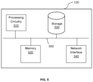
- FIG. 5 is a schematic diagram of a ranging server according to an embodiment.
- the various disclosed embodiments include a method and system for positioning, based on a network of deployed devices incorporating both GNSS and ranging capabilities.
- the ranging is conducted using wireless radio-frequency (RF) based technology.
- the ranging is conducted using Visible Light Communication (VLC) technology.
- the ranging is conducted based on a vision system.
- the ranging is conducted based on a Light detection and ranging (Lidar) system.
- a system and method for global positioning calculation is provided by a user device, using a system that includes deployed stations and a ranging server that combines various ranging techniques and global position information of the stations.
- FIGS. 1 A-C are example block diagrams of a ranging and GNSS positioning system 100 utilized to describe the various disclosed embodiments.
- FIG. 1 A shows a general GNSS positioning system 100
- FIG. 1 B illustrates an example block diagram of Streel Level Stations (SLS)
- FIG. 1 C illustrates an example block diagram of a mobile user device.
- SLS Streel Level Stations
- the GNSS positioning system 100 is composed of multiple Streel Level Stations (SLS), 110 1-n (hereinafter SLS 110 ), a ranging server 120 , and an end user device 130 .
- SLS 110 may have a GNSS receiver 112 ( FIG. 1 B ) and a GNSS antenna 114 ( FIG. 1 B ), respectively, to communicate with satellites 180 and receive satellite signals 182 .
- the SLS 110 is connected to the ranging server 120 using a wireless base-station or hotspot 140 , through a wireless communication link 152 , such as Wi-Fi or cellular 4G Long Term Evolution (LTE) or cellular 5G, and through the wireless mobile operator network 150 , via a mix of wireless, backhaul, and wireline links, 154 and 158 .
- a wireless communication link 152 such as Wi-Fi or cellular 4G Long Term Evolution (LTE) or cellular 5G
- LTE Long Term Evolution
- 5G wireless mobile operator network
- the SLS 110 can be connected to the ranging server 120 via a wireline/landline operator network 160 in connection with communication links 162 and 158 .
- each SLS 110 uses the wireless transceiver 119 and a wireless antenna, or in the wireline alternative, a wireline modem 118 .
- the SLS 110 also has a computing and storage device 111 .
- the SLS 110 further has wireless RF based ranging capabilities using RF ranging transceiver 113 , and RF antenna 115 , such as Ultra-Wide Band (UWB), WiFi ranging, cellular ranging, etc.
- UWB Ultra-Wide Band
- the SLS 110 assists the user devices 130 to conduct ranging and azimuth measurements using vision-based technologies.
- the SLS 110 further includes a digital display 117 . While the ranging and wireless communication elements are described separately here, in some cases a single element may support both wireless communication and ranging capabilities, including UWB, cellular LTE or Fifth Generation (5G) cellular communication.
- 5G Fifth Generation
- the SLSs 110 are static, and while an SLS 110 can be a dedicated device deployed in a certain area, within a modern environment like a city or a highway, there are various already deployed devices that can operate as an SLS 110 , for example: cellular base-stations, information kiosks, smart street-lights, digital signage, and more. These devices are equipped with the required hardware to support the capabilities needed for operation of SLS 110 .
- the location (i.e., the exact global position) of each SLS 110 is known to both the SLS 110 itself and the ranging server 120 . The knowledge about the location can be gathered manually, where surveying teams are dispatched to conduct precise location measurements and configure the result into the GNSS system 100 .
- the location can alternatively be determined autonomously by the GNSS system 100 , either locally at the SLS 110 , or at the ranging server 120 using positioning techniques such as point-positioning, or Precise Point Positioning (PPP).
- PPP Precise Point Positioning
- the ranging server 120 communicates with the network of SLS 110 and with the user device 130 .
- the ranging server 120 is a centralized computing and storage system, which can be located either in a public or private cloud, or in a hybrid cloud solution (i.e., including both public and private clouds), and potentially even become distributed once Mobile Edge Computing (MEC) infrastructure becomes available.
- MEC Mobile Edge Computing
- the user device 130 has wireless communication capabilities using a wireless transceiver 132 and antenna 134 .
- the user device 130 further includes a processor and storage 136 for analyzing and storing data.
- the user device 130 allows for GNSS capabilities to communicate with satellites 180 and receive satellite signals 182 via a GNSS receiver 138 and an antenna 131 .
- the user device 130 additionally uses wireless RF-based components (not shown) to conduct ranging using the ranging transceiver 170 , with one or more SLS 110 , using a ranging transceiver 133 , and antenna 135 .
- the user device 130 includes a camera 137 to measure and estimate ranging and azimuth to the SLS 110 .
- the user device 130 uses embedded VLC capabilities to conduct ranging measurements. This can be conducted using dedicated hardware such as dedicated photodiode for the reception and light-emitting-diode (LED) based transmitter, or using existing hardware such as camera, ambient light sensor, and flashlight.
- the range measurement is conducted using Lidar based scanner.
- the SLSs 110 may periodically transmit a broadcast beacon message to detect, in the case of wireless RF ranging or VLC based ranging, or to display a dedicated image periodically.
- the activation of the SLSs 110 for ranging transmission may be triggered by a specific request sent by the user device 130 , by periodic transmission of the user device 130 , or by the ranging server 120 , based on the GNSS measurements collected from the SLSs 110 .
- the ranging server 120 may determine various parameters collected by SLSs 110 or the user device 130 to determine which of the ranging resources (e.g., SLSs 110 ) are to be activated, and the best satellites 180 to be selected out of the set of received satellites 180 in order to calculate the position of the user device 130 .
- These parameters may include the region in which the SLSs 110 and the user device 130 are located, the time of the day, and the availability of the satellites 180 for ranging.
- the ranging server 120 may then select specific SLSs 110 from a superset of SLSs 110 for ranging activation and compile a list of these specific SLSs 110 . For example, depending on the location where the user device 130 is located, the ranging server will activate only the SLSs 110 closest to the user device 130 in a region for ranging, and depending on the time of day, when certain satellite 180 or groups of satellites 180 distributed in the sky are overhead and available to conduct ranging and communication. The ranging server 120 may then send the compiled list of SLSs 110 to a storage to be saved for later use. Alternatively, the ranging server 120 may send the list to the SLSs 110 to indicate their activation, or to a management server (e.g., a cellular operator network) (not shown) to activate the SLSs 110 .
- a management server e.g., a cellular operator network
- the SLS 110 displays an image
- this image can be displayed for a fairly long period of time (for example 1 second).
- the display 117 may be used for broadcasting purposes, for example, to display a banner.
- the display 117 may be used for advertisement, where the dedicated image is displayed in a manner that a human eye does not notice its appearance. For example, 1/60 Hz or 2/60 Hz which means that in the case of 60 Hz display the image is displayed only 1 or 2 of 60 frames. This means that the digital camera 137 may still be able to detect and process the displayed image.
- the information may be transmitted over the broadcasted message or beacon, or the image displayed may be controlled by the ranging server 120 .
- the user device 130 moves with a user within a region and may calculate its own position.
- the user device 130 includes an embedded wireless transceiver 132 and antenna 134 , and is capable of calculating its own location, in some scenarios (such as in urban environment with low satellite visibility) the user device 130 may utilize the proposed GNSS system 100 to enhance its positioning determination, and reach a solution with better accuracy and reliability.
- FIG. 2 shows a method 200 of managing ranging activation, according to an embodiment.
- the method 200 may be performed by a ranging server 120 over the network.
- a request to activate ranging resources is received.
- the request may come via selection by the user at the user device 130 .
- the request may be received periodically from the user device 130 .
- the ranging server 120 may request for ranging activation by itself, based on the GNSS measurements collected by the SLSs 110 .
- various parameters are determined to determine which of the ranging resources (e.g., SLSs 110 ) are to be activated, and the best satellites 180 to be selected out of the set of received satellites 180 in order to calculate the position of the user device 130 .
- These parameters may include the region in which the SLSs 110 and the user device 130 are located, the time of the day that the request is made, and the availability of the satellites 180 for ranging.
- specific SLSs 110 are selected from a superset of SLSs 110 for ranging activation. For example, depending on the location where the user device 130 makes the ranging activation request, only the specific SLSs 110 closest to the user device 130 is activated for ranging, and depending on the time of day, when certain satellite 180 or groups of satellites 180 distributed in the sky are overhead and available to conduct ranging and communication, certain SLSs 110 may be selected.
- a list of SLSs 110 to be activated for ranging is constructed.
- the list of the selected SLSs 110 is sent to the SLSs 110 to indicate their activation. Alternatively, the list may be stored or sent to a management server (e.g., a cellular operator network) to activate the SLSs 110 .
- a management server e.g., a cellular operator network
- resources for conducting ranging could be conserved and efficiently allocated.
- only the SLSs 110 that are required for ranging with the user device 130 are activated, which saves energy, resources, and cost.
- the users' positioning performance within the region they are located is optimized.
- active SLSs 110 may be deactivated when there are no users in the region, or when conditions changes for the satellites in view such that accurate positioning can only be enabled by GNSS, thus minimizing resource wear and energy use.
- FIG. 3 shows a method 300 of conducting positioning of the GNSS device, according to an embodiment.
- the method may be performed periodically or due to a trigger by the user device 130 .
- a list of SLSs is received. This list can be received in multiple methods. One example is by communication with the ranging server 120 through an Internet protocol like TCP/IP. Another example is retrieving the list of SLSs periodically (e.g., once a week), and store the list in the storage 136 . When the list is needed, it may be retrieved from the compute and storage 136 .
- the received list can also be constructed or filtered based on a coarse location of the user device 130 , based on the ranging capabilities of the user device 130 (that are required to match to the capabilities of the SLS), or a combination of both the coarse location and the ranging capabilities of the user device 130 .
- receiving the list of SLSs may not be necessary, as the SLSs 110 broadcast their availability (e.g., in the case of ranging over cellular networks).
- ranging is conducted with the available SLSs 110 (e.g., the SLSs in the list that are available in its close vicinity).
- the measurement of the range between the two end-points i.e., between the user device 130 and the SLS 110
- the end result is devised at the initiating side (whether at the user device or the SLS). Therefore, if the initiating side is at the SLS 110 then the result is transferred to the user device 130 directly (through the wireless network), or via the ranging server 120 (that may aggregate the results of several SLSs 110 ).
- the user device 130 uses the embedded camera 137 captures the image and estimates the range and azimuth towards the SLS 110 locally.
- the image can present a certain geometric figure (such as a square of predefined size) and in accordance with its capture size, an estimate of the range can be derived.
- the azimuth also can be estimated.
- the type of image i.e., the displayed figures and their dimensions
- the ranging server 120 delivers this information to the user device 130 to detect and process the images displayed by the SLS 110 .
- a wireless base-station 140 may transmit dedicated signals for ranging (such as the ones standardized in LTE). This enables the user device 130 to measure its distance to the base-station 140 .
- a Lidar scanner (not shown) may be used by the user device 130 to scan and analyze its surrounding.
- a three-dimensional (3D) point-cloud is received at the user device 130 .
- the SLS 110 or the ranging server 120 delivers to the user device 130 an image or 3D model of the SLS 110 , which is used by the user device 130 to locate the SLS 110 within the point-cloud. Once the SLS (or several SLSs) 110 is located, the user device extracts the ranging and azimuth (angle) towards the SLS 110 .
- the image and/or 3D model of the SLS 110 may be stored at the user device 130 as part of a SLS “memory bank” that includes the location of all potential SLSs 110 within a certain region.
- This “memory bank” is delivered at when the user device 130 is turned on, periodically (e.g., once a day), or when the user device enters a new geographical region (e.g., a new city).
- the global position of the SLSs 110 in use is received by the user device 130 .
- This information may exist as part of the SLSs list received at S 310 , or received directly from the SLS 110 , over the wireless communication link, or through the ranging server 120 . Additionally, the SLS 110 may publish its own location, and the list of other surrounding SLSs 110 along with their locations.
- the user device may calculate an estimate of its location (the accuracy depends on various parameters).
- additional assisting information from other sources may be received by the user device 130 .
- the GNSS receiver 138 and antenna 131 in the user device 130 receive position-related data from an Inertial Measurement Unit (IMU) or any other sensor or external source, the GNSS receiver 138 can combine the information and calculate the position, as described below.
- IMU Inertial Measurement Unit
- the position of the user device 130 is calculated by the user device 130 based on the ranging measurements and the position of the SLSs 110 . This is done via triangulation techniques, for cases where only ranging is calculated, or via calculation of the range and azimuth impact on the geographic coordinate system (such as longitude and latitude).
- the combination with other information sources can be done by applying joint estimation techniques, or by simple or weighted averaging of all derived positions.
- the user device 130 may then update the ranging server 120 on its position.
- the method 300 described above can also be conducted at the ranging server 120 .
- the ranging results and information about the used SLSs are required to be delivered to the ranging server 120 in one direction, and the calculated positioning result delivered to the user device 130 on the other direction.
- P i , k ⁇ [ t 0 ] ( x r , t 0 - x i , t 0 ) 2 + ( y r , t 0 - y i , t 0 ) 2 + ( z r , t 0 - z i , t 0 ) 2 + c ⁇ d ⁇ ⁇ ⁇ i , t 0 + ⁇ i , t 0 ( 1 )
- P i,k ⁇ i th is ranging source measured range at epoch k taken at t 0 [m]
- ⁇ _r ⁇ circumflex over ( ) ⁇ 0 denotes the receiver coordinates at epoch time t 0 .
- Eq. (3) has the form of a linear form as follows:
- the minimal number of received ranges must exceed the number of parameters needs to be estimated. Therefore, a minimal set of three range measurements is required. However, the larger set the better performance gained. In some cases, the gain added is not equal between measurements and there are also limitations of number of collected ranges due to power consumption, latency etc. In this case a selection policy of the optimal number of range sources along with the specific collection of sources may be generated and provisioned in the central computing center and handed over to the end user.
- a set of GNSS range measurements are combined with time-of-flight ranging (ToF) or other round-trip time measurements (e.g. using UWB transceivers).
- ToF time-of-flight ranging
- UWB transceivers e.g. using UWB transceivers
- n_1 indicates the number of GNSS satellites used while the other ranging measurements sources provide N ⁇ n _1 observable (e.g. UWB, VLC, etc.).
- N the number of GNSS satellites used while the other ranging measurements sources provide N ⁇ n _1 observable (e.g. UWB, VLC, etc.).
- the position estimate proceeds as presented in the WLS framework above presented in Eq. (5).
- Equation (2-6) is one of many potential ways to solve Eq. (1) and it is given as an example to the flow. There are iterative ways, non-linear, numerical analysis methods, and gradient descent, to name a few.
- the combination of two and more range sensors data in a single state vector formulation is not disclosed in the art. Here, some sensors might need calibration procedure in order to better perform in the combined set.
- Some of the calibration procedures that may be applied to the range measurements include: (a) interference reduction, (b) scaling, and (c) timing adjustment.
- FIG. 4 is an example flowchart 400 detailing a position calculation method 400 using GNSS positioning and ranging based a combined model, according to an embodiment.
- raw GNSS measurements are collected from a GNSS receiver.
- range measurements are conducted using technologies other-than with GNSS techniques.
- the raw measurements from both S 410 and S 420 are then transferred via interfaces, and at respective S 412 and S 422 , time epochs of each transceiver are extracted, whether they are collected using GNSS or non-GNSS techniques.
- the collected data is transferred via interfaces to a processing entity (not shown), the two streams of measurements are aligned by time interpolation into single time as if the entire set of measurements was received by single transceiver.
- a GNSS clock bias element may be coupled into the model.
- the unified data structure is sent by an interface to a positioning engine, and at S 450 the position is determined.
- the implementation of the positioning engine and/or the model combining the measurements at S 430 and S 440 may occur on the user device 130 side.
- S 430 and S 440 may be implemented at the ranging server 120 .
- FIG. 5 is an example schematic diagram of a ranging server 120 according to an embodiment.
- the ranging server 120 includes a processing circuitry 510 coupled to a memory 520 , a storage 530 , and a network interface 540 .
- the components of the ranging server 120 may be communicatively connected via a bus 550 .
- the processing circuitry 510 may be realized as one or more hardware logic components and circuits.
- illustrative types of hardware logic components include field programmable gate arrays (FPGAs), application-specific integrated circuits (ASICs), Application-specific standard products (ASSPs), system-on-a-chip systems (SOCs), general-purpose microprocessors, microcontrollers, digital signal processors (DSPs), and the like, or any other hardware logic components that can perform calculations or other manipulations of information.
- the memory 520 may be volatile (e.g., RAM, etc.), non-volatile (e.g., ROM, flash memory, etc.), or a combination thereof.
- computer readable instructions to implement one or more embodiments disclosed herein may be stored in the storage 530 .
- the memory 520 is configured to store software.
- Software shall be construed broadly to mean any type of instructions, whether referred to as software, firmware, middleware, microcode, hardware description language, or otherwise. Instructions may include code (e.g., in source code format, binary code format, executable code format, or any other suitable format of code). The instructions, when executed by the processing circuitry 510 , cause the processing circuitry 510 to perform the various processes described herein.
- the storage 530 may be magnetic storage, optical storage, and the like, and may be realized, for example, as flash memory or other memory technology, CD-ROM, Digital Versatile Disks (DVDs), or any other medium which can be used to store the desired information.
- flash memory or other memory technology
- CD-ROM Compact Discs
- DVDs Digital Versatile Disks
- the network interface 540 allows the ranging server 120 to communicate with various components including the mobile operator network 150 and the wireline operator network 160 for the purpose of, for example, receiving data, sending data, and the like. Further, the network interface 540 allows the ranging server 120 to communicate with the SLSS 110 and the user device 130 for the purpose of collecting ranging and positioning data.
- the various embodiments disclosed herein can be implemented as hardware, firmware, software, or any combination thereof.
- the software is preferably implemented as an application program tangibly embodied on a program storage unit or computer readable medium consisting of parts, or of certain devices and/or a combination of devices.
- the application program may be uploaded to, and executed by, a machine comprising any suitable architecture.
- the machine is implemented on a computer platform having hardware such as one or more central processing units (“CPUs”), a memory, and input/output interfaces.
- CPUs central processing units
- the computer platform may also include an operating system and microinstruction code.
- a non-transitory computer readable medium is any computer readable medium except for a transitory propagating signal.
- any reference to an element herein using a designation such as “first,” “second,” and so forth does not generally limit the quantity or order of those elements. Rather, these designations are generally used herein as a convenient method of distinguishing between two or more elements or instances of an element. Thus, a reference to first and second elements does not mean that only two elements may be employed there or that the first element must precede the second element in some manner. Also, unless stated otherwise, a set of elements comprises one or more elements.
- the phrase “at least one of” followed by a listing of items means that any of the listed items can be utilized individually, or any combination of two or more of the listed items can be utilized. For example, if a system is described as including “at least one of A, B, and C,” the system can include A alone; B alone; C alone; 2 A; 2 B; 2 C; 3 A; A and B in combination; B and C in combination; A and C in combination; A, B, and C in combination; 2 A and C in combination; A, 3 B, and 2 C in combination; and the like.
Landscapes
- Engineering & Computer Science (AREA)
- Radar, Positioning & Navigation (AREA)
- Remote Sensing (AREA)
- Physics & Mathematics (AREA)
- Computer Networks & Wireless Communication (AREA)
- General Physics & Mathematics (AREA)
- Electromagnetism (AREA)
- Position Fixing By Use Of Radio Waves (AREA)
Abstract
Description
where Pi,k−ith is ranging source measured range at epoch k taken at t0 [m]
-
- xr, yr, zr—the receiver coordinates in Earth Centered Earth Fixed system (ECEF) [m]
- xi, yi, zi—the ith ranging source coordinates (ECEF) [m]
- c·dτ—range added due to receiver clock bias (when applicable—e.g. GNSS) [m]
- ∈i—ranging measurement error [m]
αr 0 =[x r ,y r ,z r ]r 0 T (2)
where y is a measurements vector [N×1], H—a linearized model matrix [N×3] and θ the unknown vector [3×1].
{circumflex over (θ)}=(H T WH)−1 ·H T⇒
where W is a diagonal weighting matrix. W is computed to follow an optimization criterion such as estimation minimal variance. In a naïve equal combining case W=I where I is the identity matrix.
Claims (24)
Priority Applications (1)
| Application Number | Priority Date | Filing Date | Title |
|---|---|---|---|
| US16/952,954 US12140683B2 (en) | 2019-11-25 | 2020-11-19 | System and method for combined ranging and GNSS positioning |
Applications Claiming Priority (2)
| Application Number | Priority Date | Filing Date | Title |
|---|---|---|---|
| US201962939701P | 2019-11-25 | 2019-11-25 | |
| US16/952,954 US12140683B2 (en) | 2019-11-25 | 2020-11-19 | System and method for combined ranging and GNSS positioning |
Publications (2)
| Publication Number | Publication Date |
|---|---|
| US20210157017A1 US20210157017A1 (en) | 2021-05-27 |
| US12140683B2 true US12140683B2 (en) | 2024-11-12 |
Family
ID=75971473
Family Applications (1)
| Application Number | Title | Priority Date | Filing Date |
|---|---|---|---|
| US16/952,954 Active 2041-05-11 US12140683B2 (en) | 2019-11-25 | 2020-11-19 | System and method for combined ranging and GNSS positioning |
Country Status (1)
| Country | Link |
|---|---|
| US (1) | US12140683B2 (en) |
Citations (28)
| Publication number | Priority date | Publication date | Assignee | Title |
|---|---|---|---|---|
| US20020033767A1 (en) * | 1997-02-03 | 2002-03-21 | Krasner Norman F. | Method and apparatus for satellite positioning system (SPS) time measurement |
| US6701153B1 (en) * | 2000-07-28 | 2004-03-02 | Lucent Technologies Inc. | Methods and systems for determining the location of mobiles in a UMTS telecommunications system |
| US20040041728A1 (en) * | 2001-07-18 | 2004-03-04 | Bromley Patrick G. | Method and system for processing positioning signals based on predetermined message data segment |
| US20060166671A1 (en) * | 2005-01-21 | 2006-07-27 | Samsung Electronics Co., Ltd. | Handoff mechanism for CDMA wireless network using dynamically scalable traffic channels |
| US20080186135A1 (en) * | 2004-09-03 | 2008-08-07 | Boling Brian M | Mass occupant emergency notification system using satellite radio downlink |
| US20100093377A1 (en) * | 2001-12-27 | 2010-04-15 | Qualcomm Incorporated | Creating And Using Base Station Almanac Information In A Wireless Communication System Having A Position Location Capability |
| US20100117898A1 (en) * | 2007-04-12 | 2010-05-13 | Wigren Torbjoern | Determining positioning of wireless terminal in telecommunications network |
| US20110142099A1 (en) * | 2008-06-02 | 2011-06-16 | Nav On Time | Control device for one or more self-propelled mobile apparatus |
| US20120235812A1 (en) * | 2011-03-18 | 2012-09-20 | Microsoft Corporation | Device location detection |
| US20130023282A1 (en) * | 2011-07-22 | 2013-01-24 | Microsoft Corporation | Location determination based on weighted received signal strengths |
| US20140233624A1 (en) * | 2013-02-19 | 2014-08-21 | Qualcomm Incorporated | Method and apparatus to determine time and distance between transceivers using phase measurements |
| US20150038180A1 (en) * | 2013-07-31 | 2015-02-05 | Qualcomm Incorporated | Paging area reduction based predictive mobility |
| US20150223185A1 (en) * | 2012-08-08 | 2015-08-06 | John Harris | Reactivating Cells to Improve Positioning Accuracy |
| US9197297B2 (en) * | 2000-06-13 | 2015-11-24 | Comcast Cable Communications, Llc | Network communication using diversity |
| US20170214744A1 (en) * | 2015-11-30 | 2017-07-27 | Veniam, Inc. | Systems and methods for adapting a network of moving things, for example including autonomous vehicles, based on user feedback |
| US20180032088A1 (en) * | 2015-03-02 | 2018-02-01 | Izak Jan van Cruyningen | Flight planning for unmanned aerial tower inspection |
| US20180259338A1 (en) * | 2015-11-13 | 2018-09-13 | FUR Belgium BVBA | Sonar sensor fusion and model based virtual and augmented reality systems and methods |
| US20190053191A1 (en) * | 2018-06-26 | 2019-02-14 | Intel IP Corporation | Technologies for predictive alignment of antenna array of a vehicle |
| US20190172008A1 (en) * | 2017-04-03 | 2019-06-06 | Joseph Hage | Redundant wireless electronic motor vehicle chassis monitoring network |
| US10578743B1 (en) * | 2018-12-27 | 2020-03-03 | Intel Corporation | System and method of location determination using multiple location inputs |
| US10813072B1 (en) * | 2014-07-07 | 2020-10-20 | Microstrategy Incorporated | Proximity services |
| US20200408927A1 (en) * | 2019-06-28 | 2020-12-31 | Sony Corporation | Collaborative positioning |
| US10986600B1 (en) * | 2018-12-05 | 2021-04-20 | Nxp Usa, Inc. | Timing synchronization for multi-user (MU) ranging measurements in a wireless local area network (WLAN) |
| US20210325504A1 (en) * | 2018-08-30 | 2021-10-21 | Second Bridge Inc. | Methods for optimization in geolocation using electronic distance measurement equipment |
| US20210396889A1 (en) * | 2018-10-24 | 2021-12-23 | Panasonic Intellectual Property Management Co., Ltd. | Server, satellite positioning system, and satellite positioning method |
| US20220246024A1 (en) * | 2019-05-30 | 2022-08-04 | Signify Holding B.V. | System and methods to provide emergency support using lighting infrastructure |
| US20220346000A1 (en) * | 2019-09-04 | 2022-10-27 | Lg Electronics Inc. | Method and device for measuring location of terminal in wireless communication system |
| US20220373639A1 (en) * | 2019-09-25 | 2022-11-24 | Exacttrak Limited | Asset tracker, method of tracking an asset and security server for locating the asset |
-
2020
- 2020-11-19 US US16/952,954 patent/US12140683B2/en active Active
Patent Citations (29)
| Publication number | Priority date | Publication date | Assignee | Title |
|---|---|---|---|---|
| US20020033767A1 (en) * | 1997-02-03 | 2002-03-21 | Krasner Norman F. | Method and apparatus for satellite positioning system (SPS) time measurement |
| US9197297B2 (en) * | 2000-06-13 | 2015-11-24 | Comcast Cable Communications, Llc | Network communication using diversity |
| US6701153B1 (en) * | 2000-07-28 | 2004-03-02 | Lucent Technologies Inc. | Methods and systems for determining the location of mobiles in a UMTS telecommunications system |
| US20040041728A1 (en) * | 2001-07-18 | 2004-03-04 | Bromley Patrick G. | Method and system for processing positioning signals based on predetermined message data segment |
| US20100093377A1 (en) * | 2001-12-27 | 2010-04-15 | Qualcomm Incorporated | Creating And Using Base Station Almanac Information In A Wireless Communication System Having A Position Location Capability |
| US20080186135A1 (en) * | 2004-09-03 | 2008-08-07 | Boling Brian M | Mass occupant emergency notification system using satellite radio downlink |
| US20060166671A1 (en) * | 2005-01-21 | 2006-07-27 | Samsung Electronics Co., Ltd. | Handoff mechanism for CDMA wireless network using dynamically scalable traffic channels |
| US20100117898A1 (en) * | 2007-04-12 | 2010-05-13 | Wigren Torbjoern | Determining positioning of wireless terminal in telecommunications network |
| US20110142099A1 (en) * | 2008-06-02 | 2011-06-16 | Nav On Time | Control device for one or more self-propelled mobile apparatus |
| US20120235812A1 (en) * | 2011-03-18 | 2012-09-20 | Microsoft Corporation | Device location detection |
| US20130023282A1 (en) * | 2011-07-22 | 2013-01-24 | Microsoft Corporation | Location determination based on weighted received signal strengths |
| US20150223185A1 (en) * | 2012-08-08 | 2015-08-06 | John Harris | Reactivating Cells to Improve Positioning Accuracy |
| US20140233624A1 (en) * | 2013-02-19 | 2014-08-21 | Qualcomm Incorporated | Method and apparatus to determine time and distance between transceivers using phase measurements |
| US20150038180A1 (en) * | 2013-07-31 | 2015-02-05 | Qualcomm Incorporated | Paging area reduction based predictive mobility |
| US10813072B1 (en) * | 2014-07-07 | 2020-10-20 | Microstrategy Incorporated | Proximity services |
| US20180032088A1 (en) * | 2015-03-02 | 2018-02-01 | Izak Jan van Cruyningen | Flight planning for unmanned aerial tower inspection |
| US20180259338A1 (en) * | 2015-11-13 | 2018-09-13 | FUR Belgium BVBA | Sonar sensor fusion and model based virtual and augmented reality systems and methods |
| US20170214744A1 (en) * | 2015-11-30 | 2017-07-27 | Veniam, Inc. | Systems and methods for adapting a network of moving things, for example including autonomous vehicles, based on user feedback |
| US20190172008A1 (en) * | 2017-04-03 | 2019-06-06 | Joseph Hage | Redundant wireless electronic motor vehicle chassis monitoring network |
| US20190053191A1 (en) * | 2018-06-26 | 2019-02-14 | Intel IP Corporation | Technologies for predictive alignment of antenna array of a vehicle |
| US20210325504A1 (en) * | 2018-08-30 | 2021-10-21 | Second Bridge Inc. | Methods for optimization in geolocation using electronic distance measurement equipment |
| US20210396889A1 (en) * | 2018-10-24 | 2021-12-23 | Panasonic Intellectual Property Management Co., Ltd. | Server, satellite positioning system, and satellite positioning method |
| US10986600B1 (en) * | 2018-12-05 | 2021-04-20 | Nxp Usa, Inc. | Timing synchronization for multi-user (MU) ranging measurements in a wireless local area network (WLAN) |
| US10578743B1 (en) * | 2018-12-27 | 2020-03-03 | Intel Corporation | System and method of location determination using multiple location inputs |
| WO2020139497A1 (en) * | 2018-12-27 | 2020-07-02 | Intel Corporation | System and method of location determination using multiple location inputs |
| US20220246024A1 (en) * | 2019-05-30 | 2022-08-04 | Signify Holding B.V. | System and methods to provide emergency support using lighting infrastructure |
| US20200408927A1 (en) * | 2019-06-28 | 2020-12-31 | Sony Corporation | Collaborative positioning |
| US20220346000A1 (en) * | 2019-09-04 | 2022-10-27 | Lg Electronics Inc. | Method and device for measuring location of terminal in wireless communication system |
| US20220373639A1 (en) * | 2019-09-25 | 2022-11-24 | Exacttrak Limited | Asset tracker, method of tracking an asset and security server for locating the asset |
Also Published As
| Publication number | Publication date |
|---|---|
| US20210157017A1 (en) | 2021-05-27 |
Similar Documents
| Publication | Publication Date | Title |
|---|---|---|
| KR101750469B1 (en) | Hybrid photo navigation and mapping | |
| JP5026086B2 (en) | TDOA / GPS hybrid wireless position detection system | |
| EP4337973B1 (en) | Determining position information of mobile devices | |
| US20230221399A1 (en) | Devices, Systems and Methods for Detecting Locations of Wireless Communication Devices | |
| EP2940490B1 (en) | Determining clock-drift using signals of opportunity | |
| TWI557418B (en) | Method and system for computing universal hybrid navigation information for a gnss enabled device | |
| US9587951B1 (en) | Map matching methods and system for tracking and determining improved position of reference assets | |
| JP2018534537A (en) | Method and system for joint global navigation satellite system (GNSS) diagnostics | |
| KR20150054907A (en) | Estimating and predicting structures proximate to a mobile device | |
| JP2016514247A (en) | Ground positioning system calibration | |
| US12554024B2 (en) | Map-aided satellite selection | |
| US20210239849A1 (en) | Providing an accurate location for a gnss device in urban environments | |
| US12235349B2 (en) | Position accuracy using sensor data | |
| US11656362B2 (en) | System and method for providing cyber security for satellite-based navigation systems | |
| Cui et al. | Feasibility analysis of low-cost GNSS receivers for achieving required positioning performance in CAV applications | |
| KR102268380B1 (en) | Method for measuring distance between mobile station using precise position measurement and system and method for measuring distance between golfer and hole cup using the same | |
| US20100094554A1 (en) | Systems and Methods for Accessing Data Over a Short-range Data Link to Enhance the Performance of a Navigational Unit | |
| US12140683B2 (en) | System and method for combined ranging and GNSS positioning | |
| US11914051B2 (en) | System and method for determining accurate positions of stationary global navigation satellite system sensors | |
| US11500110B2 (en) | Localization using bearing from environmental features | |
| Alam | Vehicular positioning enhancement using DSRC | |
| Huang et al. | Roadside GNSS Aided Multi-Sensor Integrated System for Vehicle Positioning in Urban Areas | |
| Kawahara | Ground-Based and Space-Based Positioning | |
| Sbeity | CY Cergy Paris Université | |
| Salim | Positional Accuracy of Mobile Phones Under Static and Dynamic Conditions |
Legal Events
| Date | Code | Title | Description |
|---|---|---|---|
| AS | Assignment |
Owner name: TUPAIA LTD., ISRAEL Free format text: ASSIGNMENT OF ASSIGNORS INTEREST;ASSIGNORS:LAVI, NADAV;SCHEIM, KOBI;REEL/FRAME:054422/0777 Effective date: 20201119 |
|
| FEPP | Fee payment procedure |
Free format text: ENTITY STATUS SET TO UNDISCOUNTED (ORIGINAL EVENT CODE: BIG.); ENTITY STATUS OF PATENT OWNER: SMALL ENTITY |
|
| FEPP | Fee payment procedure |
Free format text: ENTITY STATUS SET TO SMALL (ORIGINAL EVENT CODE: SMAL); ENTITY STATUS OF PATENT OWNER: SMALL ENTITY |
|
| STPP | Information on status: patent application and granting procedure in general |
Free format text: APPLICATION DISPATCHED FROM PREEXAM, NOT YET DOCKETED |
|
| STPP | Information on status: patent application and granting procedure in general |
Free format text: DOCKETED NEW CASE - READY FOR EXAMINATION |
|
| STPP | Information on status: patent application and granting procedure in general |
Free format text: NON FINAL ACTION MAILED |
|
| STPP | Information on status: patent application and granting procedure in general |
Free format text: RESPONSE TO NON-FINAL OFFICE ACTION ENTERED AND FORWARDED TO EXAMINER |
|
| STPP | Information on status: patent application and granting procedure in general |
Free format text: FINAL REJECTION MAILED |
|
| STPP | Information on status: patent application and granting procedure in general |
Free format text: DOCKETED NEW CASE - READY FOR EXAMINATION |
|
| STPP | Information on status: patent application and granting procedure in general |
Free format text: NON FINAL ACTION MAILED |
|
| STPP | Information on status: patent application and granting procedure in general |
Free format text: RESPONSE TO NON-FINAL OFFICE ACTION ENTERED AND FORWARDED TO EXAMINER |
|
| STPP | Information on status: patent application and granting procedure in general |
Free format text: FINAL REJECTION MAILED |
|
| STPP | Information on status: patent application and granting procedure in general |
Free format text: NOTICE OF ALLOWANCE MAILED -- APPLICATION RECEIVED IN OFFICE OF PUBLICATIONS |
|
| ZAAB | Notice of allowance mailed |
Free format text: ORIGINAL CODE: MN/=. |
|
| STPP | Information on status: patent application and granting procedure in general |
Free format text: PUBLICATIONS -- ISSUE FEE PAYMENT VERIFIED |
|
| STCF | Information on status: patent grant |
Free format text: PATENTED CASE |