US12140023B2 - Systems and methods for adaptive telemetry reception - Google Patents
Systems and methods for adaptive telemetry reception Download PDFInfo
- Publication number
- US12140023B2 US12140023B2 US18/162,527 US202318162527A US12140023B2 US 12140023 B2 US12140023 B2 US 12140023B2 US 202318162527 A US202318162527 A US 202318162527A US 12140023 B2 US12140023 B2 US 12140023B2
- Authority
- US
- United States
- Prior art keywords
- data
- decoding
- header
- transducers
- decoded
- Prior art date
- Legal status (The legal status is an assumption and is not a legal conclusion. Google has not performed a legal analysis and makes no representation as to the accuracy of the status listed.)
- Active
Links
- 238000000034 method Methods 0.000 title claims abstract description 236
- 230000003044 adaptive effect Effects 0.000 title description 9
- 238000005553 drilling Methods 0.000 claims abstract description 77
- 238000012545 processing Methods 0.000 claims description 27
- 208000019300 CLIPPERS Diseases 0.000 claims description 11
- 208000021930 chronic lymphocytic inflammation with pontine perivascular enhancement responsive to steroids Diseases 0.000 claims description 11
- 238000012935 Averaging Methods 0.000 claims description 9
- 238000001514 detection method Methods 0.000 claims description 5
- 230000000875 corresponding effect Effects 0.000 description 62
- 239000012530 fluid Substances 0.000 description 34
- 239000004020 conductor Substances 0.000 description 32
- 230000008569 process Effects 0.000 description 29
- 238000005259 measurement Methods 0.000 description 21
- 238000013499 data model Methods 0.000 description 15
- 230000001143 conditioned effect Effects 0.000 description 11
- 238000010586 diagram Methods 0.000 description 11
- 230000008859 change Effects 0.000 description 10
- 230000002829 reductive effect Effects 0.000 description 9
- 238000005516 engineering process Methods 0.000 description 8
- 238000013473 artificial intelligence Methods 0.000 description 7
- 238000012937 correction Methods 0.000 description 7
- 238000001914 filtration Methods 0.000 description 7
- RUZYUOTYCVRMRZ-UHFFFAOYSA-N doxazosin Chemical compound C1OC2=CC=CC=C2OC1C(=O)N(CC1)CCN1C1=NC(N)=C(C=C(C(OC)=C2)OC)C2=N1 RUZYUOTYCVRMRZ-UHFFFAOYSA-N 0.000 description 6
- 230000006870 function Effects 0.000 description 6
- 238000003708 edge detection Methods 0.000 description 5
- 238000001228 spectrum Methods 0.000 description 5
- 238000004891 communication Methods 0.000 description 4
- 238000005520 cutting process Methods 0.000 description 4
- 238000011143 downstream manufacturing Methods 0.000 description 4
- 230000000007 visual effect Effects 0.000 description 4
- 238000003491 array Methods 0.000 description 3
- 238000013500 data storage Methods 0.000 description 3
- 230000000670 limiting effect Effects 0.000 description 3
- 230000001360 synchronised effect Effects 0.000 description 3
- 241000854350 Enicospilus group Species 0.000 description 2
- 238000007792 addition Methods 0.000 description 2
- 238000004458 analytical method Methods 0.000 description 2
- 230000008901 benefit Effects 0.000 description 2
- 230000015572 biosynthetic process Effects 0.000 description 2
- 230000008878 coupling Effects 0.000 description 2
- 238000010168 coupling process Methods 0.000 description 2
- 238000005859 coupling reaction Methods 0.000 description 2
- 230000001186 cumulative effect Effects 0.000 description 2
- 230000003247 decreasing effect Effects 0.000 description 2
- 238000005755 formation reaction Methods 0.000 description 2
- 230000005484 gravity Effects 0.000 description 2
- 238000010801 machine learning Methods 0.000 description 2
- 238000012986 modification Methods 0.000 description 2
- 230000004048 modification Effects 0.000 description 2
- 238000001208 nuclear magnetic resonance pulse sequence Methods 0.000 description 2
- 238000005457 optimization Methods 0.000 description 2
- 238000012706 support-vector machine Methods 0.000 description 2
- 241000295146 Gallionellaceae Species 0.000 description 1
- 229910000831 Steel Inorganic materials 0.000 description 1
- 230000004075 alteration Effects 0.000 description 1
- 230000002238 attenuated effect Effects 0.000 description 1
- 230000009286 beneficial effect Effects 0.000 description 1
- 230000005540 biological transmission Effects 0.000 description 1
- 238000009530 blood pressure measurement Methods 0.000 description 1
- 230000003750 conditioning effect Effects 0.000 description 1
- 230000001276 controlling effect Effects 0.000 description 1
- 230000002596 correlated effect Effects 0.000 description 1
- 125000004122 cyclic group Chemical group 0.000 description 1
- 238000003066 decision tree Methods 0.000 description 1
- 239000006185 dispersion Substances 0.000 description 1
- 238000002592 echocardiography Methods 0.000 description 1
- 230000003628 erosive effect Effects 0.000 description 1
- 239000000284 extract Substances 0.000 description 1
- 230000008676 import Effects 0.000 description 1
- 238000012417 linear regression Methods 0.000 description 1
- 238000007477 logistic regression Methods 0.000 description 1
- 238000013507 mapping Methods 0.000 description 1
- 239000000203 mixture Substances 0.000 description 1
- 238000003062 neural network model Methods 0.000 description 1
- 230000003287 optical effect Effects 0.000 description 1
- 230000000737 periodic effect Effects 0.000 description 1
- 239000003348 petrochemical agent Substances 0.000 description 1
- 230000010363 phase shift Effects 0.000 description 1
- 229920000747 poly(lactic acid) Polymers 0.000 description 1
- 230000001902 propagating effect Effects 0.000 description 1
- 238000013139 quantization Methods 0.000 description 1
- 238000007637 random forest analysis Methods 0.000 description 1
- 230000009467 reduction Effects 0.000 description 1
- 238000012552 review Methods 0.000 description 1
- 238000005070 sampling Methods 0.000 description 1
- 239000004065 semiconductor Substances 0.000 description 1
- 238000000926 separation method Methods 0.000 description 1
- 239000010959 steel Substances 0.000 description 1
- 238000012360 testing method Methods 0.000 description 1
- 230000001960 triggered effect Effects 0.000 description 1
Images


Classifications
-
- E—FIXED CONSTRUCTIONS
- E21—EARTH OR ROCK DRILLING; MINING
- E21B—EARTH OR ROCK DRILLING; OBTAINING OIL, GAS, WATER, SOLUBLE OR MELTABLE MATERIALS OR A SLURRY OF MINERALS FROM WELLS
- E21B47/00—Survey of boreholes or wells
- E21B47/12—Means for transmitting measuring-signals or control signals from the well to the surface, or from the surface to the well, e.g. for logging while drilling
- E21B47/14—Means for transmitting measuring-signals or control signals from the well to the surface, or from the surface to the well, e.g. for logging while drilling using acoustic waves
- E21B47/18—Means for transmitting measuring-signals or control signals from the well to the surface, or from the surface to the well, e.g. for logging while drilling using acoustic waves through the well fluid, e.g. mud pressure pulse telemetry
-
- E—FIXED CONSTRUCTIONS
- E21—EARTH OR ROCK DRILLING; MINING
- E21B—EARTH OR ROCK DRILLING; OBTAINING OIL, GAS, WATER, SOLUBLE OR MELTABLE MATERIALS OR A SLURRY OF MINERALS FROM WELLS
- E21B2200/00—Special features related to earth drilling for obtaining oil, gas or water
- E21B2200/20—Computer models or simulations, e.g. for reservoirs under production, drill bits
Definitions
- This invention relates to systems and methods for downhole telemetry.
- Example embodiments provide adaptive systems and methods for receiving downhole mud pulse telemetry data.
- Subsurface drilling has application, for example, in recovering petrochemicals from subsurface reservoirs.
- a rotating drill bit at the end of a drill string cuts a borehole.
- the drill bit may be rotated by turning the entire drill string and/or using a downhole motor such as a mud motor.
- Cuttings released by the drilling operation are generally removed from the borehole by flowing drilling fluid through the drill string.
- the drilling fluid flows back to the surface in an annular region of the borehole surrounding the drill string.
- Subsurface drilling may be used to make boreholes that are very deep (e.g. thousands of meters).
- Casing typically takes the form of a steel pipe that surrounds the borehole and extends to a desired depth. Casing is used among other things to prevent fluids from entering or leaving the borehole and to preserve the integrity of the borehole. Casing may extend to very significant depths in the borehole.
- Such data communication may, for example, be used to transmit measurements from downhole sensors.
- the measurements may, for example, include one or more of: measurements of downhole conditions (e.g. temperature, pressure and/or vibration levels), well logging data (e.g. neutron, gamma, magnetic and/or resistivity measurements of formations surrounding the borehole), steering information such as direction (e.g. azimuth) and inclination of a part of the drill string (e.g. the downhole equipment), and/or information regarding the status of items of downhole equipment.
- This information may be used for a wide variety of purposes including controlling drilling operations, scientific inquiry, mapping downhole formations, etc.
- MWD measurement while drilling
- Various types of directional drilling systems are used. To control these systems from the surface it is necessary to have information regarding the orientation of the drill bit.
- a device commonly known as a MWD tool can be included in the bottom hole assembly (BHA).
- the MWD tool provides the directional driller with information such as the orientation of the MWD tool and provides periodic measurements of the direction and inclination of the MWD tool in the wellbore, azimuth, inclination, total magnetic field, total gravitational field, dip, gravity tool face, magnetic tool face, raw gravitation readings, raw magnetic readings, etc.
- the MWD tool encodes this information into a binary data stream that is transmitted to a surface computer that decodes the data stream and presents the information to the directional driller on surface or in a remote location via a suitable data link.
- MP telemetry transmits data by generating pressure pulses that propagate through drilling fluid in the wellbore. The data is encoded in the pressure pulses. MP telemetry may be used to transmit data over long distances.
- mud pulses may be detected by positioning a pressure transducer uphole (e.g. at or close to the surface).
- the pressure transducer senses pressure of the drilling fluid (which includes in itself MP pressure pulses propagating through the drilling fluid) and converts the sensed pulses into an electrical signal that can be processed to retrieve digital information encoded in the MP pressure pulses.
- a problem is that the MP pressure pulses are small relative to the overall pressure of the drilling fluid.
- Other components of the pressure measurement such as ambient pressure and noise (e.g. pump noise, noise from a draw works drum, noise from one or more agitators, etc.) can make it hard to detect the MP pressure pulses.
- MP pressure pulses tend to be attenuated and distorted as they propagate uphole due to factors such as erosion, pressure drop across the borehole, etc.
- the noise picked up by the pressure transducer can change as equipment such as pumps are turned on and off, as drilling conditions change (e.g. depth, rotating vs. sliding modes, stand pipe pressure, etc.), etc.
- the combination of these factors makes reliable detection of MP pressure pulses difficult, especially where the MP pressure pulses originate from deep in the wellbore.
- This invention has a number of aspects. These aspects include without limitation:
- One aspect of the invention provides a method for receiving downhole telemetry data from a drilling operation.
- the method may comprise transmitting data from a downhole location by mud pulse telemetry.
- the method may also comprise receiving the transmitted mud pulse telemetry data at a plurality of transducers. Each of the transducers may be positioned at a different location of the drilling operation.
- the method may also comprise processing the received data from the plurality of transducers to decode the transmitted data.
- the method may also comprise selecting which one of the decoded data items most likely corresponds to the transmitted mud pulse telemetry data.
- processing the received data from the plurality of transducers comprises decoding the received data with a plurality of decoding chains.
- the plurality of decoding chains comprises at least one decoding chain for a corresponding one of each of the plurality of transducers.
- the plurality of decoding chains comprises at least one set of plurality decoding chains corresponding to at least one of the plurality of transducers.
- the decoding chains each comprise at least one filter.
- the at least one filter comprises a low pass filter.
- the at least one filter comprises a high pass filter.
- the received data is filtered by a pump noise filter prior to being processed by the plurality of decoding chains.
- the pump noise filter is configured to supress pump noise from the received data.
- the received data from each of the plurality of transducers is filtered by a different pump noise filter.
- the received data from each of the plurality of transducers is autonomously filtered by a different pump noise filter.
- settings of the pump noise filter are varied as pump noise varies.
- settings of the pump noise filter are autonomously varied as pump noise varies.
- the decoding chains each further comprise a clipper configured to clip data relative to a threshold value.
- the clippers are configured to clip data which falls below the threshold value.
- selecting which one of the decoded data items most likely corresponds to the transmitted mud pulse telemetry data comprises selecting an output of one of the decoding chains which is the most likely to be correct.
- the output which is the most likely to be correct is determined by comparing confidence of a plurality of decoded data items.
- confidence of a decoded data item is based at least partially on a confidence value that a header corresponding to the decoded data item is correctly identified as a header.
- detection of the header is based at least partially on a comparison of a suspected header to a header model.
- the header model is varied as header values are correctly decoded.
- varying the header model comprises averaging a plurality of correct header values together.
- the method comprises varying at least one performance parameter of the plurality of decoding chains to improve the likelihood that at least one decoding chain will correctly decode the received data.
- varying at least one performance parameter of the plurality of decoding chains comprises varying filter settings of at least one of the plurality of decoding chains.
- filter settings of the at least one of the plurality of decoding chains are varied autonomously.
- the method comprises adding or removing decoding chains from the plurality of decoding chains.
- the decoding chains are added or removed from the plurality of decoding chains autonomously.
- the system may comprise a downhole mud pulse (MP) telemetry transmitter configured to transmit data uphole.
- the system may also comprise a plurality of transducers configured to sense drilling fluid pressure changes corresponding to transmitted MP telemetry data.
- the system may also comprise at least one controller configured to perform any method described herein to decode received MP telemetry data.
- Another aspect of the invention provides a method for identifying a sequence of pulses representing a header of a mud pulse (MP) telemetry data message.
- the method may comprise measuring with a transducer changes in pressure of a drilling fluid. At least some of the measured changes in pressure may correspond to encoded MP telemetry data.
- the method may also comprise comparing a window of measurements from the transducer against a template representing the header to determine a correlation value representing how similar the window of measurements is to the template.
- the method may also comprise identifying the window of measurements as comprising the header by comparing the correlation value against a threshold value.
- the method may also comprise dynamically varying the template as windows of measurements comprising the header are identified.
- the window of measurements is identified as comprising the header if the correlation value is greater than or equal to the threshold value.
- dynamically varying the template comprises averaging the template values with measurement values of the measurement windows identified as comprising the header.
- the averaging comprises a weighted average.
- the template initially comprises a sequence of expected pressure pulses.
- Another aspect of the invention provides a method for detecting mud pulse (MP) telemetry data.
- the method may comprise measuring with a transducer changes in pressure of a drilling fluid. At least some of the measured changes in pressure may correspond to encoded MP telemetry data.
- the method may also comprise determining a prototypical shape for the measured changes in pressure corresponding to encoded MP telemetry data.
- the method may also comprise comparing the measured changes in pressure against the prototypical shape to detect encoded MP telemetry data.
- determining the prototypical shape comprises: comparing previously measured changes in pressure that corresponded to encoded MP telemetry data; and determining a shape of the previously measured changes in pressure that has the highest rate of occurrence.
- the method comprises selecting the shape of the previously measured changes in pressure that has the highest rate of occurrence as the prototypical shape for the measured changes in pressure corresponding to encoded MP telemetry data.
- the method comprises comparing a measured change in pressure against the prototypical shape to determine a likelihood of the measured change in pressure corresponding to encoded MP telemetry data.
- the method comprises sorting measured changes in pressure.
- the measured changes in pressure are sorted based on energy levels or amplitudes of the measured changes in pressure.
- the method comprises selecting ones of the sorted measured changes in pressure which have the highest likelihood of corresponding to encoded MP telemetry data for comparison against the prototypical shape.
- the measured changes in pressure having the highest energy levels or amplitudes are selected as having the highest likelihood of corresponding to encoded MP telemetry data.
- the method comprises concatenating at least two measured changes in pressure together.
- the method comprises determining a quality of the measured changes in pressure.
- the quality of the measured changes in pressure is at least partially determined based on the comparison of the measured changes in pressure against the prototypical shape.
- the method comprises updating the prototypical shape based on currently detected MP telemetry data.
- the measured changes are filtered by a pump noise filter.
- the pump noise filter may be configured to supress pump noise.
- the method comprises varying settings of the pump noise filter as pump noise varies.
- settings of the pump noise filter are autonomously varied as pump noise varies.
- the method comprises filtering the measured changes with a plurality of pump noise filters.
- Each of the pump noise filters may be configured to supress pump noise.
- the method comprises determining a prototypical shape for the measured changes in pressure corresponding to encoded MP telemetry data for each pump noise filter of the plurality of pump noise filters.
- FIG. 1 is a schematic illustration of a drilling operation according to an example embodiment of the invention.
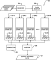
- FIG. 2 is a block diagram of an architecture of a decoding system according to an example embodiment of the invention.
- FIG. 3 is a block diagram of an architecture of a decoding chain set according to an example embodiment of the invention.
- FIGS. 3 A- 3 D are flow charts of methods according to example embodiments of the invention.
- FIG. 4 is a block diagram of a method of removing pump noise from a sensed data signal according to an example embodiment of the invention.
- FIG. 5 A is a graphical illustration of an example sensed data signal.
- FIG. 5 B is a graphical illustration of a frequency spectrum of the sensed data signal of FIG. 5 A .
- FIGS. 6 - 10 are flow charts showing decoding methods according to example embodiments of the invention.
- FIG. 1 is a schematic illustration of an example drilling system 10 .
- Drilling system 10 comprises a drill string 12 and derrick 13 .
- Drill string 12 has a cutting and/or drilling tool 15 (e.g. a drill bit) coupled to an end of drill string 12 .
- Drilling fluid (typically called “mud”) may be delivered through a bore of drill string 12 to cutting and/or drilling tool 15 during a drilling operation. The drilling fluid is circulated back to the surface in an annulus surrounding drill string 12 .
- drilling fluid is circulated from tank 16 A (or a drilling mud pit as may be known in the art) through pipeline 16 B by pump 16 C to a bore of drill string 12 .
- Drilling fluid may be collected from the annulus surrounding drill string 12 and returned to tank 16 A via a pipeline 16 D thereby forming a closed loop fluid path.
- the collected drilling fluid passes through a drilling cuttings separator (not shown) prior to being returned to tank 16 A.
- Downhole parameters of the drilling operation may be measured and communicated uphole using a telemetry method such as mud pulse telemetry.
- MP telemetry data data that is to be communicated
- the data may, for example, be encoded by a scheme which represents digital values by altering the timing between mud pulses and/or the intensities of mud pulses and/or the types of mud pulses (e.g. positive pressure, negative pressure, “siren” continuous wave signals, etc.).
- a scheme which represents digital values by altering the timing between mud pulses and/or the intensities of mud pulses and/or the types of mud pulses (e.g. positive pressure, negative pressure, “siren” continuous wave signals, etc.).
- Many different encoding schemes are possible.
- MP telemetry data may, for example, comprise a header syncing the data that is being transmitted, the data value(s) being transmitted, one or more error checking values (e.g. a check bit), etc.
- the pressure pulses are sensed at an uphole location and decoded to receive the transmitted data.
- the present technology includes systems which include:
- Drilling system 10 may comprise a plurality of transducers 14 (e.g. transducers 14 - 1 , 14 - 2 , 14 - 3 , 14 - 4 ) to receive transmitted mud pulse data (i.e. pressure and/or acoustic sensors which sense changes in pressure in the drilling fluid).
- the plurality of transducers 14 may, for example, comprise a plurality of pressure transducers.
- the mud pulse data signal and any noise present in the signal will vary (e.g. in amplitude, frequency spectrum, etc.) as a function of position of transducer 14 relative to drilling system 10 .
- Transducers 14 may be positioned along the drilling fluid path (e.g. along pipelines 16 B or 16 D) at different locations of drilling system 10 . For example, transducers 14 may be positioned:
- drilling system 10 may have any number of transducers 14 .
- drilling system 10 comprises a plurality of transducers 14 .
- Different transducers 14 may be of the same or different types.
- transducers 14 may be selected from: absolute pressure transducers; relative pressure transducers; and combinations of relative and absolute pressure transducers.
- Transducers 14 may interface to drilling system 10 (e.g. pipelines 16 B or 16 D) in any of a wide range of ways.
- transducers 14 may comprise one or more strap transducers, one or more in-line transducers, or combinations of strap transducers and in-line transducers.
- a data decoding system 20 is connected to receive and process output signals from transducers 14 . At different times during a drilling operation different ones of transducers 14 may be less affected by noise, have higher quality, and/or have more faithful reception of mud pulses that encode MP telemetry data than other transducers 14 .
- System 20 may be configured to select output signals from specific one(s) of transducers 14 that will be processed to recover data that has been transmitted by MP telemetry.
- System 20 may be configured to select specific processing parameters that will be used to process the output signals at least from the selected transducer(s) 14 to decode the MP telemetry data. Each of these selections may be varied dynamically to obtain high reliability decoded data values from transmitted data. For example, as a drilling operation proceeds, different sets of one or more transducers 14 may be selected for receiving the MP telemetry signals and different processing and/or filtering may be applied to the output signals from the selected transducer(s) 14 .
- system 20 comprises one or more trained artificial intelligence models which are configured to select transducer(s) 14 and/or processing and/or filtering to be applied to the output signals of at least the selected transducer(s) 14 for recovering the MP telemetry data.
- FIG. 2 is a block diagram showing an example architecture of decoding system 20 .
- Receiver 21 receives output signals from transducers 14 .
- receiver 21 comprises one or more analog to digital converters, etc. which convert sensed analog signals from transducers 14 to digital signals.
- transducers 14 produce digital signals themselves.
- Receiver 21 may additionally include signal amplifying and/or conditioning electronics (e.g. low pass filters, high pass filters, etc.).
- Flow monitor 22 monitors flow of the drilling fluid.
- MP telemetry data generally requires fluid flow in the drill string to generate the pulses that encode MP telemetry data. Based on the monitored flow, decoding of data may be started or stopped.
- flow monitor 22 may enable processing to detect/decode MP telemetry data upon detecting fluid flow (i.e. fluid flow is ON) and may disable processing to detect/decode MP telemetry data upon detecting no fluid flow (i.e. fluid flow is OFF).
- output signals from at least the selected transducers are delivered from receiver 21 to parts of system 20 that perform downstream processing by way of flow monitor 22 .
- flow monitor 22 may pass or not pass the output signals for downstream processing based on the monitored flow.
- receiver 21 directly passes the sensed data for downstream processing.
- flow monitor 22 generates signals that enable and disable downstream processing based on the detected flow.
- Decoding system 20 also comprises plural sets of decoding chains 24 - 1 , 24 - 2 , . . . , 24 -N (each a “decoding chain set 24 ”, generally and collectively “decoding chain sets 24 ”).
- Decoding chain sets 24 receive the output signals from the selected transducer(s) 14 and process these output signals to decode and output the MP telemetry data.
- Each decoding chain set 24 comprises at least one and preferably more than one decoding chain 30 as described elsewhere herein.
- decoding chain sets 24 may process output signals from different transducers 14 in parallel.
- decoding system 20 comprises at least one decoding chain set 24 for each transducer 14 .
- decoding system 20 does not comprise more than one decoding chain set 24 for a particular transducer 14 .
- decoded data from a particular chain set 24 is determined to be bad (e.g. low confidence, inaccurate decoded data, etc.) the particular decoding chain set 24 may be removed from decoding system 20 or ignored.
- decoding system 20 comprises 10 or fewer decoding chain sets 24 . In some embodiments decoding system 20 comprises 8 decoding chain sets 24 . In some embodiments decoding system 20 comprises one chain set 24 for each transducer 14 .
- decoding chain sets 24 may be implemented at least in part by digital processing by one or more data processors such as one or more digital signal processors (DSPs) and/or one or more microprocessors, etc. In some embodiments decoding chain sets 24 may be implemented at least in part by digital processing by one or more configurable logic devices such as field programmable gate arrays (FPGAs).
- DSPs digital signal processors
- FPGAs field programmable gate arrays
- decoding chains and/or decoding chain sets 24 may be added to or removed from decoding system 20 dynamically. For example, additional decoding chain sets 24 may be dynamically added to improve quality of the decoding, etc. Decoding chain sets 24 may, for example, be removed to reduce processing time for the output signals of transducers 14 , eliminate redundancy, reduce required computational power, etc.
- a decoding chain set or decoding chain may be removed from decoding system 20 by one or more of: putting the decoding chain or decoding chain set in a standby mode, ignoring output from the decoding chain or decoding chain set, disconnecting an input signal from the decoding chain or decoding chain set, not powering one or more hardware components, where present, of the decoding chain or decoding chain set, and/or deleting or idling one or more components of the decoding chain or decoding chain set that is implemented in software (e.g. using digital filters/digital processing) under software control.
- a decoding chain set or decoding chain may be added to decoding system 20 by the opposite of these steps.
- each decoding chain set 24 may comprise a plurality of individual decoding chains 30 (e.g. 30 - 1 , 30 - 2 , 30 - 3 , . . . , 30 -X).
- a decoding chain set 24 initially comprises three or four decoding chains 30 .
- an operator may add additional decoding chains 30 to a decoding chain set 24 .
- a decoding chain set 24 comprises 10 or fewer decoding chains 30 .
- a decoding chain set 24 comprises 8 or fewer decoding chains 30 .
- conductor 28 (described elsewhere herein) dynamically varies the number of decoding chains 30 in a decoding chain set 24 .
- Each decoding chain 30 receives a transducer output signal from a transducer 14 or from a pump noise filter 35 .
- Decoding chain 30 processes the output signal to decode any MP telemetry data present in the output signal.
- decoding chain 30 conditions the transducer output signal prior to attempting to decode any MP telemetry data that may be present in the transducer output signal.
- Different decoding chain sets 24 may include the same or different numbers of decoding chains 30 .
- Each decoding chain 30 attempts to decode transducer output signals that have been allocated to the corresponding decoding chain set 24 .
- Different decoding chains 30 have different performance parameters (e.g. different filter settings, different filter configurations, different decoder settings, etc.).
- each decoding chain 30 comprises a low pass filter 31 and a high pass filter 32 which filter a transducer output signal received from a transducer 14 or pump noise filter 35 .
- the cutoff frequency of low pass filter 31 may, for example, be higher than the cutoff frequency of high pass filter 32 .
- Low pass filter 31 may remove high frequency noise that may be present in the transducer output signal.
- low pass filter 31 has a cutoff frequency in the range from about 2 Hz to about 12 Hz.
- low pass filter 31 comprises a moving average filter.
- low pass filter 31 comprises a multi-stage filter (e.g. two to four stages).
- High pass filter 32 may remove a steady state ambient pressure from the transducer output signal.
- high pass filter 32 has a cutoff frequency in the range from about 0.5 Hz to about 1.5 Hz. In some embodiments high pass filter 32 comprises a moving average filter. In some embodiments high pass filter 32 comprises a multi-stage filter (e.g. two to four stages).
- a difference between the conditioned data from low pass filter 31 and high pass filter 32 may be determined prior to being clipped by clipper 33 . Subtracting the data produces a single data signal from which residual noise and steady state ambient pressure are at least partially eliminated.
- a bandpass filter is used in place of both low pass filter 31 and high pass filter 32 .
- the way in which the transducer output data is filtered can affect the likelihood that MP telemetry data can be reliably decoded. At different times, different filtering may yield the best results.
- Providing plural decoding chains 30 which include different filter combinations for decoding data from the transducer output signals of a transducer 14 increases the likelihood that MP telemetry data will be successfully and reliably decoded by at least one of decoding chains 30 .
- Clipper 33 removes any negative pressure values from the filtered transducer output signals (i.e. only positive pressure values remain). For example, clipper 33 may be configured to set any negative amplitude values to 0. Clipper 33 is optional and may have significant benefit depending on the nature of the transmitted MP telemetry data. Clipper 33 may, for example, be beneficial where MP telemetry data is encoded in positive pressure pulses.
- transducer output signals may be filtered by a pump noise filter 35 (not necessary in all embodiments).
- Pump noise filters 35 may be configured to suppress pump noise in the transducer output signals.
- pump noise filter 35 is configured to identify and lock onto a frequency corresponding to pump noise which is present in the sensed data. Pump noise filter 35 preferably maintains a frequency lock on the pump noise even if the frequency drifts over time. Based on the identified and locked onto frequency, pump noise filter 35 may comprise one or more notch filters to remove pump noise from the transducer output signals. In some embodiments the frequency lock of pump noise filter 35 is accurate to within at least 10E-4 Hz. Preferably, the frequency lock of pump noise filter 35 is accurate to within at least 10E-5 Hz.
- pump noise filter 35 may comprise an artificial intelligence model which is trained to lock onto the frequency corresponding to pump noise.
- pump noise filter 35 comprises a series of notch filters. Each notch filter may be designed to remove a specific frequency from the transducer output signals. Each notch filter may be separately tunable. Decoder 34 decodes processed transducer output signals (e.g. filtered and/or clipped transducer output signals) to extract MP telemetry data.
- MP telemetry data is encoded in sequences of pressure pulses. There are a wide range of protocols for encoding data in pressure pulses. In general, data is encoded by creating patterns in the relative timing and/or amplitudes of a series of pulses. For example, protocols such as phase shift keying (PSK) or quadrature amplitude modulation (QAM) may be used to encode MP telemetry data.
- PSK phase shift keying
- QAM quadrature amplitude modulation
- the likelihood of an output from a single decoding chain 30 being correct may be self-evaluated at least partially by decoder 34 based on one or more of the following:
- system 10 includes a functional unit or component which, among other functions, analyzes and determines which output of which decoding chain 30 to use as the decoded data.
- This functional unit or component is referred to as “auditor 26 ” herein.
- Auditor 26 receives processed data from individual decoding chains 30 of decoding chain sets 24 .
- Auditor 26 analyzes the decoded data from decoding chains 30 and determines which output from which decoding chain 30 to output as decoded MP telemetry data 27 .
- Which data to output as decoded MP telemetry data 27 is determined by comparing the data output by each of decoding chains 30 and determining which output of which decoding chain 30 is most likely to be correct.
- a user may select which output from which decoding chain 30 to output as decoded MP telemetry data 27 .
- Auditor 26 may, for example, comprise an artificial intelligence model which is configured to compare outputs of the different decoding chains 30 and determine which output is most likely to be correct. For example, auditor 26 may compare (e.g. with a comparator) outputs of the different chain sets 24 and/or outputs of individual decoding chains 30 and select the most frequently occurring output value (e.g. based on how many instances of that output value occur compared to the other output values) as the output value that is the most likely to be correct. If, for example, there are two decoding chain sets 24 with four decoding chains 30 each (e.g.
- Auditor 26 may ensure that MP telemetry data that is output from each decoding chain 30 within a decoding chain set 24 is time synchronized.
- auditor 26 conditions the output decoded data from decoding chains 30 for the data to be time synchronized.
- MP telemetry data may be detected at different transducers 14 at different times due to different propagation times from the source of the MP telemetry data to the different transducers 14 .
- the output decoded data corresponding to two transducers 14 may be time synchronized by applying an appropriate delay to the data from the transducer that receives the MP data first or by subtracting an appropriate time value corresponding to the delay.
- Decoded data 27 may be output to a user (e.g. via a display, print out, etc.), stored, transmitted to a recipient, used to autonomously control one or more drilling parameters of drilling system 10 by a controller of drilling system 10 and/or the like.
- System 10 may also include a function unit or component which, among other functions, assesses the performance of decoding chains 30 and/or decoding chain sets 24 .
- This functional unit or component is referred to as “conductor 28 ” herein. Based on the assessed performance of a decoding chain 30 or decoding chain set 24 , conductor 28 may vary one or more performance parameters (e.g. filter settings, decoding settings, etc. as described elsewhere herein) of an assessed decoding chain 30 or add or remove one or more decoding chains 30 .
- performance parameters e.g. filter settings, decoding settings, etc. as described elsewhere herein
- conductor 28 may adaptively modify decoding system 20 to accurately decode MP telemetry data even as conditions for reception of MP telemetry signals change.
- factors that can affect the form and/or reception of MP telemetry signals include: drilling fluid flow rate and pressure, depth of the wellbore, depth of a source of the MP telemetry signals, drilling fluid composition, diameter(s) of the wellbore, irregularities in the wellbore, noise from a range of sources including sources such as pumps, drilling, rig machinery, and the condition and operating parameters for the source of MP telemetry signals.
- Conductor 28 may assess performance periodically (e.g. every hour, every two hours, every 30 minutes, etc.).
- MP telemetry signals may become distorted in various ways as they propagate to a transducer 14 .
- a single transmitted pulse may be received as a sequence of two or more pulses due to reflections and/or dispersion, pulse shapes may be distorted, pulse amplitudes may be altered.
- These distortions combined with noise can make it very challenging to detect and decode MP telemetry signals, especially where the signals are transmitted from a deep location.
- the timing of the pulses is not properly ascertainable then the output data will not be correct (e.g. MP telemetry requires detection of pulses with specific timing protocols).
- Conductor 28 may, for example, at least partially comprise artificial intelligence.
- conductor 28 periodically assesses performance of each decoding chain 30 .
- conductor 28 may maintain or access performance data for each decoding chain 30 .
- the performance data includes data that is indicative of a level of performance of the corresponding decoding chain 30 (e.g. statistical data and/or the like).
- Conductor 28 may periodically access and assess the performance data to assess performance of decoding chains 30 as currently configured.
- conductor 28 assesses performance of decoding chains 30 sequentially.
- conductor 28 assesses performance of decoding chains 30 randomly (e.g. conductor 28 randomly picks which one of decoding chain 30 to assess next).
- conductor 28 is capable of assessing performance of two or more decoding chains 30 in parallel (e.g. at the same or overlapping times).
- Performance parameters e.g. filter settings, decoding settings, etc.
- performance data for each decoding chain 30 may, for example, be stored in a data store 25 .
- decoding system 20 comprises a single data store.
- each decoding chain set 34 comprises a data store.
- Conductor 28 may retrieve the performance parameters and/or performance data from data store 25 and/or store new performance parameters in data store 25 .
- conductor 28 assesses performance of some decoding chains 30 more frequently than other ones of decoding chains 30 .
- decoding chains 30 which are more frequently identified as having data that is unlikely to be correct by auditor 26 may be assessed by conductor 28 more frequently than other decoding chains 30 .
- conductor 28 may vary performance parameters of one or more of decoding chain sets 24 . Additionally, or alternatively, conductor 28 may add or remove (e.g. activate or disable) a decoding chain set 24 . Additionally, or alternatively, conductor 28 may add or remove one or more decoding chains 30 within a decoding chain set 24 . Additionally, or alternatively, conductor 28 may vary performance parameters of one or more of decoding chains 30 . Additionally, or alternatively, conductor 28 may:
- Non-limiting example methods which may be performed by auditor 26 and/or conductor 28 will now be described in more detail.
- FIG. 3 A is a block diagram which illustrates an example method 26 A for verifying data decoded by decoders 34 of decoding chains 30 .
- Method 26 A may, for example, be performed by auditor 26 .
- Data transmitted by MP telemetry is generally sent in frames.
- Each frame may have a specified format.
- a frame typically includes a header which is a pattern of mud pulses that symbolizes the start of a frame.
- the frame typically includes a frame ID.
- the frame ID specifies the type of frame that that frame is.
- the frame ID is generally followed by one or more data values.
- the individual data values may be called “messages”.
- the individual values may specify drilling parameters such as azimuth, inclination, total magnetic field, total gravitational field, dip, gravity tool face, magnetic tool face, raw gravitation readings, raw magnetic readings, etc.
- a frame may also typically include one or more error correction/error check codes.
- a frame includes one error correction/error check code per data message included in the frame.
- method 26 A waits for new data to be decoded by a decoding chain 30 .
- method 26 A may proceed to block A 2 .
- block A 1 may be skipped.
- a decoding chain 30 may initiate method 26 A upon decoding data and method 26 A may then proceed directly to block A 2 .
- Decoded data is sorted in block A 2 .
- the decoded data from a plurality of active decoding chains 34 may be sorted into a plurality of groups.
- the groups may be based on one or more characteristics of the decoded data such as type of data, header start time, header type, etc.
- the two decoded data items need to share at least one characteristic.
- two decoded data items are grouped together into the same group if they are of the same type (e.g. the same frame type for example as indicated by the same frame ID) and the header of each of the two decoded data items commenced within a threshold time (e.g. a time corresponding to at most 3 symbols).
- the same MP signals may arrive at different transducers 14 at different times and therefore a frame of data decoded by different decoding chains 30 may be received at slightly different times.
- method 26 A verifies that the sorting in block A 2 has resulted in at least one group comprising data frames that have been decoded. If not, method 26 A returns to block A 1 (or method 26 A is terminated). If there is at least one group comprising data frames that have been decoded, method 26 A proceeds to block A 4 .
- Block A 4 selects the group with the largest amount of data frames that have been decoded. Once the group with the largest amount of data frames that have been decoded is selected, block A 4 may check whether the selected group has a sufficient number of data frames that have been decoded to determine whether the data members are accurate or inaccurate “garbage” values that may be discarded.
- a confidence level associated with the selected group is determined by summing confidence levels of the data messages within the selected group (e.g. as described elsewhere herein).
- block A 4 may compare the number of data frames that have been decoded in the group against a threshold value. For example, block A 4 may require that the selected group comprises a number of data frames that have been decoded that is at least 50% of the data frames that have been decoded from all decoders (across all transducers 14 ).
- the inventors have discovered that, for headers, if at least 50% of the decoders agree on characteristics of the decoded data (e.g. timing of pulses and the type of frame), then most likely the decoded data is accurate.
- 50% threshold is only an example and may be varied based on application. In some cases the threshold in the range of about 20%-30%. In some cases the threshold is in the range of about 65%-75%.
- Block A 5 of method 26 A verifies that the data being currently verified by auditor 26 and the data already verified by auditor 26 are in agreement. If the data being currently verified and the data already verified are not in agreement, then the current data in auditor 26 may be deleted and a new data model (e.g. an estimated of what data is expected) may be created in auditor 26 .
- a new data model e.g. an estimated of what data is expected
- the decoded data member from the selected group i.e. the group with the largest amount of decoded data members
- the current data model may be compared against the existing data model (or the new data model) stored in auditor 26 (e.g. the model from the previous cycle). In order for the current data model and the existing data model to be in agreement, both data models need to have the same characteristics (e.g. the same type of frame and the frame must start at the same time, etc.). If both data models are in agreement then block A 5 retrieves the last audited data member or message. If the current data model is different from the existing data model, the current data model replaces the existing data model. Block A 5 may also keep track of the number of decoded data members or messages that have been processed by auditor 26 .
- the decoded data is reviewed (e.g. by auditor 26 ).
- the decoded data may, for example, only be reviewed for the decoding chains 30 (or decoders 34 ) of the selected group.
- Block A 6 may find the data that has been commonly decoded amongst the decoding chains 30 (or decoders 34 ) of the selected group.
- the common decoded data corresponds to the least amount of decoded messages (i.e. the number of messages that has been decoded by all of the decoding chains 30 of the group since one or more of the decoding chains 30 may decode data at different rates).
- a first decoding chain 30 in the group decoded 3 messages a second decoding chain 30 in the group decoded 2 messages and a third decoding chain 30 in the group decoded 4 messages the least amount of decoded messages would be 2. It is typically advantageous to ascertain the common data since different decoding chains 30 (or decoders 34 ) may process the received transducer signal data differently (e.g. different filtering, different decoding chains 30 (or decoders 34 ) receive transducer signal data at different times due to positioning of transducers 14 , etc.).
- Block A 7 determines whether there are any new messages to be audited (e.g. is the least amount of decoded messages greater than the number of messages already decoded?). If not, method 26 A may terminate or may return to block A 1 . If there are new messages to be audited method 26 A may proceed to block A 8 .
- Block A 8 determines whether a new frame needs to be initialized.
- a new frame may need to be initialized for example if the current data model did not match the existing data model as described above. If so, a new frame is initialized in block A 9 . Otherwise method 26 A proceeds to block A 10 .
- Block A 10 selects which one of the decoded data messages is to be output as the decoded data (e.g. to a user). For example, block A 10 may select the most frequently occurring decoded data message as the decoded data message to be output as described elsewhere herein. As another example, block A 10 may compare header correlations (e.g. how closely the header corresponds to an expected header) of the decoded data messages and output the decoded data message with the highest header correlation as the decoded data. In some embodiments a copy of the header with the highest header correlation may be stored and used in subsequent iterations of method 26 A against which new headers data will be compared against. In some embodiments the header data may be visually output to a user (e.g. a graphical representation, etc.).
- FIG. 3 B illustrates an example method 26 B for selecting which of the decoded data messages to be output which may be performed by block A 10 of method 26 A.
- all of the decoded data messages are grouped based on output. For example, all decoding chains 30 (or decoders 34 ) which have decoded the same value may be grouped together.
- a cumulative confidence may be determined for a group (e.g. a sum of all of the confidence values of each decoding chain 30 (or decoder 34 ) in the group). In some cases a peak confidence may be determined for a group (e.g. the highest confidence value of a single decoding chain 30 (or decoder 34 ) in the group).
- Block B 2 the group with the highest cumulative confidence is selected (i.e. group G 1 ).
- Block B 2 also selects the group with the highest peak confidence (i.e. group G 2 ).
- one of groups G 1 and G 2 is selected as the group corresponding to the most likely to be correct data. If groups G 1 and G 2 are the same group, then that group corresponds to the correct data. If the peak confidence of group G 2 is greater than the peak confidence of group G 1 multiplied by a scaling factor then group G 2 corresponds to the correct data. Otherwise group G 1 corresponds to the correct data.
- the scaling factor is in a range from about 1.15 to about 1.3. In some embodiments the scaling factor is about 1.2.
- a decoding chain 30 (or decoder 34 ) is selected as the decoding chain 30 (or decoder 34 ) which will output the decoded data (e.g. to a user). For example, within the group selected by block B 3 (i.e. either group G 1 or group G 2 ), the decoding chain 30 (or decoder 34 ) with peak decoding confidence is selected to output the decoded data.
- the decoded data, the decoding chain 30 (or decoder 34 ) and/or parameters of decoding chain 30 (or decoder 34 ) may be stored (e.g. by auditor 26 ) to avoid repeating the auditing process for the same data in the future. Additionally, or alternatively, the decoded data may be stored to avoid outputting the same data repeatedly.
- decoding chains 30 may optionally be awarded “points”. Such points may be used (e.g. by conductor 28 ) to determine which decoding chains 30 to keep and which decoding chains 30 to remove. For example, each decoding chain 30 in the group selected by block B 3 (e.g. group G 1 or group G 2 ) may get one point. The decoding chain 30 in the group with peak confidence may get one additional point. If there is only one decoding chain 30 in the group, than the additional point may be assigned to the sole decoding chain 30 but the additional point may be referred to as a unique decoding point.
- auditor 26 generates a visual representation for a user which easily identifies decoding quality of system 20 , decoding chain sets 24 and/or individual decoding chains 30 .
- the visual representation may be displayed to the user via a graphical user interface (GUI).
- GUI graphical user interface
- FIG. 3 C is a block diagram illustrating an example method 28 A for verifying performance of functional units of system 20 .
- Method 28 A may, for example, be performed by conductor 28 .
- method 28 A is triggered.
- a timer that activates performance of method 28 A is stopped (e.g. method 28 A may be run periodically such as every hour, every 15 minutes, every 2 hours, etc.).
- previous data which may be stored is cleaned up. For example, previous stored decoded data is removed except for data stored within a threshold amount of time prior to method 28 A being initiated (e.g. within 10 minutes, 15 minutes, 30 minutes, etc.).
- decoded data is stored (e.g. in conductor 28 ) every time auditor 26 verifies decoded data as correct. Additionally, information (e.g. time, duration, etc.) about events such as a flow-off period may also be stored.
- points may be assigned to decoding chains 30 by auditor 26 .
- Each of the assigned points may be time stamped.
- Block C 3 optionally removes any assigned points that have been aged (i.e. are older than the threshold amount of time).
- Block C 3 may determine how many points within the threshold amount of time each decoding chain 30 has.
- block C 3 sums all of the points within the threshold amount of time (and optionally stores the determined sum) for each decoding chain 30 .
- Block C 4 determines an analytical snapshot of characteristics of a drilling operation for a time-period under assessment. Characteristics which may be captured and/or retrieved include:
- Block C 5 determines whether at least one analytical snap shot was captured. If not, block C 6 may terminate method 28 A and re-enables the timer which initiates method 28 A. Otherwise method 28 A proceeds to block C 7 .
- Block C 7 determines whether for each snap shot (e.g. corresponding to a transducer 14 ) the corresponding transducer 14 was connected for a sufficiently long enough time that the snap shot can hold at least one frame. Any snap shot where a transducer 14 was not connected for a sufficiently long enough period of time for the snap shot to potentially hold at least one frame is removed.
- Block C 8 determines whether there is at least one snap shot remaining. If not, block C 9 may terminate method 28 A and re-enables the timer which initiates method 28 A. Otherwise method 28 A proceeds to block C 10 .
- Block C 10 checks for any missing frames. Preferably, block C 10 scans the visual history. However block C 10 may alternatively scan the decoded data history (e.g. within the threshold amount of time). Block C 10 scans the data and checks whether there are any significant gaps in the data. If a gap is detected, block C 10 verifies whether the gap was during a drilling fluid flow OFF period (ok for there to be a gap) or whether the gap was during a drilling fluid flow ON period (not ok for there to be a gap). If the gap is for a length of time that is equal to a length of a frame, the gap may indicate that a frame was missed. If no gaps are detected an average decoding confidence of the decoded data history may be determined (e.g.
- method 28 A may terminate and the timer which initiates method 28 A may be re-enabled. In such cases method 28 A typically does not proceed since it is unlikely that decoding quality could be improved.
- a metric indicating how many messages were successfully decoded relative to the number of total messages may be determined.
- the metric is determined by dividing the number of successfully decoded messages by the total number of messages.
- the metric is determined by dividing the number of unsuccessfully decoded messages by the total number of messages.
- the total number of messages may, for example, be obtained from a history of recent messages from auditor 26 (e.g. messages decoded in the preceding hour, hour and a half, two hours, etc.).
- method 28 A may terminate and the timer which initiates method 28 A may be re-enabled. For example, if the metric corresponds to the number of successfully decoded messages relative to the total number of messages and the metric is higher than or equal to a threshold value (e.g. 90%, 95%, 99%, etc.) then system 20 may be considered to be performing well and method 28 A may terminate and the timer which initiates method 28 A may be re-enabled.
- a threshold value e.g. 90%, 95%, 99%, etc.
- conductor 28 is also disabled.
- Default configurations for decoding chains 30 may be loaded in block C 11 . In currently preferred embodiments 4 default configurations are typically loaded.
- filter settings for individual decoding chains 30 are varied in an attempt to improve decoding quality.
- block C 12 varies one or both of the settings of low pass filter 31 and high pass filter 32 of an individual decoding chain 30 . If the variation improves decoding quality, the varied settings may be stored.
- block C 12 optimizes one or both of the settings of low pass filter 31 and the settings of high pass filter 32 to maximize the quality of raw data and/or the data after a pump noise filter is applied for accurately detecting mud pulses by processing the data.
- block C 12 varies filter settings of one decoding chain 30 at a time.
- block C 12 varies filter settings of plural decoding chains 30 at a time.
- block C 12 is performed for each default configuration loaded in block C 11 per snapshot.
- low pass filter 31 and/or high pass filter 32 are determined (e.g. settings which maximize quality of the filtered signal for accurately detecting mud pulses) the raw data or data after the pump noise filter is applied may be filtered with such low pass filter 31 and high pass filter 32 .
- Block C 13 verifies that following the optimization of block C 12 there are no decoding chains 30 with substantially similar settings (e.g. settings which are similar within a threshold amount). If two decoding chains 30 have substantially similar settings, block C 13 keeps the decoding chain 30 with the higher mud pulse quality (e.g. higher header correlation, higher confidence, etc.) and deletes the other decoding chain 30 .
- Higher mud pulse quality may, for example, be determined with a mud pulse analyzer described elsewhere herein.
- an average mud pulse quality or confidence for each decoding chain 30 is determined. If the average quality or confidence is below a threshold amount (e.g. 40%, 30-50%, etc.) for a decoding chain 30 , that decoding chain 30 may be removed.
- a threshold amount e.g. 40%, 30-50%, etc.
- extraneous frames such as STATUS frames are removed from the recently decoded data.
- STATUS frames are rare, are short, do not contain many messages, etc.
- STATUS frames typically have a small overall impact on decoding quality.
- Block C 16 determines decoding ability of individual decoding chains 30 .
- Decoding ability may be determined by testing the ability of an individual decoding chain 30 to perform edge detection for headers and edge detection for symbols. Decoding ability may be tested for each varied setting (e.g. edge detection for headers (ON or OFF), edge detection for symbols (ON or OFF)). The varied settings are tested via recently decoded filtered data which may be used as a reference (e.g. reference data may be retrieved from auditor 26 and may correspond to previously decoded data).
- Block C 16 may award a score (e.g. a number of points) for correct decoding. In some cases extra points are awarded for settings which correctly decode data when the reference data did not pass an error check (e.g. CRC or parity bit error checks).
- Block C 16 selects the settings for an individual decoding chain 30 which had the highest number of points. Block C 16 may be performed per data snapshot for each combination of settings for an individual decoding chain 30 .
- a score awarded to a decoding chain 30 or decoder 34 of a decoding chain 30 is stored.
- the score may, for example, be stored in a data store of decoding chain 30 , a data store of decoder 34 and/or the like.
- awarded scores e.g. the stored points
- scores awarded to new potential decoding chains 30 may be compared with scores awarded to new potential decoding chains 30 . Such comparison may, for example, be used to determined which decoding chains 30 to keep and which decoding chains 30 to remove (e.g. by conductor 28 ).
- Block C 16 may be performed for each modified configuration (e.g. each configuration that exists after block C 13 ) per snapshot.
- Block C 17 compares any new decoding chain 30 settings to existing decoding chain 30 settings for the decoding chains 30 corresponding to a particular transducer 14 (each snapshot may correspond to a different transducer 14 ). If the settings of a new decoding chain 30 are similar to the settings of an existing decoding chain 30 the new decoding chain 30 may be removed (e.g. to avoid duplication of processing).
- Settings of two decoding chains 30 may be similar if edge detection settings are the same and filter settings (e.g. of low pass filter 31 and/or high pass filter 32 ) are similar within a threshold amount.
- Block C 18 adjusts the decoding chains 30 of decoding system 20 accordingly. For example, if decoding system 20 is to have a threshold number of decoding chains 30 (e.g. 4 per transducer 14 ), block C 18 may rank the new and existing decoding chains 30 . Decoding chains 30 may be ranked based on the points assigned in block C 16 . Decoding chains 30 of decoding system 20 which are not within the threshold number (i.e. are ranked lower) may be removed. New decoding chains 30 (i.e. with new settings) which are within the threshold number may be added to decoding system 20 .
- a threshold number of decoding chains 30 e.g. 4 per transducer 14
- block C 18 may rank the new and existing decoding chains 30 .
- Decoding chains 30 may be ranked based on the points assigned in block C 16 . Decoding chains 30 of decoding system 20 which are not within the threshold number (i.e. are ranked lower) may be removed. New decoding chains 30 (i.e. with new settings) which are within
- Block C 18 may be performed toward the end of a frame or during a flow OFF event. Removing a large number of decoding chains 30 and/or adding a large number of decoding chains 30 may impact performance of conductor 28 and/or auditor 26 . For example, if there are many decoding chains 30 which are idle, auditor 26 may not be able to create a model. Performing block C 18 toward the end of a frame or during a flow OFF event may advantageously avoid having many idle decoding chains 30 .
- method 28 A terminates and the timer which initiates method 28 A is re-enabled.
- FIG. 4 is a block diagram showing an example method 40 which may be used to tune the frequencies of the notch filters of pump noise filter 35 .
- An objective of method 40 is to optimize tuning of the notch filters for removing pump noise from transducer output data.
- the fundamental frequency for pump noise filter 35 may be tuned by incrementally varying the fundamental frequency and assessing at which incremental value for the fundamental frequency pump noise is reduced the most.
- center frequencies of notch filters in pump noise filter 35 are optimized to an accuracy of ⁇ 0.001 Hz or 0.0001 Hz or 0.00001 Hz or even greater accuracy.
- method 40 obtains a set amount of transducer output data (e.g. about 40 seconds of data at a suitable sampling rate). In some embodiments about 60 seconds of transducer output data is acquired. In some embodiments about 30 seconds of transducer output data is acquired.
- a set amount of transducer output data e.g. about 40 seconds of data at a suitable sampling rate. In some embodiments about 60 seconds of transducer output data is acquired. In some embodiments about 30 seconds of transducer output data is acquired.
- Block 42 a fast Fourier transform (FFT) is performed on the data acquired in block 41 .
- Block 42 may record an FFT power per frequency.
- An average power value (per frequency) may be determined in block 43 .
- peaks which are above the average FFT value determined in block 43 are found.
- Corresponding FFT bin numbers (e.g. frequencies) of the peaks (“peak frequencies”) may be recorded.
- a common denominator fundamental frequency (F 1 ) of the recorded peak frequencies is determined.
- Each fundamental frequency that is found by method 40 may be recorded and compared with previous results (e.g. new value compared with older values and based at least in part on that comparison an output value is determined).
- Start and/or stop scan frequencies are determined in block 46 .
- a start scan frequency may be determined as:
- start ⁇ scan ⁇ frequency F ⁇ 1 - FFT ⁇ bin ⁇ width 2 .
- a stop scan frequency may be determined as:
- stop ⁇ scan ⁇ frequency F ⁇ 1 + FFT ⁇ bin ⁇ width 2 .
- distinct frequencies between the start scan frequency and the stop scan frequency are set.
- a counter M is initialized to 0.
- Block 49 determines whether additional scans are to be taken (e.g. whether a value of counter M is less than K).
- Blocks 51 - 53 are repeated for each of the scan frequencies. In each repetition of blocks 51 - 53 notch filters of pump noise filter 35 are set based on the current scan frequency to remove pump noise. In block 51 the next scan frequency is selected. In block 52 integer multiples of the scan frequency are determined. In block 53 , for each of the integer multiples, the notch filter is applied and a sum of power of the FFT (a sum of power of the peaks above the average) is recorded.
- the scan frequency for which the sum of power of the FFT is smallest is selected as the fundamental frequency for pump noise filter 35 (i.e. this corresponds to a fundamental frequency of the pump noise). Multiples of the fundamental frequency may additionally be used as additional notch frequencies to remove remaining pump noise.
- optimization to determine an exact value for a fundamental frequency that will most effectively remove pump noise is determined in a process that involves plural stages.
- a coarse search may be conducted for the optimum fundamental frequency to use as a basis for frequencies of notch filters in pump noise filter 35 .
- Each subsequent stage may optimize fundamental frequency in a relatively small range around the best value for the fundamental frequency found in the previous stage.
- a first stage may approximately determine a fundamental frequency of a pump to within ⁇ 0.5 Hz.
- the approximate fundamental frequency may be determined by measurement or by knowledge of the operating characteristics of the pump.
- a second stage may conduct a search for a better value for the fundamental frequency in a neighborhood around the fundamental frequency identified in the first stage using scan frequencies separated by 0.01 Hz, a third stage may further refine the best value for the fundamental frequency determined by the second stage by conducting a search in the neighbourhood of the best value from the second stage with scan frequencies separated by a smaller increment (e.g. 0.001 Hz).
- an initial estimate of a fundamental frequency of pump noise (e.g. determined as described herein) is subdivided into a plurality of bins (e.g. 10 bins each having a bandwidth of 0.01 Hz). For example, if the fundamental frequency corresponding to the pump noise is 3 Hz, 10 bins (e.g. from 2.95-3.05 Hz may be set). For each of these bins, an instance of pump noise filter 35 in which notch filters have frequencies based on the bin frequency may be launched. The bin for which the pump noise is reduced the most may be selected for further tuning. This subdivision may be referred to as “gross tuning”. Such gross tuning may be performed as part of blocks 49 and 51 - 53 of example method 40 described elsewhere herein.
- fine tuning After the bin for which the pump noise is reduced the most is determined during the gross tuning method, further tuning of the frequency of the pump noise filter may be performed (this may be referred to as “fine tuning”).
- fine tuning is performed by step-wise variation of the fundamental frequency determined by the gross tuning. For example, if the bin which reduced the pump noise the most corresponds to 3.04 Hz, a set of scan frequencies separated from one another by a smaller increment (e.g. 0.001 Hz) in a range surrounding 3.04 Hz may be used to explore whether a better value can be found for the fundamental frequency.
- the scan frequencies may, for example, be in the range of 3.035 Hz to 3.045 Hz.
- a search for the best scan frequency may start by determining whether better values for the fundamental frequency are obtained by increasing or decreasing the fundamental frequency from the previous best value (in this example 3.04 Hz).
- the fine tuning may continue changing the value of the fundamental frequency in the selected direction. For example, if an incremental decrease in the value for the fundamental frequency (e.g. from 3.04 to 3.039) is found to reduce pump noise more than an incremental increase in the value of the fundamental frequency (e.g. from 3.04 to 3.041) then the fine tuning may continue by incrementally decreasing the value of the fundamental frequency. Conversely, if incrementally increasing the value of the fundamental frequency caused a greater reduction of pump noise then the fine tuning may continue by incrementally increasing the value of the fundamental frequency.
- the fine tuning may proceed with a reduced increment size (e.g. 0.0001 Hz instead of 0.001 Hz). This may be repeated until a threshold step size has been reached (i.e. the step size has become sufficiently small).
- the threshold step size is set by a user.
- the frequency increments may be the same for each stage of the search for a best value of the fundamental frequency but this is not necessary in all embodiments.
- fine tuning is performed by further sub dividing the bin found by the gross tuning into a plurality of sub-bins to further tune the frequency of the pump noise. For example, if the bin which reduced the pump noise the most corresponds to 3.04 Hz, that bin may be subdivided into a plurality of sub-bins (e.g. 10 bins in 0.001 Hz increments from 3.035 Hz to 3.045 Hz). The pump noise filter may be launched for each one of the sub-bins. The frequency corresponding to the sub-bin for which the pump noise is reduced the most may be selected as the value for the fundamental frequency of the pump noise. Further tuning may be performed by repeating the frequency subdivision until a desired frequency resolution is achieved.
- a pump noise filter 35 associated with each transducer 14 is individually tuned.
- Method 40 may be repeated (e.g. periodically and/or whenever a level of pump noise detected after a pump noise filter 35 exceeds a threshold value) to process new sensed data and to stay within an acceptable variation of the fundamental frequency that was found by method 40 .
- method 40 is performed every 2 seconds.
- method 40 is performed more frequently or less frequently than that.
- two different methods may be performed to stay within an acceptable variation of the fundamental frequency (e.g. a gross tuning method which is performed less frequently and a fine tuning method which is performed more frequently). In one example non-limiting case, the gross tuning method is performed about every 20 seconds while the fine tuning method is performed about every 2 seconds.
- block 45 may produce several potential fundamental frequencies. If so, blocks 46 to 50 may be performed for each potential fundamental frequency found in block 45 . Method 40 may fine tune each of the fundamental frequencies. Method 40 may then select one of the fundamental frequencies.
- method 40 avoids selecting a frequency that is % of the fundamental frequency (avoids affecting frequencies which do not need to be affected).
- the selected fundamental frequency may be stored in memory (e.g. a recent history).
- the selected fundamental frequency is compared against other previous fundamental frequencies recently selected.
- method 40 selects the most common fundamental frequency from the comparison and fine tunes that frequency further to improve accuracy.
- a newly determined fundamental frequency varies from the previously found fundamental frequencies by more than a threshold amount (e.g. 1%, 5%, 10%, 15%, etc.) or a fixed amount (e.g. more than a width of a bin used for the gross tuning or fine tuning described elsewhere herein) the existing notch filters may be discarded and a new set of notch filters may be generated. If the newly determined fundamental frequency does not vary from the previously found fundamental frequencies by more than the threshold amount the existing notch filters may be adjusted to match the newly determined frequency.
- a threshold amount e.g. 1%, 5%, 10%, 15%, etc.
- a fixed amount e.g. more than a width of a bin used for the gross tuning or fine tuning described elsewhere herein
- FIG. 5 A is a graphical illustration of example transducer output data from a transducer 14 .
- Curve 60 is unfiltered example transducer output data.
- Curve 61 is pump noise filtered transducer output data which has been processed as described herein to remove pump noise.
- FIG. 5 B illustrates the corresponding frequency spectrum of the transducer output data shown in FIG. 5 A .
- Curve 60 A is the frequency spectrum of unfiltered data 60 .
- Curve 61 A is the frequency spectrum of filtered data 61 .
- each frame may begin with a header that comprises a distinctive series of pulses that indicates the start of the frame and also establishes a timing reference for the frame.
- the header may be followed by a series of pulses that provides a data payload for the frame.
- the header is generally chosen to be distinguishable, reasonably long and reasonably unique.
- the header typically sets a timing for decoding the remainder of the MP telemetry data frame.
- the pulses of the data payload may encode a set of values (e.g. readings from downhole sensors).
- the data payload may include error checking and error correcting data such as cyclic redundancy check (CRC) data.
- CRC cyclic redundancy check
- CRC cyclic redundancy check
- Sometimes different types of frames are used to convey different types of data. In such cases different frame IDs may signify different types of frames.
- the significance of digital bits in the data payload may be different depending
- Decoder 34 may comprise a data analyzer which analyzes the filtered data.
- the data analyzer comprises a machine learning model which has been trained to identify characteristics (e.g. pulse amplitude, pulse width, pulse shape, etc.) that correspond to pulses that encode MP telemetry data. Based on the identified characteristics of specific mud pulse shapes corresponding to the filtered data of the particular decoding chain 30 , data analyzer may process the filtered data to identify mud pulses and/or specific sequences of mud pulses and based on the identified mud pulses and/or mud pulse sequences determine quality of mud pulses, shapes of mud pulses, etc. of the MP telemetry data. Decoder 34 may choose whether to use data (e.g. mud pulse shape, mud pulse quality, etc.) provided by the data analyzer. In some embodiments a user determines whether decoder 34 uses data from the data analyzer, what data is used from the data analyzer, etc.
- characteristics e.g. pulse amplitude, pulse width, pulse shape, etc.
- FIG. 3 D illustrates an example method 34 A for analyzing mud pulse data to determine quality of mud pulses, shapes of mud pulses, etc. of the mud pulse telemetry data.
- Block D 1 receives data from decoder 34 (e.g. data is typically already filtered and/or clipped) and determines whether it is time to analyze the received data. For example, block D 1 may count each received data sample. When a threshold count is reached, block D 1 may determine that it is time to analyze the data and proceed to block D 2 . Received data samples may be stored until it is time to analyze the data.
- decoder 34 e.g. data is typically already filtered and/or clipped
- Block D 2 extracts pulses from the data.
- An energy of each of the extracted pulses is determined in block D 3 .
- the energy of a pulse may, for example, be determined by determining the area under the pulse.
- the pulses may be sorted in block D 4 .
- the pulses may be sorted based on energy levels (e.g. from larger energy to smaller energy).
- different types of pulses have different energy levels (e.g. mud pulses vs. pulses other than mud pulses) and therefore the different types of pulses may be sorted based on energy levels.
- the sorted pulses are grouped or binned together.
- the different groups or bins may correspond to different energy levels (e.g. high energy, medium energy and small energy groups or bins).
- the group or bin which has the highest likelihood of corresponding to mud pulses is selected in block D 6 .
- an expected number of mud pulses that should be present in a set of data samples of a particular size can be determined.
- the expected number of mud pulses is about tens of mud pulses (e.g. 20, 30, 40, 50, etc. mud pulses).
- the group or bin which has a number of pulses that most closely matches the expected number of mud pulses is selected as the group or bin which has the highest likelihood of corresponding to mud pulses.
- block D 6 begins with the group or bin corresponding to the largest energy pulses and determines whether that group has a number of pulses that is close to the expected number of pulses. If that is not the case, block D 6 may move onto the next group or bin.
- the group or bin with the largest energy pulses may be chosen first since such pulses are more likely to be correlated by decoder 34 than lower energy pulses.
- the number of pulses in a group or bin is compared against the expected number of pulses multiplied by a scaling factor that accounts for erroneous pulses (e.g. noise that resembles pulses).
- a summary of the analysis is generated.
- the summary may, for example, determine one or more of the following:
- Mud pulse quality may, for example, be determined as follows:
- mud ⁇ pulse ⁇ quality ( 1 - ⁇ " ⁇ [LeftBracketingBar]” N MP - AN MP ⁇ " ⁇ [RightBracketingBar]” EN MP ) * 100 where N MP is the expected number of pulses in the data, AN MP is the actual number of pulses in the data (after concatenation if concatenation is performed) and EN MP is the allowed error in the number of detected pulses in the data.
- Block D 9 determines whether a determined mud pulse quality value is greater than zero. If not, the mud pulse quality value is set to zero in block D 10 . Otherwise the mud pulse quality value is stored in block D 11 (e.g. to return the mud pulse quality value to a user).
- block D 12 the summary of the analysis is added to a historical record of recent past mud pulse summaries.
- block D 13 the historical record of recent past mud pulse summaries is cleaned (e.g. remove summaries that are older than a threshold amount (e.g. more than 10 cycles old)).
- Block D 14 determines a prototypical shape for mud pulses.
- the shape of the mud pulse may be found by comparing the found mud pulse shapes in the historical record of recent past mud pulse summaries and finding which shape repeats the most. Each time a mud pulse correlates well with another mud pulse (from the historical record of recent past mud pulse summaries) the mud pulse qualities of the two correlating pulses may be increased (e.g. by summing their quality values).
- the shape of the mud pulse in the historical record of recent past mud pulse summaries that has the highest quality may be selected as the prototypical mud pulse shape. If two or more different mud pulses have the same summed quality, then an average of the two or more mud pulses may, for example, be selected as the prototypical mud pulse shape.
- a single mud pulse transmitted from a downhole location may be reflected by structures in the wellbore and/or drill rig such that the single mud pulse is received as a sequence of two or more pulses in the output signal from a transducer 14 .
- a transducer 14 may detect the transmitted pulse directly and may subsequently receive one or more echoes of the transmitted pulse. The time separation between detecting the original pulse and detecting an echo may be different for different transducers 14 .
- the prototypical mud pulse shape may comprise a sequence of received pulses that collectively correspond to a mud pulse transmitted from a downhole location (e.g. a pulse and an echo of the pulse).
- Mud pulses may, for example, be compared in the historical record of recent past mud pulse summaries by checking both whether the pulse taken together with another pulse that could be an echo matches a recent past mud pulse summary and whether the pulse taken on its own matches a recent past mud pulse summary. If there are more pulses with echo than without echo in the historical record of recent past mud pulse summaries then a summary for the pulse may specify a shape made of an average pulse with echo. If there are more pulses without echo than with echo in the historical record of recent past mud pulse summaries then a summary for the pulse may specify a shape that is an average pulse without echo.
- the mud pulse quality value is added to a list of recent mud pulse quality entries.
- the list or recent mud pulse quality entries may be cleaned (e.g. to remove values that are older than a threshold amount (e.g. more than 10 cycles old)).
- a new mud pulse quality is determined from the list of recent mud pulse quality entries.
- the new mud pulse quality may be determined by averaging the values in the list of recent mud pulse quality entries.
- determined values and/or characteristics are returned to a user. For example, mud pulse shape and mud pulse quality may be returned to a user.
- decoder 34 may check the decoded data for errors and, if necessary apply error correction bits to correct the data, if possible.
- Each decoder 34 of a particular decoding chain 30 may perform the same or a different decoding technique than other decoders 34 within a decoding chain set 24 .
- decoders 34 learn characteristic features of the MP telemetry data. For example, decoders 34 may learn characteristics of a header (e.g. pulse shape, pulse amplitude, pulse sequence, etc.). In some embodiments decoders 34 dynamically learn characteristic features of detected MP telemetry signals as the MP telemetry data and conditions in the wellbore change.
- characteristics of a header e.g. pulse shape, pulse amplitude, pulse sequence, etc.
- decoders 34 dynamically learn characteristic features of detected MP telemetry signals as the MP telemetry data and conditions in the wellbore change.
- a decoder 34 may associate pulses with different times in various ways. For example, a decoder may assign times to detected mud pulses in the output signal from a transducer 14 by detecting edges of the pulses and/or determining a center of mass for each of the pulses based on the profile of amplitude over time for the pulse.
- a decoder 34 may associate pulses with different amplitudes in various ways. For example, the decoder 34 may identify a peak amplitude within a pulse or may determine an average amplitude or may integrate amplitude over all or a portion of the pulse.
- Each decoder 34 may monitor a corresponding conditioned output signal for the presence of a pattern of pulses that corresponds to a header.
- the decoder 34 may, for example, calculate a correlation between header template sequence and a most recently acquired section of the filtered output signal. If the correlation exceeds a header correlation threshold then the decoder may consider that a header for a frame of MP telemetry data has been detected. If the correlation is lower than the header correlation threshold then the decoder 34 may wait until a header is detected at a later time. If the header correlation threshold is set too high then decoder 34 may miss identifying headers that are present in the conditioned output signal. If the header correlation threshold is set too low then the decoder 34 may mistakenly identify noise as corresponding to a header.
- decoder 34 comprises frame logic.
- the frame logic may adaptively set the header correlation threshold.
- the frame logic comprises an A 1 model. If the header correlation threshold is set too high and no headers are captured within a set amount of time during which headers are expected the frame logic may automatically reduce the header correlation threshold. If the header correlation threshold is too low and decoder 34 mistakenly identifies as headers portions of the conditioned output signal that do not contain a header (this condition may be determined by finding that too many headers have been captured) the frame logic may increase the header correlation threshold.
- the frame logic may be configured to look for a header and if no header is found within an expected amount of time, the frame logic may reduce the header correlation threshold.
- the frame logic may use recently captured header correlation values (e.g. from the header correlation history) together with the reduced header correlation threshold in an attempt to re-capture a missed header.
- the frame logic may manage frame types.
- a frame may include a frame ID after a header. The frame ID may identify what type of frame the frame is. If decoder 34 mistakenly decodes the frame ID or fails to decode the frame ID, decoder 34 may abandon and discard the frame or may decode incorrect data.
- the frame logic may assist decoder 34 with making correct decoding decisions and may create background frames (e.g. frames which may replace a frame currently being decoded) with different frame types to assist decoder 34 .
- decoder 34 determines a value representing the confidence of a decoded frame ID (e.g. a probability that the decoded frame ID is correct).
- the confidence of the decoded frame ID may be determined at least partially based on an expected frame ID. For example, decoding system 20 may expect a certain type of frame following specific drilling events (e.g. pump ON, pump OFF, etc.). In some cases a certain type of frame immediately follows another type of frame.
- decoder 34 uses the decoded frame to establish an expected timing for receiving a subsequent frame.
- the expected timing may include approximately when the next frame is expected to arrive, the timing sequence of pulses within a frame, etc.
- the determination of the expected timing at least partially considers a measure of quality of the decoded data (e.g. based on confidence values).
- decoder 34 may predict what the next frame is likely to be. Such prediction alone or in combination with one or more of a measure of quality of the decoded data (e.g. based on confidence values), expected frame timing, etc. may be used by decoder 34 to determine whether a currently decoded frame is actually a frame or not. In some embodiments decoder 34 may force decoding of a certain type of frame.
- decoder 34 reduces a header correlation threshold (e.g. a threshold for classifying pulses as a header) to try to capture a header of the next frame (i.e. reduce threshold to classify data as a header in order to try to capture the header of the next frame).
- a header correlation threshold e.g. a threshold for classifying pulses as a header
- decoder 34 may reduce a header correlation threshold to try to capture the missed frame.
- the frame logic may use recently captured header correlation values (e.g. from the header correlation history) together with the reduced header correlation threshold in an attempt to re-capture a missed header.
- the frame logic of decoder 34 may process the conditioned output signal based on the header with a higher header correlation (i.e. a measure of how likely the header corresponds to an actual header) and discard the other header.
- the frame logic may generate and/or force headers for certain frames. For example, if decoding system 20 expects a header but cannot find it in the conditioned output signal, the frame logic may insert a header and attempt to decode the data using the inserted header as a start of a frame. The inserted frame may be based on a timing of a previously decoded header. In some embodiments the frame logic generates and/or forces a header only if a header could not be found even when the header correlation threshold is lowered.
- decoders 34 may maintain a model of the drilling operation and use the model to predict values for certain drilling parameters (e.g. continuous azimuth and/or continuous inclination). Decoders 34 may compare newly decoded values for these parameters against recent values derived from the model. In some embodiments if the newly decoded values do not sufficiently correspond to the recent values in the model (e.g. within 10%, 5%, 1%, etc.) then the new decoded values may automatically be identified as unreliable.
- certain drilling parameters e.g. continuous azimuth and/or continuous inclination
- decoder 34 is configured to adaptively detect headers.
- decoder 34 may learn specific characteristics of headers of the MP telemetry data frames being transmitted. Distortions caused by propagation of MP telemetry signals to a transducer 14 can cause the same header to appear significantly different in the data output by the transducer 14 depending on conditions in the wellbore. The learned headers or learned characteristics may be used to improve decoding accuracy.
- decoder 34 may begin by detecting a number of header candidates, assuming that each of the header candidates is followed by encoded data and attempting to decode the assumed encoded data.
- Header candidates for which data was successfully decoded from following portions of the conditioned output signal are identified as verified headers.
- Signals corresponding to the verified headers may be stored and used as templates to detect subsequent headers.
- the signals corresponding to the verified headers are averaged together to yield a normalized header template for correlation purposes.
- Newly detected headers corresponding to frames which were successfully decoded may be averaged with the normalized header template to further improve the normalized header template.
- the normalized header template may be used as a reference basis to detect headers of newly transmitted frames.
- a decoder 34 may learn to identify the pulses which make up MP telemetry data as follows:
- decoder 34 may mistakenly identify a header in a part of the conditioned output signal that does not include a header. However as decoder 34 decodes more data and accumulates a history of mud pulse shapes the chances of decoder 34 mistakenly identifying a header may decrease.
- Decoder 34 may, for example, initially set a header template to a default header template (e.g. defining a default pulse width, timing, sequence, etc.).
- a default header template e.g. defining a default pulse width, timing, sequence, etc.
- the default header template is based on the particular transducer by which the data is being received.
- As frame headers are detected they may be stored (e.g. in a data store). Some or all of the stored frame headers may be combined (e.g. averaged) to create a new header template.
- the new header template may be used for finding/detecting newly transmitted MP telemetry data frames. Additionally, or alternatively, the most recently found and verified header may be stored and used as a template for future header correlation.
- FIGS. 6 - 10 are flow charts showing example processes that may be performed by a decoder 34 and/or decoding system 20 .
- FIGS. 6 - 10 illustrate example processes.
- each MP telemetry frame comprises a header, a frame ID (e.g. two symbols) and a data payload.
- a MP telemetry frame additionally comprises error correction bits (e.g. CRC/parity bits) at the end of the frame.
- a length of the frame (e.g. the number of symbols in the frame) may vary based on the amount of information to be transmitted in the frame, accuracy (e.g. quantization of data into bits) of the information to be transmitted, amount of CRC/parity bits, etc.
- header correlation means a value that represents the likelihood that a section of the conditioned output signal represents the header of a MP telemetry data frame.
- FIG. 6 is a flow chart showing an example method 70 for receiving an incoming frame 71 of data.
- Each incoming frame 71 may be processed by a decoding chain 30 as described elsewhere herein.
- Block 72 determines whether the system is at a maximum number of allowed frames.
- a maximum number of allowed frames may correspond to an amount of memory available to store the incoming frames. In some embodiments the maximum number of allowed frames is 10 or less. In some embodiments the maximum number of allowed frames is 5 or less. If the system is not at a maximum number of allowed frames then a new frame may be added in block 73 . If the system is at a maximum number of allowed frames then block 74 finds a frame from the existing frames which has the smallest header correlation (e.g. the frame which has the smallest likelihood of having a proper header).
- Block 75 determines whether the header correlation of incoming frame 71 is greater than the header correlation of the existing frame which has the smallest header correlation of the existing frames. In some embodiments block 75 compares the header correlation of incoming frame 71 to the smallest header correlation (of an of the existing frames) plus an additional threshold padding (e.g. 1%, 5%, 10%, etc.). If the comparison results in the header correlation of incoming frame 71 being less than or equal to the compared to correlation value, incoming frame 71 is discarded in block 76 . Otherwise, the incoming frame 71 replaces the existing frame with the smallest header correlation in block 77 .
- an additional threshold padding e.g. 1%, 5%, 10%, etc.
- FIG. 7 is a block diagram showing an example method 80 for adding a new incoming frame 71 .
- Block 81 determines whether adaptive header and/or pulses are supported by decoding system 20 (e.g. whether decoding system 20 supports learning of specific characteristics of headers and/or pulses from the MP telemetry data). If adaptive headers are not supported, decoder 34 is set to use default pulse shape settings in block 82 (e.g. the pulse shape expected to be received based on an ideal mud pulse waveform without any distortion, perturbations and/or the like). Otherwise block 83 determines what the source of the adaptive header and/or pulses will be.
- decoder 34 is set to use default pulse shape settings in block 82 (e.g. the pulse shape expected to be received based on an ideal mud pulse waveform without any distortion, perturbations and/or the like). Otherwise block 83 determines what the source of the adaptive header and/or pulses will be.
- the pulse shape is obtained from the data analyzer and a shape of the header is captured in block 84 . If the source of the adaptive header and/or pulses will be the header itself, then an expected pulse shape is extracted from the header itself in block 85 .
- frames to be decoded are each one of two types: (i) main frames (e.g. frames being actively decoded and/or processed); and (ii) background frames (e.g. frames being decoded and/or processed in the background while another frame is still being actively decoded and/or processed by a decoder 34 ).
- FIG. 8 is a block diagram showing an example method 90 for adding data to a frame.
- Method 90 may, for example, be performed by a decoding chain 30 (or decoder 34 ) to process a plurality of data frames.
- Block 91 determines whether there is enough data to decode a symbol. If there is not enough data, method 90 may move onto the next frame or end (if there are no additional frames) in block 92 . Otherwise method 90 decodes the symbol in block 93 .
- Block 94 A determines if there are more than the correct number of decoded symbols corresponding to a frame ID (i.e. the required number N/D of symbols corresponding to the frame ID and required to decode the frame ID).
- a frame ID comprises exactly two decoded symbols (e.g. first two pulses which provide information about what kind of information will be encoded in the rest of the pulses). If so, block 98 may commence decoding a message. Otherwise block 94 B determines whether there is the correct number of decoded symbols corresponding to a frame ID. If not, method 90 returns to block 91 .
- Block 95 decodes the frame ID.
- Block 96 determines whether frame ID logic is enabled. If frame ID logic is enabled, method 90 may proceed to block 97 A. If frame ID was not decoded properly, frames may be added based on a probability of what the frame ID should have been in block 97 A. Additionally, or alternatively, if the decoded frame ID does not match an expected timing, then block 97 A may override the decoded frame ID (e.g. as described elsewhere herein).
- method 90 may proceed to block 97 B. If the frame ID was decoded block 97 B may add a frame with the corresponding ID. If the frame ID failed to decode then block 97 B may discard the frame.
- block 98 may check whether there is enough data to decode a message (e.g. there is the expected number of information symbols, CRC/parity bits, etc.). If there is enough data to decode a message, block 98 will decode the message.
- a decoder 34 decodes multiple data frames simultaneously (e.g. if a decoder 34 is decoding one frame and another header is detected (e.g. having a header correlation over a threshold amount), the frame corresponding to the other header may be decoded in the background.
- decoders 34 may shift timing of decoded symbols of the data for error correction (e.g. CRC/parity correction).
- Block 99 determines whether a new message was decoded. If a new message was not decoded, method 90 returns to block 92 . If a new message was decoded then block 100 determines what type of frame the incoming frame is. If the frame is a main frame the decoded data may be output to a user in block 101 . If the frame is a background frame then block 102 determines if a critical amount of messages has been reached.
- a typical frame may, for example, comprise about 30 messages. In some embodiments a critical amount of messages is less than about 15 messages. In some embodiments a critical amount of messages is about 10 messages.
- a confidence (as described elsewhere herein) of a background frame is better than a threshold confidence and the quality of the main frame, then it is likely the case that the background frame is a true frame while the main frame is a false positive (i.e. the header of the main frame was not actually a header). In such cases the main frame may be discarded and the background frame may be set as the main frame.
- method 90 returns to block 92 and proceeds to move onto a next frame. If a critical amount of messages has been reached method 90 may proceed to determine whether the background frame should replace the main frame in block 103 .
- FIG. 9 is a block diagram showing an example method 110 for determining whether a background frame should replace a current main frame as the main frame.
- an average message confidence of the background frame may be determined (the “Contender Confidence”).
- Message confidence may at least partially be determined based on CRC or other parity check bits which are transmitted with a particular message. Additionally, or alternatively, each decoded symbol (e.g. N bits per symbol has a corresponding associated confidence of the decoding. In some cases each decoded symbol is 3 bits. The confidence of the symbol decoding may be based on how much the timing of the decoded symbol differs from an ideal timing. Message confidence may be determined by taking an average of the confidences of each of the symbols in the message. If a decoded message does not pass an error check (e.g. CRC or other parity check) then the confidence of that message may be set to zero.
- CRC error check
- An overall confidence of a frame may be determined by taking an average of the confidences of all messages currently decoded in the frame.
- Block 113 determines whether a main frame currently exists. If a main frame does exist, block 114 determines a confidence of the main frame (i.e. a confidence of the messages in the main frame). If a main frame does not exist, block 115 sets a confidence of the “main frame” to a default value.
- the default value may be user defined. In some embodiments the default values is about 40%-60%. In some embodiments the default value is about 50%.
- Block 116 determines whether the confidence of the background frame is greater than the confidence of the main frame (or the default value if no main frame exists). If so, the background frame is set as the main frame in block 117 . All previously decoded messages in the background frame may be output (e.g. to a user). The previous main frame is discarded.
- the background frame is discarded in block 118 .
- FIG. 10 is a block diagram showing an example general overview method 120 for decoding data received by decoder 34 .
- Method 120 may be performed by decoder 34 .
- Block 122 receives transducer output signal data.
- the data may be analyzed in block 123 (e.g. by a data analyzer as described elsewhere herein). Analyzing the data may, for example, comprise identifying pulses in the transducer output signal which may encode MP telemetry data, measuring timing between adjacent pulses, measuring amplitudes of the pulses, etc.
- header correlation of the data is updated.
- multiple chains 30 may decode a data signal in parallel. If a new header is identified by one of chains 30 then a new frame may be added corresponding to the new header. However, if decoders 34 are at capacity (i.e. no more frames can be decoded by decoders 34 ) then:
- blocks 123 and 124 occur concurrently despite being illustrated as occurring sequentially in FIG. 10 .
- the data is decoded. Once a frame is fully decoded the fully decoded frame is removed in block 126 . In block 127 the determined header correlation and decoded data are output (e.g. to a user).
- the trained artificial intelligence system may be trained by supervised or unsupervised learning methods.
- the trained artificial intelligence system may comprise a machine learning model such as a neural network model, linear regression model, logistic regression model, decision tree model, a support vector machine (SVM) model, a naive bayes model, a kNN model, a K-Means model, a random forest model and/or the like.
- SVM support vector machine
- Embodiments of the invention may be implemented using specifically designed hardware, configurable hardware, programmable data processors configured by the provision of software (which may optionally comprise “firmware”) capable of executing on the data processors, special purpose computers or data processors that are specifically programmed, configured, or constructed to perform one or more steps in a method as explained in detail herein and/or combinations of two or more of these.
- software which may optionally comprise “firmware”
- specifically designed hardware are: logic circuits, application-specific integrated circuits (“ASICs”), large scale integrated circuits (“LSIs”), very large scale integrated circuits (“VLSIs”), and the like.
- Examples of configurable hardware are: one or more programmable logic devices such as programmable array logic (“PALs”), programmable logic arrays (“PLAs”), and field programmable gate arrays (“FPGAs”).
- PALs programmable array logic
- PLAs programmable logic arrays
- FPGAs field programmable gate arrays
- Examples of programmable data processors are: microprocessors, digital signal processors (“DSPs”), embedded processors, graphics processors, math co-processors, general purpose computers, server computers, cloud computers, mainframe computers, computer workstations, and the like.
- DSPs digital signal processors
- embedded processors embedded processors
- graphics processors graphics processors
- math co-processors general purpose computers
- server computers cloud computers
- mainframe computers mainframe computers
- computer workstations and the like.
- one or more data processors in a control circuit for a device may implement methods as described herein by executing software instructions in a program memory accessible to the processors.
- Processing may be centralized or distributed. Where processing is distributed, information including software and/or data may be kept centrally or distributed. Such information may be exchanged between different functional units by way of a communications network, such as a Local Area Network (LAN), Wide Area Network (WAN), or the Internet, wired or wireless data links, electromagnetic signals, or other data communication channel.
- a communications network such as a Local Area Network (LAN), Wide Area Network (WAN), or the Internet, wired or wireless data links, electromagnetic signals, or other data communication channel.
- processes or blocks are presented in a given order, alternative examples may perform routines having steps, or employ systems having blocks, in a different order, and some processes or blocks may be deleted, moved, added, subdivided, combined, and/or modified to provide alternative or subcombinations.
- Each of these processes or blocks may be implemented in a variety of different ways.
- processes or blocks are at times shown as being performed in series, these processes or blocks may instead be performed in parallel, or may be performed at different times.
- the invention may also be provided in the form of a program product.
- the program product may comprise any non-transitory medium which carries a set of computer-readable instructions which, when executed by a data processor, cause the data processor to execute a method of the invention.
- Program products according to the invention may be in any of a wide variety of forms.
- the program product may comprise, for example, non-transitory media such as magnetic data storage media including floppy diskettes, hard disk drives, optical data storage media including CD ROMs, DVDs, electronic data storage media including ROMs, flash RAM, EPROMs, hardwired or preprogrammed chips (e.g., EEPROM semiconductor chips), nanotechnology memory, or the like.
- the computer-readable signals on the program product may optionally be compressed or encrypted.
- the invention may be implemented in software.
- “software” includes any instructions executed on a processor, and may include (but is not limited to) firmware, resident software, microcode, and the like. Both processing hardware and software may be centralized or distributed (or a combination thereof), in whole or in part, as known to those skilled in the art. For example, software and other modules may be accessible via local memory, via a network, via a browser or other application in a distributed computing context, or via other means suitable for the purposes described above.
- a component e.g. a software module, processor, assembly, device, circuit, etc.
- reference to that component should be interpreted as including as equivalents of that component any component which performs the function of the described component (i.e., that is functionally equivalent), including components which are not structurally equivalent to the disclosed structure which performs the function in the illustrated exemplary embodiments of the invention.
Landscapes
- Engineering & Computer Science (AREA)
- Physics & Mathematics (AREA)
- Life Sciences & Earth Sciences (AREA)
- Mining & Mineral Resources (AREA)
- Geology (AREA)
- Remote Sensing (AREA)
- Environmental & Geological Engineering (AREA)
- Fluid Mechanics (AREA)
- Geophysics (AREA)
- Acoustics & Sound (AREA)
- General Life Sciences & Earth Sciences (AREA)
- Geochemistry & Mineralogy (AREA)
- Arrangements For Transmission Of Measured Signals (AREA)
Abstract
Description
-
- systems and methods for receiving mud pulse telemetry data;
- methods for positioning telemetry transducers within a drilling operation;
- methods for assessing quality of received telemetry data;
- methods for decoding telemetry data;
- methods for processing telemetry data from multiple transducers in parallel.
-
- sensor systems that include multiple sensors (e.g. pressure sensors) at different locations and/or of different types for detecting MP pressure pulses;
- adaptive filtering systems;
These systems may be controlled as described herein to detect MP pressure pulses and/or continuous wave MP signals.
-
- proximate to a
mud pump 16C (e.g. transducer 14-1); - proximate to a
motor 17 configured to drive a draw-works drum 18 (e.g. transducer 14-2); - proximate to draw-works drum 18 (e.g. transducer 14-3);
- proximate to rig 13,
drill string 12 or top-drive 19 (e.g. transducer 14-4); - after a pump noise dampener;
- etc.
Preferably, at least onetransducer 14 is positioned immediately after a pump noise dampener. In some embodiments at least onetransducer 14 is positioned to sense fluid pressure (and therefore MP telemetry pulses) withinpipeline 16D.
- proximate to a
-
- error check bit comparisons (
decoder 34 may evaluate outputs from itsdecoding chain 30 as being more likely correct where error check bits in the outputs indicate fewer errors than outputs for which the error check bits indicate more errors); - confidence comparisons which are based on how close decoded data pulses correspond to an expected timing of the pulses (
decoder 34 may evaluate outputs from decodingchain 30 for which an input signal has a higher confidence corresponding to an expected timing being detected as being more likely correct than outputs from decodingchain 30 for which the pulse timing does not correspond to the expected timing and therefore the confidence is lower); - comparison of the outputs of
decoding chain 30 to predicted values such as predicted values for inclination or continuous azimuth (decoder 34 may evaluate outputs that match the predicted values more closely as being more likely correct as compared to outputs that match the predicted values less well); - comparison of the outputs of
decoding chain 30 to previous outputs of decoding chain 30 (where an output includes a value that is expected to change slowly such that a difference between the value in a current output and the value in the previous output is expected to be small thendecoder 34 may evaluate outputs that are very different from a previous output of thesame decoding chain 30 as being less likely correct than outputs that are closer to the previous output of the same decoding chain 30); - etc.
- error check bit comparisons (
-
- enable a decoding chain set 24 corresponding to a
transducer 14 when the correspondingtransducer 14 is connected tosystem 20; - disable a decoding chain set 24 corresponding to a
transducer 14 when the correspondingtransducer 14 is disconnected fromsystem 20.
- enable a decoding chain set 24 corresponding to a
-
- a history of drilling fluid flow;
- recently decoded data (e.g. as determined by auditor 26);
- recent visual history (e.g. as determined by auditor 26);
- a history of raw data from
transducers 14; - a history of channel status (e.g. per transducer 14);
- a history of pump noise filter (PNF) data (e.g. per transducer 14);
- a total number of decoding points (per decoder) (e.g. points awarded for correct decoding as described elsewhere herein);
- etc.
A stop scan frequency may be determined as:
F scanM=(stop scan frequency−start scan frequency)/K.
-
- total pulses in the selected group or bin;
- total pulses in the selected group or bin after concatenation of some pulses;
- the expected number of pulses in the data;
- an allowed error in the number of detected pulses in the data;
- average pulse shape;
- mud pulse quality;
- etc.
where NMP is the expected number of pulses in the data, ANMP is the actual number of pulses in the data (after concatenation if concatenation is performed) and ENMP is the allowed error in the number of detected pulses in the data.
-
- 1. Process a chunk of the conditioned output data to identify characteristics of any pulses represented in the data chunk. In some cases a chunk of the conditioned output data is processed and all pulses are extracted from it. The extracted pulses may be stored (e.g. in memory).
- 2. Sort the identified pulses of the data chunk into a selected number of categories. For example, higher amplitude pulses may be sorted with other higher amplitude pulses, small amplitude pulses may be sorted with other small amplitude pulses, medium amplitude pulses with other medium amplitude pulses, etc. The number of sorting categories or “bins” may be chosen arbitrary (e.g. some implementations may use only two bins for sorting pulses—smaller than a threshold and larger than a threshold). In other implementations more bins (e.g. 4 or 5 or 6 different bins may be used).
- 3. Compare the number of pulses sorted into each category to the number of pulses expected for each category. The pulses from the category that best matches the expected number may be selected for further processing. If no category fits well (too few pulses) then the process may be terminated. In some embodiments a bin must have a total amount of pulses that is more than an expected amount of pulses to be selected for further processing. In some embodiments the bins are assessed from the bins with the largest amplitude pulses to the bins with the smallest amplitude pulses.
- 4. If the number of pulses for the selected category exceeds the expected number of pulses then check to see if any two of the pulses in the selected category are separated by a time difference that is shorter than a threshold time. If so, concatenate the two pulses together and treat the concatenated pulses as a single pulse. In some embodiments the widths of both pulses to be concatenated with one another must be smaller than a threshold width in order for the pulses to remain a candidate for concatenation with one another. Any of the conditions for concatenation described above may be assessed in any order. In some embodiments such pulse concatenation is performed outside of the example process described in this section (e.g. may be performed as part of another decoding process, etc.).
- 5. Review the number of pulses after
step 4. If the number of pulses is within an acceptable threshold (based on the number of expected pulses from the selected group of pulses) determine an average pulse shape for the pulses in the selected group. Additionally, or alternatively, based on the number of pulses a quality of the mud pulses may be determined. - 6. The average pulse shape may then be stored (e.g. in a data store) as a recently recorded mud pulse shape. All recently recorded mud pulse shapes may be compared. If some pulses are very different from the other pulses they may be ignored. The remaining pulses (those that appear to fit with each other and are similar to each other) may be grouped and their average may be calculated and returned to
decoder 34 as a reference mud pulse shape. - 7. The reference mud pulse shape may be used as a reference to detect/receive pulses in MP telemetry data. For example, the reference mud pulse shape may be used to detect pulses corresponding to data messages of MP telemetry data frames.
The above steps may be performed together with or as a part ofexample method 34A described elsewhere herein and illustrated inFIG. 3D or may be completely separate fromexample method 34A.
-
- (i) correlations of previously captured headers are compared;
- (ii) the header with the lowest correlation is found;
- (iii) a correlation of the newly found header is compared against the lowest correlation.
As described elsewhere herein if the comparison results in the header correlation of the newly found header being less than or equal to the compared to value, the newly discovered header may be discarded. Otherwise, the newly discovered header may replace the existing frame corresponding to the existing header with the smallest header correlation.
-
- L1. A method for receiving downhole telemetry data from a drilling operation, the method comprising:
- transmitting data from a downhole location by mud pulse telemetry;
- receiving the transmitted mud pulse telemetry data at a plurality of transducers, each of the transducers positioned at a different location of the drilling operation;
- processing the received data from the plurality of transducers to decode the transmitted data; and
- selecting which one of the decoded data items most likely corresponds to the transmitted mud pulse telemetry data.
- L2. The method according to embodiment L1 wherein processing the received data from the plurality of transducers comprises decoding the received data with a plurality of decoding chains.
- L3. The method according to embodiment L2 wherein the plurality of decoding chains comprises at least one decoding chain for a corresponding one of each of the plurality of transducers.
- L4. The method according to embodiment L3 wherein the plurality of decoding chains comprises at least one set of plural decoding chains corresponding to at least one of the plurality of transducers.
- L5. The method according to any one of embodiments L2 to L4 wherein the decoding chains each comprise at least one filter.
- L6. The method according to embodiment L5 wherein the at least one filter comprises a low pass filter.
- L7. The method according to embodiment L5 or L6 wherein the at least one filter comprises a high pass filter.
- L8. The method according to any one of embodiments L2 to L7 wherein the received data is filtered by a pump noise filter prior to being processed by the plurality of decoding chains, the pump noise filter configured to supress pump noise from the received data.
- L9. The method according to embodiment L8 wherein the received data from each of the plurality of transducers is filtered by a different pump noise filter.
- L10. The method according to embodiment L9 wherein the received data from each of the plurality of transducers is autonomously filtered by a different pump noise filter.
- L11. The method according to any one of embodiments L8 to L10 wherein settings of the pump noise filter are varied as pump noise varies.
- L12. The method according to embodiment L11 wherein settings of the pump noise filter are autonomously varied as pump noise varies.
- L13. The method according to any one of embodiments L2 to L12 wherein the decoding chains each further comprise a clipper configured to clip data relative to a threshold value.
- L14. The method according to embodiment L13 wherein the clippers are configured to clip data which falls below the threshold value.
- L15. The method according to any one of embodiments L2 to L14 wherein selecting which one of the decoded data items most likely corresponds to the transmitted mud pulse telemetry data comprises selecting an output of one of the decoding chains which is the most likely to be correct.
- L16. The method according to embodiment L15 wherein the output which is the most likely to be correct is determined by comparing confidence of a plurality of decoded data items.
- L17. The method according to embodiment L16 wherein confidence of a decoded data item is based at least partially on a confidence value that a header corresponding to the decoded data item is correctly identified as a header.
- L18. The method according to embodiment L17 wherein detection of the header is based at least partially on a comparison of a suspected header to a header model.
- L19. The method according to embodiment L18 wherein the header model is varied as header values are correctly decoded.
- L20. The method according to embodiment L19 wherein varying the header model comprises averaging a plurality of correct header values together.
- L21. The method according to any one of embodiments L2 to L20 further comprising varying at least one performance parameter of the plurality of decoding chains to improve the likelihood that at least one decoding chain will correctly decode the received data.
- L22. The method according to embodiment L21 wherein varying at least one performance parameter of the plurality of decoding chains comprises varying filter settings of at least one of the plurality of decoding chains.
- L23. The method according to embodiment L22 wherein filter settings of the at least one of the plurality of decoding chains are varied autonomously.
- L24. The method according to embodiment L21 or L23 comprising adding or removing decoding chains from the plurality of decoding chains.
- L25. The method according to embodiment L24 wherein the decoding chains are added or removed from the plurality of decoding chains autonomously.
- L26. A system for receiving downhole telemetry data from a drilling operation, the system comprising:
- a downhole mud pulse (MP) telemetry transmitter configured to transmit data uphole;
- a plurality of transducers configured to sense drilling fluid pressure changes corresponding to transmitted MP telemetry data; and
- at least one controller configured to perform the method of any one of embodiments L1 to L21 to decode received MP telemetry data.
- M1. A method for identifying a sequence of pulses representing a header of a mud pulse (MP) telemetry data message, the method comprising:
- measuring with a transducer changes in pressure of a drilling fluid, at least some of the measured changes in pressure corresponding to encoded MP telemetry data;
- comparing a window of measurements from the transducer against a template representing the header to determine a correlation value representing how similar the window of measurements is to the template;
- identifying the window of measurements as comprising the header by comparing the correlation value against a threshold value; and
- dynamically varying the template as windows of measurements comprising the header are identified.
- M2. The method according to embodiment M1 wherein the window of measurements is identified as comprising the header if the correlation value is greater than or equal to the threshold value.
- M3. The method according to embodiment M1 or M2 wherein dynamically varying the template comprises averaging the template values with measurement values of the measurement windows identified as comprising the header.
- M4. The method according to embodiment M3 wherein the averaging comprises a weighted average.
- M5. The method according to any one of embodiments M1 to M4 wherein the template initially comprises a sequence of expected pressure pulses.
- N1. A method for detecting mud pulse (MP) telemetry data, the method comprising:
- measuring with a transducer changes in pressure of a drilling fluid, at least some of the measured changes in pressure corresponding to encoded MP telemetry data;
- determining a prototypical shape for the measured changes in pressure corresponding to encoded MP telemetry data; and
- comparing the measured changes in pressure against the prototypical shape to detect encoded MP telemetry data.
- N2. The method according to embodiment N1 wherein determining the prototypical shape comprises:
- comparing previously measured changes in pressure that corresponded to encoded MP telemetry data; and
- determining a shape of the previously measured changes in pressure that has the highest rate of occurrence.
- N3. The method according to embodiment N2 comprising selecting the shape of the previously measured changes in pressure that has the highest rate of occurrence as the prototypical shape for the measured changes in pressure corresponding to encoded MP telemetry data.
- N4. The method according to any one of embodiments N1 to N3 comprising comparing a measured change in pressure against the prototypical shape to determine a likelihood of the measured change in pressure corresponding to encoded MP telemetry data.
- N5. The method according to any one of embodiments N1 to N4 comprising sorting measured changes in pressure.
- N6. The method according to embodiment N5 wherein the measured changes in pressure are sorted based on energy levels or amplitudes of the measured changes in pressure.
- N7. The method according to embodiment N5 or N6 comprising selecting ones of the sorted measured changes in pressure which have the highest likelihood of corresponding to encoded MP telemetry data for comparison against the prototypical shape.
- N8. The method according to embodiment N7 wherein the measured changes in pressure having the highest energy levels or amplitudes are selected as having the highest likelihood of corresponding to encoded MP telemetry data.
- N9. The method according to any one of embodiments N1 to N8 comprising concatenating at least two measured changes in pressure together.
- N10. The method according to any one of embodiments N1 to N9 comprising determining a quality of the measured changes in pressure.
- N11. The method according to embodiment N10 wherein the quality of the measured changes in pressure is at least partially determined based on the comparison of the measured changes in pressure against the prototypical shape.
- N12. The method according to any one of embodiments N1 to N11 comprising updating the prototypical shape based on currently detected MP telemetry data.
- N13. The method according to any one of embodiments N1 to N12 wherein the measured changes are filtered by a pump noise filter, the pump noise filter configured to supress pump noise.
- N14. The method according to embodiment N13 comprising varying settings of the pump noise filter as pump noise varies.
- N15. The method according to embodiment N14 wherein settings of the pump noise filter are autonomously varied as pump noise varies.
- N16. The method according to any one of embodiments N1 to N12 comprising filtering the measured changes with a plurality of pump noise filters, each of the pump noise filters configured to supress pump noise.
- N17. The method according to embodiment N16 comprising determining a prototypical shape for the measured changes in pressure corresponding to encoded MP telemetry data for each pump noise filter of the plurality of pump noise filters.
- L1. A method for receiving downhole telemetry data from a drilling operation, the method comprising:
-
- “comprise”, “comprising”, and the like are to be construed in an inclusive sense, as opposed to an exclusive or exhaustive sense; that is to say, in the sense of “including, but not limited to”;
- “connected”, “coupled”, or any variant thereof, means any connection or coupling, either direct or indirect, between two or more elements; the coupling or connection between the elements can be physical, logical, or a combination thereof;
- “herein”, “above”, “below”, and words of similar import, when used to describe this specification, shall refer to this specification as a whole, and not to any particular portions of this specification;
- “or”, in reference to a list of two or more items, covers all of the following interpretations of the word: any of the items in the list, all of the items in the list, and any combination of the items in the list;
- the singular forms “a”, “an”, and “the” also include the meaning of any appropriate plural forms.
Claims (28)
Priority Applications (1)
| Application Number | Priority Date | Filing Date | Title |
|---|---|---|---|
| US18/162,527 US12140023B2 (en) | 2022-02-02 | 2023-01-31 | Systems and methods for adaptive telemetry reception |
Applications Claiming Priority (2)
| Application Number | Priority Date | Filing Date | Title |
|---|---|---|---|
| US202263267472P | 2022-02-02 | 2022-02-02 | |
| US18/162,527 US12140023B2 (en) | 2022-02-02 | 2023-01-31 | Systems and methods for adaptive telemetry reception |
Publications (2)
| Publication Number | Publication Date |
|---|---|
| US20230243257A1 US20230243257A1 (en) | 2023-08-03 |
| US12140023B2 true US12140023B2 (en) | 2024-11-12 |
Family
ID=87431668
Family Applications (1)
| Application Number | Title | Priority Date | Filing Date |
|---|---|---|---|
| US18/162,527 Active US12140023B2 (en) | 2022-02-02 | 2023-01-31 | Systems and methods for adaptive telemetry reception |
Country Status (2)
| Country | Link |
|---|---|
| US (1) | US12140023B2 (en) |
| CA (1) | CA3176047A1 (en) |
Families Citing this family (2)
| Publication number | Priority date | Publication date | Assignee | Title |
|---|---|---|---|---|
| US20250270926A1 (en) * | 2024-02-27 | 2025-08-28 | Schlumberger Technology Corporation | Drilling operations telemetry framework |
| CN121111227B (en) * | 2025-11-13 | 2026-02-27 | 中海油田服务股份有限公司 | Quality control methods, devices and computing equipment for logging-while-drilling data |
Citations (5)
| Publication number | Priority date | Publication date | Assignee | Title |
|---|---|---|---|---|
| CA2801868A1 (en) * | 2010-06-21 | 2011-12-29 | Bipin K. Pillai | Mud pulse telemetry |
| CN106437689A (en) * | 2016-09-13 | 2017-02-22 | 中国石油大学(华东) | Method for processing mud-while-drilling positive pulse signal |
| WO2020232460A1 (en) * | 2019-05-14 | 2020-11-19 | Onesubsea Ip Uk Limited | Machine learning technics with system in the loop for oil & gas telemetry systems |
| US20220195868A1 (en) * | 2020-12-22 | 2022-06-23 | Halliburton Energy Services, Inc. | Machine learning mud pulse recognition networks |
| US20220251949A1 (en) * | 2019-04-03 | 2022-08-11 | Raptor Data Limited | Determining frequency band suitability for communication |
-
2022
- 2022-09-23 CA CA3176047A patent/CA3176047A1/en active Pending
-
2023
- 2023-01-31 US US18/162,527 patent/US12140023B2/en active Active
Patent Citations (5)
| Publication number | Priority date | Publication date | Assignee | Title |
|---|---|---|---|---|
| CA2801868A1 (en) * | 2010-06-21 | 2011-12-29 | Bipin K. Pillai | Mud pulse telemetry |
| CN106437689A (en) * | 2016-09-13 | 2017-02-22 | 中国石油大学(华东) | Method for processing mud-while-drilling positive pulse signal |
| US20220251949A1 (en) * | 2019-04-03 | 2022-08-11 | Raptor Data Limited | Determining frequency band suitability for communication |
| WO2020232460A1 (en) * | 2019-05-14 | 2020-11-19 | Onesubsea Ip Uk Limited | Machine learning technics with system in the loop for oil & gas telemetry systems |
| US20220195868A1 (en) * | 2020-12-22 | 2022-06-23 | Halliburton Energy Services, Inc. | Machine learning mud pulse recognition networks |
Non-Patent Citations (2)
| Title |
|---|
| CN-106437689-A English Language Translation (Year: 2017). * |
| Mwachaka, S.M. et al., "A review of mud pulse telemetry signal impairments modeling and suppression methods", Journal of Petroleum Exploration and Production Technology (2019) 9:779-792. |
Also Published As
| Publication number | Publication date |
|---|---|
| CA3176047A1 (en) | 2023-08-02 |
| US20230243257A1 (en) | 2023-08-03 |
Similar Documents
| Publication | Publication Date | Title |
|---|---|---|
| US12140023B2 (en) | Systems and methods for adaptive telemetry reception | |
| US9598947B2 (en) | Automatic drilling advisory system based on correlation model and windowed principal component analysis | |
| AU2016204117B2 (en) | Transmitter and receiver synchronization for wireless telemetry systems | |
| US10669846B2 (en) | Apparatus, computer readable medium, and program code for evaluating rock properties while drilling using downhole acoustic sensors and a downhole broadband transmitting system | |
| US20120118637A1 (en) | Drilling Advisory Systems And Methods Utilizing Objective Functions | |
| US10180061B2 (en) | Methods of evaluating rock properties while drilling using downhole acoustic sensors and a downhole broadband transmitting system | |
| GB2312063A (en) | Signal recognition system for wellbore communications | |
| WO2013049140A2 (en) | Apparatus, computer readable medium, and program code for evaluating rock properties while drilling using downhole acoustic sensors and a downhole broadband transmitting system | |
| WO2013049158A2 (en) | Methods of evaluating rock properties while drilling using downhole acoustic sensors and a downhole broadband transmitting system | |
| US10954781B2 (en) | Multi-mode control of downhole tools | |
| CN110469326A (en) | An Adaptive Correlation Filtering Method | |
| US10816695B1 (en) | Initial gain estimation for gamma detector | |
| US12516602B2 (en) | High-reliability data compression and telemetry scheme for real-time logging data transmission | |
| US20250308376A1 (en) | Encoding or decoding communication data | |
| WO2024229204A9 (en) | Systems and methods for processing signals with telemetry data using machine learning | |
| US11664817B2 (en) | Method and system for telemetry enhancement | |
| US12024999B2 (en) | Telemetry replay | |
| Yi et al. | Detection of Incipient Bit Bounce Fault for Drilling Processes using Kullback-Leibler Divergence and Adaptive Alarm Deadband | |
| CN120139799A (en) | A mud pulse decoding method, device, equipment, medium and product for directional drilling | |
| CN117127961A (en) | Prediction method of mechanical penetration rate based on micro-well deviation characteristics | |
| Soroush et al. | A combined Bayesian-Wavelet-Data fusion workflow for breakout zone identification in oil and gas wells |
Legal Events
| Date | Code | Title | Description |
|---|---|---|---|
| AS | Assignment |
Owner name: PHOENIX TECHNOLOGY SERVICES INC., CANADA Free format text: ASSIGNMENT OF ASSIGNORS INTEREST;ASSIGNORS:BLOKSHTEIN, LIOR;KUCHMA, ROSTYSLAV;LARSON, STEPHEN NELSON DAVID;REEL/FRAME:062553/0178 Effective date: 20220201 |
|
| FEPP | Fee payment procedure |
Free format text: ENTITY STATUS SET TO UNDISCOUNTED (ORIGINAL EVENT CODE: BIG.); ENTITY STATUS OF PATENT OWNER: LARGE ENTITY |
|
| STPP | Information on status: patent application and granting procedure in general |
Free format text: DOCKETED NEW CASE - READY FOR EXAMINATION |
|
| STPP | Information on status: patent application and granting procedure in general |
Free format text: NON FINAL ACTION MAILED |
|
| STPP | Information on status: patent application and granting procedure in general |
Free format text: RESPONSE TO NON-FINAL OFFICE ACTION ENTERED AND FORWARDED TO EXAMINER |
|
| STPP | Information on status: patent application and granting procedure in general |
Free format text: FINAL REJECTION MAILED |
|
| STPP | Information on status: patent application and granting procedure in general |
Free format text: DOCKETED NEW CASE - READY FOR EXAMINATION |
|
| STPP | Information on status: patent application and granting procedure in general |
Free format text: NOTICE OF ALLOWANCE MAILED -- APPLICATION RECEIVED IN OFFICE OF PUBLICATIONS |
|
| STPP | Information on status: patent application and granting procedure in general |
Free format text: PUBLICATIONS -- ISSUE FEE PAYMENT VERIFIED |
|
| STCF | Information on status: patent grant |
Free format text: PATENTED CASE |