US12139866B2 - Adapter assemblies and methods for mounting implements and accessories to passenger vehicles therewith - Google Patents
Adapter assemblies and methods for mounting implements and accessories to passenger vehicles therewith Download PDFInfo
- Publication number
- US12139866B2 US12139866B2 US17/237,721 US202117237721A US12139866B2 US 12139866 B2 US12139866 B2 US 12139866B2 US 202117237721 A US202117237721 A US 202117237721A US 12139866 B2 US12139866 B2 US 12139866B2
- Authority
- US
- United States
- Prior art keywords
- adapter assembly
- mount
- pair
- shaped brackets
- crossbars
- Prior art date
- Legal status (The legal status is an assumption and is not a legal conclusion. Google has not performed a legal analysis and makes no representation as to the accuracy of the status listed.)
- Active, expires
Links
- 238000000034 method Methods 0.000 title claims description 18
- 238000000429 assembly Methods 0.000 title description 21
- 230000000712 assembly Effects 0.000 title description 21
- 125000006850 spacer group Chemical group 0.000 claims abstract description 31
- 230000008878 coupling Effects 0.000 claims description 8
- 238000010168 coupling process Methods 0.000 claims description 8
- 238000005859 coupling reaction Methods 0.000 claims description 8
- 239000000969 carrier Substances 0.000 description 5
- 238000003466 welding Methods 0.000 description 5
- XEEYBQQBJWHFJM-UHFFFAOYSA-N Iron Chemical compound [Fe] XEEYBQQBJWHFJM-UHFFFAOYSA-N 0.000 description 4
- 230000000295 complement effect Effects 0.000 description 4
- 239000000463 material Substances 0.000 description 4
- 238000010276 construction Methods 0.000 description 3
- 230000008901 benefit Effects 0.000 description 2
- 229910052742 iron Inorganic materials 0.000 description 2
- 210000003141 lower extremity Anatomy 0.000 description 2
- 210000001364 upper extremity Anatomy 0.000 description 2
- 229910000838 Al alloy Inorganic materials 0.000 description 1
- 229910045601 alloy Inorganic materials 0.000 description 1
- 239000000956 alloy Substances 0.000 description 1
- 230000000694 effects Effects 0.000 description 1
- 238000009434 installation Methods 0.000 description 1
- 230000007774 longterm Effects 0.000 description 1
- 229910001220 stainless steel Inorganic materials 0.000 description 1
- XLYOFNOQVPJJNP-UHFFFAOYSA-N water Substances O XLYOFNOQVPJJNP-UHFFFAOYSA-N 0.000 description 1
Images


Classifications
-
- E—FIXED CONSTRUCTIONS
- E01—CONSTRUCTION OF ROADS, RAILWAYS, OR BRIDGES
- E01H—STREET CLEANING; CLEANING OF PERMANENT WAYS; CLEANING BEACHES; DISPERSING OR PREVENTING FOG IN GENERAL CLEANING STREET OR RAILWAY FURNITURE OR TUNNEL WALLS
- E01H5/00—Removing snow or ice from roads or like surfaces; Grading or roughening snow or ice
- E01H5/04—Apparatus propelled by animal or engine power; Apparatus propelled by hand with driven dislodging or conveying levelling elements, conveying pneumatically for the dislodged material
- E01H5/06—Apparatus propelled by animal or engine power; Apparatus propelled by hand with driven dislodging or conveying levelling elements, conveying pneumatically for the dislodged material dislodging essentially by non-driven elements, e.g. scraper blades, snow-plough blades, scoop blades
- E01H5/065—Apparatus propelled by animal or engine power; Apparatus propelled by hand with driven dislodging or conveying levelling elements, conveying pneumatically for the dislodged material dislodging essentially by non-driven elements, e.g. scraper blades, snow-plough blades, scoop blades characterised by the form of the snow-plough blade, e.g. flexible, or by snow-plough blade accessories
-
- E—FIXED CONSTRUCTIONS
- E02—HYDRAULIC ENGINEERING; FOUNDATIONS; SOIL SHIFTING
- E02F—DREDGING; SOIL-SHIFTING
- E02F3/00—Dredgers; Soil-shifting machines
- E02F3/04—Dredgers; Soil-shifting machines mechanically-driven
- E02F3/627—Devices to connect beams or arms to tractors or similar self-propelled machines, e.g. drives therefor
-
- E—FIXED CONSTRUCTIONS
- E02—HYDRAULIC ENGINEERING; FOUNDATIONS; SOIL SHIFTING
- E02F—DREDGING; SOIL-SHIFTING
- E02F3/00—Dredgers; Soil-shifting machines
- E02F3/04—Dredgers; Soil-shifting machines mechanically-driven
- E02F3/76—Graders, bulldozers, or the like with scraper plates or ploughshare-like elements; Levelling scarifying devices
- E02F3/7622—Scraper equipment with the scraper blade mounted on a frame to be hitched to the tractor by bars, arms, chains or the like, the frame having no ground supporting means of its own, e.g. drag scrapers
Definitions
- the present invention generally relates to passenger vehicles and to the attachment of various types of implements and accessories to the front ends of such vehicles.
- the invention particularly relates to adapter assemblies adapted to couple with existing mounts installed on passenger vehicles, such as mounts adapted for the attachment of snow plows, to permit the attachment of a wide variety of implements and accessories to the front ends of such vehicles.
- Snow plows are commercially available that can be mounted to the front ends of various types of passenger vehicles, including but not limited to pickup trucks, all-terrain vehicles (ATVs), and utility vehicles (UTVs), including on-road and off-road variations of each. Snow plows are typically mounted to the vehicle frame with specially adapted attachment systems so that they can be quickly removed from the vehicle.
- Various types of snow plows and their attachment systems are commercially available, notable examples of which are Boss snow plows from Boss Products of Iron Mountain, Michigan USA, and Western snow plows from Western Products of Milwaukee, Wisconsin USA. Other well-known brands include Fisher, Snow Ex and Curtis.
- Attachment systems for mounting snow plows to the front ends of vehicles typically include a mount that is secured to the vehicle frame and intended to remain on the vehicle when the snow plow is removed. Regardless of whether the snow plow is to be mounted to a pickup truck, ATV, or UTV, the mounts for attachment systems offered by Western are typically in the form of a pair of inverted C-channels that are directly secured to the vehicle frame, and the mounts for attachment systems offered by Boss utilize a pair of vertically-oriented C-shaped brackets that are directly secured to the vehicle frame. The usefulness of these mounts is limited to coupling with their particular attachment systems for mounting specific brands of snow plows.
- the present invention provides adapter assemblies and methods of coupling said adapter assemblies with existing mounts installed on passenger vehicles, such as mounts adapted for the attachment of snow plows, to permit the attachment of a wide variety of implements and accessories to the front ends of such vehicles.
- an adapter assembly includes upper and lower crossbars that are horizontally oriented and spaced vertically apart from each other, with each of the upper and lower crossbars having oppositely-disposed outboard ends.
- a pair of L-shaped brackets and a spacer bracket are mounted adjacent each outboard end of each of the upper and lower crossbars and horizontally orient and space the upper and lower crossbars vertically apart from each other.
- the pair of L-shaped brackets having lower legs configured to couple with the mount attached to the frame of the vehicle.
- the adapter assembly further comprises an attachment hook adapted to be releasable coupled to the adapter assembly.
- implements and accessories can be directly coupled to the adapter assembly or to an attachment hook releasable coupled to the adapter assembly.
- a method for mounting an implement or accessory to a front end of a vehicle that has a mount attached to a frame of the vehicle.
- the method includes providing an adapter assembly that includes upper and lower crossbars that are horizontally oriented and spaced vertically apart from each other, each of the upper and lower crossbars having oppositely-disposed outboard ends, and a pair of L-shaped brackets and a spacer bracket mounted adjacent each outboard end of each of the upper and lower crossbars and horizontally orienting and spacing the upper and lower crossbars vertically apart from each other.
- the method includes coupling lower legs of the pair of L-shaped brackets to the mount attached to the frame of the vehicle, and attaching an implement or accessory to the adapter assembly.
- adapter assemblies having the features described above and the method of use thereof include the ability to be quickly coupled and decoupled with existing mounts, including but not limited to snow plow mounts, on the front end of a passenger vehicle to permit the attachment of a wide variety of implements and accessories to the vehicle.
- FIGS. 1 A and 1 B represent an adapter assembly and an exploded view of the adapter assembly in accordance with a first nonlimiting embodiment of this invention.
- FIGS. 2 A and 2 B represent an adapter assembly and an exploded view of the adapter assembly in accordance with a second nonlimiting embodiment of this invention.
- FIGS. 3 A through 3 D represent various views of the adapter assembly of FIG. 1 A and a universal attachment for use with the adapter assembly in accordance with the first nonlimiting embodiment of this invention.
- FIGS. 3 E and 3 F represent views of the adapter assembly of FIGS. 1 A and 3 A through 3 D coupled to an accessory in accordance with a nonlimiting embodiment of this invention.
- FIGS. 4 A through 4 D represent various views of the adapter assembly of FIG. 2 A and a universal attachment for use with the adapter assembly in accordance with the first nonlimiting embodiment of this invention.
- FIGS. 4 E and 4 F represent views of the adapter assembly of FIGS. 2 A and 4 A through 4 D coupled to an accessory in accordance with a nonlimiting embodiment of this invention.
- FIGS. 5 A and 5 B represent plan and cross-sectional views of the adapter assembly of FIGS. 1 A, 1 B, and 3 A through 3 F in accordance with the first nonlimiting embodiment of this invention.
- FIGS. 6 A through 6 D represent plan and cross-sectional views of the adapter assembly of FIGS. 2 A, 2 B, and 4 A through 4 F in accordance with the second nonlimiting embodiment of this invention.
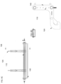
- FIGS. 7 A and 7 B represent perspective and side views of a jig assembly for welding the adapter assemblies of FIGS. 1 A through 6 D in accordance with a nonlimiting embodiment of this invention.
- FIGS. 8 A and 8 B represent perspective views of components of the adapter assembly of FIGS. 1 A and 3 A through 3 F assembled with the jig assembly of FIGS. 7 A and 7 B in preparation for welding.
- FIGS. 9 A and 9 B represent perspective views of components of the adapter assembly of FIGS. 2 A and 4 A through 4 F assembled with the jig assembly of FIGS. 7 A and 7 B in preparation for welding.
- FIGS. 10 through 20 represent views of implements and accessories coupled to the adapter assembly of FIGS. 1 A, 1 B, and 3 A through 3 F in accordance with nonlimiting embodiments of the present invention.
- FIGS. 21 and 22 represent side views attachment hooks for use with adapter assemblies in accordance with nonlimiting embodiments of this invention.
- FIGS. 23 and 24 represent perspective isolated views of the attachment hooks of FIGS. 21 and 22 , respectively.
- FIGS. 1 A and 1 B and FIGS. 2 A and 2 B represent perspective assembly and exploded views of two adapter assemblies 10 and 110 in accordance with nonlimiting embodiments of the invention.
- relative terms including but not limited to, “vertical,” “horizontal,” “lateral,” “front,” “rear,” “side,” “forward,” “rearward,” “upper,” “lower,” “above,” “below,” “right,” “left,” “inboard,” “outboard,” etc., may be used in reference to the orientation of each adapter assembly 10 and 110 when installed for use on a vehicle as represented in the drawings, and therefore are relative terms that indicate the construction, installation and use of the invention and therefore help to define the scope of the invention.
- the adapter assembly 10 of FIGS. 1 A and 1 B is represented as comprising a pair of vertically-spaced crossbars 12 A and 12 B maintained in vertical alignment with respect to each other by vertical legs 20 A of two pairs of L-shaped brackets 14 and 16 and a pair of spacer brackets 18 .
- the crossbars 12 A and 12 B are horizontal and parallel to each other, though other orientations are possible.
- Each L-shaped bracket 14 is adjacently paired with an L-shaped bracket 16 at oppositely-disposed outboard ends of the crossbars 12 A and 12 B, with the L-brackets 14 being most outboard on the assembly 10 .
- Each spacer bracket 18 is located inboard of an adjacent pair of the L-shaped brackets 14 and 16 .
- Each of the L-shaped bracket 16 and spacer brackets 18 has upper and lower holes 26 and 28 through which, respectively, the upper and lower crossbars 12 A and 12 B are received. Additionally, the vertical legs 20 A of each L-shaped bracket 14 and 16 and the vertical extent of each spacer bracket 18 has an array of holes 30 to provide locations for attachment. Installed in one aligned pair of these holes 30 are spring-loaded lock pins 36 for securing an attachment hook 40 , which is shown and will be described in reference to FIGS. 3 A through 3 F . Optional rings 34 are shown as mounted to the lower crossbar 12 B to provide additional locations for mounting accessories.
- Lower horizontal legs 20 B of adjacent pairs of the L-shaped brackets 14 and 16 are secured together with a mounting bar 22 therebetween, creating a subassembly of the brackets 14 and 16 having joined lower horizontal legs 20 B that define a lower leg unit that is sized to be received and secured within a channel 24 A defined by a mount 24 (in this case, a C-channel), for example, with a bolt 32 .
- the mount 24 is of a type for mounting a snow plow, for example, a Western brand snow plow. In this manner, the adapter assembly 10 can be easily and quickly installed on and removed from the mount 24 with the bolts 32 .
- the adapter assembly 110 of FIGS. 2 A and 2 B is similarly configured to the assembly 10 of FIGS. 1 A and 1 B . Differences between the assemblies 10 and 110 are attributable to being configured for attachment to a different style of mount, which in the case of the assembly 110 is a mount 124 comprising a vertically-oriented C-shaped bracket such as of a type for mounting a snow plow, for example, a Boss brand snow plow.
- a mount 124 comprising a vertically-oriented C-shaped bracket such as of a type for mounting a snow plow, for example, a Boss brand snow plow.
- consistent reference numbers are used to identify the same or functionally related/equivalent elements, but with a numerical prefix ( 1 ) added to distinguish the embodiment FIGS. 2 A and 2 B from the embodiment of FIGS. 1 A and 1 B .
- a numerical prefix 1
- FIGS. 1 A and 1 B will focus primarily on aspects of the second embodiment that differ from the first embodiment of FIGS. 1 A and 1 B in some notable or significant manner.
- Other aspects of the second embodiment not discussed in any detail can be, in terms of structure, function, materials, etc., essentially as was described for the first embodiment.
- the adapter assembly 110 of FIGS. 2 A and 2 B is represented as comprising a pair of vertically-spaced crossbars 112 A and 112 B maintained in vertical alignment with respect to each other by vertical legs 120 A of two pairs of L-shaped brackets 114 and 116 and a pair of spacer brackets 118 .
- Each L-shaped bracket 114 is adjacently paired with an L-shaped bracket 116 at oppositely-disposed outboard ends of the crossbars 112 A and 112 B, with the L-brackets 114 being most outboard of each pair.
- each spacer bracket 118 may be located on the assembly 110 outboard of an adjacent pair of the L-shaped brackets 114 and 116 . Consequently, each of the L-shaped brackets 114 and 116 has upper and lower holes 126 and 128 through which, respectively, the upper and lower crossbars 112 A and 112 B are received, whereas the spacer brackets 118 are not required to have holes for receiving the crossbars 112 A and 112 B.
- the vertical legs 120 A of each L-shaped bracket 114 and 116 and the vertical extent of each spacer bracket 118 has an array of holes 130 to provide locations for attachment.
- FIGS. 4 A through 4 F Installed in one aligned pair of these holes 130 are spring-loaded lock pins 136 for securing an attachment hook 140 , which is shown and will be described in reference to FIGS. 4 A through 4 F .
- Optional rings 134 are shown as mounted to the lower crossbar 112 B to provide additional locations for mounting accessories.
- Lower horizontal legs 120 B of adjacent pairs of the L-shaped brackets 114 and 116 are secured together with a mounting bar 122 therebetween, creating a subassembly of the brackets 114 and 116 , which are each further configured to have lower angular (neither vertical nor horizontal) legs 120 C that, as a result of the lower horizontal legs 120 B being joined, define a lower leg unit that is sized to be coupled to the mount 124 .
- each lower leg unit defined by the angular legs 120 C of a pair of brackets 114 and 116 is coupled to its corresponding mount 124 with at least one pin 132 that is fixed within a complementary pair of holes 138 A at a lower extremity of the angular legs 120 C, and is sized to be received in a cradle 124 A formed by its corresponding mount 124 .
- each lower leg unit defined by each pair of angular legs 120 C is coupled to its mount 124 with at least one pin, bolt, or other suitable structure (not shown) that is sized to be received in a complementary pair of holes 138 B at an upper extremity of the angular legs 120 C and a hole 124 B formed in its corresponding mount 124 .
- the adapter assembly 110 can be easily and quickly installed on and removed from the mount 124 with the pins (or other structure) received in the holes 138 B of the mount 124 .
- FIGS. 3 A through 3 F represent the assembly 10 of FIGS. 1 A and 1 B in combination with the aforementioned attachment hook 40
- FIGS. 4 A through 4 F represent the assembly 110 of FIGS. 2 A and 2 B in combination with the aforementioned attachment hook 140
- FIGS. 21 through 24 represent additional nonlimiting embodiments of attachment hooks 240 and 340 .
- the attachment hooks 40 , 140 , 240 , and 340 can be similarly configured if not identical, and/or may function in a substantially similar manner or for a substantially similar purpose.
- attachment hook 40 will be described, with the understanding that the description also applies to the attachment hooks 140 , 240 , and 340 , and that consistent reference numbers are used to identify the same or functionally related/equivalent elements of the hooks 40 , 140 , 240 , and 340 , but with a numerical prefix ( 1 , 2 , or 3 ) added to reference numbers used in respect to the hooks 140 , 240 , and 340 to distinguish the components of the hooks 140 , 240 , and 340 from the components of the hook 40 .
- the attachment hook 40 is represented as comprising a pair of vertically-spaced crossbars 42 A and 42 B maintained in vertical alignment with respect to each other by a pair of vertical brackets 44 .
- Each bracket 44 has an upper hook feature 46 located at or near its uppermost extent, and a lower hook feature 48 located at or near its lowermost extent.
- Both upper and lower hook features 46 and 48 are C-shaped, but the upper hook feature 46 defines an opening facing downward whereas the lower hook feature 48 defines an opening facing horizontally.
- Each bracket 44 comprises a boss 50 with a hole that can be engaged with a corresponding one of the spring-loaded lock pins 36 to secure the attachment hook 40 to the adapter assembly 10 . In this manner, the attachment hook 40 can be easily and quickly installed on and removed from the adapter assembly 10 .
- the L-shaped brackets 14 and 16 are located outboard of the spacer bracket 18 in the adapter assembly 10
- the L-shaped brackets 114 and 116 are located inboard of the spacer bracket 118 of the adapter assembly 110 .
- the vertical brackets 44 of the attachment hook 40 and their upper and lower hook features 46 and 48 are shown to engage the crossbars 12 A and 12 B adjacent the L-shaped brackets 14 at the outboard ends of the assembly 10
- the vertical brackets 144 of the attachment hook 140 and their upper and lower hook features 146 and 148 are shown to engage the crossbars 112 A and 112 B adjacent the spacer brackets 118 at the outboard ends of the assembly 110 .
- the attachment hook 40 can be permanently (or removably) attached to an accessory 60 , so that the accessory 60 and its attachment hook 40 can be easily and quickly installed on and removed from the adapter assembly 10 as a unit, and therefore also as a unit to and from a vehicle to which the mount 24 is secured.
- FIGS. 3 A through 3 F are equally applicable to the adapter assembly 110 and its attachment hook 140 of FIGS. 2 A, 2 B, and 4 A through 4 F .
- the attachment hooks 240 and 340 of FIGS. 21 through 24 may engage adapter assemblies similar or identical to the adapter assemblies 10 and 110 .
- FIGS. 21 and 23 represent the attachment hook 240 as comprising a pair of vertically-spaced crossbars 242 A and 242 B maintained in vertical alignment with respect to each other by a pair of brackets 244 .
- Each bracket 244 has an upper hook feature 246 located at or near its uppermost extent, and a lower hook feature 248 located at or near its lowermost extent.
- Both upper and lower hook features 246 and 248 are C-shaped. Unlike the upper and lower hook features 46 and 48 of the attachment hook 40 and the upper and lower hook features 146 and 148 of the attachment hook 140 , the upper and lower hook features 246 and 248 both define openings facing downward.
- the attachment hook 240 can be assembled with an adapter assembly by simultaneously engaging upper and lower crossbars thereof with the upper and lower features 246 and 248 , respectively.
- the attachment hook 240 includes an array of holes 252 to provide locations for attachment.
- the pair of vertically-spaced crossbars 242 A and 242 B are installed in respective ones of aligned pairs of these holes 252 .
- FIGS. 22 and 24 represent the attachment hook 340 as comprising a pair of vertically-spaced crossbars 342 A and 342 B maintained in vertical alignment with respect to each other by a pair of brackets 344 .
- Each bracket 344 includes a pair of recesses 354 configured to receive the pair of vertically-spaced crossbars 342 A and 342 B.
- FIGS. 5 A and 5 B provide plan and cross-sectional views of the adapter assembly 10 assembled with its attachment hook 40
- FIGS. 6 A through 6 D provide plan and cross-sectional views of the adapter assembly 110 assembled with its attachment hook 140 .
- FIGS. 7 A and 7 B represent a jig assembly 70 configured for securing individual components of the adapter assemblies 10 and 110 during the process of joining their components, for example, by welding.
- the jig assembly 70 is preferably capable of being universal for adapter assemblies of the types represented in FIGS. 1 A through 6 D .
- the jig assembly 70 is represented as comprising a base unit 72 and an upper unit 78 .
- the base unit 72 includes longitudinal members 73 interconnected with cross members 74 , and slots 76 are formed in upper edges of the longitudinal members 73 that are positioned and sized to receive lower edges of the six L-shaped and spacer brackets 14 , 16 , and 18 of the adapter assembly 10 as shown in FIGS.
- the jig assembly 70 is configured to be universal as a result of locating the two sets of six brackets 14 , 16 , 18 , 114 , 116 , and 118 within their respective assemblies 10 and 110 so that eight slots 76 on each member 73 are able to accommodate the positions of all six brackets of both assemblies 10 and 110 , as evident from FIGS.
- the upper unit 78 of the jig assembly 70 has slots 80 formed in its lower edge that are positioned and sized to receive upper edges of the L-shaped and spacer brackets 14 , 16 , and 18 of the adapter assembly 10 as shown in FIGS. 8 A and 8 B , as well as upper edges of the L-shaped and spacer brackets 114 , 116 , and 118 of the adapter assembly 110 as shown in FIGS. 9 A and 9 B .
- the longitudinal members 72 are preferably spaced laterally apart by the cross members 74 so that the crossbars 12 A and 12 B of the adapter assembly 10 and the crossbars 112 A and 112 B of the adapter assembly 110 are suspended laterally from the jig assembly 70 , so that the longitudinal members 72 support the entire weight of the adapter assemblies 10 and 110 during welding.
- FIGS. 10 through 20 represent views of nonlimiting examples of implements and accessories that can be coupled to the adapter assemblies of the types represented in FIGS. 1 A through 9 B .
- the implements/accessories are shown in conjunction with the assembly 10 , it should be appreciated that, due to the similarities of the attachment hooks 40 and 140 , the implements/accessories shown in FIGS. 10 through 20 can be equally used in conjunction with the assembly 110 .
- FIGS. 10 , 11 , 12 , 13 A, and 13 B depict implements/accessories that can be permanently attached to the attachment hook 40 to enable each implement/accessory and its attachment hook 40 to be installed and removed from the adapter assembly 10 as a unit.
- FIG. 10 depicts a carrier 90 adapted for transporting small wheeled equipment and vehicles, such as a scooter.
- FIGS. 11 A and 11 B depict a toolbox 92
- FIG. 12 depicts a water tank 94 .
- FIGS. 13 A and 13 B depict a service platform 103 with an adjustable tool tray 104 mounted thereto.
- the service platform 103 includes a pair of vertical plates 105 that are attached to the attachment hook 40 .
- FIGS. 14 through 20 depict implements/accessories that can be attached directly to the adapter assembly 10 without the attachment hook 40 .
- FIG. 14 depicts a grill guard 96 mounted by bolting vertical bars 97 of the guard 96 to the outboard L-shaped brackets 14 by utilizing the holes 30 preformed in the brackets 14 .
- FIGS. 15 A and 15 B depict the grill guard 96 with the addition of a winch mount 98 that has been coupled to the adapter assembly 10 with the attachment hook 40 .
- FIG. 16 depicts outboard cone carriers 99 mounted by bolting vertical bars 100 of the carriers 99 to the outboard L-shaped brackets 14 by utilizing the holes 30 preformed in the brackets 14 .
- FIGS. 17 and 18 depict, respectively, an inboard light bar 101 and an inboard hitch receiver 102 that are similarly mounted by bolting to the spacer brackets 18 utilizing the holes 30 preformed in the brackets 18 .
- FIGS. 19 and 20 depict outboard cone carriers 103 mounted by bolting angled bars 105 of the carriers 103 to the outboard L-shaped brackets 14 by utilizing the holes 30 preformed in the brackets 14 .
- the carriers 103 include adjustable cone holders 104 for securing cones during transport.
- Suitable materials for use in the construction of the assemblies 10 and 110 , attachment hooks 40 and 140 , and implements and accessories include aluminum alloys and iron-based alloys including stainless steels.
- methods for mounting an implement or accessory to a front end of a vehicle that has a mount 24 or 124 attached to a frame of the vehicle may include coupling the lower legs 20 B or 120 C of the pair of L-shaped brackets 14 and 16 or 114 and 116 to the mount 24 or 124 attached to the frame of the vehicle.
- the upper and lower crossbars 12 A and 12 B or 112 A and 112 B are horizontally oriented and spaced vertically apart from each other relative to the vehicle.
- the mount 24 comprises a C-channel
- the lower legs 20 B may be received in the channel 24 A of the mount 24 and secured therein, for example, with the bolt 32 .
- the mount 24 comprises a vertically-oriented C-shaped bracket 124
- the lower legs 120 C may be received in the cradle 124 A of the mount 124 and secured thereto.
- at least one pin 132 that is fixed within the complementary pair of holes 138 A at a lower extremity of the angular legs 120 C may be received in the cradle 124 A formed by its corresponding mount 124 .
- Each lower leg unit defined by each pair of angular legs 120 C may then be coupled to its mount 124 with at least one pin, bolt, or other suitable structure (not shown) that is sized to be received in the complementary pair of holes 138 B at an upper extremity of the angular legs 120 C and a hole 124 B formed in its corresponding mount 124 .
- the attachment hook 40 or 140 may be releasably coupled to the adapter assembly 10 or 110 , for example, as described in relation to FIGS. 3 A through 3 F and 4 A through 4 F .
- the upper hook feature 46 or 146 of the attachment hook 40 or 140 may be pivotally engaged to the upper crossbar 12 A or 112 A and the lower hook feature 48 or 148 may be engaged the lower crossbar 12 B or 112 B.
- At least one boss 50 of the attachment hook 40 or 140 may engage at least one spring-loaded lock pin 36 or 136 of the adapter assembly 10 or 110 to secure the attachment hook 40 or 140 to the adapter assembly 10 or 110 .
- One or more implements and/or accessories may be directly attached to one or more of the L-shaped and spacer brackets 14 , 16 , and 18 or 114 , 116 , and 118 of the adapter assembly 10 or 110 and/or directly attached to the attachment hook 40 or 140 so as to be releasably mounted to the adapter assembly 10 or 110 .
- Such implements and/or accessories may be attached to the adapter assembly 10 or 110 and/or the attachment hook 40 or 140 prior to or after coupling the attachment hook 40 or 140 to the adapter assembly 10 or 110 .
Landscapes
- Engineering & Computer Science (AREA)
- Civil Engineering (AREA)
- Structural Engineering (AREA)
- Mechanical Engineering (AREA)
- Mining & Mineral Resources (AREA)
- General Engineering & Computer Science (AREA)
- Architecture (AREA)
- Fittings On The Vehicle Exterior For Carrying Loads, And Devices For Holding Or Mounting Articles (AREA)
Abstract
Description
Claims (18)
Priority Applications (2)
| Application Number | Priority Date | Filing Date | Title |
|---|---|---|---|
| US17/237,721 US12139866B2 (en) | 2020-04-28 | 2021-04-22 | Adapter assemblies and methods for mounting implements and accessories to passenger vehicles therewith |
| CA3116172A CA3116172C (en) | 2020-04-28 | 2021-04-26 | Adapter assemblies and methods for mounting implements and accessories to passenger vehicles therewith |
Applications Claiming Priority (2)
| Application Number | Priority Date | Filing Date | Title |
|---|---|---|---|
| US202063016479P | 2020-04-28 | 2020-04-28 | |
| US17/237,721 US12139866B2 (en) | 2020-04-28 | 2021-04-22 | Adapter assemblies and methods for mounting implements and accessories to passenger vehicles therewith |
Publications (2)
| Publication Number | Publication Date |
|---|---|
| US20210332543A1 US20210332543A1 (en) | 2021-10-28 |
| US12139866B2 true US12139866B2 (en) | 2024-11-12 |
Family
ID=78221849
Family Applications (1)
| Application Number | Title | Priority Date | Filing Date |
|---|---|---|---|
| US17/237,721 Active 2043-04-27 US12139866B2 (en) | 2020-04-28 | 2021-04-22 | Adapter assemblies and methods for mounting implements and accessories to passenger vehicles therewith |
Country Status (2)
| Country | Link |
|---|---|
| US (1) | US12139866B2 (en) |
| CA (1) | CA3116172C (en) |
Families Citing this family (1)
| Publication number | Priority date | Publication date | Assignee | Title |
|---|---|---|---|---|
| US20250010802A1 (en) * | 2023-07-05 | 2025-01-09 | Sean Lloyd | Bull bar attachment system |
Citations (15)
| Publication number | Priority date | Publication date | Assignee | Title |
|---|---|---|---|---|
| US3417886A (en) * | 1967-06-07 | 1968-12-24 | Clifton F. Stuart | Implement hitch for tractors and loaders |
| US3760883A (en) * | 1972-03-27 | 1973-09-25 | Balderson Inc | Quick hitch assembly |
| US3887096A (en) * | 1973-10-11 | 1975-06-03 | Lloyd R Wieland | Quick attachment and release device |
| US4013182A (en) * | 1975-04-21 | 1977-03-22 | Rockland, Inc. | Detachable coupling system |
| US4030624A (en) * | 1975-01-04 | 1977-06-21 | Massey-Ferguson Services N.V. | Loader vehicles |
| US4068959A (en) * | 1976-11-26 | 1978-01-17 | Pemberton Bruce W | Coupler apparatus |
| US4243356A (en) * | 1978-03-30 | 1981-01-06 | Caterpillar Mitsubishi Ltd. | Quick coupler |
| US4715770A (en) * | 1984-10-25 | 1987-12-29 | Deere & Company | Power lift for a lifting device |
| US4773666A (en) * | 1986-06-16 | 1988-09-27 | Worksaver Inc. | Tractor hitch with improved mounting means |
| US5010962A (en) * | 1990-04-30 | 1991-04-30 | Caterpillar Inc. | Indicating apparatus for a coupling |
| US5419673A (en) * | 1993-03-11 | 1995-05-30 | Memo Industrial Planning, Inc. | Quick disconnect apparatus for tractor front loader |
| US5692855A (en) * | 1994-06-21 | 1997-12-02 | Farmers' Factory Co. | Automatic quick-connect coupler for implements |
| US8117773B2 (en) * | 2008-10-28 | 2012-02-21 | Paladin Brands Group, Inc. | Dual cylinder dual pick-up coupler |
| US8689898B2 (en) * | 2010-01-09 | 2014-04-08 | Brian Anthony Benesch | Removable loader for all-terrain and utility-terrain vehicles |
| US8777546B2 (en) * | 2010-03-05 | 2014-07-15 | Deere & Company | System for attaching a tool to a work machine |
-
2021
- 2021-04-22 US US17/237,721 patent/US12139866B2/en active Active
- 2021-04-26 CA CA3116172A patent/CA3116172C/en active Active
Patent Citations (15)
| Publication number | Priority date | Publication date | Assignee | Title |
|---|---|---|---|---|
| US3417886A (en) * | 1967-06-07 | 1968-12-24 | Clifton F. Stuart | Implement hitch for tractors and loaders |
| US3760883A (en) * | 1972-03-27 | 1973-09-25 | Balderson Inc | Quick hitch assembly |
| US3887096A (en) * | 1973-10-11 | 1975-06-03 | Lloyd R Wieland | Quick attachment and release device |
| US4030624A (en) * | 1975-01-04 | 1977-06-21 | Massey-Ferguson Services N.V. | Loader vehicles |
| US4013182A (en) * | 1975-04-21 | 1977-03-22 | Rockland, Inc. | Detachable coupling system |
| US4068959A (en) * | 1976-11-26 | 1978-01-17 | Pemberton Bruce W | Coupler apparatus |
| US4243356A (en) * | 1978-03-30 | 1981-01-06 | Caterpillar Mitsubishi Ltd. | Quick coupler |
| US4715770A (en) * | 1984-10-25 | 1987-12-29 | Deere & Company | Power lift for a lifting device |
| US4773666A (en) * | 1986-06-16 | 1988-09-27 | Worksaver Inc. | Tractor hitch with improved mounting means |
| US5010962A (en) * | 1990-04-30 | 1991-04-30 | Caterpillar Inc. | Indicating apparatus for a coupling |
| US5419673A (en) * | 1993-03-11 | 1995-05-30 | Memo Industrial Planning, Inc. | Quick disconnect apparatus for tractor front loader |
| US5692855A (en) * | 1994-06-21 | 1997-12-02 | Farmers' Factory Co. | Automatic quick-connect coupler for implements |
| US8117773B2 (en) * | 2008-10-28 | 2012-02-21 | Paladin Brands Group, Inc. | Dual cylinder dual pick-up coupler |
| US8689898B2 (en) * | 2010-01-09 | 2014-04-08 | Brian Anthony Benesch | Removable loader for all-terrain and utility-terrain vehicles |
| US8777546B2 (en) * | 2010-03-05 | 2014-07-15 | Deere & Company | System for attaching a tool to a work machine |
Also Published As
| Publication number | Publication date |
|---|---|
| CA3116172C (en) | 2023-08-01 |
| CA3116172A1 (en) | 2021-10-28 |
| US20210332543A1 (en) | 2021-10-28 |
Similar Documents
| Publication | Publication Date | Title |
|---|---|---|
| US4646952A (en) | Method and apparatus for carrying a load with a motor vehicle | |
| US8033563B2 (en) | Universal platform hitch assembly system | |
| US8668124B2 (en) | Variable width headache rack and assembly with interchangeable screens | |
| US6019266A (en) | Bicycle carrier for vehicle | |
| US5497927A (en) | Bicycle rack | |
| US6095387A (en) | Multipurpose carrier | |
| CA2541084C (en) | Mating receiver rack for personal recreational vehicles | |
| US4204701A (en) | Universal quick detach accessory mount for vehicles or the like | |
| US5836493A (en) | Vehicular mount for cargo carrier | |
| US5269446A (en) | Bicycle rack for recreational vehicle | |
| WO2002034569A2 (en) | Accessory mounting system for trailer hitch assembly | |
| US6851695B2 (en) | Base rail kit for motor vehicle | |
| US20020148867A1 (en) | Atv carrier rack | |
| US7198443B2 (en) | Motorcycle transport system and method therefor | |
| US6931770B2 (en) | Front equipment mount for a wheeled vehicle | |
| US12139866B2 (en) | Adapter assemblies and methods for mounting implements and accessories to passenger vehicles therewith | |
| CA2585744A1 (en) | Tow trailer assembly | |
| US9745006B2 (en) | Upright receiver assembly for attachment to trailer and methods of use | |
| US5007567A (en) | Support rack for bicycles and the like | |
| US8672048B2 (en) | Tractor pull bar mounting bracket assembly | |
| US8430286B1 (en) | Boat carrying rack for use on transporting vehicles | |
| US20110226830A1 (en) | Winch tray mounting system for vehicles | |
| US8016313B2 (en) | Tow rack | |
| WO2006037147A1 (en) | A trailer | |
| US4664489A (en) | Auxiliary mirror system |
Legal Events
| Date | Code | Title | Description |
|---|---|---|---|
| FEPP | Fee payment procedure |
Free format text: ENTITY STATUS SET TO UNDISCOUNTED (ORIGINAL EVENT CODE: BIG.); ENTITY STATUS OF PATENT OWNER: SMALL ENTITY |
|
| FEPP | Fee payment procedure |
Free format text: ENTITY STATUS SET TO SMALL (ORIGINAL EVENT CODE: SMAL); ENTITY STATUS OF PATENT OWNER: SMALL ENTITY |
|
| STPP | Information on status: patent application and granting procedure in general |
Free format text: DOCKETED NEW CASE - READY FOR EXAMINATION |
|
| AS | Assignment |
Owner name: JOHNSTON LANDSCAPE MAINTENANCE INC., INDIANA Free format text: ASSIGNMENT OF ASSIGNORS INTEREST;ASSIGNORS:JOHNSTON, RICHARD HARTLEY;SINN, DAVID ANDREW;REEL/FRAME:058882/0375 Effective date: 20211118 |
|
| STPP | Information on status: patent application and granting procedure in general |
Free format text: NON FINAL ACTION MAILED |
|
| STPP | Information on status: patent application and granting procedure in general |
Free format text: RESPONSE TO NON-FINAL OFFICE ACTION ENTERED AND FORWARDED TO EXAMINER |
|
| STPP | Information on status: patent application and granting procedure in general |
Free format text: FINAL REJECTION MAILED |
|
| STPP | Information on status: patent application and granting procedure in general |
Free format text: RESPONSE AFTER FINAL ACTION FORWARDED TO EXAMINER |
|
| STPP | Information on status: patent application and granting procedure in general |
Free format text: NOTICE OF ALLOWANCE MAILED -- APPLICATION RECEIVED IN OFFICE OF PUBLICATIONS |
|
| ZAAB | Notice of allowance mailed |
Free format text: ORIGINAL CODE: MN/=. |
|
| STPP | Information on status: patent application and granting procedure in general |
Free format text: PUBLICATIONS -- ISSUE FEE PAYMENT VERIFIED |
|
| STCF | Information on status: patent grant |
Free format text: PATENTED CASE |