US12136183B2 - Demosaicing method and demosaicing device - Google Patents
Demosaicing method and demosaicing device Download PDFInfo
- Publication number
- US12136183B2 US12136183B2 US17/335,970 US202117335970A US12136183B2 US 12136183 B2 US12136183 B2 US 12136183B2 US 202117335970 A US202117335970 A US 202117335970A US 12136183 B2 US12136183 B2 US 12136183B2
- Authority
- US
- United States
- Prior art keywords
- image
- color difference
- color
- pixel
- green
- Prior art date
- Legal status (The legal status is an assumption and is not a legal conclusion. Google has not performed a legal analysis and makes no representation as to the accuracy of the status listed.)
- Active, expires
Links
Images


Classifications
-
- G—PHYSICS
- G06—COMPUTING OR CALCULATING; COUNTING
- G06T—IMAGE DATA PROCESSING OR GENERATION, IN GENERAL
- G06T3/00—Geometric image transformations in the plane of the image
- G06T3/40—Scaling of whole images or parts thereof, e.g. expanding or contracting
- G06T3/4015—Image demosaicing, e.g. colour filter arrays [CFA] or Bayer patterns
-
- G—PHYSICS
- G06—COMPUTING OR CALCULATING; COUNTING
- G06N—COMPUTING ARRANGEMENTS BASED ON SPECIFIC COMPUTATIONAL MODELS
- G06N3/00—Computing arrangements based on biological models
- G06N3/02—Neural networks
- G06N3/04—Architecture, e.g. interconnection topology
- G06N3/045—Combinations of networks
-
- G—PHYSICS
- G06—COMPUTING OR CALCULATING; COUNTING
- G06N—COMPUTING ARRANGEMENTS BASED ON SPECIFIC COMPUTATIONAL MODELS
- G06N3/00—Computing arrangements based on biological models
- G06N3/02—Neural networks
- G06N3/08—Learning methods
-
- G06T11/001—
-
- G—PHYSICS
- G06—COMPUTING OR CALCULATING; COUNTING
- G06T—IMAGE DATA PROCESSING OR GENERATION, IN GENERAL
- G06T11/00—Two-dimensional [2D] image generation
- G06T11/10—Texturing; Colouring; Generation of textures or colours
-
- G—PHYSICS
- G06—COMPUTING OR CALCULATING; COUNTING
- G06T—IMAGE DATA PROCESSING OR GENERATION, IN GENERAL
- G06T3/00—Geometric image transformations in the plane of the image
- G06T3/40—Scaling of whole images or parts thereof, e.g. expanding or contracting
- G06T3/4046—Scaling of whole images or parts thereof, e.g. expanding or contracting using neural networks
-
- G—PHYSICS
- G06—COMPUTING OR CALCULATING; COUNTING
- G06T—IMAGE DATA PROCESSING OR GENERATION, IN GENERAL
- G06T7/00—Image analysis
- G06T7/90—Determination of colour characteristics
-
- G—PHYSICS
- G06—COMPUTING OR CALCULATING; COUNTING
- G06T—IMAGE DATA PROCESSING OR GENERATION, IN GENERAL
- G06T2207/00—Indexing scheme for image analysis or image enhancement
- G06T2207/10—Image acquisition modality
- G06T2207/10024—Color image
-
- G—PHYSICS
- G06—COMPUTING OR CALCULATING; COUNTING
- G06T—IMAGE DATA PROCESSING OR GENERATION, IN GENERAL
- G06T2207/00—Indexing scheme for image analysis or image enhancement
- G06T2207/20—Special algorithmic details
- G06T2207/20081—Training; Learning
-
- G—PHYSICS
- G06—COMPUTING OR CALCULATING; COUNTING
- G06T—IMAGE DATA PROCESSING OR GENERATION, IN GENERAL
- G06T2207/00—Indexing scheme for image analysis or image enhancement
- G06T2207/20—Special algorithmic details
- G06T2207/20084—Artificial neural networks [ANN]
Definitions
- Example embodiments relate generally to image processing. More particularly, example embodiments relate to a demosaicing method and demosaicing device.
- Each pixel in an image sensor detects one color, and other colors of each pixel may be obtained through interpolation of pixel values of neighboring pixels. Such color interpolation is referred to as demosaicing.
- a demosaicing method of reconstructing omitted color pixel values causes a block noise such as zipper effect, random color dot, etc.
- noise filtering and edge blurring.
- the interpolation of an omitted pixel value using neighboring pixel values may blur areas near edges of an image when the pixel values are interpolated near the edges in the image.
- Such problems result from averaging of color pixel values across the edge, such as when color pixel values on two sides of an edge sharply differ and the averaging greatly reduces the sharp difference to produce the blurring.
- CFA color filter array
- Some example embodiments may provide a demosaicing method based on deep learning and capable of enhancing image detail and reducing image artifact.
- Some example embodiments may provide a demosaicing device performing the demosaicing method based on deep learning.
- a demosaicing method based on deep learning includes providing an artificial neural network configured to convert a mosaic image representable by pixels with color pixel values corresponding to a plurality of colors to a plurality of color difference images corresponding to the plurality of colors.
- the demosaicing method also includes generating a plurality of output color difference images corresponding to the plurality of colors based on an input mosaic image representable by pixels with color pixel values corresponding to the plurality of colors using the artificial neural network.
- the demosaicing method further includes generating a plurality of demosaiced color images corresponding to the plurality of colors by summing, pixel by pixel, the input mosaic image and each of the plurality of output color difference images.
- a demosaicing device includes an adder circuit and a memory that stores an artificial neural network.
- the artificial neural network generates a plurality of output color difference images corresponding to the plurality of colors based on an input mosaic image representable by pixels with color pixel values corresponding to the plurality of colors.
- the adder circuit generates a plurality of demosaiced color images corresponding to the plurality of colors by summing, pixel by pixel, the input mosaic image and each of the plurality of output color difference images.
- a demosaicing method based on deep learning includes providing an artificial neural network configured to convert a mosaic image representable by pixels with red pixel values, green pixel values and blue pixel values to three color difference images corresponding to a red color, a green color and a blue color.
- the demosaicing method also includes generating three output color difference images corresponding to the red color, the green color and the blue color based on an input mosaic image representable by pixels with red pixel values, green pixel values, and blue pixel values using the artificial neural network.
- the demosaicing method further includes generating three demosaiced color images corresponding to the red color, the green color, and the blue color by summing, pixel by pixel, the input mosaic image and each of the three output color difference images.
- the demosaicing method and the demosaicing device may reduce image artifact and enhance image quality.
- Image quality may be enhanced by generating the color difference images using the artificial neural network having enhanced nonlinearity and by restoring the demosaiced color images simultaneously based on the color difference images.
- FIG. 1 is a flow chart illustrating a demosaicing method based on deep learning according to example embodiments.
- FIG. 2 is a diagram illustrating a demosaicing device according to example embodiments.
- FIG. 3 is a diagram illustrating an example embodiment of an adder circuit included in the demosaicing device of FIG. 2 .
- FIG. 4 and FIG. 5 are diagrams illustrating images in a demosaicing method based on deep learning according to example embodiments.
- FIG. 6 is a flow chart illustrating an example embodiment of generating demosaiced color images in a demosaicing method based on deep learning according to example embodiments.
- FIG. 7 is a diagram illustrating color patterns applicable to a demosaicing method based on deep learning according to example embodiments.
- FIG. 8 and FIG. 9 are diagrams illustrating images in a demosaicing method based on deep learning according to example embodiments.
- FIG. 10 and FIG. 11 are diagrams for describing examples of a deep learning neural network structure that is driven by a machine learning device according to example embodiments.
- FIG. 12 is a diagram illustrating an example of a node included in a neural network
- FIG. 13 is a flow chart illustrating an example embodiment of training an artificial neural network in a demosaicing method based on deep learning according to example embodiments.
- FIG. 14 is a diagram illustrating images in training the artificial neural network of FIG. 13 .
- FIG. 15 is a flow chart illustrating an example embodiment of updating parameters of an artificial neural network in a demosaicing method based on deep learning according to example embodiments.
- FIG. 16 is a diagram for describing the parameter updating of FIG. 15 .
- FIG. 17 is a block diagram illustrating a structure of an artificial neural network for a demosaicing method based on deep learning according to example embodiments.
- FIG. 18 and FIG. 19 are diagrams illustrating effects of a demosaicing method based on deep learning according to example embodiments.
- FIG. 20 is a block diagram illustrating a system performing a demosaicing method based on deep learning according to example embodiments.
- FIG. 21 is a block diagram illustrating an example embodiment of an interface employable in the system of FIG. 20 according to example embodiments.
- FIG. 1 is a flow chart illustrating a demosaicing method based on deep learning according to example embodiments.
- an artificial neural network is provided, which is configured to convert a mosaic image representable by pixels with color pixel values corresponding to a plurality of colors to a plurality of color difference images corresponding to the plurality of colors (S 100 ). That is, the mosaic image may be a digital image composed of pixels with color pixel values when rendered on a display, but the underlying mosaic image may be more broadly described as being representable by pixels with color pixel values. According to the present disclosure, this relationship may be stated as, for example, an image including pixel values, such as a mosaic image including color pixel values.
- the artificial neural network may simultaneously generate the plurality of color difference images by performing a nonlinear operation on the color pixel values of the input mosaic image.
- the training of the artificial neural network will be described with reference to FIG. 10 through FIG. 17 .
- a plurality of output color difference images corresponding to the plurality of colors are generated based on an input mosaic image representable by pixels with color pixel values corresponding to the plurality of colors using the artificial neural network (S 200 ). That is, the artificial neural network is applied to the input mosaic image to generate the plurality of output color difference images.
- the color difference pixel value corresponding to a first color pixel value of the input mosaic image may have a value of zero, and the color difference pixel value corresponding to a second color pixel of the input mosaic image may have a value corresponding to a difference between a first color component and a second color component.
- the color difference pixel values included in the output color difference images will be described below with reference to FIG. 4 and FIG. 8 .
- a plurality of demosaiced color images corresponding to the plurality of colors are generated by summing, pixel by pixel, the input mosaic image and each of the plurality of output color difference images (S 300 ).
- the color pixel values of the plurality of demosaiced color images may be generated such that each color pixel value of the plurality of demosaiced color images corresponds to a sum of each color difference pixel value of the plurality of output color difference images and each color pixel value of the input mosaic image.
- the restoring of the plurality of demosaiced color images using the plurality of output color difference images will be described with reference to FIG. 5 and FIG. 9 .
- FIG. 2 is a diagram illustrating a demosaicing device according to example embodiments.
- a demosaicing device 100 may include an adder circuit 120 and a memory that stores an artificial neural network 110 (NTW).
- NTN artificial neural network 110
- the artificial neural network 110 may convert a mosaic image representable by pixels with color pixel values corresponding to a plurality of colors to a plurality of color difference images corresponding to the plurality of colors.
- the artificial neural network 110 may be provided as a program of software instructions executable by a processor of the demosaicing device 100 .
- the artificial neural network 110 may generate a plurality of output color difference images Icd 1 , Icd 2 and Icd 3 corresponding to the plurality of colors based on an input mosaic image Im including color pixel values corresponding to the plurality of colors.
- the plurality of output color difference images Icd 1 , Icd 2 and Icd 3 include a first output color difference image Icd 1 , a second output color difference image Icd 2 , and a third output color difference image Icd 3 .
- the artificial neural network 110 may simultaneously generate the plurality of output color difference images Icd 1 , Icd 2 and Icd 3 by performing a nonlinear operation on the color pixel values of the input mosaic image Im.
- the adder circuit 120 may generate a plurality of demosaiced color images Id 1 , Id 2 and Id 3 corresponding to the plurality of colors by summing, pixel by pixel, the input mosaic image Im and each of the plurality of output color difference images Icd 1 , Icd 2 and Icd 3 .
- the plurality of demosaiced color images Id 1 , Id 2 and Id 3 include a first demosaiced color image Id 1 , a second demosaiced color image Id 2 , and a third demosaiced color image Id 3 .
- the adder circuit 120 may generate the color pixel values of the plurality of demosaiced color images Id 1 , Id 2 and Id 3 by summing, pixel by pixel, the color difference pixel values of each of the plurality of output color difference images Icd 1 , Icd 2 and Icd 3 and the color pixel values of the input mosaic image Im.
- the demosaicing method and the demosaicing device may reduce image artifact and enhance image quality.
- Image quality may be enhanced by generating the color difference images using the artificial neural network having enhanced nonlinearity and by restoring the demosaiced color images simultaneously based on the color difference images.
- FIG. 3 is a diagram illustrating an example embodiment of an adder circuit included in the demosaicing device of FIG. 2 .
- an adder circuit 120 may include a first adder1 121 (PWA1), a second adder 122 (PWA2) and a third adder 123 (PWA3).
- FIG. 3 illustrates three color adders for convenience of illustration and description, and the number of color adders included in the adder circuit 120 may be determined variously depending on a color pattern of the input mosaic image Im to be demosaiced.
- the three color adders in FIG. 3 may correspond to a red color adder configured to generate red pixel values of a demosaiced red image, a green color adder configured to generate green pixel values of a demosaiced green image, and a blue color adder configured to generate blue pixel values of a demosaiced blue image.
- the adder circuit 120 may receive, from the artificial neural network 110 , the first output color difference image Icd 1 for restoring the first demosaiced color image Id 1 , the second output color difference image Icd 2 for restoring the second demosaiced color image Id 2 and the third output color difference image Icd 3 for restoring the third demosaiced color image Id 3 .
- the first adder 121 may be the red color adder and may generate color pixel values of the first demosaiced color image Id 1 by summing, pixel by pixel, color difference pixel values of the first output color difference image Icd 1 and the color pixel values of the input mosaic image Im.
- the second adder 122 may be the green color adder and may generate color pixel values of the second demosaiced color image Id 2 by summing, pixel by pixel, color difference pixel values of the second output color difference image Icd 2 and the color pixel values of the input mosaic image Im.
- the third adder 123 may be the blue color adder and may generate color pixel values of the third demosaiced color image Id 3 by summing, pixel by pixel, color difference pixel values of the third output color difference image Icd 3 and the color pixel values of the input mosaic image Im.
- FIG. 3 illustrates the adder circuit 120 that includes a plurality of color adders to perform pixel-wise additions in parallel, but example embodiments are not limited thereto.
- the adder circuit 120 may include a buffer and a single adder.
- the buffer may receive and buffer a plurality of color difference images that are provided simultaneously from the artificial neural network, and may sequentially output the plurality of color difference images such that the single adder may perform the pixel-wise addition sequentially with respect to the plurality of colors.
- example embodiments are described based on an input mosaic image representable by pixels with red pixel values R, green pixel values G and blue pixel values B, but example embodiments are not limited thereto.
- the number of pixels in an image and the color pattern of the input mosaic image are not limited to those illustrated in figures of this disclosure.
- FIG. 4 and FIG. 5 are diagrams illustrating images in a demosaicing method based on deep learning according to example embodiments. For convenience of illustration, only three pixels corresponding to a red color R, a green color G and a blue color B are illustrated in FIG. 4 and FIG. 5 .
- the artificial neural network 110 in FIG. 2 may simultaneously generate color difference images Icdr, Icdg and Icdb.
- the color difference images Icdr, Icdg and Icdb include a red color difference image Icdr for restoring a demosaiced red image Idr, a green color difference image Icdg for restoring a demosaiced green image Idg and a blue color difference image Icdb for restoring a demosaiced blue image Idb.
- the color difference pixel value RR corresponding to a red pixel value R of the input mosaic image Im may have a value of zero.
- the color difference pixel value RG corresponding to a green pixel value G of the input mosaic image Im may have a value corresponding to a difference R′ ⁇ G′ between a red component R′ and a green component G′.
- the color difference pixel value RB corresponding to a blue pixel value B of the input mosaic image Im may have a value corresponding to a difference R′ ⁇ B′ between a red component R′ and a blue component B′.
- the color difference pixel value GR corresponding to a red pixel value R of the input mosaic image Im may have a value corresponding to a difference G′ ⁇ R′ between a green component G′ and a red component R′.
- the color difference pixel value GG corresponding to a green pixel value G of the input mosaic image Im may have a value of zero.
- the color difference pixel value GB corresponding to a blue pixel value B of the input mosaic image Im may have a value corresponding to a difference G′ ⁇ B′ between a green component G′ and a blue component B′.
- the color difference pixel value BR corresponding to a red pixel value R of the input mosaic image Im may have a value corresponding to a difference B′ ⁇ R′ between a blue component B′ and a red component R′.
- the color difference pixel value BG corresponding to a green pixel value G of the input mosaic image Im may have a value corresponding to a difference B′ ⁇ G′ between a blue component B′ and a green component G′.
- the color difference pixel value BB corresponding to a blue pixel value B of the input mosaic image Im may have a value of zero.
- the adder circuit 120 in FIG. 2 may generate the demosaiced red image Idr, the demosaiced green image Idg and the demosaiced blue image Idb by summing, pixel by pixel, each of the red color difference image Icdr, green color difference image Icdg and the blue color difference image Icdb and the input mosaic image Im.
- the adder circuit 120 may generate each color pixel value of the demosaiced color images Idr, Idg and Idb by summing each color difference pixel value of the color difference images Icdr, Icdg and Icdb and each color pixel value of the input mosaic image Im.
- the red components R′, the green components G′ and the blue components B′ in FIG. 4 may approach red pixel values, green pixel values and blue pixel values of a ground truth demosaiced image as performance of the artificial neural network is enhanced.
- the value of zero of the color difference pixel values RR, GG and BB are ideal values, but the values of the color difference pixel values RR, GG and BB do not necessarily have to be zero depending on the artificial neural network.
- the adder circuit 120 may generate each color pixel value of the demosaiced color images Idr, Idg and Idb by performing the pixel-wise addition of the input mosaic image Im and each of the color difference images Icdr, Icdg and Icdb.
- FIG. 6 is a flow chart illustrating an example embodiment of generating demosaiced color images in a demosaicing method based on deep learning according to example embodiments.
- the red pixel values R 1 , R 2 and R 3 of the demosaiced red image Idr may be generated by summing, pixel by pixel, the color difference pixel values RR, RG and RB of the red color difference image Icdr and the color pixel values R, G and B of the input mosaic image Im (S 310 ).
- the green pixel values G 1 , G 2 and G 3 of the demosaiced green image Idg may be generated by summing, pixel by pixel, the color difference pixel values GR, GG and GB of the green color difference image Icdg and the color pixel values R, G and B of the input mosaic image Im (S 320 ).
- the blue pixel values B 1 , B 2 and B 3 of the demosaiced blue image Idb may be generated by summing, pixel by pixel, the color difference pixel values BR, BG and BB of the blue color difference image Icdb and the color pixel values R, G and B of the input mosaic image Im (S 330 ).
- the processes S 310 , S 320 and S 330 are not necessarily performed in the order illustrated in FIG. 6 . According to example embodiments, the processes S 310 , S 320 and S 330 may be sequentially performed in an order different from FIG. 6 , or two or all three of the processes S 310 , S 320 and S 330 may be performed simultaneously.
- the generation of the red pixel values R 1 , R 2 and R 3 (S 310 ), the generation of the green pixel values G 1 , G 2 and G 3 (S 320 ) and the generation of the blue pixel values B 1 , B 2 and B 3 (S 330 ) may be performed simultaneously using the first adder 121 , the second adder 122 and the third adder 123 as described with reference to FIG. 3 .
- the generation of the red pixel values R 1 , R 2 and R 3 (S 310 ), the generation of the green pixel values G 1 , G 2 and G 3 (S 320 ) and the generation of the blue pixel values B 1 , B 2 and B 3 (S 330 ) may be performed sequentially using a buffer and a single adder.
- FIG. 7 is a diagram illustrating color patterns applicable to a demosaicing method based on deep learning according to example embodiments.
- FIG. 7 illustrates, as examples, unit structures of a Bayer pattern PTT 1 , a Tetra pattern PTT 2 , a Nona pattern PTT 3 , and an RGBW pattern PTT 4 .
- a unit structure indicates a minimum arrangement of pixels that cannot be divided in a smaller unit structure. It will be understood that example embodiments may be applied to any color patterns other than those illustrated in FIG. 7 .
- the unit structure of the Bayer pattern PTT 1 may include one red pixel R, two green pixels G and one blue pixel B.
- the unit structure of the Tetra pattern PTT 2 may include four red pixels R, eight green pixels G and four blue pixels B.
- the unit structure of the Nona pattern PTT 3 may include nine red pixels R, eighteen green pixels G and nine blue pixels B.
- the unit structure of the RGBW pattern PTT 4 may include eight white pixels W, two red pixels R, four green pixels G and two blue pixels B.
- example embodiments are described based on the Bayer pattern PTT 1 but example embodiments are not limited thereto. It will be understood that example embodiments may be applied to any color patterns.
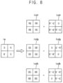
- FIG. 8 and FIG. 9 are diagrams illustrating images in a demosaicing method based on deep learning according to example embodiments. For convenience of illustration, only four pixels of the unit structure of the Bayer pattern corresponding to a red color R, a green color G and a blue color B.
- the artificial neural network 110 in FIG. 2 may simultaneously generate a red color difference image Icdr for restoring a demosaiced red image Idr, a green color difference image Icdg for restoring a demosaiced green image Idg and a blue color difference image Icdb for restoring a demosaiced blue image Idb.
- the color difference pixel value RR corresponding to a red pixel value R of the input mosaic image Im may have a value of zero.
- the color difference pixel value RG corresponding to a green pixel value G of the input mosaic image Im may have a value corresponding to a difference R′ ⁇ G′ between a red component R′ and a green component G′.
- the color difference pixel value RB corresponding to a blue pixel value B of the input mosaic image Im may have a value corresponding to a difference R′ ⁇ B′ between a red component R′ and a blue component B′.
- GR corresponding to a red pixel value R of the input mosaic image Im may have a value corresponding to a difference G′ ⁇ R′ between a green component G′ and a red component R′.
- the color difference pixel value GG corresponding to a green pixel value G of the input mosaic image Im may have a value of zero.
- the color difference pixel value GB corresponding to a blue pixel value B of the input mosaic image Im may have a value corresponding to a difference G′ ⁇ B′ between a green component G′ and a blue component B′.
- the color difference pixel value BR corresponding to a red pixel value R of the input mosaic image Im may have a value corresponding to a difference B′ ⁇ R′ between a blue component B′ and a red component R′.
- the color difference pixel value BG corresponding to a green pixel value G of the input mosaic image Im may have a value corresponding to a difference B′ ⁇ G′ between a blue component B′ and a green component G′.
- the color difference pixel value BB corresponding to a blue pixel value B of the input mosaic image Im may have a value of zero.
- the adder circuit 120 in FIG. 2 may generate the demosaiced red image Idr, the demosaiced green image Idg and the demosaiced blue image Idb by summing, pixel by pixel, each of the red color difference image Icdr, green color difference image Icdg and the blue color difference image Icdb and the input mosaic image Im.
- the adder circuit 120 may generate each color pixel value of the demosaiced color images Idr, Idg and Idb by summing each color difference pixel value of the color difference images Icdr, Icdg and Icdb and each color pixel value of the input mosaic image Im.
- the adder circuit 120 may generate each color pixel value of the demosaiced color images Idr, Idg and Idb by performing the pixel-wise addition of the input mosaic image Im and each of the color difference images Icdr, Icdg and Icdb.
- FIG. 10 and FIG. 11 are diagrams for describing examples of a deep learning neural network structure that is driven by a machine learning device according to example embodiments.
- a general neural network may include an input layer IL, a plurality of hidden layers HL 1 , HL 2 , . . . , HLn and an output layer OL.
- the input layer IL may include i input nodes x 1 , x 2 , . . . , xi, where i is a natural number.
- Input data (e.g., vector input data) IDAT with a length i may be input to the input nodes x 1 , x 2 , . . . , xi such that each element of the input data IDAT is input to a respective one of the input nodes x 1 , x 2 , . . . , xi.
- the plurality of hidden layers HL 1 , HL 2 , . . . , HLn may include n hidden layers, where n is a natural number, and may include a plurality of hidden nodes h 1 1 , h 1 2 , h 1 3 , h 1 m , h 2 1 , h 2 2 , h 1 1 , h 1 2 , h 1 3 , h 1 m , h n 1 , h n 2 , h n 3 , . . . , h n m .
- the hidden layer HL 1 may include m hidden nodes h 1 1 , h 1 2 , h 1 3 , . . . , h n m .
- the hidden layer HL 1 may include m hidden nodes h 1 1 , h 1 2 , h 1 3 , . .
- the hidden layer HL 2 may include m hidden nodes h 2 1 , h 2 2, h 2 3 , . . . , h 2 m
- the hidden layer HLn may include m hidden nodes h n 1 , h n 2 , h n 3 , . . . , h n m , where m is a natural number.
- the number of hidden nodes may be determined variously per hidden layer.
- the output layer OL may include j output nodes y 1 , y 2 , . . . , y j to generate output data ODAT corresponding to the input data IDAT where j is a natural number.
- a structure of the neural network illustrated in FIG. 10 may be represented by information on branches (or connections) between nodes illustrated as lines, and a weighted value assigned to each branch. Nodes within one layer may not be connected to one another, but nodes of different layers may be fully or partially connected to one another.
- Each node may receive an output of a previous node (e.g., the node x 1 ), may perform a computing operation, computation or calculation on the received output, and may output a result of the computing operation, computation or calculation as an output to a next node (e.g., the node h 2 1 ).
- Each node may calculate a value to be output by applying the input to a specific function, e.g., a nonlinear function.
- the structure of the neural network may be set in advance, and the weighted values for the connections between the nodes are set appropriately using data having an already known answer of which class the data belongs to.
- the data with the already known answer is referred to as “training data,” and a process of determining the weighted value is referred to as “training.”
- the neural network “learns” during the training process.
- a group of an independently trainable structure and the weighted value is referred to as a “model,” and a process of predicting, by the model with the determined weighted value, which class the input data belongs to, and then outputting the predicted value, is referred to as a “testing” process.
- the general neural network illustrated in FIG. 10 may not be suitable for handling input image data (or input sound data) because each node (e.g., the node h 1 1 ) is connected to all nodes of a previous layer (e.g., the nodes x 1 , x 2 , . . . , x i included in the layer IL) and then the number of weighted values drastically increases as the size of the input image data increases.
- a convolutional neural network which is implemented by combining the filtering technique with the general neural network, has been researched such that two-dimensional image data (e.g., the input image data) is efficiently trained by the convolutional neural network.
- a convolutional neural network may include a plurality of layers CONV 1 , RELU 1 , CONV 2 , RELU 2 , POOL 1 , CONV 3 , RELU 3 , CONV 4 , RELU 4 , POOL 2 , CONV 5 , RELU 5 , CONV 6 , RELU 6 , POOL 3 , and so on.
- each layer of the convolutional neural network may have three dimensions of width, height, and depth, and thus data that is input to each layer may be volume data having three dimensions of width, height, and depth.
- data that is input to each layer may be volume data having three dimensions of width, height, and depth.
- an input image in FIG. 11 has a size of 32 width units (e.g., 32 pixels) and 32 height units (e.g., 32 pixels) and three color channels R, G and B
- input data IDAT corresponding to the input image may have a size of 32 ⁇ 32 ⁇ 3.
- the input data IDAT may be referred to as input volume data or input activation volume.
- Each of convolutional layers CONV 1 , CONV 2 , CONV 3 , CONV 4 , CONV 5 and CONV 6 may perform a convolutional operation on input volume data.
- the convolutional operation represents an operation in which image data is processed based on a mask with weighted values and an output value is obtained by multiplying input values by the weighted values and adding up the total multiplied values.
- the mask may be referred to as a filter, window, or kernel.
- parameters of each convolutional layer may consist of or include a set of learnable filters. Every filter may be spatially small (along width and height), but may extend through the full depth of an input volume. For example, during the forward pass, each filter may be slid (more precisely, convolved) across the width and height of the input volume, and dot products may be computed between the entries of the filter and the input at any position. As the filter is slid over the width and height of the input volume, a two-dimensional activation map that gives the responses of that filter at every spatial position may be generated. As a result, an output volume may be generated by stacking these activation maps along the depth dimension.
- output volume data of the convolutional layer CONV 1 may have a size of 32 ⁇ 32 ⁇ 12 (e.g., a depth of volume data increases).
- output volume data of the RELU layer RELU 1 may have a size of 32 ⁇ 32 ⁇ 12 (e.g., a size of volume data is maintained).
- Each of pooling layers POOL 1 , POOL 2 and POOL 3 may perform a down-sampling operation on input volume data along spatial dimensions of width and height. For example, four input values arranged in a 2 ⁇ 2 matrix formation may be converted into one output value based on a 2 ⁇ 2 filter. For example, a maximum value of four input values arranged in a 2 ⁇ 2 matrix formation may be selected based on 2 ⁇ 2 maximum pooling, or an average value of four input values arranged in a 2 ⁇ 2 matrix formation may be obtained based on 2 ⁇ 2 average pooling.
- output volume data of the pooling layer POOL 1 may have a size of 16 ⁇ 16 ⁇ 12 (e.g., width and height of volume data decreases, and a depth of volume data is maintained).
- one convolutional layer e.g., CONV 1
- one RELU layer e.g., RELU 1
- CONV 1 convolutional layer
- RELU 1 RELU layer
- Pairs of the CONV/RELU layers may be repeatedly arranged in the convolutional neural network.
- the pooling layer may be periodically inserted in the convolutional neural network. As a result an image spatial size may be reduced and an image characteristic may be extracted.
- the types and number of layers included in the convolutional neural network are not necessarily limited to the example described above with reference to FIG. 11 and may be changed or vary according to one or more other exemplary embodiments.
- the convolutional neural network may further include other layers such as a softmax layer for converting score values corresponding to predicted results into probability values, a bias adding layer for adding at least one bias, or the like.
- FIG. 12 is a diagram illustrating an example of a node included in a neural network
- FIG. 12 illustrates an example node operation performed by a node ND in a neural network.
- the node ND may multiply the n inputs a 1 ⁇ an and corresponding n weights w 1 ⁇ wn, respectively, may sum n values obtained by the multiplication, may add an offset “b” to a summed value, and may generate one output value by applying a value to which the offset “b” is added to a specific function “ ⁇ ”.
- the learning operation may be performed based on the training data to update all nodes in the neural network.
- FIG. 13 is a flow chart illustrating an example embodiment of training an artificial neural network in a demosaicing method based on deep learning according to example embodiments.
- FIG. 14 is a diagram illustrating images in training the artificial neural network of FIG. 13 . For convenience of illustration and description, only pixels corresponding to one unit structure of the Bayer pattern are shown in FIG. 14 .
- a plurality of original color images corresponding to the plurality of colors may be provided (S 110 ).
- the plurality of original color images may include an original red image Ir, an original green image Ig and an original blue image Ib.
- the original red image Ir, the original green image Ig and the original blue image Ib may be full color images or demosaiced images.
- the original red image Ir may include four red pixel values R 1 ⁇ R 4 corresponding to four pixels
- the original green image Ig may include four green pixel values G 1 ⁇ G 4 corresponding to the four pixels
- the original blue image Ib may include four blue pixel values B 1 ⁇ B 4 corresponding to the four pixels.
- each of the original red image Ir, the original green image Ig and the original blue image Ib may include n*m pixels (n, m are positive integers) and each pixel in one image one-to-one corresponds to each pixel in another image by the same pixel position.
- the training mosaic image may be generated based on the plurality of original color images (S 120 ).
- each pixel value of the training mosaic image Itm may be determined by extracting each pixel value from one of the original red image Ir, the original green image Ig and the original blue image Ib based on the same pixel position. For example, the second red pixel value R 2 of the original red image Ir, the first green pixel value G 1 and the fourth green pixel value G 4 of the original green image Ig, and the third blue pixel value B 3 of the original blue image Ib may be extracted as the color pixel values of the training mosaic image Itm.
- the plurality of training color difference images may be generated based on the training mosaic image using the artificial neural network (S 130 ).
- a red channel image Icr, a green channel image Icg and a blue channel image Icb including only the corresponding color pixel values may be generated based on the training mosaic image Itm.
- the red channel image Icr, the green channel image Icg, and the blue channel image Icb may be provided as input of an artificial neural network to generate a training red color difference image Itcdr, a training green color difference image Itcdg, and a training blue color difference image Itcdb.
- the color difference pixel values of the training red color difference image Itcdr, the training green color difference image Itcdg, and the training blue color difference image Itcdb may correspond to differences of the red component R′, the green component G′ and the blue component B′ as described with reference to FIG. 8 .
- Parameters of the artificial neural network may be updated based on the plurality of original color images and the plurality of training color difference images (S 140 ). The updating of the parameters will be described with reference to FIG. 15 and FIG. 16 .
- FIG. 13 illustrates the training process using one original image set of the plurality of original color images.
- training of the artificial neural network as illustrated in FIG. 13 is performed repeatedly based on a huge number of original image sets.
- the performance or the accuracy of the finally trained artificial neural network may depend on the number of the original image sets used in training, the complexity of the artificial neural network, etc.
- FIG. 15 is a flow chart illustrating an example embodiment of updating parameters of an artificial neural network in a demosaicing method based on deep learning according to example embodiments.
- FIG. 16 is a diagram for describing the parameter updating of FIG. 15 .
- a plurality of original color difference images corresponding to the plurality of colors may be generated based on the plurality original color images (S 141 ).
- the plurality of original color images may be demosaiced images corresponding to a plurality of colors which are open in public.
- Ground truth images for supervised learning of an artificial neural network may be generated using the plurality of original color images.
- an original red color difference image Ior, an original green color difference image log and an original blue color difference image Iob may be generated by calculating differences between the pixel values of the original red image Ir, the original green image Ig and the original blue image Ib.
- the color difference pixel values of the original red color difference image Ior may be obtained by subtracting the color pixel values G 1 , R 2 , B 3 and G 4 of the training mosaic image Itm in FIG. 14 from the red pixel values R 1 , R 2 , R 3 and R 4 of the original red image Ir, respectively.
- the color difference pixel values of the original green color difference image Iob may be obtained by subtracting the color pixel values G 1 , R 2 , B 3 and G 4 of the training mosaic image Itm in FIG. 14 from the green pixel values G 1 , G 2 , G 3 and G 4 of the original green image Ig, respectively.
- the color difference pixel values of the original blue color difference image Iob may be obtained by subtracting the color pixel values G 1 , R 2 , B 3 and G 4 of the training mosaic image Itm in FIG. 14 from the blue pixel values B 1 , B 2 , B 3 and B 4 of the original green image Ig, respectively.
- the plurality of original color difference images and the plurality of training color difference images may be compared (S 142 ).
- FIG. 16 illustrates the training red color difference image Itcdr, the training green color difference image Itcdg and the training blue color difference image Itcdb that are generated from the artificial neural network.
- the training red color difference image Itcdr may be compared with the original red color difference image Ior.
- the training green color difference image Itcdg may be compared with the original green color difference image Iog.
- the training blue color difference image Itcdb may be compared with the original blue color difference image Iob.
- the original red color difference image Ior, the original green color difference image Iog and the original blue color difference image Iob, which are generated using the plurality of original color images Ir, Ig and Ib, correspond to ground truth images.
- the learning degree of the artificial neural network may be estimated through the supervised learning by comparing the training color difference images Itcdr, Itcdg and Itcdb, which are generated from the artificial neural network, with the ground truth images Ior, Iog and Iob.
- the parameters of the artificial neural network may be updated based on a result of the comparing.
- a loss value may be generated based on values obtained by subtracting, pixel by pixel, the color difference pixel values of the plurality of training color difference images Itcdr, Itcdg and Itcdb from the color difference pixel values of the plurality of original color difference images Ior, Iog and Iob (S 143 ).
- the parameters of the artificial neural network may be adjusted such that the loss value may be minimized (S 144 ).
- a loss function for generating the loss value may be determined properly for quantification of the error or the difference between the ground truth and the output of the artificial neural network.
- the loss function may include the L1 loss function, the L2 loss function, the peak signal to noise ratio (PSNR) function, the structural similarity (SSIM) function, etc., which are well known to those skilled in the art.
- the trained artificial neural network may be provided by repeatedly performing the processes of FIG. 13 and FIG. 15 and gradually updating the parameters such as weight values of the artificial neural network in the direction to reduce the loss value, until a learning completion condition is satisfied, for example, until the loss value is decreased to be smaller than a predetermined reference value.
- an artificial neural network having an encoder-decoder structure is described with reference to FIG. 17 . It will be understood that example embodiments are not limited to the encoder-decoder structure.
- the artificial neural network for the demosaicing method according to example embodiments may have various structures.
- FIG. 17 is a block diagram illustrating a structure of an artificial neural network for a demosaicing method based on deep learning according to example embodiments.
- an artificial neural network for a demosaicing method may be implemented as a convolutional neural network (CNN) having an encoder-decoder structure.
- CNN convolutional neural network
- a CNN or an artificial neural network 300 may include a plurality of encoders ENC 1 ⁇ ENCk and a plurality of decoders DEC 1 ⁇ DECk, which are cascade-connected.
- the artificial neural network 300 may be trained or learned to generate color difference images based on mosaic images or mosaiced images.
- the artificial neural network 300 may be trained to simultaneously generate a plurality of color difference images (e.g., a red color difference image, a green color difference image and a blue color difference image) by performing a nonlinear operation on color pixel values (e.g., red pixel values, green pixel values and blue pixel values) of the input mosaic image.
- the output layer of the artificial neural network 300 may include a plurality of channels to output a plurality of color channel images.
- the artificial neural network 300 may include three encoders ENC 1 , ENC 2 and ENC 3 configured to sequentially perform down-sampling based on an input mosaic image and three decoders DEC 1 , DEC 2 and DEC 3 configured to sequentially perform up-sampling.
- the encoders ENC 1 , ENC 2 and ENC 3 may include at least one convolution layer CONV having a predetermined kernel size (e.g., 3 ⁇ 3 size) and stride sizes.
- the decoders DEC 1 , DEC 2 and DEC 3 may include a de-convolution layer and a convolution layer. At least one of the encoders ENC 1 , ENC 2 and ENC 3 and the decoders DEC 1 , DEC 2 and DEC 3 may include a summing layer to perform an elementary-wise sum.
- the de-convolution layer and the convolution layer may include a rectified linear layer.
- the encoders ENC 1 , ENC 2 and ENC 3 may sequentially perform down-sampling and training of residual components based on the input mosaic image or the training mosaic image to generate encoded image maps.
- the decoders DEC 1 , DEC 2 and DEC 3 may sequentially perform up-sampling and restoring of resolution based on the encoded image maps to generate the color difference images as described above.
- the artificial neural network 300 is based on deep learning to restore RGB color difference images from an RGB mosaic image.
- the pixel values are split per red, green, and blue to generate different color channel signals that are input to the artificial neural network 300 .
- the residual components may be trained through the encoders and the resolution may be restored through the decoders.
- the high-frequency components of the input signal may be reserved through skip-connection. As such, the artificial neural network 300 may generate the three-channel color difference images that are restored finally.
- Demosaicing is digital image processing to generate full color images (e.g., demosaiced images) from an imperfect color image (e.g., a mosaic image or a CFA image).
- the full color image may be obtained using a plurality of image sensors corresponding to different colors, but such schemes increase costs and require spectral band pass filter having a form of a beam splitter.
- one color component per each pixel may be obtained using an image sensor including a color filter array (CFA) and missing color components may be obtained through interpolation methods.
- CFA color filter array
- the demosaicing method and the demosaicing device may reduce image artifact and enhance image quality.
- Image quality may be enhanced by generating the color difference images using the artificial neural network having enhanced nonlinearity and by restoring the demosaiced color images simultaneously based on the color difference images.
- FIG. 18 and FIG. 19 are diagrams illustrating effects of a demosaicing method based on deep learning according to example embodiments.
- FIG. 18 illustrates demosaiced images IMGc generated by a conventional interpolating method and demosaiced images IMGp generated by a demosaicing method according to example embodiments.
- FIG. 19 illustrates estimated values VLc corresponding to the demosaiced image generated by the conventional interpolating method and estimated values VLp corresponding to the demosaiced image generated by the demosaicing method according to example embodiments, through two estimating methods of PSNR and SSIM.
- the image artifact may be reduced and the image quality may be enhanced through the demosaicing method according to example embodiments.
- FIG. 20 is a block diagram illustrating a system performing a demosaicing method based on deep learning according to example embodiments.
- a system 1000 may include camera module 1114 (CAM), a transceiver 1140 (TRX), a control unit 1160 and a user interface 1150 .
- CAM camera module
- TRX transceiver
- control unit 1160 control unit
- user interface 1150 user interface
- the camera module 1114 may include a camera and/or an image sensor to capture and provide images.
- the camera module 1114 may include a plurality of cameras to capture a plurality of input images to be merged.
- the camera module 1114 may provide a plurality of input images to be merged where the plurality of input images are captured by a single camera.
- the transceiver 1140 may provide connectivity through wired or wireless links to other networks such as an internet, a cellular network, etc.
- the user interface 1150 may include input devices 1152 (KPD) such as a keyboard, a keypad, etc. and a display device 1112 (DSP) to display images.
- KPD input devices
- DSP display device 1112
- a virtual keypad or keyboard may be integrated into the display device 1112 with a touch screen/sensor or the like.
- the control unit 1116 may include a general purpose processor 1161 (PRC), a hardware device 1162 (HW), a firmware device 1163 (FW), a memory 1164 (MEM), a digital signal processor 1166 (DSP), a graphics engine 1167 (GENG), and a bus 1177 .
- the memory 1164 may store the trained artificial neural network 110 described herein, and the general purpose processor 1161 and/or the digital signal processor 1166 may execute the trained artificial neural network 110 described herein.
- the control unit 1160 may perform the demosaicing method based on deep learning according to example embodiments. In other words, the control unit 1160 may be configured to perform functions of the demosaicing device as described above.
- Example embodiments may be implemented as hardware, software, a firmware, or a combination thereof.
- the demosaicing method based on deep learning may be performed by the digital signal processor 1166 .
- the demosaicing device as described may include or may be included in the digital signal processor 1166 .
- At least a portion of the methods according to example embodiments may be performed by program instructions that are executed by a processing device.
- the program instructions may be stored in the memory 1164 as software 1165 (SW), and the program instructions may be executed by the general purpose processor 1161 and/or the digital signal processor 1166 .
- SW software 1165
- the general purpose processor 1161 may retrieve or fetch the program instructions from an internal register, an internal cache, or the memory 1164 and decode and execute the instructions. During or after execution of the program instructions, the general purpose processor 1161 may write one or more results (which may be intermediate or final results) of the program instructions to the internal register, internal cache, or the memory 1164 .
- the system 1000 may be a computer system taking any suitable physical form.
- the system 1000 may be an embedded computer system, a system-on-chip (SOC), a single-board computer system (SBC) such as a computer-on-module (COM) or system-on-module (SOM), a desktop computer system, a laptop or notebook computer system, an interactive kiosk, a mainframe, a mesh of computer systems, a mobile telephone, a personal digital assistant (PDA), a server, a tablet computer system, or a combination of two or more of these.
- SOC system-on-chip
- SBC single-board computer system
- COM computer-on-module
- SOM system-on-module
- desktop computer system a laptop or notebook computer system
- an interactive kiosk a mainframe, a mesh of computer systems
- a mobile telephone a personal digital assistant (PDA), a server, a tablet computer system, or a combination of two or more of these.
- PDA personal digital assistant
- the program instruction for implementing methods according to example embodiments may be stored in a computer-readable non-transitory storage medium or media.
- the computer-readable non-transitory storage medium may include one or more semiconductor-based or other integrated circuits (ICs) such as field-programmable gate arrays (FPGAs) or application-specific ICs (ASICs), hard disk drives (HDDs), hybrid hard drives (HHDs), optical discs, optical disc drives (ODDs), magneto-optical discs, magneto-optical drives, floppy diskettes, floppy disk drives (FDDs), magnetic tapes, solid-state drives (SSDs), RAM-drives, SECURE DIGITAL cards or drives, any other suitable computer-readable non-transitory storage media, or any suitable combination of two or more of these, where appropriate.
- ICs such as field-programmable gate arrays (FPGAs) or application-specific ICs (ASICs
- HDDs hard disk drives
- HHDs hybrid hard drives
- ODDs optical disc drives
- magneto-optical discs magneto-optical drives
- FDDs floppy diskettes
- FDDs
- FIG. 21 is a block diagram illustrating an example embodiment of an interface employable in the system of FIG. 20 according to example embodiments.
- a computing system 2100 may be implemented by a data processing device that uses or supports a mobile industry processor interface (MIPI) interface.
- the computing system 2100 may include an application processor 2110 , a three-dimensional image sensor 2140 such as a time-of-flight (ToF) sensor, a display device 2150 , etc.
- a CSI host 2112 of the application processor 2110 may perform a serial communication with a CSI device 2141 of the three-dimensional image sensor 2140 via a camera serial interface (CSI).
- the CSI host 2112 may include a deserializer (DES), and the CSI device 2141 may include a serializer (SER).
- a DSI host 2111 of the application processor 2110 may perform a serial communication with a DSI device 2151 of the display device 2150 via a display serial interface (DSI).
- DSI display serial interface
- the DSI host 2111 may include a serializer (SER), and the DSI device 2151 may include a deserializer (DES).
- the computing system 2100 may further include a radio frequency chip 2160 (RF chip) performing a communication with the application processor 2110 .
- RF chip radio frequency chip
- a physical layer (PHY) 2113 of the computing system 2100 and a physical layer 2161 (PHY) of the radio frequency chip 2160 may perform data communications based on a MIPI DigRF.
- the application processor 2110 may further include a DigRF MASTER 2114 that controls the data communications of the physical layer 2161 .
- the computing system 2100 may further include a global positioning system 2120 (GPS), a storage 2170 , a MIC 2180 , a DRAM device 2185 , and a speaker 2190 .
- GPS global positioning system
- the computing system 2100 may perform communications using an ultra-wideband 2210 (UWB), a wireless local area network 2220 (WLAN), a worldwide interoperability for microwave access 2130 (WIMAX), etc.
- UWB ultra-wideband 2210
- WLAN wireless local area network
- WIMAX worldwide interoperability for microwave access 2130
- the structure and the interface of the computing system 2100 are not limited thereto.
- the demosaicing method and the demosaicing device may reduce image artifact and enhance image quality.
- Image quality may be enhanced by generating the color difference images using the artificial neural network having enhanced nonlinearity and by restoring the demosaiced color images simultaneously based on the color difference images.
- embodiments of the present disclosure may be embodied as a system, method, computer program product, or a computer program product embodied in one or more computer readable medium(s) having computer readable program code embodied thereon.
- the computer readable program code may be provided to a processor of a general purpose computer, special purpose computer, or other programmable data processing apparatus.
- the computer readable medium may be a computer readable signal medium or a computer readable storage medium.
- the computer readable storage medium may be any tangible medium that can contain, or store a program for use by or in connection with an instruction execution system, apparatus, or device.
- inventive concept(s) described herein may be applied to any electronic devices and systems requiring image processing.
- inventive concept(s) described herein may be applied to systems such as a computer, a mobile phone, a smart phone, a personal digital assistant (PDA), a portable multimedia player (PMP), a digital camera, a camcorder, a personal computer (PC), a server computer, a workstation, a laptop computer, a digital TV, a set-top box, a portable game console, a navigation system, a wearable device, an internet of things (IoT) device, an internet of everything (IoE) device, an e-book, a virtual reality (VR) device, an augmented reality (AR) device, a vehicle navigation device, a video phone, a monitoring system, an auto focusing system, a tracking system, and a motion detection system, etc.
- IoT internet of things
- IoE internet of everything
- e-book a virtual reality (VR) device
- AR augmented reality
Landscapes
- Engineering & Computer Science (AREA)
- Theoretical Computer Science (AREA)
- Physics & Mathematics (AREA)
- General Physics & Mathematics (AREA)
- Artificial Intelligence (AREA)
- Evolutionary Computation (AREA)
- Data Mining & Analysis (AREA)
- Molecular Biology (AREA)
- Biophysics (AREA)
- Computational Linguistics (AREA)
- Life Sciences & Earth Sciences (AREA)
- Health & Medical Sciences (AREA)
- General Health & Medical Sciences (AREA)
- Biomedical Technology (AREA)
- Computing Systems (AREA)
- General Engineering & Computer Science (AREA)
- Mathematical Physics (AREA)
- Software Systems (AREA)
- Computer Vision & Pattern Recognition (AREA)
- Image Processing (AREA)
- Image Analysis (AREA)
Abstract
Description
Claims (20)
Applications Claiming Priority (2)
| Application Number | Priority Date | Filing Date | Title |
|---|---|---|---|
| KR1020200138500A KR102797187B1 (en) | 2020-10-23 | 2020-10-23 | Demosaicing method and demosaicing device based on deep learning |
| KR10-2020-0138500 | 2020-10-23 |
Publications (2)
| Publication Number | Publication Date |
|---|---|
| US20220130012A1 US20220130012A1 (en) | 2022-04-28 |
| US12136183B2 true US12136183B2 (en) | 2024-11-05 |
Family
ID=81257354
Family Applications (1)
| Application Number | Title | Priority Date | Filing Date |
|---|---|---|---|
| US17/335,970 Active 2042-10-20 US12136183B2 (en) | 2020-10-23 | 2021-06-01 | Demosaicing method and demosaicing device |
Country Status (3)
| Country | Link |
|---|---|
| US (1) | US12136183B2 (en) |
| KR (1) | KR102797187B1 (en) |
| CN (1) | CN114494009A (en) |
Families Citing this family (6)
| Publication number | Priority date | Publication date | Assignee | Title |
|---|---|---|---|---|
| US11676248B2 (en) * | 2020-01-23 | 2023-06-13 | Baidu Usa Llc | Deep residual network for color filter array image denoising |
| FR3135155B1 (en) * | 2022-04-27 | 2024-04-19 | Airbus Defence & Space Sas | Method for non-local demosaicing of an image and associated device |
| US20250166123A1 (en) * | 2023-11-17 | 2025-05-22 | Samsung Electronics Co., Ltd. | Examining joint demosaicing and denoising for single-bayer, quad-bayer, and nona-bayer patterns |
| US20250200720A1 (en) * | 2023-12-15 | 2025-06-19 | Samsung Electronics Co., Ltd. | Detail preserving denoiser for short exposure images |
| CN119130788A (en) * | 2024-09-20 | 2024-12-13 | 长春理工大学 | A color polarization image demosaicing and image fusion method based on deep learning |
| CN119360052B (en) * | 2024-10-25 | 2025-11-04 | 长光卫星技术股份有限公司 | Automated detection method for mosaic color difference in large-area remote sensing images |
Citations (6)
| Publication number | Priority date | Publication date | Assignee | Title |
|---|---|---|---|---|
| KR100565429B1 (en) | 2003-11-27 | 2006-03-30 | 한국전자통신연구원 | Method and apparatus for recovering lost color values in color filter array |
| US7830426B2 (en) | 2005-12-29 | 2010-11-09 | Micron Technology, Inc. | Method and apparatus providing color interpolation in color filter arrays using edge detection and correction terms |
| KR101882739B1 (en) | 2017-07-18 | 2018-07-27 | 인천대학교 산학협력단 | Images Upsampling and Pattern Assignment Apparatus and Method thereof |
| US20190385325A1 (en) | 2017-02-22 | 2019-12-19 | Korea Advanced Institute Of Science And Technology | Apparatus and method for depth estimation based on thermal image, and neural network learning method therefof |
| JP6644877B2 (en) | 2016-04-20 | 2020-02-12 | 株式会社日立国際電気 | Image processing device |
| KR102137047B1 (en) | 2019-06-26 | 2020-07-24 | 인천대학교 산학협력단 | Demosaicking method based on back propagation neural network |
-
2020
- 2020-10-23 KR KR1020200138500A patent/KR102797187B1/en active Active
-
2021
- 2021-06-01 US US17/335,970 patent/US12136183B2/en active Active
- 2021-09-17 CN CN202111091277.6A patent/CN114494009A/en active Pending
Patent Citations (6)
| Publication number | Priority date | Publication date | Assignee | Title |
|---|---|---|---|---|
| KR100565429B1 (en) | 2003-11-27 | 2006-03-30 | 한국전자통신연구원 | Method and apparatus for recovering lost color values in color filter array |
| US7830426B2 (en) | 2005-12-29 | 2010-11-09 | Micron Technology, Inc. | Method and apparatus providing color interpolation in color filter arrays using edge detection and correction terms |
| JP6644877B2 (en) | 2016-04-20 | 2020-02-12 | 株式会社日立国際電気 | Image processing device |
| US20190385325A1 (en) | 2017-02-22 | 2019-12-19 | Korea Advanced Institute Of Science And Technology | Apparatus and method for depth estimation based on thermal image, and neural network learning method therefof |
| KR101882739B1 (en) | 2017-07-18 | 2018-07-27 | 인천대학교 산학협력단 | Images Upsampling and Pattern Assignment Apparatus and Method thereof |
| KR102137047B1 (en) | 2019-06-26 | 2020-07-24 | 인천대학교 산학협력단 | Demosaicking method based on back propagation neural network |
Non-Patent Citations (3)
| Title |
|---|
| Michael Garbi et al., "Deep Joint Demosaiching and Denoising," 4 pages. |
| Office Action in Korean Appln. No. 10-2020-0138500, mailed on Jul. 31, 2024, 10 pages (with English translation). |
| Soo-Chang Pei, "Effective Color Interpolation in CCD Color Filter Arrays Using Signal Correlation," IEEE Transactions on Circuits and Systems for Video Technology, Jun. 2003, 503-513, vol. 13, No. 6. |
Also Published As
| Publication number | Publication date |
|---|---|
| CN114494009A (en) | 2022-05-13 |
| KR20220054044A (en) | 2022-05-02 |
| US20220130012A1 (en) | 2022-04-28 |
| KR102797187B1 (en) | 2025-04-18 |
Similar Documents
| Publication | Publication Date | Title |
|---|---|---|
| US12136183B2 (en) | Demosaicing method and demosaicing device | |
| US11676248B2 (en) | Deep residual network for color filter array image denoising | |
| CN111127336A (en) | An Image Signal Processing Method Based on Adaptive Selection Module | |
| CN113850741B (en) | Image noise reduction method and device, electronic equipment and storage medium | |
| CN114418882B (en) | Processing method, training device, electronic equipment and medium | |
| CN110555808A (en) | Image processing method, device, equipment and machine-readable storage medium | |
| CN101512600A (en) | Sparse integral image descriptors for motion analysis | |
| JP2023537864A (en) | Systems and methods for performing image enhancement using neural networks implemented by channel-constrained hardware accelerators | |
| CN115641260A (en) | Image processing method, module, device, storage medium and program product | |
| US11861807B2 (en) | Method of color decomposition and method of demosaicing images based on deep learning using the same | |
| CN113674149B (en) | A new super-resolution reconstruction method based on convolutional neural network | |
| CN115423885B (en) | Image processing methods, apparatus and electronic devices | |
| CN115311149A (en) | Image denoising method, model, computer-readable storage medium and terminal device | |
| US12354243B2 (en) | Image denoising method, device, and computer-readable medium using U-net | |
| JP2025517801A (en) | Image noise reduction processing method, apparatus, device, storage medium and program product | |
| Guo et al. | How to best combine demosaicing and denoising? | |
| EP4386656B1 (en) | Demosaicing method and demosaicing device | |
| CN117217987A (en) | Image processing methods, devices, equipment and systems | |
| US20250078201A1 (en) | Coordinate-based self-supervision for burst demosaicing and denoising | |
| CN115689862A (en) | Video processing method and device, electronic equipment and non-transitory readable storage medium | |
| CN121304464B (en) | Image processing method and device and computer equipment | |
| CN121599860B (en) | Extreme Low-Light Image Restoration Method and Apparatus | |
| CN121280241A (en) | Sequence image restoration method based on non-local feature fusion | |
| CN117115593A (en) | Model training method, image processing method and device | |
| KR20250121910A (en) | Method and apparatus for image restoration |
Legal Events
| Date | Code | Title | Description |
|---|---|---|---|
| AS | Assignment |
Owner name: SAMSUNG ELECTRONICS CO., LTD., KOREA, REPUBLIC OF Free format text: ASSIGNMENT OF ASSIGNORS INTEREST;ASSIGNORS:PARK, SOYOUN;JUNG, BYUNGWOOK;REEL/FRAME:056406/0281 Effective date: 20210405 |
|
| FEPP | Fee payment procedure |
Free format text: ENTITY STATUS SET TO UNDISCOUNTED (ORIGINAL EVENT CODE: BIG.); ENTITY STATUS OF PATENT OWNER: LARGE ENTITY |
|
| STPP | Information on status: patent application and granting procedure in general |
Free format text: DOCKETED NEW CASE - READY FOR EXAMINATION |
|
| STPP | Information on status: patent application and granting procedure in general |
Free format text: NON FINAL ACTION MAILED |
|
| STPP | Information on status: patent application and granting procedure in general |
Free format text: RESPONSE TO NON-FINAL OFFICE ACTION ENTERED AND FORWARDED TO EXAMINER |
|
| STPP | Information on status: patent application and granting procedure in general |
Free format text: FINAL REJECTION MAILED |
|
| STPP | Information on status: patent application and granting procedure in general |
Free format text: RESPONSE AFTER FINAL ACTION FORWARDED TO EXAMINER |
|
| STPP | Information on status: patent application and granting procedure in general |
Free format text: ADVISORY ACTION MAILED |
|
| STPP | Information on status: patent application and granting procedure in general |
Free format text: DOCKETED NEW CASE - READY FOR EXAMINATION |
|
| STPP | Information on status: patent application and granting procedure in general |
Free format text: NOTICE OF ALLOWANCE MAILED -- APPLICATION RECEIVED IN OFFICE OF PUBLICATIONS |
|
| STPP | Information on status: patent application and granting procedure in general |
Free format text: AWAITING TC RESP., ISSUE FEE NOT PAID |
|
| STPP | Information on status: patent application and granting procedure in general |
Free format text: NOTICE OF ALLOWANCE MAILED -- APPLICATION RECEIVED IN OFFICE OF PUBLICATIONS |
|
| STPP | Information on status: patent application and granting procedure in general |
Free format text: PUBLICATIONS -- ISSUE FEE PAYMENT RECEIVED |
|
| STPP | Information on status: patent application and granting procedure in general |
Free format text: AWAITING TC RESP, ISSUE FEE PAYMENT VERIFIED |
|
| STPP | Information on status: patent application and granting procedure in general |
Free format text: PUBLICATIONS -- ISSUE FEE PAYMENT VERIFIED |
|
| STCF | Information on status: patent grant |
Free format text: PATENTED CASE |