US12134576B2 - Apparatus for processing cover window and method for processing cover window - Google Patents
Apparatus for processing cover window and method for processing cover window Download PDFInfo
- Publication number
- US12134576B2 US12134576B2 US17/661,808 US202217661808A US12134576B2 US 12134576 B2 US12134576 B2 US 12134576B2 US 202217661808 A US202217661808 A US 202217661808A US 12134576 B2 US12134576 B2 US 12134576B2
- Authority
- US
- United States
- Prior art keywords
- mold
- support
- pressurizing
- pressurizing portion
- sub
- Prior art date
- Legal status (The legal status is an assumption and is not a legal conclusion. Google has not performed a legal analysis and makes no representation as to the accuracy of the status listed.)
- Active, expires
Links
Images


Classifications
-
- B—PERFORMING OPERATIONS; TRANSPORTING
- B26—HAND CUTTING TOOLS; CUTTING; SEVERING
- B26F—PERFORATING; PUNCHING; CUTTING-OUT; STAMPING-OUT; SEVERING BY MEANS OTHER THAN CUTTING
- B26F1/00—Perforating; Punching; Cutting-out; Stamping-out; Apparatus therefor
- B26F1/38—Cutting-out; Stamping-out
- B26F1/44—Cutters therefor; Dies therefor
-
- B—PERFORMING OPERATIONS; TRANSPORTING
- B29—WORKING OF PLASTICS; WORKING OF SUBSTANCES IN A PLASTIC STATE IN GENERAL
- B29C—SHAPING OR JOINING OF PLASTICS; SHAPING OF MATERIAL IN A PLASTIC STATE, NOT OTHERWISE PROVIDED FOR; AFTER-TREATMENT OF THE SHAPED PRODUCTS, e.g. REPAIRING
- B29C43/00—Compression moulding, i.e. applying external pressure to flow the moulding material; Apparatus therefor
- B29C43/02—Compression moulding, i.e. applying external pressure to flow the moulding material; Apparatus therefor of articles of definite length, i.e. discrete articles
- B29C43/021—Compression moulding, i.e. applying external pressure to flow the moulding material; Apparatus therefor of articles of definite length, i.e. discrete articles characterised by the shape of the surface
-
- B—PERFORMING OPERATIONS; TRANSPORTING
- B29—WORKING OF PLASTICS; WORKING OF SUBSTANCES IN A PLASTIC STATE IN GENERAL
- B29C—SHAPING OR JOINING OF PLASTICS; SHAPING OF MATERIAL IN A PLASTIC STATE, NOT OTHERWISE PROVIDED FOR; AFTER-TREATMENT OF THE SHAPED PRODUCTS, e.g. REPAIRING
- B29C43/00—Compression moulding, i.e. applying external pressure to flow the moulding material; Apparatus therefor
- B29C43/32—Component parts, details or accessories; Auxiliary operations
- B29C43/36—Moulds for making articles of definite length, i.e. discrete articles
-
- B—PERFORMING OPERATIONS; TRANSPORTING
- B29—WORKING OF PLASTICS; WORKING OF SUBSTANCES IN A PLASTIC STATE IN GENERAL
- B29C—SHAPING OR JOINING OF PLASTICS; SHAPING OF MATERIAL IN A PLASTIC STATE, NOT OTHERWISE PROVIDED FOR; AFTER-TREATMENT OF THE SHAPED PRODUCTS, e.g. REPAIRING
- B29C43/00—Compression moulding, i.e. applying external pressure to flow the moulding material; Apparatus therefor
- B29C43/32—Component parts, details or accessories; Auxiliary operations
- B29C43/52—Heating or cooling
-
- C—CHEMISTRY; METALLURGY
- C03—GLASS; MINERAL OR SLAG WOOL
- C03B—MANUFACTURE, SHAPING, OR SUPPLEMENTARY PROCESSES
- C03B11/00—Pressing molten glass or performed glass reheated to equivalent low viscosity without blowing
- C03B11/12—Cooling, heating, or insulating the plunger, the mould, or the glass-pressing machine; cooling or heating of the glass in the mould
- C03B11/122—Heating
-
- C—CHEMISTRY; METALLURGY
- C03—GLASS; MINERAL OR SLAG WOOL
- C03B—MANUFACTURE, SHAPING, OR SUPPLEMENTARY PROCESSES
- C03B23/00—Re-forming shaped glass
- C03B23/02—Re-forming glass sheets
- C03B23/023—Re-forming glass sheets by bending
- C03B23/03—Re-forming glass sheets by bending by press-bending between shaping moulds
- C03B23/0302—Re-forming glass sheets by bending by press-bending between shaping moulds between opposing full-face shaping moulds
-
- C—CHEMISTRY; METALLURGY
- C03—GLASS; MINERAL OR SLAG WOOL
- C03B—MANUFACTURE, SHAPING, OR SUPPLEMENTARY PROCESSES
- C03B23/00—Re-forming shaped glass
- C03B23/02—Re-forming glass sheets
- C03B23/023—Re-forming glass sheets by bending
- C03B23/03—Re-forming glass sheets by bending by press-bending between shaping moulds
- C03B23/0307—Press-bending involving applying local or additional heating, cooling or insulating means
-
- B—PERFORMING OPERATIONS; TRANSPORTING
- B29—WORKING OF PLASTICS; WORKING OF SUBSTANCES IN A PLASTIC STATE IN GENERAL
- B29L—INDEXING SCHEME ASSOCIATED WITH SUBCLASS B29C, RELATING TO PARTICULAR ARTICLES
- B29L2007/00—Flat articles, e.g. films or sheets
-
- B—PERFORMING OPERATIONS; TRANSPORTING
- B29—WORKING OF PLASTICS; WORKING OF SUBSTANCES IN A PLASTIC STATE IN GENERAL
- B29L—INDEXING SCHEME ASSOCIATED WITH SUBCLASS B29C, RELATING TO PARTICULAR ARTICLES
- B29L2031/00—Other particular articles
- B29L2031/34—Electrical apparatus, e.g. sparking plugs or parts thereof
- B29L2031/3475—Displays, monitors, TV-sets, computer screens
-
- C—CHEMISTRY; METALLURGY
- C03—GLASS; MINERAL OR SLAG WOOL
- C03B—MANUFACTURE, SHAPING, OR SUPPLEMENTARY PROCESSES
- C03B2215/00—Press-moulding glass
- C03B2215/40—Product characteristics
- C03B2215/44—Flat, parallel-faced disc or plate products
-
- C—CHEMISTRY; METALLURGY
- C03—GLASS; MINERAL OR SLAG WOOL
- C03B—MANUFACTURE, SHAPING, OR SUPPLEMENTARY PROCESSES
- C03B2215/00—Press-moulding glass
- C03B2215/50—Structural details of the press-mould assembly
Definitions
- the present disclosure relates to an apparatus for processing a cover window, and more particularly, to an apparatus for processing a cover window and method for processing a cover window.
- display devices for displaying images have seen increased use in consumer electronics.
- display devices are applied to various electronic appliances such as smart phones, smart watches, digital cameras, notebook computers, navigators, and smart televisions.
- Various types of display devices such as an organic light emitting display (OLED) and a liquid crystal display (LCD) have been used.
- OLED organic light emitting display
- LCD liquid crystal display
- Some display devices may include a cover window to protect a display panel thereon.
- cover windows may be used to prevent scratches to the display panel, as well as to prevent dust, debris, or moisture from entering the electronic device.
- An object of the present disclosure is to provide an apparatus for processing a cover window and a method for processing a cover window, in which a plurality of cover windows may be processed at one time and the processed cover windows may be prevented from having a defect.
- An apparatus for processing one or more cover windows includes a first mold including a first support and a second support spaced apart from the first support; a second mold; and a third mold spaced apart from the second mold, wherein the first support and the second support are each configured to hold a processing target, and wherein the second mold includes a first pressurizing portion overlapping with the first support and having a first thickness, and a second pressurizing portion connected with the first pressurizing portion and overlapping with the first support and having a second thickness thinner than the first thickness, and wherein the third mold includes a third pressurizing portion overlapping with the second support and having a third thickness, and a fourth pressurizing portion connected with the third pressurizing portion and overlapping with the second support and having a fourth thickness thinner than the third thickness.
- An apparatus for processing one or more cover windows includes a first mold including a first support and a second support spaced apart from the first support; a second mold; and a third mold spaced apart from the second mold.
- the first support and second support are each configured to hold a processing target, and the second mold overlaps with the first support and includes a lower surface conformal with an upper surface of the first support, and the third mold overlaps with the second support and includes a lower surface conformal with an upper surface of the second support.
- a method for processing one or more cover windows includes preparing a first mold by forming a first support in the first mold and a second support spaced apart from the first support in the first mold; disposing a first processing target on the first and disposing a second processing target on the second support; disposing a second mold including a first pressurizing portion having a first thickness and a second pressurizing portion connected to the first pressurizing portion and having a second thickness thinner than the first thickness on the first processing target, and disposing a third mold including a third pressurizing portion having the first thickness and a fourth pressurizing portion connected to the third pressurizing portion having the second thickness on the second processing target; and pressurizing the second mold and the third mold toward the first mold to process the first processing target and the second processing target into the one or more cover windows.
- a plurality of cover windows may be processed at one time. Also, in the apparatus for processing a cover window and the method for processing a cover window according to one embodiment of the present disclosure, a processing target may uniformly be pressurized per area to reduce a rate processing defects of the cover windows.
- FIG. 1 is an exploded perspective view that illustrates a display device according to one embodiment of the present disclosure
- FIG. 2 is a perspective view that illustrates an apparatus for processing a cover window according to one embodiment of the present disclosure
- FIG. 3 is a schematic view that illustrates an apparatus for processing a cover window according to one embodiment of the present disclosure
- FIG. 4 is a plan view that illustrates a first mold according to one embodiment of the present disclosure
- FIG. 5 is a cross-sectional view taken along line V-V′ of FIG. 4 ;
- FIG. 6 is across-sectional view taken along line VI-VI′ of FIG. 4 :
- FIG. 7 is a plan view that illustrates a second mold and a third mold according to one embodiment of the present disclosure.
- FIG. 8 is a cross-sectional view taken along line VIII-VIII′ of FIG. 7 ;
- FIG. 9 is an enlarged view that illustrates an area Q of FIG. 8 ;
- FIG. 10 is an enlarged view that illustrates an area R of FIG. 8 ;
- FIG. 11 is a cross-sectional view taken along line XI-XI′ of FIG. 7 ;
- FIGS. 12 to 14 are schematic views that illustrate a process of processing a cover window using an apparatus for processing a cover window according to one embodiment of the present disclosure
- FIG. 15 is a schematic view that illustrates an apparatus for processing a cover window according to one embodiment of the present disclosure
- FIG. 16 is a schematic view that illustrates an apparatus for processing a cover window according to one embodiment of the present disclosure
- FIG. 17 is an enlarged view that illustrates an area S of FIG. 16 ;
- FIG. 18 is an enlarged view that illustrates an area T of FIG. 16 ;
- FIG. 19 is a schematic view that illustrates an apparatus for processing a cover window according to further one embodiment of the present disclosure.
- inventive concepts disclosed herein may be embodied in many different forms without departing from the spirit and significant characteristics of the inventive concepts.
- first,” “second,” “third” etc. may be used herein to describe various elements, components, regions, layers and/or sections, these elements, components, regions, layers and/or sections should not be limited by these terms. These terms are only used to distinguish one element, component, region, layer or section from another element, component, region, layer or section. Thus, “a first element,” “component,” “region,” “layer” or “section” discussed below could be termed a second element, component, region, layer or section without departing from the teachings herein.
- relative terms such as “lower” or “bottom” and “upper” or “top,” may be used herein to describe one element's relationship to another element as illustrated in the Figures. It will be understood that relative terms are intended to encompass different orientations of the device in addition to the orientation depicted in the Figures. For example, if the device in one of the figures is turned over, elements described as being on the “lower” side of other elements may then be oriented on “upper” sides of the other elements. The term “lower,” can therefore, encompass both an orientation of “lower” and “upper,” depending on the particular orientation of the figure.
- a plane shape of an object may refer to the shape of the object as viewed from a top-down perspective, or from another perspective as indicated by the accompanying description.
- the stated direction will include both directions on the given axis.
- the object may be bent in the +X or ⁇ X direction, as will be readily apparent through the context of the description with reference to the accompanying Figure(s).
- “About” or “approximately” as used in the following description is inclusive of the stated value and means within an acceptable range of deviation for the particular value as determined by one of ordinary skill in the art, considering the measurement in question and the error associated with measurement of the particular quantity (e.g., the limitations of the measurement system). For example, “about” can mean within one or more standard deviations, or within ⁇ 30%, 20%, 10% or 5% of the stated value.
- Example embodiments are described herein with reference to cross-sectional illustrations that are schematic illustrations of idealized embodiments. As such, variations from the shapes of the illustrations as a result, for example, of manufacturing techniques and/or tolerances, are to be expected. Thus, embodiments described herein should not be construed as limited to the particular shapes of regions as illustrated herein but are to include deviations in shapes that result, for example, from manufacturing. For example, a region illustrated or described as flat may, typically, have rough and/or nonlinear features. Moreover, sharp angles that are illustrated may be rounded. Thus, the regions illustrated in the figures are schematic in nature and their shapes are not intended to illustrate the precise shape of a region and are not intended to limit the scope of the present claims.
- FIG. 1 is an exploded perspective view that illustrates a display device according to one embodiment of the present disclosure.
- FIG. 1 illustrates a smart watch as a display device SW according to one embodiment
- the present disclosure is not necessarily limited to this example, and other electronic products such as a smartphone and a tablet PC may have the inventive concepts described herein applied to them.
- the display device SW may be a smartphone or other electronic device according to different embodiments.
- the display device SW may include a main body portion BP and a wearing portion BD.
- the main body portion BP may include a display portion DP on which an image is displayed, and a cover window CW disposed on the display portion DP.
- the display portion DP may be a screen in which various kinds of information, contents, user interfaces and the like are displayed as an image.
- the display portion DP may be positioned at the center of an upper surface of a main body 10 .
- the display portion DP may include an organic light emitting display, a liquid crystal display and the like, but is not necessarily limited thereto.
- the display portion DP may include a display area DA on which an image is displayed, and a non-display area NDA positioned near the display area DA.
- a plane shape of the display portion DP may be substantially a circular shape, but is not necessarily limited thereto.
- the display portion DP may have various shapes.
- the display portion DP may have a polygonal shape such as a rectangular shape, or an elliptical shape.
- the cover window CW may be disposed on an upper portion of the display portion DP.
- the cover window CW may protect the display portion DP, and may transmit light emitted from the display portion DP.
- the cover window CW may be substantially transparent to visible light.
- the cover window CW may include a rigid material such as glass, plastic or quartz.
- the cover window CW may overlap the display portion DP and cover an entire surface of the display portion DP.
- the cover window CW has a shape similar to that of the display portion DP on a plane, for example, when viewed from above, but its size may be greater than the display portion DP.
- the cover window CW may be protruded more outwardly than the display portion DP.
- a plane shape of the cover window CW may be the same as that of the body portion BP.
- the plane shape of the cover window CW may be substantially a circular shape, but is not necessarily limited thereto.
- the cover window CW may have various shapes, for example, a polygonal shape such as a rectangular shape, or an elliptical shape.
- the cover window CW may include a window central portion CP and a window edge portion EP disposed near the window central portion CP.
- the window central portion CP is positioned at the center of the cover window CW, and may be substantially flat.
- the window central portion CP may be an area corresponding to the display area DA of the display portion DP.
- the window central portion CP of the cover window CW may cover the entire display area DA of the display portion DP, but is not necessarily limited thereto.
- the window central portion CP of the cover window CW may cover only a portion of the display area DA of the display portion DP.
- the window edge portion EP may be disposed to surround the window central portion CP.
- the window edge portion EP may be a curved portion that is bent from the window central portion CP.
- the window edge portion EP may be bent from an edge of the window central portion CP.
- a portion of the window edge portion EP includes a curved surface that has a predetermined curvature and includes another portion that may be flat.
- a degree (or angle) of the window edge portion EP, which is bent from the window central portion CP, may be an obtuse angle, but may be a right angle or an acute angle.
- the window edge portion EP may include a curved surface having a predetermined curvature. The curvature of the window edge portion EP may be constant for each area, or may be different for each area.
- the wearing portion BD may allow fixing the main body portion BP to a wrist of a user, and may include a strap, a chain and/or a bracelet, for example.
- An apparatus 1 for processing a cover window may include a mold for processing the cover window CW, which includes the window central portion CP and the window edge portion EP partially bent or curved from the window central portion CP.
- the apparatus 1 for processing a cover window may process the cover window CW, which includes the window central portion CP and the window edge portion EP, by inserting and pressurizing processing targets (see ‘SMP 1 ’ and ‘SMP 2 ’ of FIG. 12 ).
- the apparatus 1 for pressurizing a cover window according to one embodiment of the present disclosure which is a mold capable of processing a plurality of cover windows CW at one time, will be described with reference to FIGS. 2 to 11 .
- the apparatus 1 for processing a cover window according to one embodiment may have a structure capable of processing a larger number of cover windows CW through one-time process, without necessarily being limited thereto.
- FIG. 2 is a perspective view that illustrates an apparatus for processing a cover window according to one embodiment.
- FIG. 3 is a schematic view that illustrates an apparatus for processing a cover window according to one embodiment.
- the apparatus 1 for processing a cover window may include a first mold 100 , a second mold 200 and a third mold 300 .
- the second mold 200 and the third mold 300 may be disposed on the first mold 100 .
- the second mold 200 and the third mold 300 may face each other.
- the apparatus 1 for processing a cover window according to one embodiment may further include a stage STG 1 and a pressurizing member STG 2 .
- the description of the stage STG 1 and the pressurizing member STG 2 will be described later with reference to FIGS. 12 to 14 that illustrate a processing procedure.
- the first mold 100 may include a first support 111 and a second support 112 disposed on the other side of the first support 111 in a second direction Y.
- the second mold 200 may be disposed on the first support 111 of the first mold 100 .
- the third mold 300 may be disposed on the second support 112 of the first mold 100 .
- the second mold 200 and the third mold 300 may have substantially the same structure.
- the second mold 200 and the third mold 300 are disposed to face each other in the second direction Y, but may be molds that substantially have the same structure.
- the structures of second mold 200 and the third mold 300 may be mirror images of each other.
- the first processing target may be pressurized with the second mold 200 in a third direction Z to process the cover window CW.
- the second processing target may be pressurized with the third mold 300 toward the other side in the third direction Z to process the cover window CW.
- the “processing” of a cover window CW may include deforming a processing target with a mold in order to form the processing target into the shape of the cover window CW.
- a detailed structure of the first mold 100 will be described later with reference to FIGS. 4 to 6
- a detailed structure of the second mold 200 and the third mold 300 will be described later with reference to FIGS. 7 to 11 .
- FIG. 4 is a plan view that illustrates a first mold according to one embodiment of the present disclosure.
- FIG. 5 is a cross-sectional view taken along line V-V′ of FIG. 4 .
- FIG. 6 is a cross-sectional view taken along line VI-VI′ of FIG. 4 .
- the first mold 100 may include a plurality of supports 110 , a first base portion 120 which sounds the plurality of supports 110 , and a second base portion 130 which sounds the first base portion 120 .
- the first mold 100 may be a lower mold in the apparatus 1 for processing a cover window according to one embodiment.
- a plane shape of the first mold 100 may be a rectangular shape.
- the plane shape of the first mold 100 may be a rectangular shape that includes short sides which extend in a first direction X and long sides which extend in a second direction Y, but is not necessarily limited thereto.
- the plane shape of the first mold 100 may be other polygonal shape, a circular shape, or an elliptical shape.
- the plurality of supports 110 included in the first mold 100 may include a first support 111 and a second support 112 spaced apart from the first support 111 in the second direction Y.
- the first support 111 may have a structure in which an upper surface is recessed toward the other side in the third direction Z.
- the upper surface of the first support 111 may bend in the ⁇ Z direction.
- the first support 111 may include a first support central portion 111 a and a first support edge portion 111 b disposed to surround the first support central portion 111 a.
- the first support central portion 111 a may be disposed substantially at the center of the first support 111 .
- the first support central portion 111 a may include a flat upper surface 111 au .
- a plane shape of the upper surface 111 au of the first support central portion 1 a may be, for example, a circular shape, but is not necessarily limited thereto.
- plane shape of the upper surface 111 au of the first support central portion 111 a may be an elliptical shape or other polygonal shape.
- the upper surface 111 au of the first support central portion 111 a may be positioned on the other side in the third direction Z rather than an upper surface of the first base portion 120 that will be described later.
- the upper surface 111 au of the first support central portion 111 a may be recessed from the third direction Z.
- Upper surfaces 111 bu and 111 bs of the first support edge portion 111 b may include a curved portion 111 bu connected with the upper surface 111 au of the first support central portion 111 a and disposed on an inner side, and a flat seating portion 111 bs surrounding the curved portion 111 bu .
- Processing targets (see ‘SMP 1 ’ and ‘SMP 2 ’ of FIG. 12 ) that have not been processed may be seated on the seating portion 111 bs .
- the curved portion 111 bu of the first support edge portion 111 b may have a shape which is recessed toward the other side in the third direction Z from the seating portion 111 bs to the first support central portion 111 a.
- a plane shape of the first support 111 may be a circular shape, but is not necessarily limited thereto. Various modifications may be made in the plane shape of the first support 111 depending on the design of the cover window CW to be processed.
- the first support 111 for processing a cover window CW that has a polygonal plane shape may have a polygonal plane shape
- the first support 111 for processing a cover window CW that has an elliptical plane shape may have an elliptical plane shape.
- the second support 112 may have a structure in which an upper surface thereof is recessed in the negative third direction ⁇ Z.
- the second support 112 may include a second support central portion 112 a and a second support edge portion 112 b disposed to surround the second support central portion 112 a .
- the structure of the second support 112 may substantially be the same as that of the first support 111 .
- the second support central portion 112 a may be disposed substantially at the center of the second support 112 .
- the second support central portion 112 a may include a flat upper surface 112 au .
- a plane shape of the second support central portion 112 a may substantially be the same as that of the second support 112 .
- the plane shape of the second support central portion 112 a may be a circular shape, but is not necessarily limited thereto.
- the plane shape of the second support central portion 112 a may be an elliptical shape or other polygonal shape.
- the upper surface 112 au of the second support central portion 112 a may be positioned on the other side in the third direction Z rather than an upper surface of the second base portion 130 , which will be described later.
- the upper surface 112 au of the second support central portion 112 a may be recessed from the third direction Z into the negative third direction ⁇ Z.
- the position of the second support central portion 112 a in the third direction Z may substantially be the same as that of the first support central portion 111 a in the third direction Z.
- a height of the second support central portion 112 a may substantially be the same as that of the first support central portion 111 a.
- Upper surfaces 112 bu and 112 bs of the second support edge portion 112 b may include a curved portion 112 bu connected with the upper surface 112 au of the first support central portion 112 a and disposed on an inner side, and a flat seating portion 112 bs surrounding the curved portion 112 bu .
- the curved portion 112 bu of the second support edge portion 112 b may have a shape recessed in the negative third direction ⁇ Z from the seating portion 112 bs to the second support central portion 112 a.
- a plane shape of the second support 112 may be a circular shape but is not necessarily limited thereto. Various modifications may be made in the plane shape of the support depending on the design of the cover window CW.
- the second support 112 for processing a cover window CW having a polygonal plane shape may have an polygonal plane shape
- the second support 112 for processing a cover window CW having an elliptical plane shape may have an elliptical plane shape.
- the plane shape of the second support 112 may substantially be the same as that of the first support 111 . In this case, the same plane shape in the second support 12 and the first support 111 means that the same area is also applied thereto. However, in some embodiments the plane shape of the second support 112 may be different from that of the first support 111 .
- a thickness t 1 of the first support 111 may mean a distance between the upper surface 111 au and a lower surface of the first support central portion 111 a
- a thickness t 2 of the second support 112 may mean a distance between the upper surface 112 au and a lower surface of the second support central portion 112 a
- the thickness t 1 of the first support 111 and the thickness t 2 of the second support 112 may substantially be the same as each other.
- the support 110 may be surrounded by a first base portion 120 .
- the first base portion 120 may include a first sub-base portion 121 , a second sub-base portion 122 , a third sub-base portion 123 , a first exhaust portion 124 , a second exhaust portion 125 , a third exhaust portion 126 , a fourth exhaust portion 127 and a fifth exhaust portion 128 .
- the first sub-base portion 121 may be positioned on one side in the second direction Y of the first support 111 .
- the first sub-base portion 121 may surround a half area of one side in the second direction Y of the first support 111 .
- the first sub-base portion 121 may be connected with the first support edge portion 111 b .
- the first sub-base portion 121 may be disposed with the second exhaust portion 125 interposed therebetween, which will be described later.
- the second sub-base portion 122 may be positioned on the other side in the second direction Y of the second support 112 .
- the first sub-base portion 121 may be disposed in a top region
- the third sub-base portion 123 may be disposed in a middle region
- the second sub-base portion 122 may be disposed in a bottom region.
- the second sub-base portion 122 may surround a half area of the other side in the second direction Y of the second support 112 .
- the second sub-base portion 122 may be connected with the second support edge portion 112 b .
- the second sub-base portion 122 may be disposed with the fourth exhaust portion 127 interposed therebetween, whic0h will be described later.
- the third sub-base portion 123 may be disposed between the first sub-base portion 121 and the second sub-base portion 122 .
- the third sub-base portion 123 may be disposed between the first support 111 and the second support 112 .
- the third sub-base portion 123 may surround a half area of the other side in the second direction Y of the first support 111 , and may surround a half area of one side in the second direction Y of the second support 112 .
- the third sub-base portion 123 may be disposed with the fifth base portion 128 interposed therebetween, which will be described later.
- the first exhaust portion 124 which will be described later, may be disposed between the third sub-base portion 123 and the first sub-base portion 121
- the third exhaust portion 126 which will be described later, may be disposed between the third sub-base portion 123 and the second sub-base portion 122 .
- the first exhaust portion 124 may extend longwise in the first direction X, and may be disposed on one side and the other side of the first support 111 in the first direction X. As described above, the first exhaust portion 124 may be disposed between the first sub-base portion 121 and the third sub-base portion 123 . That is, the first sub-base portion 121 may be positioned on one side in the second direction Y of the first exhaust portion 124 , and the third sub-base portion 123 may be positioned on the other side in the second direction Y thereof.
- the first exhaust portion 124 may have a shape recessed in the negative third direction ⁇ Z rather than an upper surface of the first sub-base portion 121 and an upper surface of the third sub-base portion 123 .
- the second exhaust portion 125 may extend longwise in the second direction Y, and may be disposed on one side of the first support 111 in the second direction Y. As described above, the second exhaust portion 125 may be disposed between the first sub-base portions 121 . That is, the first sub-base portion 121 may be positioned on one side and the other side in the first direction X of the second exhaust portion 125 .
- the second exhaust portion 125 may have a shape recessed in the negative third direction ⁇ Z rather than recessed toward the upper surface of the first sub-base portion 121 .
- the third exhaust portion 126 may extend longwise in the first direction X, and may be disposed on one side and the other side of the second support 112 in the first direction X. As described above, the third exhaust portion 126 may be disposed between the second sub-base portion 122 and the third sub-base portion 123 . That is, the third sub-base portion 123 may be positioned on one side in the second direction Y of the third exhaust portion 126 , and the second sub-base portion 122 may be positioned on the other side in the second direction Y thereof.
- the third exhaust portion 126 may have a shape recessed in the negative third direction ⁇ Z rather than an upper surface of the second sub-base portion 122 and the upper surface of the third sub-base portion 123 .
- the fourth exhaust portion 127 may extend longwise in the second direction Y, and may be disposed on the other side of the second support 112 in the second direction Y. As described above, the fourth exhaust portion 127 may be positioned between the second sub-base portions 122 . That is, the second sub-base portion 122 may be positioned on one side and the other side in the first direction X of the fourth exhaust portion 127 .
- the fourth exhaust portion 127 may have a shape recessed in the negative third direction ⁇ Z rather than recessed toward the upper surface of the second sub-base portion 122 .
- the fifth exhaust portion 128 may extend longwise in the second direction Y, and may be disposed between the first support 111 and the second support 112 .
- the fifth base portion 128 may be disposed between the third sub-base portions 123 . That is, the first support 111 may be positioned on one side of a second direction Y of the fifth exhaust portion 128 , the second support 112 may be positioned on the other side in the second direction Y thereof, and the third sub-base portion 123 may be positioned on one side and the other side in the first direction X thereof.
- the fifth exhaust portion 128 may have a shape recessed in the negative third direction ⁇ Z rather than recessed toward the upper surface of the third sub-base portion 123 .
- the upper surface of the first sub-base portion 121 , the upper surface of the second sub-base portion 122 and the upper surface of the third sub-base portion 123 may be disposed at the same position along the third direction Z.
- An upper surface of the first exhaust portion 124 , an upper surface of the second exhaust portion 125 , an upper surface of the third exhaust portion 126 , an upper surface of the fourth exhaust portion 127 and an upper surface of the fifth exhaust portion 128 may be disposed at the same position along the third direction Z.
- the upper surface of the first sub-base portion 121 , the upper surface of the second sub-base portion 122 and the upper surface of the third sub-base portion 123 may be positioned on one side in the third direction Z rather than on the upper surface of the first exhaust portion 124 , the upper surface of the second exhaust portion 125 , the upper surface of the third exhaust portion 126 , the upper surface of the fourth exhaust portion 127 and the upper surface of the fifth exhaust portion 128 .
- the upper surface of the first sub-base portion 121 , the upper surface of the second sub-base portion 122 and the upper surface of the third sub-base portion 123 may be positioned to be higher than the upper surface of the first exhaust portion 124 , the upper surface of the second exhaust portion 125 , the upper surface of the third exhaust portion 126 , the upper surface of the fourth exhaust portion 127 and the upper surface of the fifth exhaust portion 128 .
- the upper surface of the first exhaust portion 124 , the upper surface of the second exhaust portion 125 , the upper surface of the third exhaust portion 126 , the upper surface of the fourth exhaust portion 127 and the upper surface of the fifth exhaust portion 128 may be positioned on one side in the third direction Z rather than on an upper surface of the first support central portion 111 a of the first support 111 and an upper surface of the second support central portion 112 a of the second support 112 .
- the upper surface of the first exhaust portion 124 , the upper surface of the second exhaust portion 125 , the upper surface of the third exhaust portion 126 , the upper surface of the fourth exhaust portion 127 and the upper surface of the fifth exhaust portion 128 may be positioned to be higher than the upper surface of the first support central portion 111 a of the first support 111 and the upper surface of the second support central portion 112 a of the second support 112 .
- the second base portion 130 may surround the first base portion 120 .
- the second base portion 130 may include a fourth sub-base portion 131 , a fifth sub-base portion 132 , a sixth sub-base portion 133 and a seventh sub-base portion 134 .
- the fourth sub-base portion 131 may be disposed on one end and the other end of the first mold 100 in the first direction X.
- the fourth sub-base portion 131 may extend longwise in the second direction Y.
- the fourth sub-base portion 131 may include a structure that is disposed at the center of the first mold 100 in the second direction Y and that protrudes from an inner side of the first mold 100 .
- the fifth sub-base portion 132 may be disposed between the fourth sub-base portion 131 and the first base portion 120 .
- the fifth sub-base portion 132 may extend longwise in the second direction Y.
- the fifth sub-base portion 132 may include a structure that is disposed at the center in the second direction Y and is recessed from the inner side of the first mold 100 .
- the upper surface of the fifth sub-base portion 132 may be positioned on the other side in the third direction Z rather than on the upper surface of the fourth sub-base portion 131 and the upper surface of the first base portion 120 . That is, the upper surface of the fifth sub-base portion 132 may be positioned lower than the upper surface of the fourth sub-base portion 131 and the upper surface of the first base portion 120 .
- the sixth sub-base portion 133 may be disposed on one side and the other side in the second direction Y of the first base portion 120 .
- the sixth sub-base portion 133 may be disposed between the fourth sub-base portion 131 that is disposed on one side in the first direction X of the first mold 100 and the fourth sub-base portion 131 that is disposed on the other side in the first direction X of the first mold 100 .
- the sixth sub-base portion 133 may be disposed between the fifth sub-base portion 132 that is disposed on one side in the first direction X of the first mold 100 and the fifth sub-base portion 132 that is disposed on the other side in the first direction X of the first mold 100 .
- the sixth sub-base portion 133 disposed on one side in the second direction Y of the first base portion 120 may be disposed on one side and the other side in the first direction X with the second exhaust portion 125 interposed therebetween.
- the sixth sub-base portion 133 disposed on the other side in the second direction Y of the first base portion 120 may be disposed on one side and the other side in the first direction X with the fourth exhaust portion 127 interposed therebetween.
- An upper surface of the sixth sub-base portion 133 may be positioned on the other side in the third direction Z rather than on the upper surfaces of the first sub-base portion 121 and the second sub-base portion 122 .
- the upper surface of the sixth sub-base portion 133 may be positioned on one side in the third direction Z rather than on the upper surfaces of the second exhaust portion 125 and the fourth exhaust portion 127 .
- the upper surface of the sixth sub-base portion 133 may be disposed on the other side in the third direction Z rather than on the upper surface of the fourth sub-base portion 131 , and may be positioned on one side in the third direction Z rather than on the upper surface of the fifth sub-base portion 132 .
- the upper surface of the sixth sub-base portion 133 may be positioned to be lower than the upper surfaces of the first sub-base portion 121 and the second sub-base portion 122 , may be positioned to be higher than the upper surfaces of the second exhaust portion 125 and the fourth exhaust portion 127 , may be positioned to be lower than the upper surface of the fourth sub-base portion 131 , and may be positioned to be higher than the upper surface of the fifth sub-base portion 132 .
- the seventh sub-base portion 134 may be disposed on the one side in the second direction Y of the second exhaust portion 125 and the other side in the second direction Y of the fourth exhaust portion 127 .
- the seventh sub-base portion 134 may be disposed between the sixth sub-base portions 133 .
- An upper surface of the seventh sub-base portion 134 may be positioned on the other side in the third direction Z rather than on the upper surface of the sixth sub-base portion 133 , and may be positioned on the other side in the third direction Z rather than on the upper surfaces of the second exhaust portion 125 and the fourth exhaust portion 127 .
- the upper surface of the seventh sub-base portion 134 may be positioned to be lower than the upper surface of the sixth sub-base portion 133 , and may be positioned to be lower than the upper surfaces of the second exhaust portion 125 and the fourth exhaust portion 127 .
- FIG. 7 is a plan view that illustrates a second mold and a third mold according to one embodiment of the present disclosure.
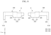
- FIG. 8 is a cross-sectional view taken along line VIII-VIII′ of FIG. 7 .
- FIG. 9 is an enlarged view that illustrates an area Q of FIG. 8 .
- FIG. 10 is an enlarged view that illustrates an area R of FIG. 8 .
- FIG. 11 is a cross-sectional view taken along line XI-XI′ of FIG. 7 .
- the second mold 200 may include a first pressurizing portion 210 , a first pressurizing base portion 220 surrounding the first pressurizing portion 210 and a second pressurizing base portion 230 surrounding the first pressurizing base portion 220 .
- the first pressurizing portion 210 may have a structure in which a lower surface is protruded toward the other side in the third direction Z.
- the lower surface of the first pressurizing portion 210 may protrude in the ⁇ Z direction.
- the first pressurizing portion 210 may correspond to the first support 111 of the first mold 100 .
- the first pressurizing portion 210 may be disposed on the first support 111 .
- Lower surfaces 211 e , 211 b , 212 b and 212 e that are protruded surfaces of the first pressurizing portion 210 may conform with the upper surfaces 111 au and 111 bu of the first support 111 .
- a lower surface of the first pressurizing portion 210 is substantially flat at the center, and an edge of the first pressurizing portion 210 may be a curved surface curved toward the other side in the third direction Z from the outside to the inside.
- a plane shape of the first pressurizing portion 210 may be a circular shape but is not necessarily limited thereto. Various modifications may be made in the plane shape of the first pressurizing portion 210 depending on the design of the cover window CW to be processed.
- the first pressurizing portion 210 for processing a cover window CW having a polygonal plane shape may have a polygonal plane shape
- the first pressurizing portion 210 for processing a cover window CW having an elliptical plane shape may have an elliptical plane shape.
- the first pressurizing portion 210 may include a first sub-pressurizing portion 211 having a first thickness a 1 and a second sub-pressurizing portion 212 having a second thickness a 2 which is thinner than the first thickness a 1 .
- the first thickness a 1 of the first sub-pressurizing portion 211 may be defined as a distance between a flat upper surface 211 u and the flat lower surface 211 b in the first sub-pressurizing portion 211 .
- the second thickness a 2 of the second sub-pressurizing portion 212 may be defined as a distance between a flat upper surface 212 u and the flat lower surface 212 b in the second sub-pressurizing portion 212 .
- the first sub-pressurizing portion 211 may be positioned on one side in the second direction Y of the second sub-pressurizing portion 212
- the second sub-pressurizing portion 212 may be positioned on the other side in the second direction Y of the first sub-pressurizing portion 211 .
- the flat lower surface 211 b of the first sub-pressurizing portion 211 and the flat lower surface 212 b of the second sub-pressurizing portion 212 may be positioned on the same plane. That is, a step difference might not be formed between the flat lower surface 211 b of the first sub-pressurizing portion 211 and the flat lower surface 212 b of the second sub-pressurizing portion 212 . This is illustrated in the embodiment depicted in FIG. 9 .
- the upper surface 211 u of the first sub-pressurizing portion 211 may be positioned on one side in the third direction Z rather than on the upper surface 212 u of the second sub-pressurizing portion 212 .
- a side surface 211 s of the first sub-pressurizing portion 211 may be disposed between the upper surface 211 u of the first sub-pressurizing portion 211 and the upper surface 212 u of the second sub-pressurizing portion 212 .
- the side surface 211 s of the first sub-pressurizing portion 211 may be a boundary between the first sub-pressurizing portion 211 and the second sub-pressurizing portion 212 .
- a step difference of a third thickness a 3 may be formed in an area where the first sub-pressurizing portion 211 and the second sub-pressurizing portion 212 meet on the upper surfaces 211 u and 212 u of the first pressurizing portion 210 .
- the third thickness a 3 may be the same as a difference between the first thickness a 1 and the second thickness a 2 .
- the third thickness a 3 may range from about 1 mm to about 5 mm.
- the first pressurizing portion 210 may include a first sub-pressurizing portion 211 and a second sub-pressurizing portion 212 , which have their respective thicknesses a 1 and a 2 different from each other, thereby forming a step difference on the upper surfaces 211 u and 212 u . Therefore, in a pressurizing process using the pressurizing member (see ‘STG 2 ’ of FIG. 13 ), which pressurizes the first pressurizing portion 210 in contact with the upper surfaces 211 u and 212 u of the first pressurizing portion 210 , a uniform pressurizing force may be transferred to the lower surface of the first pressurizing portion 210 for each area.
- the first pressurizing base portion 220 may be disposed to surround the first pressurizing portion 210 .
- a plane shape of an external appearance of the first pressurizing base portion 220 may be a rectangular shape, but is not necessarily limited thereto.
- the lower surface of the first pressurizing base portion 220 may be positioned on one side in the third direction Z rather than on the lower surface of the first pressurizing portion 210 . That is, the lower surface of the first pressurizing portion 210 may have a structure protruded toward the other side in the third direction Z (e.g., in the ⁇ Z direction) rather than toward the lower surface of the first pressurizing base portion 220 .
- the second pressurizing base portion 230 may be disposed outside the first pressurizing base portion 220 .
- the second pressurizing base portion 230 may be disposed to surround the first pressurizing base portion 220 .
- the second pressurizing base portion 230 may include a first sub-pressurizing base portion 231 disposed on one end and the other end in the first direction X of the second mold 200 , a second sub-pressurizing base portion 232 disposed on an inner side rather than on the first sub-pressurizing base portion 231 , a third sub-pressurizing base portion 233 disposed on one side in the second direction Y of the first pressurizing base portion 220 , and a fourth sub-pressurizing base portion 234 disposed on one side in the second direction Y of the third sub-pressurizing base portion 233 .
- the first sub-pressurizing base portion 231 may be positioned on one end and the other end in the first direction X of the second mold 200 .
- the first sub-pressurizing base portion 231 may have a shape which extends longwise in the second direction Y.
- the first sub-pressurizing base portion 231 may have a shape in which the other end in the second direction Y is protruded toward an inner side of the second mold 200 .
- the second sub-pressurizing base portion 232 may have a shape which extends longwise in the second direction Y.
- the second sub-pressurizing base 232 may have a shape in which the other end in the second direction Y is recessed toward the inner side of the second mold 200 .
- a lower surface of the second sub-pressurizing base portion 232 may be positioned on the other side in the third direction Z rather than on the lower surface of the first pressurizing base portion 220 .
- the lower surface of the second sub-pressurizing base portion 232 may be positioned on the other side in the third direction Z rather than on the lower surface of the first sub-pressurizing base portion 231 .
- the third sub-pressurizing base portion 233 may have a shape which extends longwise in the first direction X.
- the third sub-pressurizing base portion 233 may be positioned on one side in the second direction Y of the first pressurizing base portion 220 .
- the third sub-pressurizing base portion 233 may be disposed between the first sub-pressurizing base portion 231 disposed on one side in the first direction X and the first sub-pressurizing base portion 231 disposed on the other side in the first direction X.
- the third sub-pressurizing base portion 233 may be disposed between the second sub-pressurizing base portion 232 disposed on one side in the first direction X and the second sub-pressurizing base portion 232 disposed on the other side in the first direction X.
- a lower surface of the third sub-pressurizing base portion 233 may be positioned on one side in the third direction Z rather than on the lower surface of the first pressurizing base portion 220 .
- the lower surface of the third sub-pressurizing base portion 233 may be positioned on one side in the third direction Z rather than on the lower surface of the second sub-pressurizing base portion 232 .
- the lower surface of the third sub-pressurizing base portion 233 may be positioned on one side in the third direction Z rather than a lower surface of the fourth sub-pressurizing base portion 234 , which will be described later.
- the fourth sub-pressurizing base portion 234 may be disposed on one end in the second direction Y of the second mold 200 , and may be surrounded by the third sub-pressurizing base portion 233 on a plane.
- the lower surface of the fourth sub-pressurizing base portion 234 may be positioned on the other side in the third direction Z rather than on the lower surface of the third sub-pressurizing base portion 233 .
- the third mold 300 may have a structure substantially the same as that of the second mold 200 described above.
- the third mold 300 may include a second pressurizing portion 310 , a third pressurizing base portion 320 surrounding the second pressurizing portion 310 , and a fourth pressurizing base portion 330 surrounding the third pressurizing base portion 320 .
- the second pressurizing portion 310 may have a structure in which the lower surface is protruded toward the other side in the third direction Z.
- the lower surface of the second pressurizing portion 310 may protrude in the ⁇ Z direction.
- the second pressurizing portion 310 may correspond to the second support 112 of the first mold 100 .
- the second pressurizing portion 310 may be disposed on the second support 112 .
- Lower surfaces 311 e , 311 b , 312 b and 312 e of the second pressurizing portion 310 may conform with the upper surfaces 112 au and 112 bu of the second support 112 .
- a plane shape of the second pressurizing portion 310 may be a circular shape, but is not necessarily limited thereto. Various modifications may be made in the plane shape of the second pressurizing portion 310 depending on the design of the cover window CW to be processed.
- the second pressurizing portion 310 for processing a cover window CW having a polygonal plane shape may have a polygonal plane shape
- the second pressurizing portion 310 for processing a cover window CW having an elliptical plane shape may have an elliptical plane shape.
- the second pressurizing portion 310 may include a third sub-pressurizing portion 311 having a fourth thickness b 1 and a fourth sub-pressurizing portion 312 having a fifth thickness b 2 which is thinner than the third thickness a 3 .
- the fourth thickness b 1 of the third sub-pressurizing portion 311 may be defined as a distance between a flat upper surface 311 u and the flat lower surface 311 b in the third sub-pressurizing portion 311 .
- the fifth thickness b 2 of the fourth sub-pressurizing portion 312 may be defined as a distance between a flat upper surface 312 u and the flat lower surface 312 b in the fourth sub-pressurizing portion 312 .
- the fourth thickness b 1 may substantially be the same as the first thickness a 1
- the fifth thickness b 2 may substantially be the same as the second thickness a 2 .
- the third sub-pressurizing portion 311 may be positioned on one side in the second direction Y of the fourth sub-pressurizing portion 312
- the fourth sub-pressurizing portion 312 may be positioned on one side in the second direction Y of the third sub-pressurizing portion 311 .
- the flat lower surface 311 b of the third sub-pressurizing portion 311 and the flat lower surface 312 b of the fourth sub-pressurizing portion 312 may be positioned on the same plane. That is, a step difference might not be formed between the flat lower surface 311 b of the third sub-pressurizing portion 311 and the lower surface 312 b of the fourth sub-pressurizing portion 312 .
- the upper surface 311 u of the third sub-pressurizing portion 311 may be positioned on one side in the third direction Z rather than on the upper surface 312 u of the fourth sub-pressurizing portion 312 .
- a side surface 311 s of the third sub-pressurizing portion 311 which has a sixth thickness b 3 , may be disposed between the upper surface of the third sub-pressurizing portion 311 and the upper surface of the fourth sub-pressurizing portion 312 .
- the side surface 311 s of the third sub-pressurizing portion 311 may be a boundary between the third sub-pressurizing portion 311 and the fourth sub-pressurizing portion 312 .
- a step difference of the sixth thickness b 3 may be formed in an area where the third sub-pressurizing portion 311 and the fourth sub-pressurizing portion 312 meet on the upper surfaces 311 u and 312 u of the second pressurizing portion 310 .
- the sixth thickness b 3 may be the same as a difference between the fourth thickness b 1 and the fifth thickness b 2 .
- the sixth thickness b 3 may range from about 1 mm to about 5 mm.
- the second pressurizing portion 310 may include a third sub-pressurizing portion 311 and a fourth sub-pressurizing portion 312 , which have their respective thicknesses difference from each other, thereby forming a step difference between the heights of the upper surfaces 311 u and 312 u . Therefore, in a pressurizing process using the pressurizing member STG 2 , which pressurizes the second pressurizing portion 310 in contact with the upper surfaces 311 u and 312 u of the second pressurizing portion 310 , a uniform pressurizing force may be transferred to the lower surface of the second pressurizing portion 310 for each area.
- the third pressurizing base portion 320 may surround the second pressurizing portion 310 .
- a plane shape of the third pressurizing base portion 320 may be a rectangular shape, but is not necessarily limited thereto.
- a lower surface of the third pressurizing base portion 320 may be positioned on one side in the third direction Z rather than on the lower surface of the second pressurizing portion 310 .
- the lower surface of the second pressurizing portion 310 may have a structure which protrudes toward the other side in the third direction Z (e.g., the ⁇ Z direction) rather than toward the lower surface of the third pressurizing base portion 320 .
- the fourth pressurizing base portion 330 may be disposed outside the third pressurizing base portion 320 .
- the fourth pressurizing base portion 330 may surround the third pressurizing base portion 320 .
- the fourth pressurizing base portion 330 may include a fifth sub-pressurizing base portion 331 disposed on one end and the other end in the first direction X of the third mold 300 , a sixth sub-pressurizing base portion 332 disposed on an inner side rather than on the fifth sub-pressurizing base portion 331 , a seventh sub-pressurizing base portion 333 disposed on the other side in the second direction Y of the third pressurizing base portion 320 , and an eighth sub-pressurizing base portion 334 disposed on the other side in the second direction Y of the seventh sub-pressurizing base portion 333 .
- the fifth sub-pressurizing base portion 331 may be positioned on one end and the other end in the first direction X of the third mold 300 .
- the fifth sub-pressurizing base portion 331 may have a shape which extends longwise in the second direction Y.
- the fifth sub-pressurizing base portion 331 may have a shape in which one end in the second direction Y is protruded toward an inner side of the third mold 300 .
- the sixth sub-pressurizing base portion 332 may have a shape which extends longwise in the second direction Y.
- the sixth sub-pressurizing base 332 may have a shape in which one end in the second direction Y is recessed toward the inner side of the third mold 300 .
- a lower surface of the sixth sub-pressurizing base portion 332 may be positioned on the other side in the third direction Z rather than on the lower surface of the third pressurizing base portion 320 .
- the lower surface of the sixth sub-pressurizing base portion 332 may be positioned on the other side in the third direction Z rather than on the lower surface of the fifth sub-pressurizing base portion 331 .
- the seventh sub-pressurizing base portion 333 may have a shape which extends longwise in the first direction X.
- the seventh sub-pressurizing base portion 333 may be positioned on the other side in the second direction Y of the third pressurizing base portion 320 .
- the seventh sub-pressurizing base portion 333 may be disposed between the fifth sub-pressurizing base portion 331 disposed on one side in the first direction X and the fifth sub-pressurizing base portion 331 disposed on the other side in the first direction X.
- the seventh sub-pressurizing base portion 233 may be disposed between the sixth sub-pressurizing base portion 332 disposed on one side in the first direction X and the sixth sub-pressurizing base portion 332 disposed on the other side in the first direction X.
- a lower surface of the seventh sub-pressurizing base portion 333 may be positioned on one side in the third direction Z rather than on the lower surface of the third pressurizing base portion 320 .
- the lower surface of the seventh sub-pressurizing base portion 333 may be positioned on one side in the third direction Z rather than on the lower surface of the sixth sub-pressurizing base portion 332 .
- the lower surface of the seventh sub-pressurizing base portion 333 may be positioned on one side in the third direction Z rather than a lower surface of the eighth sub-pressurizing base portion 334 , which will be described later.
- the eighth sub-pressurizing base portion 334 may be disposed on the other end in the second direction Y of the third mold 300 , and may be surrounded by the seventh sub-pressurizing base portion 333 on a plane.
- the lower surface of the eighth sub-pressurizing base portion 334 may be positioned on the other side in the third direction Z rather than on the lower surface of the eighth sub-pressurizing base portion 333 .
- FIGS. 12 to 14 a processing procedure for processing a cover window CW using an apparatus 1 for processing a cover window according to one embodiment of the present disclosure will be described with reference to FIGS. 12 to 14 .
- FIGS. 12 to 14 are schematic views that illustrate a process for processing a cover window, using an apparatus for processing a cover window according to one embodiment of the present disclosure.
- the apparatus 1 for processing a cover window may further include a stage STG 1 and a pressurizing member STG 2 .
- the first mold 100 may be seated on the stage STG 1 .
- the first mold is disposed on the stage STG 1 , a first processing target SMP 1 is disposed on the first support 111 of the first mold 100 , and a second processing target SMP 2 is disposed on the second support 112 .
- the first processing target SMP 1 and the second processing target SMP 2 may be processed into a cover window CW by using the apparatus 1 for processing a cover window according to one embodiment.
- the first processing target SMP 1 and the second processing target SMP 2 may be made of glass.
- the first processing target SMP 1 and the second processing target SMP 2 may be the substantially same elements.
- a first virtual surface IL 1 defining a boundary between the first sub-pressurizing portion 211 and the second sub-pressurizing portion 212 may divide the first support 111 into two portions.
- the first virtual surface IL 1 may be a plane that extends from the side surface 211 s of the first sub-pressurizing portion 211 .
- an area of the first support 111 which is overlapped with the first sub-pressurizing portion 211 , may be symmetrical with an area of the first support 111 , which is overlapped with the second sub-pressurizing portion 212 , based on the first virtual surface IL 1 .
- a second virtual surface IL 2 defining a boundary between the third sub-pressurizing portion 311 and the fourth sub-pressurizing portion 312 may divide the second support 112 into two portions.
- the second virtual surface IL 2 may be a plane that extends from the side surface 311 s of the third sub-pressurizing portion 311 .
- an area of the second support 112 which is overlapped with the third sub-pressurizing portion 311 , may be symmetrical with an area of the second support 112 , which is overlapped with the fourth sub-pressurizing portion 312 , based on the second virtual surface IL 2 .
- the second mold 200 is brought into contact with the upper surface of the first processing target SMP 1
- the third mold 300 is brought into contact with the upper surface of the second processing target SMP 2
- the lower surface of the first pressurizing portion 210 of the second mold 200 is brought into contact with the upper surface of the first processing target SMP 1
- the lower surface of the second pressurizing portion 310 of the third mold 300 is brought into contact with the upper surface of the second processing target SMP 2 .
- the pressurizing member STG 2 may be disposed on the second mold 200 and the third mold 300 .
- the pressurizing member STG 2 may a rigid or semi-rigid structure such as a press that, when pressed against the second mold 200 and third mold 300 , pressurizes the first pressurizing portion 210 of the second mold 200 and the second pressurizing portion 310 of the third mold 300 .
- the pressurizing member STG 2 may include a heater HT to provide heat to the second mold 200 and the third mold 300 .
- the heater HIT may be disposed on a lower portion of the pressurizing member STG 2 , but is not necessarily limited thereto.
- the heater HT may be disposed inside the pressurizing member STG 2 .
- a pressurizing axis FA may be connected to the pressurizing member STG 2 , and may pressurize the pressurizing member STG 2 toward the other side in the third direction Z.
- the pressurizing axis FA may pressurize the pressurizing member STG 2 in the ⁇ Z direction.
- the pressurizing axis FA may be positioned at the center of the pressurizing member STG 2 . Therefore, a pressurizing force applied to the pressurizing member STG 2 is the greatest at the center, and may be reduced toward the edge of the pressurizing member STG 2 .
- the second mold 200 and the third mold 300 may be pressurized by the pressurizing member STG 2 using the pressurizing axis FA.
- the pressurizing force provided to the second mold 200 and the third mold 300 may be uniform for each area even though the pressurizing axis FA is positioned at the center of the pressurizing member STG 2 .
- the pressurizing force applied to the first processing target SMP 1 and the second processing target SMP 2 may substantially be uniform for each area. Therefore, a processing defect rate of the cover window CW may be lowered through uniform pressurization.
- a uniform pressure may be transferred to each area of each cover window CW processed by the above described method for processing the cover window CW that includes a curved edge.
- the uniform pressure is achieved at least in part through the second mold 200 that includes a first pressurizing portion 210 having a step difference formed on an upper surface and the third mold 300 that includes a second pressurizing portion 310 having a step difference formed on an upper surface. Therefore, defects due to non-uniform pressurization that may occur during the process of processing the cover window CW may be reduced.
- the apparatus 1 for processing a cover window according to another embodiment will be described based on a difference from the apparatus 1 for processing a cover window according to one embodiment of the present disclosure.
- FIG. 15 is a schematic view that illustrates an apparatus for processing a cover window according to one embodiment of the present disclosure.
- an apparatus 1 _ 1 for processing a cover window is different from the apparatus 1 in that a first mold 100 _ 1 further includes a third support 113 _ 1 disposed between a first support 111 _ 1 and a second support 112 _ 1 and the apparatus 1 _ 1 further includes a fourth mold 400 disposed on the third support 113 _ 1 .
- the first mold 100 may include first to third supports 111 _ 1 , 112 _ 1 and 113 _ 1 .
- the first to third supports 111 _ 1 , 112 _ 1 and 113 _ 1 may be arranged along a second direction (e.g., a second direction Y).
- the first support 111 _ 1 may be disposed on one side of the second direction of the first mold 100
- the second support 112 _ 1 may be disposed on the other side in the second direction of the first mold 100
- the third support 113 _ 1 may be disposed between the first support 111 _ 1 and the second support 112 _ 1 .
- the first to third supports 111 _ 1 , 112 _ 1 and 113 _ 1 may have the same structure.
- a fifth exhaust portion 128 _ 1 may be disposed between the first support 111 _ 1 and the third support 113 _ 1 and between the second support 112 _ 1 and the third support 113 _ 1 .
- the apparatus 1 _ 1 for processing a cover window may include a second mold 200 disposed on the first support 111 _ 1 and a third mold 300 disposed on the second support 112 _ 1 .
- the second mold 200 and the third mold 300 may substantially be the same as the second mold 200 and the third mold 300 described above, which are included in the apparatus 1 for processing a cover window according to one embodiment. Therefore, in the present embodiment, the description of the second mold 200 and the third mold 300 will be omitted.
- the fourth mold 400 may be disposed on the third support 113 _ 1 of the first mold 100 .
- the fourth mold 400 may include a fourth pressurizing portion 410 .
- An upper surface of the fourth pressurizing portion 410 may be substantially flat.
- a lower surface of the fourth pressurizing portion 410 may have a flat central portion, and an edge portion thereof may include a curved surface.
- the lower surface of the fourth pressurizing portion 410 may have a structure substantially the same as that of each of the lower surface of the second pressurizing portion 210 of the second mold 200 and the lower surface of the third pressurizing portion 310 of the third mold 300 .
- the fourth pressurizing portion 410 may have a seventh thickness c 1 .
- the seventh thickness c 1 of the fourth pressurizing portion 410 may be defined as a distance between flat upper and lower surfaces of the fourth pressurizing portion 410 .
- the seventh thickness c 1 may be thinner than the second thickness a 2 and thinner than the fifth thickness b 2 , but is not necessarily limited thereto.
- the seventh thickness c 1 may substantially be the same as the second thickness a 2 and the fifth thickness b 2 .
- a uniform pressure may be transferred to each area of each of the cover windows CW processed by a process of processing the cover window CW that includes a curved edge.
- This uniform pressure may be applied through the second mold 200 that includes a first pressurizing portion 210 having a step difference formed on an upper surface and the third mold 300 that includes a second pressurizing portion 310 having a step difference formed on an upper surface. Therefore, defects due to non-uniform pressurization that may occur during the process of processing the cover window CW may be reduced.
- a larger number of cover windows CW may be processed atone time by the apparatus 1 _ 1 through the first mold 100 that includes the third support 113 _ 1 disposed between the first support 111 _ 1 and the second support 112 _ 1 and the fourth mold 400 disposed on the third support 113 _ 1 .
- FIG. 16 is a schematic view that illustrates an apparatus for processing a cover window according to one embodiment of the present disclosure.
- FIG. 17 is an enlarged view that illustrates an area S of FIG. 16 .
- FIG. 18 is an enlarged view that illustrates an area T of FIG. 16 .
- An apparatus 1 _ 2 for processing a cover window according to the present embodiment is different from the apparatus 1 in that the upper surfaces of a second mold 200 _ 2 and a third mold 300 _ 2 include inclined surfaces.
- a thickness of a first pressurizing portion 210 _ 2 included in the second mold 200 _ 2 may become smaller toward the other side in the second direction Y.
- one end in the second direction Y of the first pressurizing portion 210 _ 2 may have a first thickness a 1 _ 2
- the other end in the second direction Y thereof may have a second thickness a 2 _ 2 thinner than the first thickness a 1 _ 2 .
- the thicknesses a 1 _ 2 and a 2 _ 2 of the first pressurizing portion 210 _ 2 may gradually be reduced toward the second thickness a 2 _ 2 from the first thickness a 1 _ 2 as the first pressurizing portion 210 _ 2 is oriented toward the other end in the second direction Y from one end in the second direction Y.
- the first pressurizing portion 2102 included in the second mold 200 _ 2 may include an inclined upper surface 210 u _ 2 .
- An inclined angle of the upper surface 210 u _ 2 of the first pressurizing portion 210 _ 2 may be a first angle ⁇ 1 .
- the inclined angle of the upper surface 210 u _ 2 of the first pressurizing portion 210 _ 2 may be defined as an incline of the upper surface 210 u _ 2 of the first pressurizing portion 210 _ 2 with respect to a plane parallel with the lower surface 210 b of the first pressurizing portion 210 _ 2 .
- thicknesses b 1 _ 2 and b 2 _ 2 of a second pressurizing portion 310 _ 2 included in the third mold 3002 may become smaller toward one side in the second direction Y.
- the other end in the second direction Y of the second pressurizing portion 3102 may have a fourth thickness b 1 _ 2
- one end in the second direction Y thereof may have a fifth thickness b 2 _ 2 thinner than the fourth thickness b 1 _ 2 .
- the thicknesses of the second pressurizing portion 310 _ 2 may gradually be reduced toward the fifth thickness b 2 _ 2 from the fourth thickness b 1 _ 2 as the second pressurizing portion 310 _ 2 is oriented toward one end in the second direction Y from the other end in the second direction Y.
- the second pressurizing portion 310 _ 2 included in the third mold 300 _ 2 may include an inclined upper surface 310 u _ 2 .
- An inclined angle of the upper surface 310 u _ 2 of the second pressurizing portion 310 _ 2 may be a second angle ⁇ 2 .
- the inclined angle of the upper surface 310 u _ 2 of the second pressurizing portion 310 _ 2 may be defined as an incline of the upper surface of the second pressurizing portion 310 _ 2 with respect to a plane parallel with the lower surface 310 b of the second pressurizing portion 310 _ 2 .
- a uniform pressure may be transferred to each area of the cover window CW processed by a process of processing the cover window CW that includes a curved edge, through the second mold 200 _ 2 that includes a first pressurizing portion 210 _ 2 having an inclined upper surface 210 u _ 2 and the third mold 300 _ 2 that includes a second pressurizing portion 310 _ 2 having an inclined upper surface 310 u _ 2 . Therefore, defects due to non-uniform pressurization that may occur during the process of processing the cover window CW may be reduced.
- first pressurizing portion 210 _ 2 and the second pressurizing portion 310 _ 2 include the upper surfaces 210 u _ 2 and 310 u _ 2 that are inclined, the pressurizing force applied to the other side in the third direction Z may be more uniformly transferred to the pressurizing target during the pressurizing process. In this way, defects due to non-uniform pressurization that may occur during the process of processing the cover window CW may be more reduced.
- FIG. 19 is a schematic view that illustrates an apparatus for processing a cover window according to further one embodiment of the present disclosure.
- an apparatus 13 for processing a cover window is different from the apparatus 1 in that a first mold includes a first support 111 _ 3 and a second support 112 _ 3 , which have respective structures and sizes that are different from each other, and correspondingly, a second mold 200 _ 3 and a third mold 300 _ 3 which have respective structures and sizes different from each other.
- the apparatus 13 for processing a cover window may include a first support 111 _ 3 having a first width W 1 and a second support 1123 having a second width W 2 wider than the first width W 1 .
- FIG. 19 illustrates an embodiment in which the first support 111 _ 3 and the second support 112 _ 3 have respective sizes that are different from each other, but the present disclosure is not necessarily limited thereto.
- the first support 111 _ 3 and the second support 112 _ 3 may be different from each other in plane shapes of the upper surfaces.
- the apparatus 13 for processing a cover window may include a second mold 200 _ 3 that includes a first pressurizing portion 210 _ 3 having a first width W 1 .
- the first pressurizing portion 210 _ 3 may include a first sub-pressurizing portion 211 _ 3 disposed on one side in the second direction Y and a second sub-pressurizing portion 212 _ 3 disposed on the other side in the second direction Y of the first sub-pressurizing portion 211 _ 3 .
- the first sub-pressurizing portion 211 _ 3 may have a first thickness a 1 _ 3
- the second sub-pressurizing portion 212 _ 3 may have a second thickness a 2 _ 3 that is thinner than the first thickness a 1 _ 3
- a step difference in height may be formed between an upper surface of the first sub-pressurizing portion 211 _ 3 and an upper surface of the second sub-pressurizing portion 212 _ 3 .
- the apparatus 1 _ 3 for processing a cover window may include a third mold 300 _ 3 that includes a second pressurizing portion 310 _ 3 having a second width W 2 that is wider than the first width W 1 .
- the second pressurizing portion 310 _ 3 may include a third sub-pressurizing portion 311 _ 3 disposed on the other side in the second direction Y and a fourth sub-pressurizing portion 312 _ 3 disposed on one side in the second direction Y of the third sub-pressurizing portion 311 _ 3 .
- the third sub-pressurizing portion 311 _ 3 may have a fourth thickness b 1 _ 3
- the fourth sub-pressurizing portion 312 _ 3 may have a fifth thickness b 2 _ 3 that is thinner than the third thickness a 1 _ 3
- the fourth thickness b 1 _ 3 may be thinner than the first thickness a 1 _ 3
- the fifth thickness b 2 _ 3 may be thinner than the second thickness a 2 _ 3
- a step difference may be formed between the upper surface of the third sub-pressurizing portion 311 _ 3 and the upper surface of the fourth sub-pressurizing portion 312 _ 3 .
- a uniform pressure may be transferred to each area of each of the cover windows CW processed by a process of processing the cover window CW that includes a curved edge, through the second mold 200 _ 3 that includes a first pressurizing portion 210 _ 3 having an inclined upper surface and the third mold 300 _ 3 that includes a second pressurizing portion 310 _ 3 having an inclined upper surface. Therefore, defects due to non-uniform pressurization that may occur during the process of processing the cover window CW may be reduced.
- the apparatus 1 _ 3 for processing a cover window may process the cover window CW having different sizes through one-time processing procedure.
- Embodiments of the present disclosure may be prevent process defects in the manufacture and processing of cover windows by providing an even pressurization of processing targets through the stepped height structure of pressurization molds. Further, embodiments of the present disclosure provide an apparatus and a method for processing a cover window that allows for the simultaneous processing of multiple cover windows using a single pressurization axis with the stepped molds, thereby increasing a manufacture throughput.
Landscapes
- Chemical & Material Sciences (AREA)
- Engineering & Computer Science (AREA)
- Materials Engineering (AREA)
- Organic Chemistry (AREA)
- Mechanical Engineering (AREA)
- Manufacturing & Machinery (AREA)
- Life Sciences & Earth Sciences (AREA)
- Forests & Forestry (AREA)
- Re-Forming, After-Treatment, Cutting And Transporting Of Glass Products (AREA)
- Moulds For Moulding Plastics Or The Like (AREA)
Abstract
Description
Claims (19)
Applications Claiming Priority (2)
| Application Number | Priority Date | Filing Date | Title |
|---|---|---|---|
| KR1020210083560A KR102956446B1 (en) | 2021-06-28 | Apparatus for processing cover window and method for processing cover window | |
| KR10-2021-0083560 | 2021-06-28 |
Publications (2)
| Publication Number | Publication Date |
|---|---|
| US20220411313A1 US20220411313A1 (en) | 2022-12-29 |
| US12134576B2 true US12134576B2 (en) | 2024-11-05 |
Family
ID=84542156
Family Applications (1)
| Application Number | Title | Priority Date | Filing Date |
|---|---|---|---|
| US17/661,808 Active 2042-07-01 US12134576B2 (en) | 2021-06-28 | 2022-05-03 | Apparatus for processing cover window and method for processing cover window |
Country Status (2)
| Country | Link |
|---|---|
| US (1) | US12134576B2 (en) |
| CN (1) | CN115592741A (en) |
Citations (3)
| Publication number | Priority date | Publication date | Assignee | Title |
|---|---|---|---|---|
| KR20130108257A (en) | 2010-08-30 | 2013-10-02 | 코닝 인코포레이티드 | Apparatus and method for shaping a glass substrate |
| KR20170045967A (en) | 2015-10-20 | 2017-04-28 | 엘지전자 주식회사 | Die for bending and bending method using the same |
| KR20190051228A (en) | 2017-11-06 | 2019-05-15 | 주식회사 부일신소재 | Parts of wrist watch using carbon composite and method for manufacturing the same |
-
2022
- 2022-05-03 US US17/661,808 patent/US12134576B2/en active Active
- 2022-05-07 CN CN202210490005.1A patent/CN115592741A/en active Pending
Patent Citations (3)
| Publication number | Priority date | Publication date | Assignee | Title |
|---|---|---|---|---|
| KR20130108257A (en) | 2010-08-30 | 2013-10-02 | 코닝 인코포레이티드 | Apparatus and method for shaping a glass substrate |
| KR20170045967A (en) | 2015-10-20 | 2017-04-28 | 엘지전자 주식회사 | Die for bending and bending method using the same |
| KR20190051228A (en) | 2017-11-06 | 2019-05-15 | 주식회사 부일신소재 | Parts of wrist watch using carbon composite and method for manufacturing the same |
Non-Patent Citations (1)
| Title |
|---|
| Machine translation of KR 10-20170045967 A1 (Year: 2017). * |
Also Published As
| Publication number | Publication date |
|---|---|
| US20220411313A1 (en) | 2022-12-29 |
| CN115592741A (en) | 2023-01-13 |
| KR20230001561A (en) | 2023-01-05 |
Similar Documents
| Publication | Publication Date | Title |
|---|---|---|
| US11610520B2 (en) | Foldable display apparatus | |
| US11347266B2 (en) | Cover glass and manufacturing method thereof | |
| US9346252B2 (en) | Display module and manufacturing method thereof | |
| US6654088B2 (en) | Liquid crystal display device | |
| US9987826B2 (en) | Display device having adhesion layer between curved window panel and curved display panel | |
| JP5268761B2 (en) | Display device and manufacturing method thereof | |
| CN111129086A (en) | Flexible display panel and manufacturing method thereof | |
| US11820693B2 (en) | Method of molding window for display | |
| US8582046B2 (en) | Liquid crystal display and method thereof | |
| US9693422B2 (en) | Curved display device | |
| US20170160580A1 (en) | Curved display device and method for manufacturing the same | |
| US10031281B2 (en) | Display apparatus | |
| CN1987569A (en) | Liquid crystal display device and method for manufacturing liquid crystal device | |
| US20180136504A1 (en) | Curved surface display panel and display device | |
| US10712613B2 (en) | Backlight unit and display device | |
| WO2014141842A1 (en) | Display device and method for manufacturing same | |
| US20130002976A1 (en) | Backlight structure and display module using the same | |
| CN117337627B (en) | Heat dissipation component, display module and display device | |
| US10908352B1 (en) | Back plate including receiving slots back plate assembly, backlight module and display device | |
| US12134576B2 (en) | Apparatus for processing cover window and method for processing cover window | |
| WO2018090899A1 (en) | Backlight module and display module | |
| CN101241257A (en) | A kind of manufacturing method of backlight module and its base | |
| JP2015215598A (en) | Display panel and cutting method thereof | |
| US20080007669A1 (en) | Fabricating method for liquid crystal device and system for displaying image | |
| TWI485478B (en) | Backlight module having reflective layer and display apparatus thereof |
Legal Events
| Date | Code | Title | Description |
|---|---|---|---|
| AS | Assignment |
Owner name: SAMSUNG DISPLAY CO., LTD., KOREA, REPUBLIC OF Free format text: ASSIGNMENT OF ASSIGNORS INTEREST;ASSIGNORS:LEE, SUN HO;SHIN, JIN SOO;REEL/FRAME:059797/0654 Effective date: 20220124 |
|
| FEPP | Fee payment procedure |
Free format text: ENTITY STATUS SET TO UNDISCOUNTED (ORIGINAL EVENT CODE: BIG.); ENTITY STATUS OF PATENT OWNER: LARGE ENTITY |
|
| STPP | Information on status: patent application and granting procedure in general |
Free format text: DOCKETED NEW CASE - READY FOR EXAMINATION |
|
| STPP | Information on status: patent application and granting procedure in general |
Free format text: NON FINAL ACTION MAILED |
|
| STPP | Information on status: patent application and granting procedure in general |
Free format text: RESPONSE TO NON-FINAL OFFICE ACTION ENTERED AND FORWARDED TO EXAMINER |
|
| STPP | Information on status: patent application and granting procedure in general |
Free format text: NOTICE OF ALLOWANCE MAILED -- APPLICATION RECEIVED IN OFFICE OF PUBLICATIONS |
|
| STPP | Information on status: patent application and granting procedure in general |
Free format text: PUBLICATIONS -- ISSUE FEE PAYMENT RECEIVED |
|
| STPP | Information on status: patent application and granting procedure in general |
Free format text: PUBLICATIONS -- ISSUE FEE PAYMENT VERIFIED |
|
| STCF | Information on status: patent grant |
Free format text: PATENTED CASE |