US12130415B2 - Imaging optical system and imaging device - Google Patents
Imaging optical system and imaging device Download PDFInfo
- Publication number
- US12130415B2 US12130415B2 US17/421,733 US202017421733A US12130415B2 US 12130415 B2 US12130415 B2 US 12130415B2 US 202017421733 A US202017421733 A US 202017421733A US 12130415 B2 US12130415 B2 US 12130415B2
- Authority
- US
- United States
- Prior art keywords
- reflector
- disposed
- variable aperture
- optical
- light
- Prior art date
- Legal status (The legal status is an assumption and is not a legal conclusion. Google has not performed a legal analysis and makes no representation as to the accuracy of the status listed.)
- Active, expires
Links
- 230000003287 optical effect Effects 0.000 title claims abstract description 105
- 238000003384 imaging method Methods 0.000 title claims abstract description 99
- 230000008859 change Effects 0.000 claims abstract description 7
- 230000005499 meniscus Effects 0.000 claims description 6
- 229910052751 metal Inorganic materials 0.000 description 41
- 239000002184 metal Substances 0.000 description 41
- 230000004907 flux Effects 0.000 description 23
- 239000011347 resin Substances 0.000 description 12
- 229920005989 resin Polymers 0.000 description 12
- 230000004075 alteration Effects 0.000 description 3
- 238000010586 diagram Methods 0.000 description 3
- 238000003780 insertion Methods 0.000 description 3
- 230000037431 insertion Effects 0.000 description 3
- 239000007769 metal material Substances 0.000 description 2
- 229910000861 Mg alloy Inorganic materials 0.000 description 1
- 239000002131 composite material Substances 0.000 description 1
- 230000000694 effects Effects 0.000 description 1
- 230000000977 initiatory effect Effects 0.000 description 1
- 239000000463 material Substances 0.000 description 1
- 238000000034 method Methods 0.000 description 1
- 238000012986 modification Methods 0.000 description 1
- 230000004048 modification Effects 0.000 description 1
- 230000008520 organization Effects 0.000 description 1
- 230000002093 peripheral effect Effects 0.000 description 1
- 230000035945 sensitivity Effects 0.000 description 1
- 230000002194 synthesizing effect Effects 0.000 description 1
Images


Classifications
-
- G—PHYSICS
- G02—OPTICS
- G02B—OPTICAL ELEMENTS, SYSTEMS OR APPARATUS
- G02B13/00—Optical objectives specially designed for the purposes specified below
- G02B13/001—Miniaturised objectives for electronic devices, e.g. portable telephones, webcams, PDAs, small digital cameras
- G02B13/0055—Miniaturised objectives for electronic devices, e.g. portable telephones, webcams, PDAs, small digital cameras employing a special optical element
- G02B13/0065—Miniaturised objectives for electronic devices, e.g. portable telephones, webcams, PDAs, small digital cameras employing a special optical element having a beam-folding prism or mirror
-
- G—PHYSICS
- G02—OPTICS
- G02B—OPTICAL ELEMENTS, SYSTEMS OR APPARATUS
- G02B13/00—Optical objectives specially designed for the purposes specified below
- G02B13/001—Miniaturised objectives for electronic devices, e.g. portable telephones, webcams, PDAs, small digital cameras
- G02B13/0015—Miniaturised objectives for electronic devices, e.g. portable telephones, webcams, PDAs, small digital cameras characterised by the lens design
- G02B13/002—Miniaturised objectives for electronic devices, e.g. portable telephones, webcams, PDAs, small digital cameras characterised by the lens design having at least one aspherical surface
- G02B13/0045—Miniaturised objectives for electronic devices, e.g. portable telephones, webcams, PDAs, small digital cameras characterised by the lens design having at least one aspherical surface having five or more lenses
-
- G—PHYSICS
- G02—OPTICS
- G02B—OPTICAL ELEMENTS, SYSTEMS OR APPARATUS
- G02B13/00—Optical objectives specially designed for the purposes specified below
- G02B13/06—Panoramic objectives; So-called "sky lenses" including panoramic objectives having reflecting surfaces
-
- G—PHYSICS
- G02—OPTICS
- G02B—OPTICAL ELEMENTS, SYSTEMS OR APPARATUS
- G02B27/00—Optical systems or apparatus not provided for by any of the groups G02B1/00 - G02B26/00, G02B30/00
- G02B27/10—Beam splitting or combining systems
- G02B27/1066—Beam splitting or combining systems for enhancing image performance, like resolution, pixel numbers, dual magnifications or dynamic range, by tiling, slicing or overlapping fields of view
-
- G—PHYSICS
- G02—OPTICS
- G02B—OPTICAL ELEMENTS, SYSTEMS OR APPARATUS
- G02B27/00—Optical systems or apparatus not provided for by any of the groups G02B1/00 - G02B26/00, G02B30/00
- G02B27/0025—Optical systems or apparatus not provided for by any of the groups G02B1/00 - G02B26/00, G02B30/00 for optical correction, e.g. distorsion, aberration
Definitions
- This disclosure relates to an imaging optical system and an imaging device.
- Patent Literatures 1 and 2 describe imaging systems, capable of capturing full-view spherical images, which include two imaging units, each is configured as a combination of a wide-angle lens having an angle of view greater than 180 degrees and an image sensor used for capturing images using the wide-angle lens, and images captured by the two imaging units are synthesized to obtain an image having a stereoscopic angle of 4a radians.
- the above described light amount adjusting method has a drawback.
- the light amount becomes the limit of the setting range when capturing images in a bright scene, with which an image may have a white area due to saturation of the light amount.
- the light amount becomes the limit of the setting range when capturing images in a dark scene, with which an image may have a dark area.
- variable aperture (variable aperture stop) can be disposed on an optical path.
- a physical variable aperture variable aperture stop
- This disclosure describes an embodiment that is devised in view of the above described issue, in which an imaging optical system and an imaging device that can effectively adjust the light amount while achieving compact in size can be provided.
- an imaging optical system includes a plurality of optical systems each including a plurality of optical members, a first reflection member, disposed for each one of the optical systems, configured to reflect light when the light passing through the plurality of optical members, and a variable aperture member having an opening disposed at an image sensor side when viewed from the first reflection member, the variable aperture member configured to change a size of the opening through which the light reflected from the first reflection member passes through, and at least a part of the variable aperture member is disposed at a position overlapping with an area corresponding to a first lens, disposed at the most object side in the plurality of optical members, along an optical axis direction.
- an imaging device in another aspect of the present invention, includes a plurality of optical systems each including a plurality of optical members, a plurality of image sensors, each disposed for the respective optical systems, configured to generate an image of an object captured by the respective optical systems, a reflection member, disposed for each one of the optical systems, configured to reflect light when the light passing through the plurality of optical members, and a variable aperture member having an opening disposed at an image sensor side when viewed from the reflection member, the variable aperture member configured to change a size of the opening through which the light reflected from the reflection member passes through, and at least a part of the variable aperture member is disposed at a position overlapping with an area corresponding to a first lens, disposed at the most object side in the plurality of optical members, along an optical axis direction.
- an imaging optical system and an imaging device that can effectively adjust the light amount while achieving compact in size can be provided.
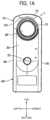
- FIGS. 1 A, 1 B and 1 C illustrate an external configuration of an imaging device according to an embodiment.
- FIG. 2 illustrates a wide-angle lens system and an image sensor disposed inside a casing viewed from a left side.
- FIG. 3 illustrates a wide angle lens system and an image sensor disposed inside a casing viewed from a rear side.
- FIG. 4 illustrates a wide angle lens system and an image sensor disposed inside a casing viewed from a top side.
- FIG. 5 illustrates a detailed configuration of a wide-angle lens system and an image sensor disposed inside a casing.
- FIG. 6 is a first view illustrating a configuration and arrangement of a variable aperture member.
- FIG. 7 is a second view illustrating a configuration and arrangement of the variable aperture member, removing some parts from FIG. 6 .
- FIGS. 1 to 7 a description is given of an imaging device 1 (or imaging optical system) according to an embodiment with reference to FIGS. 1 to 7 .
- directions in front, rear, upper, bottom, left and right correspond to arrow directions described in each drawing.
- the imaging device 1 includes, for example, a casing 10 , in which each of components of the imaging device 1 is assembled and held inside or outside the casing 10 .
- the casing 10 has a contour, which is short along the left-to-right direction, long along the top-to-bottom direction, having a given thickness along the front-to-rear direction, and a given rounded profile at a top side.
- the casing 10 includes, for example, a rear-side metal casing 20 and a front-side metal casing 30 .
- the rear-side metal casing 20 and the front-side metal casing 30 can be formed as a composite molded casing composed of a relatively higher rigidity metal material (e.g., magnesium alloy) compared to a rear-side resin casing 70 , a front-side resin casing 80 , and a connection resin casing 90 to be described later.
- a relatively higher rigidity metal material e.g., magnesium alloy
- the rear-side metal casing 20 and the front-side metal casing 30 are connected by a left-side connection casing 40 , a right-side connection casing 50 , and a bottom-side connection casing 60 .
- the left-side connection casing 40 , the right-side connection casing 50 and the bottom-side connection casing 60 can be made of, for example, the same metal material as the rear-side metal casing 20 and the front-side metal casing 30 , but there is a degree of freedom in the material and various design changes can be made as needed.
- a positioning boss is formed in any one of the rear-side metal casing 20 and the front-side metal casing 30 , and a boss insertion hole is formed on the other one of the rear-side metal casing 20 and the front-side metal casing 30 , so that the rear-side metal casing 20 and the front-side metal casing 30 are positioned at close proximity when the positioning boss is inserted into the boss insertion hole.
- each of the rear-side metal casing 20 and the front-side metal casing 30 includes screw holes at the left-side face, the right-side face, and the bottom face, which overlap with each other when the positioning boss is inserted into the boss insertion hole (positioning state).
- left-side connection casing 40 , the right-side connection casing 50 , and the bottom-side connection casing 60 are fitted into a gap between the rear-side metal casing 20 and the front-side metal casing 30 , and then common screws are screwed (tightened) into the respective screw holes, with which the rear-side metal casing 20 , the front-side metal casing 30 , the left-side connection casing 40 , the right-side connection casing 50 and the bottom-side connection casing 60 are integrated as one casing.
- the configuration of integrating the rear-side metal casing 20 , the front-side metal casing 30 , the left-side connection casing 40 , the right-side connection casing 50 and the bottom-side connection casing 60 has a given degree of freedom, and various design changes can be made as needed.
- a lens exposure hole 21 having a circular shape is formed at a upper portion of the rear-side metal casing 20
- a lens exposure hole 31 having a circular shape is formed at a upper portion of the front-side metal casing 30 .
- a shutter button 22 serving as a trigger for initiating an image capturing operation is provided slightly below a middle portion in the top-to-bottom direction of the rear-side metal casing 20 .
- a power button 51 is provided at a middle portion in the top-to-bottom direction of the right-side connection casing 50 to switch on and off the power supply of the imaging device 1 , and operation buttons 52 , 53 and 54 are provided below the power button 51 to perform setting operations, such as an image capturing mode and a wireless connection mode.
- a portion below the middle in the top-to-bottom direction of the one casing is used as a grip portion GP.
- a user can press the shutter button 22 , the power button 51 , and the operation buttons 52 to 54 while holding the grip portion GP.
- FIGS. 1 A, 1 B and 1 C when the rear-side metal casing 20 , the front-side metal casing 30 , the left-side connection casing 40 , the right-side connection casing 50 , and the bottom-side connection casing 60 are integrated as the one casing, an opening OS that is open to the top side is formed.
- the opening OS is covered by the rear-side resin casing 70 , the front-side resin casing 80 , and the connection resin casing 90 .
- the detail structure of the rear-side resin casing 70 , the front-side resin casing 80 and the connection resin casing 90 (e.g., connection with a structure connecting the rear-side metal casing 20 , the front-side metal casing 30 , the left-side connection casing 40 , the right-side connection casing 50 , and the bottom-side connection casing 60 ) has a given degree of freedom, and various design changes can be made as needed.
- the imaging device 1 includes or houses two wide-angle lens systems A and B (optical systems), and two image sensors AI and BI inside the casing 10 .
- the two wide-angle lens systems A and B are arranged symmetrically with each other inside the casing 10 , and images captured by the two wide-angle lens systems A and B are respectively focused and generated on the two image sensors AI and BI.
- the casing 10 is schematically drawn with a virtual line (two-point dashed line).
- the two wide-angle lens systems A and B can be configured using the same design specification, and the image sensors AI and BI can be configured using the same design specification.
- each of the wide-angle lens systems A and B have an angle of view greater than 180 degrees.
- the imaging device 1 can be used as an imaging device capable of capturing full-view spherical images by synthesizing two images generated by the image sensors AI and BI as an image having a stereoscopic angle of 4a radians.
- the wide-angle lens system A includes, for example, a negative front group AF, a first prism AP 1 (reflection member, first reflection member), a variable aperture member AS (variable aperture stop), a second prism AP 2 (second reflection member), a positive rear group AR, and a third prism AP 3 (third reflection member) in the order from the object side to the image sensor.
- a negative front group AF a first prism AP 1 (reflection member, first reflection member), a variable aperture member AS (variable aperture stop), a second prism AP 2 (second reflection member), a positive rear group AR, and a third prism AP 3 (third reflection member) in the order from the object side to the image sensor.
- the negative front group AF has a function of capturing light ray corresponding to an angle of view greater than 180 degrees
- the positive rear group AR has a function of correcting aberration of the focused image.
- the variable aperture member AS is omitted in FIG. 2 to FIG. 4 while illustrated in FIG. 5 . Further, the detailed configuration and arrangement of the variable aperture member AS will be described later with reference to FIGS. 6 and 7 .
- object light flux When light flux coming from an object (hereinafter, object light flux) enters the negative front group AF, the negative front group AF emits the object light flux from the exit side of the negative front group AF while dispersing the object light flux. Then, the first prism AP 1 reflects the object light flux, incident from the negative front group AF, by 90 degrees to the left direction. Then, the aperture AS adjusts a passing amount of the object light flux reflected by the first prism AP 1 (light amount adjustment). Then, the second prism AP 2 reflects the object light flux having the light amount adjusted by the aperture AS by 90 degrees to the downward direction.
- object light flux When light flux coming from an object (hereinafter, object light flux) enters the negative front group AF, the negative front group AF emits the object light flux from the exit side of the negative front group AF while dispersing the object light flux. Then, the first prism AP 1 reflects the object light flux, incident from the negative front group AF, by 90 degrees to the left direction
- the positive rear group AR emits the object light flux, reflected by the second prism AP 2 , to the downward direction while converging the object light flux.
- the third prism AP 3 reflects the object light flux, incident from the positive rear group AR, by 90 degrees to the right direction to focus and generate an image on an imaging plane of the image sensor AI.
- a convex portion AP 3 X is formed on an exit face of the third prism AP 3 while projecting toward the imaging plane of the image sensor AI.
- each of the negative front group AF and the positive rear group AR consists of a plurality of lenses, and the plurality of lenses is represented as AF and AR in FIGS. 2 to 4 .
- the wide-angle lens system B includes, for example, a negative front group BF, a first prism BP 1 (reflection member, first reflection member), a variable aperture member BS (variable aperture stop), a second prism BP 2 (second reflection member), a positive rear group BR, and a third prism BP 3 (third reflection member) in the order from the object side to the image sensor.
- the negative front group BF has a function of capturing light ray corresponding to an angle of view greater than 180 degrees
- the positive rear group BR has a function of correcting aberration of the focused image. Further, the detailed configuration and arrangement of the variable aperture member BS will be described later with reference to FIGS. 6 and 7 .
- the negative front group BF When light flux coming from an object (hereinafter, object light flux) enters the negative front group BF, the negative front group BF emits the object light flux from the exit side of the negative front group BF while dispersing the object light flux. Then, the first prism BP 1 reflects the object light flux, incident from the negative front group BF by 90 degrees to the right direction. Then, the aperture BS adjusts a passing amount of the object light flux reflected by the first prism BP 1 (light amount adjustment). Then, the second prism BP 2 reflects the object light flux having the light amount adjusted by the aperture BS by 90 degrees to the downward direction.
- object light flux When light flux coming from an object (hereinafter, object light flux) enters the negative front group BF, the negative front group BF emits the object light flux from the exit side of the negative front group BF while dispersing the object light flux. Then, the first prism BP 1 reflects the object light flux, incident from the negative front group BF by 90 degrees to
- the positive rear group BR emits the object light flux, reflected by the second prism BP 2 , to the downward direction while converging the object light flux.
- the third prism BP 3 reflects the object light flux, incident from the positive rear group BR by 90 degrees to the left direction to focus and generate an image on an imaging plane of the image sensor BI.
- a convex portion BP 3 X is formed on an exit face of the third prism BP 3 while projecting toward the imaging plane of the image sensor BI.
- each of the negative front group BF and the positive rear group BR consists of a plurality of lenses, and the plurality of lenses is represented as BF and BR in FIGS. 2 to 4 .
- the imaging plane of the image sensor AI faces the left direction
- the imaging plane of the image sensor BI faces the right direction
- a back plane (opposite to the imaging plane) of the image sensor AI and a back plane (opposite to the imaging plane) of the image sensor BI face with each other.
- FIG. 5 illustrates an example of detailed configuration of the wide angle lens systems A and B and the image sensors AI and BI.
- FIG. 5 illustrates the configuration without describing the actual reflection directions of the first prism AP 1 to the third prism AP 3 , and the first prism BP 1 to the third prism BP 3 . Accordingly, the wide-angle lens systems A and B and the image sensors AI and BI in FIG. 5 employ the same (common) configuration.
- Each of the negative front group AF and BF includes, for example, a plurality of optical members, such as negative meniscus lens L 1 having a convex face to the object side, a negative meniscus lens L 2 having a convex face to the object side, and a biconcave negative lens L 3 in the order from the object side.
- the negative meniscus lens L 1 corresponds to a “first lens” disposed at the most object side of the wide-angle lens systems A and B.
- Each of the positive rear groups AR and BR includes, for example, a biconvex positive lens L 4 , a positive meniscus lens L 5 having a convex face to the object side, a biconvex positive lens L 6 , a biconcave negative lens L 7 , a biconvex positive lens L 8 , a biconcave negative lens L 9 , and a biconvex positive lens L 10 .
- the biconvex positive lens L 6 and the biconcave negative lens L 7 are joined together.
- the biconvex positive lens L 8 and the biconcave negative lens L 9 are joined together.
- the above-described structure of the negative front groups AF and BF and the positive rear groups AR and BR is only one example, and various design changes can be made as needed to the configuration of the negative front groups AF and BF and the positive rear groups AR and BR. Further, the front groups AF and BF may have the positive power instead of negative power, and the rear groups AR and BR may have the negative power instead of the positive power.
- the negative front group AF of the wide-angle lens system A and the negative front group BF of the wide angle lens system B are disposed along the same (common) optical axis while the negative front group AF of the wide-angle lens system A and the negative front group BF of the wide angle lens system B face the opposite directions in the front-to-rear direction.
- the positive rear group AR which extends in the top-to-bottom direction (vertical direction) after the light path is reflected by each of the first prism AP 1 and the second prism AP 2 by 90 degrees
- the positive rear group BR which extends in the top-to-bottom direction (vertical direction) after the light path is reflected by each of the first prism BP 1 and the second prism BP 2 by 90 degrees are disposed in parallel to each other while spaced apart in the left-to-right direction (horizontal direction).
- the image sensor AI disposed at a position after the light path is reflected by the third prism AP 3 by 90 degrees and the image sensor BI disposed at a position after the light path is reflected by the third prism BP 3 by 90 degrees are disposed in the casing 10 while the imaging plane of the image sensor AI faces the left direction, the imaging plane of the image sensor BI faces the right direction, and a back plane (opposite to the imaging plane) of the image sensor AI and a back plane (opposite to the imaging plane) of the image sensor BI face with each other.
- the lens disposed at the most object side of the negative front group AF of the wide-angle lens system A is projected or exposed forward from the lens exposure hole 31 of the front-side metal casing 30
- the lens disposed at the most object side of the negative front group BF of the wide-angle lens system B is projected or exposed rearward from the lens exposure hole 21 of the rear-side metal casing 20 while other components are accommodated inside the casing 10 .
- each of the wide-angle lens systems A and B includes the front groups AF and BF, respectively, in the opposite positions in the front-to-rear direction at the upper portion in the casing 10 , and the rear groups AR and BR extending in parallel from the upper portion to the lower portion in the casing 10 .
- each of the wide angle lens systems A and B includes, for example, the prisms (reflection members), such as the first prisms AP 1 and BP 1 (first reflection member), each changes the optical path of the object light flux that has passed through the front groups AF and BF into the left-to-right direction at the upper portion of the casing 10 , the second prisms AP 2 and BP 2 (second reflection member), each changes the optical path of the object light flux that has passed through the first prisms AP 1 and BP 1 into the top-to-bottom direction at the upper portion of the casing 10 , and the third prisms AP 3 and BP 3 (third reflection member), each changes the optical path of the object light flux that has passed through the rear groups AR and BR into the left-to-right direction at the lower portion of the casing 10 .
- the respective components configuring the imaging device 1 can be arranged with a higher layout efficiency, and thereby the imaging device 1 can be designed in compact in size.
- each of the first prism AP 1 of the wide-angle lens system A and the first prism BP 1 of the wide-angle lens system B share one reflection face, common to the wide-angle lens systems A and B. That is, the first prism AP 1 and the first prism BP 1 set a diagonal face of the first prism AP 1 and a diagonal face of the first prism BP 1 close to each other to share the reflection face.
- the reflection face of the wide-angle lens systems A and B consists of a reflective film common to the wide-angle lens systems A and B, and the reflecting film is sandwiched between the diagonal face of the first prism AP 1 and the diagonal face of the first prism BP 1 , which are optically equivalent two transparent members.
- the first prism AP 1 and the first prism BP 1 and the reflective film are integrated to form the reflection face common to the wide-angle lens systems A and B.
- the width of the wide-angle lens systems A and B in the incident optical axis direction can be reduced.
- the reflection face of the first prism AP 1 of the wide-angle lens system A and the reflection face of the first prism BP 1 of the wide-angle lens system B may be spaced apart from each other with a slight clearance.
- the third prism AP 3 of the wide-angle lens system A includes the convex portion AP 3 X (aspherical face) projecting toward the imaging plane of the image sensor AI
- the third prism BP 3 of the wide-angle lens system B includes the convex portion BP 3 X (aspherical face) projecting toward the imaging plane of the image sensor BI. Since the wide-angle lens systems A and B have a short focal length, when the last faces of the wide-angle lens system A and B are curved, the back focus becomes longer even when the focal length is short. In order to avoid this issue, the convex portions AP 3 X and BP 3 X are provided to change the exit positions.
- the wide-angle lens systems A and B and the image sensors AI and BI configured as described above are integrated or blocked as an optical unit. Screw holes are formed on the optical unit.
- the optical unit is housed in the connected structure of the rear-side metal casing 20 , the front-side metal casing 30 , the left-side connection casing 40 , the right-side connection casing 50 , and the bottom-side connection casing 60 , and then common screws are inserted and screwed (tightened) into the screw holes, the optical unit is accommodated within the connected structure of the rear-side metal casing 20 , the front-side metal casing 30 , the left-side connection casing 40 , the right-side connection casing 50 , and the bottom-side connection casing 60 .
- FIGS. 6 and 7 are first and second diagrams illustrating the configuration and arrangement of the variable aperture members AS and BS.
- FIG. 7 (second diagram) is illustrated by omitting the components of the optical unit, such as a lens holding cylinder and a prism holding member, from FIG. 6 (first diagram).
- the reference symbols are assigned as the wide angle lens systems A and B, the front groups AF and BF, the first prisms AP 1 and BP 1 (first reflection member), the variable apertures member AS and BS (variable aperture stop), the second prisms AP 2 and BP 2 (second reflection member), the rear groups AR and BR, the third prisms AP 3 and BP 3 (third reflection member), and the image sensors AI and BI, which are arranged symmetrically with each other.
- the imaging optical system of the embodiment includes the wide-angle lens systems A and B as “a plurality of optical systems,” and the image sensors AI and BI as “a plurality of image sensors” to generate images captured by the two wide-angle lens systems A and B.
- the imaging optical system of the embodiment includes the first prisms AP 1 and BP 1 as the “first reflection member” that reflects the light that enters the wide-angle lens systems A and B, the second prisms AP 2 and BP 2 as the “second reflection member” that reflects the light reflected by the first prisms AP 1 and BP 1 , and the third prisms AP 3 and BP 3 as the “third reflection member” that reflects the light reflected by the second prisms AP 2 and BP 2 .
- the imaging optical system of the embodiment includes the variable aperture members AS and BS capable of changing the aperture size, in which the light reflected by the first prisms AP 1 and BP 1 passes through.
- the variable aperture members AS and BS have openings ASX and BSX, respectively.
- the size of the openings ASX and BSX of the variable aperture members AS and BS can be independently adjusted in accordance with signals output from the image sensor AI and the image sensor BI, respectively.
- a larger amount of sun light enters only one of the wide-angle lens systems A and B, in which the brightness (exposure state) of the wide-angle lens system A and B may become greatly different. If the image captured by the image sensor AI and the image captured by the image sensor BI are synthesized in this state, the boundary between a bright area and a dark area is formed clearly, and thereby full-view spherical images become unnatural images.
- an aperture size of the variable aperture member of one wide-angle lens system receiving the larger amount of sun light is set smaller than an aperture size of the variable aperture member of other wide-angle lens system to adjust the brightness (exposure state) of the wide-angle lens systems A and B at a uniform level, with which full-view spherical images not having the boundary of the bright area and the dark area can be obtained.
- variable aperture members AS and BS have following optical functions.
- the variable aperture members AS and BS can be used to reduce the aberration.
- the variable aperture members AS and BS can be used to set the deeper focal depth.
- variable aperture members AS and BS can be used effectively when the image capturing scene has a greater brightness difference. Further, the variable aperture members AS and BS can be used to adjust the amount of ambient light.
- variable aperture members AS and BS are disposed at the image sensor side when viewed from the first prisms AP 1 and BP 1 . More specifically, the variable aperture member AS is disposed between the first prism AP and the second prism AP 2 , and the variable aperture member BS is disposed between the first prism BP 1 and the second prism BP 2 . Further, a symmetric configuration setting the variable aperture members AS and BS as the center can be devised as illustrated in FIG. 5 .
- the first prism AP 1 and the second prism AP 2 are disposed at both sides of the variable aperture member AS
- the first prism BP 1 and the second prism BP 2 are disposed at both sides of the variable aperture member BS
- the negative front group AF is disposed at the incident side of the first prisms AP 1
- the positive rear group AR is disposed at the exit side of the second prism AP 2
- the negative front group BF is disposed at the incident side of the first prisms BP 1
- the positive rear group BR is disposed at the exit side of the second prism BP 2 .
- variable aperture member at the object side when viewed from the first prism.
- the thickness of the imaging device 1 increases (i.e., the length along the front-to-rear direction of the imaging device 1 increases).
- variable aperture member at the image sensor side when viewed from the second prism.
- the height of the imaging device 1 increases (i.e., the length along the top-to-bottom direction of the imaging device 1 increases).
- the width of the imaging device 1 i.e., the length along the left-to-right direction of the imaging device 1
- the width of the imaging device 1 is defined by the distance between the image sensors AI and BI that are spaced apart along the left-to-right direction of the imaging device 1 .
- the light reflected by the first prisms AP 1 and BP 1 and the light reflected by the third prisms AP 3 and BP 3 travel in the opposite directions with each other (one direction in the left-to-right direction and the other direction in the left-to-right direction). Further, the light reflected by the first prisms AP 1 and BP 1 and the light reflected by the third prisms AP 3 and BP 3 overlap with each other when viewed from the top-to-bottom direction (vertical direction) of the imaging device 1 . With this configuration, the width of the imaging device 1 (i.e., the length along the left-to-right direction of the imaging device 1 ) can be reduced.
- FIGS. 6 and 7 are views when viewed from the direction of the optical path of the light before reflecting by the first prisms AP 1 and BP 1 (i.e., the front-to-rear direction of the imaging device 1 ) and/or when viewed from a plane perpendicular to the optical path of the light before reflecting by the first prisms AP 1 and BP 1 (i.e., plane including the vertical direction and the horizontal direction).
- an area L 1 AREA of the lens L 1 (first lens), disposed at the most object side in each of the wide-angle lens system A and B, is defined.
- the area L 1 AREA can be defined using a circular contour that is an outer peripheral edge of the first lens L 1 .
- variable aperture members AS and BS are disposed within the area L 1 AREA while a part of upper portion of the variable aperture members AS and BS are disposed outside the area L 1 AREA (e.g., deviating or protruding from the area L 1 AREA ). Further, the entire of the variable aperture members AS and BS can be disposed within the area L 1 AREA . That is, it is suffice if at least a part of the variable aperture members AS and BS are disposed within the area L 1 AREA .
- the entirety of the openings ASX and BSX of the variable aperture members AS and BS can be disposed within the area L 1 AREA
- a part of the openings ASX and BSX can be disposed within the area L 1 AREA
- the remaining part of the openings ASX and BSX can be disposed outside the area L 1 AREA . That is, it is suffice if at least a part of the opening ASX of the variable aperture member AS and a part of the opening BSX of the variable aperture member BS are disposed within the area L 1 AREA .
- At least a part of the variable aperture members AS and BS, or a part or entire of the openings ASX and BSX of the variable aperture members AS and BS are disposed within the area L 1 AREA .
- variable aperture members AS and BS are disposed at a position overlapping with the first lens L 1 , disposed at the most object side in each of the wide-angle lens systems A and B, along the optical axis direction.
- the “optical axis direction” can be construed as, for example, the optical axis direction of the first lens L 1 , the optical axis direction of the front groups AF and BF including the first lens L 1 , the optical axis direction of the light before reflecting by the first prisms AP 1 and BP 1 , or the direction orthogonal to a sheet face of FIGS. 6 and 7 .
- the imaging device 1 that can capture full-view spherical images
- a configuration that can reduce the size of device by setting a shorter distance between the front and rear sides i.e., smaller thickness in the front-to-rear direction
- the adjustment of the light amount captured at the front and rear sides of the imaging device 1 is also demanded to prevent the full-view spherical images from becoming unnatural images having a white area and a dark area.
- variable aperture members AS and BS which can change the aperture size in the respective optical paths of the wide-angle lens systems A and B, are disposed.
- the variable aperture members AS and BS By controlling the variable aperture members AS and BS, the light amount captured at the front and rear sides of the imaging device 1 (the front-side metal casing 30 and the rear-side metal casing 20 of the imaging device 1 ) can be adjusted to prevent the full-view spherical images from becoming unnatural images having a white area and a dark area.
- the area L 1 AREA of the first lens L 1 disposed at the most object side in each of the wide-angle lens systems A and B is used as a reference area, in which at least a part of the variable aperture members AS and BS, or a part or entire of the openings ASX and BSX of the variable aperture members AS and BS are disposed within the area L 1 AREA , with which the imaging device 1 can be designed in compact in size.
- variable aperture members AS and BS are disposed at the position overlapping with the first lens L 1 , disposed at the most object side in each of the wide-angle lens systems A and B, along the optical axis direction.
- the area L 1 AREA of the first lens L 1 disposed at the most object side in each of the wide-angle lens systems A and B has some area that is not used for the optical system, which means some of the area L 1 AREA of the first lens L 1 becomes a dead space for the imaging device 1 , in which a space in the front side of the first lens L 1 and a space in the rear side of the first lens L 1 are referred to as an offset area.
- the area L 1 AREA which includes at least some area as the dead space, can be utilized by arranging the variable aperture members AS and BS within the area L 1 AREA , with which the imaging device 1 can be designed in compact in size, and thereby full-view spherical images having natural and higher quality can be obtained without making the size of the imaging device 1 greater.
- the imaging device 1 can be designed in compact in size (i.e., the size of the imaging device 1 does not become greater)
- the demand of setting a shorter distance between the front and rear sides of the imaging device 1 i.e., smaller thickness in the front-to-rear direction of the imaging device 1
- the imaging device 1 can be further designed in compact in size along the vertical direction and the horizontal direction.
- the imaging device 1 includes the two wide-angle lens systems A and B, but the number of wide-angle lens systems mounted on the imaging device 1 is not limited to two, but can be three or more. In this case, the number of image sensors mounted on the imaging device 1 can be set equal to the number of wide-angle lens systems.
Landscapes
- Physics & Mathematics (AREA)
- General Physics & Mathematics (AREA)
- Optics & Photonics (AREA)
- Lenses (AREA)
- Cameras In General (AREA)
- Studio Devices (AREA)
- Camera Bodies And Camera Details Or Accessories (AREA)
- Structure And Mechanism Of Cameras (AREA)
- Diaphragms For Cameras (AREA)
Abstract
Description
-
- PTL 1: JP-2014-056048-A
- PTL 2: JP-6019970-B
-
- 1 Imaging device (imaging optical system)
- 10 Casing
- 20 Rear-side metal casing
- 21 Lens exposure hole
- 22 Shutter button
- 30 Front-side metal casing
- 31 Lens exposure hole
- 40 Left-side connection casing
- 50 Right-side connection casing
- 51 Power button
- 52 53 54 Operation button
- 60 Bottom-side connection casing
- 70 Rear-side resin casing
- 80 Front-side resin casing
- 90 Connection resin casing
- GP Grip portion
- OS Opening
- A Wide-angle lens system (optical system, a plurality of optical systems)
- AF Front group
- AR Rear Group
- AS Variable aperture member (variable aperture stop)
- ASX Opening (aperture size)
- AP1 First prism (reflection member, first reflection member)
- AP2 Second prism (second reflection member)
- AP3 Third prism (third reflection member)
- AP3X Convex portion
- AI Image sensor
- B Wide-angle lens system (optical system, a plurality of optical systems)
- BF Front group
- BR Rear Group
- BS Variable aperture member (variable aperture stop)
- BSX Opening (aperture size)
- BP1 First prism (reflection member, first reflection member)
- BP2 Second prism (second reflection member)
- BP3 Third prism (third reflection member)
- BP3X Convex portion
- BI Image sensor
- L1 Negative lens (first lens)
- L2 Negative lens
- L3 Negative lens
- L4 Positive lens
- L5 Positive lens
- L6 Positive lens
- L7 Negative lens
- L8 Positive lens
- L9 Negative lens
- L10 Positive lens
Claims (18)
Applications Claiming Priority (3)
| Application Number | Priority Date | Filing Date | Title |
|---|---|---|---|
| JP2019030497A JP7415324B2 (en) | 2019-02-22 | 2019-02-22 | Imaging optical system and imaging device |
| JP2019-030497 | 2019-02-22 | ||
| PCT/JP2020/006404 WO2020171099A1 (en) | 2019-02-22 | 2020-02-19 | Imaging optical system and imaging device |
Publications (2)
| Publication Number | Publication Date |
|---|---|
| US20220099948A1 US20220099948A1 (en) | 2022-03-31 |
| US12130415B2 true US12130415B2 (en) | 2024-10-29 |
Family
ID=69770991
Family Applications (1)
| Application Number | Title | Priority Date | Filing Date |
|---|---|---|---|
| US17/421,733 Active 2041-12-15 US12130415B2 (en) | 2019-02-22 | 2020-02-19 | Imaging optical system and imaging device |
Country Status (5)
| Country | Link |
|---|---|
| US (1) | US12130415B2 (en) |
| EP (1) | EP3928141B1 (en) |
| JP (1) | JP7415324B2 (en) |
| CN (1) | CN113439226A (en) |
| WO (1) | WO2020171099A1 (en) |
Citations (32)
| Publication number | Priority date | Publication date | Assignee | Title |
|---|---|---|---|---|
| JP2004056257A (en) | 2002-07-17 | 2004-02-19 | Fuji Photo Film Co Ltd | Electronic camera |
| US20040223068A1 (en) | 2003-01-09 | 2004-11-11 | Yuji Kamo | Image-formation optical system, and imaging system incorporating the same |
| US20050088762A1 (en) | 2003-10-24 | 2005-04-28 | Masahito Ohashi | Superwide-angle lens optical system, and imaging unit and display unit comprising the same |
| JP2006154705A (en) | 2004-07-23 | 2006-06-15 | Konica Minolta Opto Inc | Imaging optical system, imaging lens device and digital apparatus |
| US20060227415A1 (en) | 2005-04-08 | 2006-10-12 | Panavision International, L.P. | Wide-range, wide-angle compound zoom with simplified zooming structure |
| US20060279853A1 (en) * | 2005-06-10 | 2006-12-14 | Masaru Morooka | Optical path bending type zoom lens system and image taking apparatus including the same |
| EP1788419A1 (en) | 2005-11-16 | 2007-05-23 | Sony Corporation | Image capture apparatus and zoom lens |
| US20080084615A1 (en) * | 2006-10-10 | 2008-04-10 | Masashi Hankawa | Electronic image pickup apparatus using zoom lens system |
| US7436599B2 (en) * | 2001-05-14 | 2008-10-14 | Olympus Corporation | Electronic image pickup system |
| JP2009063838A (en) | 2007-09-06 | 2009-03-26 | Fujifilm Corp | Lens device |
| JP2009181131A (en) | 2009-03-24 | 2009-08-13 | Olympus Corp | Imaging optical system, and imaging apparatus using the same |
| US20100157104A1 (en) * | 2008-10-28 | 2010-06-24 | Hideyuki Nagaoka | Image pickup apparatus |
| CN102169222A (en) | 2010-11-27 | 2011-08-31 | 合肥市百胜科技发展股份有限公司 | Telecentric imaging lens used in calliper |
| WO2013015431A1 (en) | 2011-07-25 | 2013-01-31 | Ricoh Company, Ltd. | Wide-angle lens and imaging device |
| US20130050405A1 (en) | 2011-08-26 | 2013-02-28 | Kensuke Masuda | Imaging system and imaging optical system |
| US20130050408A1 (en) | 2011-08-31 | 2013-02-28 | Kensuke Masuda | Imaging optical system, imaging device and imaging system |
| US20130063754A1 (en) | 2011-09-14 | 2013-03-14 | Ricoh Company, Ltd., | Image forming apparatus and vehicle on which the image forming apparatus is mounted |
| US20130242040A1 (en) | 2012-03-16 | 2013-09-19 | Kensuke Masuda | Imaging system |
| US20140071226A1 (en) | 2012-09-11 | 2014-03-13 | Hiroyuki Satoh | Image capture system and imaging optical system |
| US20150062363A1 (en) | 2012-03-09 | 2015-03-05 | Hirokazu Takenaka | Image capturing apparatus, image capture system, image processing method, information processing apparatus, and computer-readable storage medium |
| CN104808314A (en) | 2015-05-15 | 2015-07-29 | 福建福光数码科技有限公司 | Fisheye lens adapted to high-pixel large-target-surface chip |
| US20160266359A1 (en) | 2015-03-13 | 2016-09-15 | Seiya AMANO | Optical system and imaging system |
| US20160353020A1 (en) | 2015-05-25 | 2016-12-01 | Hiroyuki Satoh | Optical system and imaging system incorporating the same |
| CN106291887A (en) | 2016-09-12 | 2017-01-04 | 嘉兴中润光学科技有限公司 | A kind of fish eye lens |
| CN106990509A (en) | 2017-05-27 | 2017-07-28 | 深圳市东正光学技术有限公司 | Panorama fish eye lens |
| CN107505693A (en) | 2017-10-10 | 2017-12-22 | 上海小蚁科技有限公司 | A kind of fish eye lens |
| JP2018136488A (en) | 2017-02-23 | 2018-08-30 | キヤノン株式会社 | Imaging apparatus |
| JP2018163363A (en) | 2012-03-16 | 2018-10-18 | 株式会社リコー | Imaging System |
| US20190273848A1 (en) | 2018-03-05 | 2019-09-05 | Ricoh Company, Ltd. | Imaging optical system, imaging system, and imaging apparatus |
| US20190293913A1 (en) | 2018-03-20 | 2019-09-26 | Ricoh Company, Ltd. | Optical system and imaging apparatus |
| US20190293900A1 (en) | 2018-03-20 | 2019-09-26 | Ricoh Company, Ltd. | Joint structure |
| US20200014908A1 (en) | 2018-07-04 | 2020-01-09 | Canon Kabushiki Kaisha | Lens apparatus and imaging apparatus including the same |
Family Cites Families (2)
| Publication number | Priority date | Publication date | Assignee | Title |
|---|---|---|---|---|
| JPS6019970B2 (en) | 1980-12-25 | 1985-05-18 | マツハシ冷熱工業株式会社 | Multi-stage building for differential pressure draft cooling |
| JP6618019B2 (en) | 2017-08-08 | 2019-12-11 | 株式会社ソフイア | Game machine |
-
2019
- 2019-02-22 JP JP2019030497A patent/JP7415324B2/en active Active
-
2020
- 2020-02-19 EP EP20709750.2A patent/EP3928141B1/en active Active
- 2020-02-19 US US17/421,733 patent/US12130415B2/en active Active
- 2020-02-19 CN CN202080014910.9A patent/CN113439226A/en active Pending
- 2020-02-19 WO PCT/JP2020/006404 patent/WO2020171099A1/en not_active Ceased
Patent Citations (50)
| Publication number | Priority date | Publication date | Assignee | Title |
|---|---|---|---|---|
| US7436599B2 (en) * | 2001-05-14 | 2008-10-14 | Olympus Corporation | Electronic image pickup system |
| JP2004056257A (en) | 2002-07-17 | 2004-02-19 | Fuji Photo Film Co Ltd | Electronic camera |
| US20040223068A1 (en) | 2003-01-09 | 2004-11-11 | Yuji Kamo | Image-formation optical system, and imaging system incorporating the same |
| US20050088762A1 (en) | 2003-10-24 | 2005-04-28 | Masahito Ohashi | Superwide-angle lens optical system, and imaging unit and display unit comprising the same |
| JP2006154705A (en) | 2004-07-23 | 2006-06-15 | Konica Minolta Opto Inc | Imaging optical system, imaging lens device and digital apparatus |
| US20060227415A1 (en) | 2005-04-08 | 2006-10-12 | Panavision International, L.P. | Wide-range, wide-angle compound zoom with simplified zooming structure |
| US20060279853A1 (en) * | 2005-06-10 | 2006-12-14 | Masaru Morooka | Optical path bending type zoom lens system and image taking apparatus including the same |
| EP1788419A1 (en) | 2005-11-16 | 2007-05-23 | Sony Corporation | Image capture apparatus and zoom lens |
| US20080084615A1 (en) * | 2006-10-10 | 2008-04-10 | Masashi Hankawa | Electronic image pickup apparatus using zoom lens system |
| JP2009063838A (en) | 2007-09-06 | 2009-03-26 | Fujifilm Corp | Lens device |
| US20100157104A1 (en) * | 2008-10-28 | 2010-06-24 | Hideyuki Nagaoka | Image pickup apparatus |
| JP2009181131A (en) | 2009-03-24 | 2009-08-13 | Olympus Corp | Imaging optical system, and imaging apparatus using the same |
| CN102169222A (en) | 2010-11-27 | 2011-08-31 | 合肥市百胜科技发展股份有限公司 | Telecentric imaging lens used in calliper |
| WO2013015431A1 (en) | 2011-07-25 | 2013-01-31 | Ricoh Company, Ltd. | Wide-angle lens and imaging device |
| CN103703403A (en) | 2011-07-25 | 2014-04-02 | 株式会社理光 | Wide-angle lens and imaging device |
| US20140132709A1 (en) | 2011-07-25 | 2014-05-15 | Hiroyuki Satoh | Wide-angle lens and imaging device |
| US20150192762A1 (en) | 2011-07-25 | 2015-07-09 | Hiroyuki Satoh | Wide-angle lens and imaging device |
| US20130050405A1 (en) | 2011-08-26 | 2013-02-28 | Kensuke Masuda | Imaging system and imaging optical system |
| US20160147045A1 (en) | 2011-08-26 | 2016-05-26 | Kensuke Masuda | Imaging system and imaging optical system |
| US20150015664A1 (en) * | 2011-08-26 | 2015-01-15 | Kensuke Masuda | Imaging system and imaging optical system |
| US20130050408A1 (en) | 2011-08-31 | 2013-02-28 | Kensuke Masuda | Imaging optical system, imaging device and imaging system |
| US20190243110A1 (en) | 2011-08-31 | 2019-08-08 | Ricoh Company, Ltd. | Imaging optical system, imaging device and imaging system |
| US20170315336A1 (en) | 2011-08-31 | 2017-11-02 | Kensuke Masuda | Imaging optical system, imaging device and imaging system |
| US20150301316A1 (en) | 2011-08-31 | 2015-10-22 | Kensuke Masuda | Imaging optical system, imaging device and imaging system |
| US20130063754A1 (en) | 2011-09-14 | 2013-03-14 | Ricoh Company, Ltd., | Image forming apparatus and vehicle on which the image forming apparatus is mounted |
| US20150062363A1 (en) | 2012-03-09 | 2015-03-05 | Hirokazu Takenaka | Image capturing apparatus, image capture system, image processing method, information processing apparatus, and computer-readable storage medium |
| US20130242040A1 (en) | 2012-03-16 | 2013-09-19 | Kensuke Masuda | Imaging system |
| US20160337584A1 (en) | 2012-03-16 | 2016-11-17 | Ricoh Company, Ltd | Imaging system |
| US20180213152A1 (en) | 2012-03-16 | 2018-07-26 | Kensuke Masuda | Imaging system |
| JP2018163363A (en) | 2012-03-16 | 2018-10-18 | 株式会社リコー | Imaging System |
| US20170310895A1 (en) | 2012-03-16 | 2017-10-26 | Kensuke Masuda | Imaging system |
| JP2013218278A (en) | 2012-03-16 | 2013-10-24 | Ricoh Co Ltd | Imaging system |
| US20160313541A1 (en) | 2012-09-11 | 2016-10-27 | Hiroyuki Satoh | Image capture system and imaging optical system |
| US20150015766A1 (en) | 2012-09-11 | 2015-01-15 | Hiroyuki Satoh | Image capture system and imaging optical system |
| JP2014056048A (en) | 2012-09-11 | 2014-03-27 | Ricoh Co Ltd | Entire celestial sphere-type imaging system and imaging optical system |
| US20190086649A1 (en) | 2012-09-11 | 2019-03-21 | Hiroyuki Satoh | Image capture system and imaging optical system |
| US20180024333A1 (en) | 2012-09-11 | 2018-01-25 | Ricoh Company, Ltd. | Image capture system and imaging optical system |
| US20140071226A1 (en) | 2012-09-11 | 2014-03-13 | Hiroyuki Satoh | Image capture system and imaging optical system |
| US20160266359A1 (en) | 2015-03-13 | 2016-09-15 | Seiya AMANO | Optical system and imaging system |
| CN104808314A (en) | 2015-05-15 | 2015-07-29 | 福建福光数码科技有限公司 | Fisheye lens adapted to high-pixel large-target-surface chip |
| US20160353020A1 (en) | 2015-05-25 | 2016-12-01 | Hiroyuki Satoh | Optical system and imaging system incorporating the same |
| CN106291887A (en) | 2016-09-12 | 2017-01-04 | 嘉兴中润光学科技有限公司 | A kind of fish eye lens |
| JP2018136488A (en) | 2017-02-23 | 2018-08-30 | キヤノン株式会社 | Imaging apparatus |
| CN106990509A (en) | 2017-05-27 | 2017-07-28 | 深圳市东正光学技术有限公司 | Panorama fish eye lens |
| CN107505693A (en) | 2017-10-10 | 2017-12-22 | 上海小蚁科技有限公司 | A kind of fish eye lens |
| US20190273848A1 (en) | 2018-03-05 | 2019-09-05 | Ricoh Company, Ltd. | Imaging optical system, imaging system, and imaging apparatus |
| US20190293913A1 (en) | 2018-03-20 | 2019-09-26 | Ricoh Company, Ltd. | Optical system and imaging apparatus |
| US20190293900A1 (en) | 2018-03-20 | 2019-09-26 | Ricoh Company, Ltd. | Joint structure |
| US20200014908A1 (en) | 2018-07-04 | 2020-01-09 | Canon Kabushiki Kaisha | Lens apparatus and imaging apparatus including the same |
| JP2020008629A (en) | 2018-07-04 | 2020-01-16 | キヤノン株式会社 | Lens device and imaging device having the same |
Non-Patent Citations (7)
| Title |
|---|
| Intention to Grant issued Apr. 18, 2023 in European Patent Application No. 20 709 750.2, 36 pages. (with text intended for grant). |
| International Search Report issued on May 13, 2020 in PCT/JP2020/006404 filed on Feb. 19, 2020, 8 pages. |
| Office Action issued Dec. 20, 2022 in Japanese Patent Application No. 2019-030497, 4 pages. |
| Office Action issued Jul. 1, 2022 in Chinese Patent Application No. 202080014910.9, 8 pages. |
| Office Action issued Jul. 26, 2023 in Chinese Patent Application No. 202080014910.9, 7 pages. |
| Office Action issued May 23, 2023 in Japanese Patent Application No. 2019-030497, 2 pages. |
| Office Action issued Oct. 3, 2023 in Japanese Patent Application No. 2019-030497, 4 pages. |
Also Published As
| Publication number | Publication date |
|---|---|
| JP2020134820A (en) | 2020-08-31 |
| EP3928141B1 (en) | 2023-09-13 |
| EP3928141A1 (en) | 2021-12-29 |
| JP7415324B2 (en) | 2024-01-17 |
| US20220099948A1 (en) | 2022-03-31 |
| WO2020171099A1 (en) | 2020-08-27 |
| CN113439226A (en) | 2021-09-24 |
Similar Documents
| Publication | Publication Date | Title |
|---|---|---|
| JP5568923B2 (en) | Imaging optical system, camera device, and portable information terminal device | |
| JPWO2014013796A1 (en) | Camera and operation control method thereof | |
| WO2020162163A1 (en) | Optical system, imaging system, and imaging apparatus | |
| US6535340B1 (en) | Optical element and picture taking system including the optical element | |
| CN110650270B (en) | Image pickup apparatus | |
| US12130415B2 (en) | Imaging optical system and imaging device | |
| WO2010007747A1 (en) | Electronic viewfinder device and imaging device | |
| CN111510597B (en) | Camera module and electronic equipment | |
| US11165935B2 (en) | Imaging device | |
| US20200049937A1 (en) | Lens module | |
| US20040114231A1 (en) | Improved 3D Imaging System using Reflectors | |
| JP7283100B2 (en) | Imaging device | |
| KR20120054514A (en) | Single-lens reflex camera | |
| JP7286956B2 (en) | Imaging device | |
| US2963950A (en) | Twin lens reflex camera | |
| KR20180023354A (en) | Dual camera module | |
| KR20200025063A (en) | 3D stereoscopic image optics for mobile terminals | |
| US20090079861A1 (en) | Digital Camera with Interchangeable Lens and an Electronic Viewfinder | |
| US7616884B2 (en) | Viewfinder for single lens reflex camera | |
| KR20140076725A (en) | Carmera lens | |
| KR20110049361A (en) | Stereoscopic image shooting lens system | |
| JP2011034018A (en) | Electronic flash device | |
| JPH0843966A (en) | Compound eye imaging system | |
| JP2002139777A (en) | Flashing device and camera | |
| JP2001119613A (en) | Electronic camera |
Legal Events
| Date | Code | Title | Description |
|---|---|---|---|
| AS | Assignment |
Owner name: RICOH COMPANY, LTD.,, JAPAN Free format text: ASSIGNMENT OF ASSIGNORS INTEREST;ASSIGNORS:TORIUMI, YUJI;SATOH, HIROYUKI;REEL/FRAME:056798/0362 Effective date: 20210614 |
|
| FEPP | Fee payment procedure |
Free format text: ENTITY STATUS SET TO UNDISCOUNTED (ORIGINAL EVENT CODE: BIG.); ENTITY STATUS OF PATENT OWNER: LARGE ENTITY |
|
| STPP | Information on status: patent application and granting procedure in general |
Free format text: DOCKETED NEW CASE - READY FOR EXAMINATION |
|
| STPP | Information on status: patent application and granting procedure in general |
Free format text: NON FINAL ACTION MAILED |
|
| STPP | Information on status: patent application and granting procedure in general |
Free format text: RESPONSE TO NON-FINAL OFFICE ACTION ENTERED AND FORWARDED TO EXAMINER |
|
| STPP | Information on status: patent application and granting procedure in general |
Free format text: NOTICE OF ALLOWANCE MAILED -- APPLICATION RECEIVED IN OFFICE OF PUBLICATIONS |
|
| ZAAB | Notice of allowance mailed |
Free format text: ORIGINAL CODE: MN/=. |
|
| STPP | Information on status: patent application and granting procedure in general |
Free format text: PUBLICATIONS -- ISSUE FEE PAYMENT RECEIVED |
|
| STPP | Information on status: patent application and granting procedure in general |
Free format text: PUBLICATIONS -- ISSUE FEE PAYMENT VERIFIED |
|
| STCF | Information on status: patent grant |
Free format text: PATENTED CASE |