US12127635B2 - Magnetically guided latch - Google Patents
Magnetically guided latch Download PDFInfo
- Publication number
- US12127635B2 US12127635B2 US17/351,106 US202117351106A US12127635B2 US 12127635 B2 US12127635 B2 US 12127635B2 US 202117351106 A US202117351106 A US 202117351106A US 12127635 B2 US12127635 B2 US 12127635B2
- Authority
- US
- United States
- Prior art keywords
- catch
- latch
- receiver channel
- configuration
- channel
- Prior art date
- Legal status (The legal status is an assumption and is not a legal conclusion. Google has not performed a legal analysis and makes no representation as to the accuracy of the status listed.)
- Active, expires
Links
Images


Classifications
-
- A—HUMAN NECESSITIES
- A44—HABERDASHERY; JEWELLERY
- A44B—BUTTONS, PINS, BUCKLES, SLIDE FASTENERS, OR THE LIKE
- A44B11/00—Buckles; Similar fasteners for interconnecting straps or the like, e.g. for safety belts
- A44B11/25—Buckles; Similar fasteners for interconnecting straps or the like, e.g. for safety belts with two or more separable parts
- A44B11/2503—Safety buckles
- A44B11/2534—Safety buckles with the sliding motion of the buckle providing the opening or closing action
-
- A—HUMAN NECESSITIES
- A01—AGRICULTURE; FORESTRY; ANIMAL HUSBANDRY; HUNTING; TRAPPING; FISHING
- A01K—ANIMAL HUSBANDRY; AVICULTURE; APICULTURE; PISCICULTURE; FISHING; REARING OR BREEDING ANIMALS, NOT OTHERWISE PROVIDED FOR; NEW BREEDS OF ANIMALS
- A01K27/00—Leads or collars, e.g. for dogs
- A01K27/005—Quick-couplings, safety-couplings or shock-absorbing devices between leash and collar
-
- A—HUMAN NECESSITIES
- A42—HEADWEAR
- A42B—HATS; HEAD COVERINGS
- A42B3/00—Helmets; Helmet covers ; Other protective head coverings
- A42B3/04—Parts, details or accessories of helmets
- A42B3/08—Chin straps or similar retention devices
-
- A—HUMAN NECESSITIES
- A44—HABERDASHERY; JEWELLERY
- A44B—BUTTONS, PINS, BUCKLES, SLIDE FASTENERS, OR THE LIKE
- A44B11/00—Buckles; Similar fasteners for interconnecting straps or the like, e.g. for safety belts
- A44B11/25—Buckles; Similar fasteners for interconnecting straps or the like, e.g. for safety belts with two or more separable parts
- A44B11/2592—Buckles; Similar fasteners for interconnecting straps or the like, e.g. for safety belts with two or more separable parts fastening by sliding in the main plane or a plane parallel to the main plane of the buckle
-
- A—HUMAN NECESSITIES
- A44—HABERDASHERY; JEWELLERY
- A44B—BUTTONS, PINS, BUCKLES, SLIDE FASTENERS, OR THE LIKE
- A44B11/00—Buckles; Similar fasteners for interconnecting straps or the like, e.g. for safety belts
- A44B11/25—Buckles; Similar fasteners for interconnecting straps or the like, e.g. for safety belts with two or more separable parts
- A44B11/26—Buckles; Similar fasteners for interconnecting straps or the like, e.g. for safety belts with two or more separable parts with push-button fastenings
- A44B11/263—Buckles; Similar fasteners for interconnecting straps or the like, e.g. for safety belts with two or more separable parts with push-button fastenings with a push-button acting perpendicularly to the main plane of the buckle
-
- A—HUMAN NECESSITIES
- A44—HABERDASHERY; JEWELLERY
- A44D—INDEXING SCHEME RELATING TO BUTTONS, PINS, BUCKLES OR SLIDE FASTENERS, AND TO JEWELLERY, BRACELETS OR OTHER PERSONAL ADORNMENTS
- A44D2203/00—Fastening by use of magnets
Definitions
- the invention relates to latches.
- Latches are generally configured to secure members to be retained by the latch and are used in a variety of applications, such as dog leashes or helmet chin straps.
- Such latches generally require two hands to secure the member in the latch. For example, a first hand grasps the latch and opens it, a second hand grasps the member and inserts it into the latch while the first hand maintains the latch in the open configuration, and after the member is fully received in the latch, the first hand transitions the latch to a closed configuration to thereby secure the member in the latch. Accordingly, there is a need for easily securing members in latches with a single hand.
- Latches also are generally configured to work with custom members to be secured such that latches for dog leashes do not generally work with other miscellaneous applications, such as helmet chin straps. Accordingly, there is also a need for latches that are configured to be more universally useful.
- latch includes a housing and a catch.
- the housing defines a receiver channel that is configured to receive a latchable member.
- the catch is transitionable between an open configuration and a closed configuration. In the open configuration, the catch is configured to enable insertion of the latchable member into the receiver channel and to enable removal of the latchable member from the receiver channel. In the closed configuration, the catch is configured to at least partially close the receiver channel and to prevent removal of the latchable member from the receiver channel.
- the latch includes a trigger that is configured to transition from a retaining configuration to an actuated configuration responsive to the latchable member being received in the receiver channel and moving the trigger.
- the trigger In the retaining configuration, the trigger is configured to prevent the catch from transitioning from the open configuration to the closed configuration.
- In the actuated configuration, the trigger In the actuated configuration, the trigger is configured to permit the catch to transition from the open configuration to the closed configuration.
- the catch is biased toward the closed configuration.
- the trigger is biased toward the retaining configuration.
- the latch includes a magnet configured to apply a magnetic force to the latchable member when the latchable member is received in the receiver channel and is in contact with the trigger. The magnetic force is greater than the bias of the trigger.
- the latch includes a biasing member that is configured to bias the trigger toward the retaining configuration.
- the magnet is disposed between the biasing member and the receiver channel.
- the catch is configured to prevent the trigger from transitioning from the actuated configuration to the retaining configuration when the catch is in the closed configuration.
- the trigger includes a base and extension portions extending from opposite sides of the base toward the receiver channel.
- the biasing member is configured to contact the base.
- the extension portion is configured to extend into the receiver channel when the trigger is in the retaining configuration.
- the magnet is disposed between the base and the receiver channel. In some embodiments, the magnet is disposed between the extension portions.
- the receiver channel defines a major dimension and a minor dimension.
- the major dimension and the minor dimension are substantially perpendicular to a direction in which the latchable member is received in the receiver channel.
- the latchable member includes a bar that has a cross-sectional diameter that is no greater than the minor dimension of the receiver channel.
- the catch defines a smooth convex-shaped surface that is configured to extend entirely across one dimension of the receiver channel when the catch is in the closed configuration.
- the smooth convex-shaped surface is configured to face the latchable member when the catch is in the closed configuration and the latchable member is in the receiver channel.
- the housing or the catch includes nylon.
- the housing has a catch limiter that is configured to contact the catch in the closed configuration and to prevent the catch from moving farther from the open configuration than the closed configuration.
- the housing has two opposing walls that at least partially define the receiver channel.
- the housing is configured to receive the latchable member between the first and second walls.
- the first wall has the catch limiter. In some embodiments, each part of the catch is closer to the second wall than the first wall when the catch is in the open configuration.
- the invention achieves the above objects, as well as other objects and advantages that will become apparent from the description that follows, by providing a dog leash or helmet strap that includes the latch.
- FIG. 1 is an isometric view of a first embodiment of a latch in accordance with the principles of the present invention.
- FIG. 2 is an isometric view of internal components of the latch of FIG. 1 .
- FIG. 3 is a cross-sectional view of the latch of FIG. 1 , taken along line 3 - 3 in FIG. 1 while the latch is in an open configuration.
- FIG. 4 is a cross-sectional view of the latch of FIG. 1 , taken along line 4 - 4 in FIG. 1 while the latch is in the open configuration.
- FIGS. 5 and 6 are cross-sectional views of the latch of FIG. 1 , taken along line 3 - 3 while the latch is in a closed configuration.
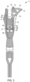
- FIG. 7 is a cross-sectional view of the latch of FIG. 1 , taken along line 4 - 4 while the latch is in the closed configuration.
- FIG. 8 is an isometric exploded view of the internal components of FIG. 2 .
- FIG. 9 is an isometric view of a second embodiment of a latch in accordance with the principles of the present invention.
- FIG. 10 is a side elevational view of the latch of FIG. 9 .
- FIG. 11 is a cross-sectional view of the latch of FIG. 9 , taken along the line 11 - 11 in FIG. 10 while the latch is in an open configuration.
- FIG. 12 is a front elevational view of the latch of FIG. 9 .
- FIG. 13 is a rear elevational view of the latch of FIG. 9 .
- FIG. 14 is a cross-sectional view of the latch of FIG. 9 , taken along the line 14 - 14 in FIG. 12 while the latch is in the open configuration.
- FIG. 15 is a cross-sectional view of the latch of FIG. 9 , taken along the line 13 - 13 in FIG. 10 while the latch is in a closed configuration.
- FIG. 16 is a cross-sectional view of the latch of FIG. 9 , taken along the line 14 - 14 in FIG. 12 while the latch is in the closed configuration.
- FIG. 17 is an isometric view of a fourth embodiment of a latch in an open configuration in accordance with the principles of the present invention.
- FIG. 18 is an isometric view of the latch of FIG. 17 in a closed configuration.
- FIG. 19 is an isometric view of internals of the latch of FIG. 17 in the open configuration.
- FIG. 20 is an isometric view of internals of the latch of FIG. 17 in the closed configuration.
- a latch in accordance with the principles of the invention is generally indicated at reference number 2 in the various figures of the attached drawings wherein numbered elements in the figures correspond to like numbered elements herein.
- FIG. 1 shows the latch 2 that includes a distal latch coupler 4 that is configured to receive, latch, and selectively release a latchable member 6 (for example, an O-ring, a D-ring, or a bar) to be secured in the latch coupler 4 .
- the latch coupler 4 is swivel-coupled to a proximal coupler 8 that is configured to couple to a proximal member 10 (for example, a leash, helmet chin strap, or tie-down strap).
- a proximal member 10 for example, a leash, helmet chin strap, or tie-down strap
- the latchable member 6 is configured to be coupled to or is a component of a device that a user desires to secure to the proximal member 10 (for example, a dog collar such as a choker collar, another helmet chin strap, or another tie-down strap). Accordingly, the latch coupler 4 facilitates releasably coupling the latchable member 6 to the proximal member 10 .
- FIG. 2 shows components of the latch 2 that are internal to or coupled to the housing 12 shown in FIG. 1 .
- the latch 2 has a trigger 14 that is configured to retain a closed-biased catch 16 in an open configuration as shown in FIGS. 1 - 5 until the latchable member 6 actuates the trigger 14 by transitioning the trigger 14 to the actuated configuration shown in FIGS. 6 and 7 .
- Actuating the trigger 14 releases the catch 16 , thereby enabling the catch 16 to move in accordance with its bias toward a closed configuration as shown in FIGS. 6 and 7 to facilitate automatically securing the latchable member 6 in the latch 2 .
- the latch 2 facilitates releasably coupling the latchable member 6 to the proximal member 10 with single-handed operation because the user only needs to insert the latchable member 6 into the latch 2 with sufficient force to actuate the trigger 14 .
- the latch 2 has a magnet 18 that is configured to attract the latchable member 6 with a force sufficient to actuate the trigger 14 , thereby further automating securing the latchable member 6 in the latch 2 responsive to the user placing the latchable member 6 in the latch 2 .
- the trigger 14 is biased toward a retaining configuration as shown in FIGS. 2 - 5 in which the trigger 14 retains the catch 16 in the open configuration.
- the magnitude of the retaining-bias force is defined by a bias member 20 (for example, a compression spring such as a coil spring).
- the magnet 18 is selected such that, at least at the distance 32 (see FIG.
- the latch 2 facilitates releasably coupling the latchable member 6 to the proximal member 10 with single-handed operation because, in some embodiments, the user only needs to insert the latchable member 6 into the latch 2 a sufficient distance for the magnet 18 to attract the latchable member 6 with sufficient force to actuate the trigger 14 .
- the magnetic-attraction force exceeds the retaining-bias force when the latchable member 6 is within 0.5, 1, 1.5, 2, 2.5, or 3 millimeters of the magnet 18 . In some embodiments, the magnetic-attraction force exceeds the retaining-bias force when the latchable member 6 is within 0.25, 0.5, 0.75, or 1 times the cross-sectional diameter of the wire or bar section of the latchable member 6 .
- the latchable member 6 may be an O-ring with an outer diameter of 15, 20, 25, or 30 mm, and the cross-sectional diameter of the bar that defines the O-ring may be 3, 4, or 5 mm.
- the latchable member 6 (or at least a portion of the latchable member 6 ) preferably includes a ferrous metal.
- the latchable member may also include a magnet with its pole oriented to be attracted to the latch magnet 18 .
- the magnet 18 held within the latch may include multiple magnets stacked in series (for example, on top of each other with their poles similarly oriented) or disposed in parallel to each other (for example, side-by-side to each other with their poles similarly oriented).
- the magnet 18 provides approximately 10-12 pounds of force to the latchable member 6 if in contact with the latchable member 6 .
- the magnet 18 has a volume of approximately 900 cubic millimeters, preferably between 500 cubic mm and 2000 cubic mm.
- the magnet 18 includes a rare-earth magnet.
- the magnet 18 is directly exposed to the latchable member 6 .
- magnetically translucent material for example, plastic
- epoxy or another material may be coated on the magnet 18 to prevent direct contact with the latchable member 6 .
- the latch 4 is also configured to facilitate simple release of the latchable member 6 and to also facilitate automatically resetting the trigger upon releasing or moving the latchable member 6 .
- the catch 16 in the closed configuration prevents the trigger 14 from returning to the retaining configuration until the secured latchable member 6 is released.
- the secured latchable member 6 or the catch 16 blocks the path of the trigger 14 to prevent the trigger 14 from returning to the retaining configuration while the catch 16 is in the closed configuration.
- the user moves the catch 16 in the direction opposite its bias and back into the open configuration (contrast the closed configuration of FIGS. 6 and 7 with the open configuration of FIGS. 1 - 5 ).
- the latchable member 6 With the catch 16 in the open configuration, the latchable member 6 is released and thus able to be removed from the latch 2 .
- the force of the magnetic attraction of the latchable member 6 exceeds the retaining-bias force of the trigger, the user pulls the released latchable member 6 away from the magnet 18 , thereby freeing the retaining-bias of the trigger 14 to move the trigger back into the retaining configuration.
- the retaining-bias of the trigger 14 can move the trigger back into the retaining configuration without the user contacting the latchable member 6 . Accordingly, the trigger 14 automatically reengages and retains the catch 16 upon releasing or moving the latchable member 6 , thereby facilitating automatic preparation of the latch 2 for re-use.
- the latch 2 includes a housing 21 that defines a receiver channel 22 that is configured to receive the latchable member 6 .
- the channel 22 is open on three sides. In other embodiments, the channel 22 is closed on five sides and open on only the side opposite the trigger 14 or the magnet 18 . The end portion of the channel 22 that is opposite the trigger 14 or the magnet 18 is ramped or outwardly flared to facilitate guiding the latchable member 6 into the latch 2 .
- the latchable member 6 is secured in the channel 22 by the catch 16 and the walls of the channel 22 (see FIGS. 6 and 7 ).
- the catch 16 and another portion of the latch 2 such as the housing 21 are configured to cooperatively prevent the catch 16 from moving beyond the closed configuration.
- the path through which the catch 16 travels is restrained such that the catch 16 cannot continue its path beyond the closed configuration.
- the housing 21 defines a catch limiter 23 that is configured to contact the catch 16 in the closed configuration and prevent the catch 16 from moving beyond the closed configuration (see FIG. 6 ).
- the catch limiter 23 includes a female member such as a recess in a wall of the channel 22
- the catch limiter 23 includes a male member such as a protrusion from the wall of the channel 22 toward a central axis of the channel 22 .
- a flat wall of the channel defines the catch limiter 23 without a variation in the plane of the wall (see, for example, FIG. 16 ).
- the features that prevent the catch 16 from traveling beyond the closed configuration can be configured to fail once a threshold force is applied to the latchable member 6 in a direction away from the trigger 14 and through the catch 16 (for example, approximately 100 pounds), thereby providing safety in the event of an accident such as a dog being caught in an elevator while the leash extends out of shut elevator doors.
- the housing 21 or the catch 16 are configured to elastically deform and thus only temporarily fail upon such threshold being reached.
- the housing 21 or the catch 16 may include nylon.
- the trigger 14 has a base portion 34 and two opposing extension portions 36 , 38 that extend from the base portion 34 to define generally a U-shape.
- the base portion 34 defines a surface for the biasing member 20 to press and thereby bias the trigger 14 toward the retaining configuration.
- the base portion 34 has a biasing-member alignment member 40 that is configured to prevent the biasing member 20 from becoming misaligned in the latch 2 .
- the alignment member 40 includes a male protrusion that is received by the biasing member 20 , and in other embodiments, the alignment member 40 includes a female member such as a recess that receives the biasing member 20 .
- the extension portions 36 , 38 have respective throw limiters 42 , 44 that are configured to limit the throw of the trigger 14 toward and away from the retaining configuration.
- the throw limiters 42 , 44 include female members such as slots that facilitate receiving a fixed male member 46 such as a pin, and in other embodiments, the throw limiters 42 , 44 include male protrusions that are received by female members in the housing 21 of the latch 2 (see the housing 21 in FIG. 1 ).
- the extension portions 36 , 38 have retaining arms 62 , 64 that are configured to engage and retain the catch 16 when the trigger 14 is in the retaining configuration.
- the extension portions 36 , 38 also have actuating portions 66 , 68 that are configured to contact the latchable member 6 when it is received by the latch 2 and to transfer the force from the latchable member 6 to the remainder of the trigger 14 , whereby such force is transferred to the biasing member 20 and thereby actuates the trigger 14 .
- the catch 14 has a catching portion 70 and a finger-engagement portion 72 .
- the catching portion 70 is configured to trap the latchable member 6 in the latch 2 when the catch 16 is in the closed configuration (see FIGS. 6 and 7 ).
- the catching portion 70 is smooth and convex to facilitate easily transitioning the catch 16 from the closed configuration to the open configuration, and in other embodiments, the catching portion 70 includes a recess that is configured to prevent transitioning the catch 16 from the closed configuration to the open configuration until the user presses the latchable member 6 farther into the latch 2 to remove the latchable member 6 from such recess.
- the finger-engagement portion 72 is configured to transition the catch 16 to the open configuration (see FIGS. 1 - 5 ) when moved by a user's finger (or another device such as a pin).
- the catch 14 is configured to pivot about a pin 74 (see FIGS. 1 - 3 , 6 , and 8 ), and a biasing member 76 (see FIGS. 2 and 8 ) biases the catch 16 to move toward the closed configuration (see FIGS. 6 and 7 ).
- the biasing member 76 is a torsion spring that is configured to have one end portion 80 received in a recess 78 defined by the catch 16 (see FIG. 8 ) while the other end portion 92 presses against the housing 21 to bias the catch 14 .
- the latch housing 21 has a biasing-member alignment member 92 that is configured to prevent the biasing member 20 from becoming misaligned in the latch 2 .
- the alignment member 92 includes a female member where the housing 21 defines a recess 94 and protrusions (for example, the protrusion 96 shown in FIGS. 3 and 6 ) on outer sides of the biasing member 20 , and in other embodiments, the alignment member 92 includes a male member such as a protrusion that is received in the biasing member 20 .
- a swivel coupler 98 pivotally couples the latch coupler 4 to the proximal coupler 8 .
- the swivel coupler 98 includes a male rod 100 (for example, a clevis pin) and a female tube 102 (for example, a hollow clevis pin having an inner diameter that is at least as large as the outer diameter of the male rod 100 ) that is configured to receive the male tube 100 .
- FIGS. 2 and 8 show the female tube 102 separately from the housing 21 for ease of understanding, the housing 21 preferably defines the female tube 102 . As shown in FIG.
- the male rod 100 is longer than the female tube 102 such that, when a flange 104 of the male rod 100 is received by a recess 106 disposed at one end portion of the female tube 102 , a grooved portion 108 of the male rod 100 extends out the opposite end portion of the female tube 102 .
- the grooved portion 108 of the male rod 100 is configured to receive a tube-retaining member 110 such as a C-clip or an E-clip after the grooved portion 108 extends through the female tube 102 , thereby retaining the male rod 100 in the female tube 102 .
- a washer 122 is placed on the female tube 102 , and a washer-retaining member 124 such as an E-clip or a C-clip is coupled to the female tube 102 such as in a groove 126 at the end portion of the female tube 102 that is opposite the flange 106 .
- the swivel coupler 98 facilitates pivotally clamping the housing 21 of the latch coupler 4 to the proximal coupler 8 between the flange 106 of the female tube 102 and the washer 122 .
- Some embodiments do not include the swivel coupler 98 , but clamp without the added swivel.
- FIGS. 9 - 16 show a second embodiment of a latch 202 in accordance with the principles of the invention.
- the latch 202 includes a latch coupler 204 is configured to receive, latch, and selectively release a latchable member (for example, an O-ring, a D-ring, or a bar) (see FIGS. 15 and 16 ) to be secured in the latch coupler 204 .
- the latch coupler 204 is fixedly coupled to a proximal coupler 206 that is configured to couple to a proximal member (for example, a leash, helmet chin strap, or tie-down strap) (not shown).
- a proximal member for example, a leash, helmet chin strap, or tie-down strap
- the latchable member is configured to be coupled to or is a component of a device that a user desires to secure to the proximal member (for example, a dog collar such as a choker collar, another helmet chin strap, or a tie-down strap). Accordingly, the latch 202 facilitates releasably coupling the latchable member to the proximal member.
- a dog collar such as a choker collar, another helmet chin strap, or a tie-down strap
- the latch 202 is configured to automatically secure the latchable member in the latch 202 responsive to receiving the latchable member.
- the latch 202 has a trigger 208 that is configured to retain a closed-biased catch 210 in an open configuration as shown in FIGS. 9 - 12 and 14 until the latchable member actuates the trigger 208 by moving it to the actuated configuration shown in FIGS. 15 and 16 .
- the trigger 208 is defined by a pivoting member rather than a translating member.
- the latch 202 has a housing 212 that defines a receiver channel 214 that is configured to receive the latchable member.
- the trigger 208 is configured to pivot about or with a male member 216 such as a pin that is disposed opposite the channel 214 from the catch 210 in the closed configuration.
- the trigger 208 defines male members that extend into female members to facilitate the trigger 208 pivoting in such female members.
- the trigger 208 extends from the pivot point defined by the male member 216 through the housing 212 and the channel 214 to the external side of the housing 212 that is opposite the channel 214 from the pivot point defined by the male member 216 .
- the portions of the trigger 208 that are disposed in the channel 214 define respective actuating portions 218 , 220 (see FIG. 10 for the actuating portion 218 and FIGS. 9 and 14 for the actuating portion 220 ).
- the trigger 208 pivots about the pivot point defined by the male member 216 , and travels through pathways 232 , 234 , 236 , 238 (for example, slots) (see FIGS. 11 and 12 ) defined in the housing 212 .
- the trigger 208 defines a retaining arm 240 external to the housing 212 and opposite the channel 214 from the pivot point defined by the male member 216 .
- the trigger 208 is biased toward the retaining configuration shown in FIGS. 9 - 14 by a biasing member (for example, a compression spring or a torsion spring) (not shown).
- the catch 210 is biased toward the closed configuration shown in FIGS. 15 and 16 .
- the retaining arm 240 in the retaining configuration retains the catch 210 in the open configuration shown in FIGS. 9 - 14 .
- the catch 210 defines a recess 242 that is configured to receive the retaining arm 240 .
- the trigger 208 pivots and displaces the retaining arm 240 , thereby permitting the catch 210 to travel to the closed configuration, such as by pivoting about a pivot point defined by a male member 244 such as a pin.
- the catch 210 defines male members that extend into female members of the housing 212 to facilitate the catch 210 pivoting in such female members. In the closed configuration, the catch 210 contacts the wall of the channel 214 that is opposite the pivot point defined by the male member 244 , thereby securing the latchable member in the latch 202 .
- the distance between the actuating portions 218 , 220 and the retaining arm 240 in combination with the pivoting action of the trigger 208 provides a mechanical advantage and facilitates increased throw at the retaining arm 240 .
- the pivoting of the retaining arm 240 compared with translation of other triggers facilitates increased robustness and reduced concern over smoothness of inner surfaces, tolerances, and misaligned components.
- the catch 210 has a finger-engagement portion 246 that enables the user to move the catch 210 from the closed configuration to the open configuration by pressing the member 246 and thereby pivoting the catch about the pivot point defined by the member 244 .
- the retaining arm 240 aligns with the recess 242 , and the retaining bias of the trigger 208 moves the retaining arm 240 back into engagement with the recess 242 of the catch 210 , thereby retaining the catch 210 until the next insertion of the latchable member.
- FIG. 17 shows a fourth embodiment of a latch 402 in accordance with the principles of the invention.
- the latch 402 includes a latch coupler 404 is configured to receive, latch, and selectively release a latchable member 406 (for example, a flange end portion of a bar) to be secured in the latch coupler 404 .
- the proximal end portion 408 of the latch coupler 404 is configured to couple to a proximal coupler (not shown) that is configured to couple to a proximal member (for example, a leash, helmet chin strap, mounting bracket, or tie-down strap) (not shown).
- the latchable member 406 is configured to be coupled to or is a component of a device that a user desires to secure to the proximal member (for example, a dog collar such as a choker collar, another helmet chin strap, or a tie-down strap). Accordingly, the latch 402 facilitates releasably coupling the latchable member to the proximal member.
- a dog collar such as a choker collar, another helmet chin strap, or a tie-down strap
- the latch 402 has a catch 410 that is biased toward the closed configuration shown in FIGS. 18 and 20 by a biasing member.
- FIGS. 19 and 20 show internal components of catch 410 , such as the biasing member including a pair of coil springs 412 , 414 that press against an internal surface of the latch coupler 404 .
- the latch 402 includes a trigger 416 that biased toward a retaining configuration and is configured to retain the closed-biased catch 410 in the open configuration as shown in FIGS. 17 and 19 until the latchable member 406 actuates the trigger 416 by moving it to the actuated configuration shown in FIG. 20 .
- the catch 410 pivots about axes that are parallel to the direction that the trigger 416 translates, rather than substantially perpendicular to it.
- the trigger 416 has two opposite retaining arms 418 , 420 coupled to each other through a base portion 432 . Also extending from the base portion is an actuating portion 434 .
- the latch 402 has a magnet 436 fixedly coupled to the housing 437 of the latch 402 (housing shown in FIGS. 20 and 21 ) to facilitate automatic latching of the latchable member 406 .
- the latch 402 lacks such magnet 436 .
- the actuating portion 434 is configured to extend away from the base by a sufficient distance that, in the retaining configuration shown in FIG.
- the actuating portion 434 extends farther from the base portion 432 than the magnet 436 by at least the amount that the retaining arms 416 , 418 overlap the paths of the retained portions of the catch 410 to facilitate the latchable member 406 translating the trigger 416 by a sufficient distance to release the catch 410 from the open configuration (contrast FIGS. 22 and 23 ).
- the actuating portion 434 is disposed adjacent to the magnet 436 , the actuating portion 434 being constrained in a channel to guide the trigger 416 along translational movement and avoid tipping.
- the actuating portion 434 may be coaxial with the trigger's biasing member.
- the catch 410 includes a pair of pivoting arms 438 , 440 that have respective catching portions 442 , 444 (see FIGS. 19 and 20 ) and respective finger-engagement portions 446 , 448 (see FIGS. 17 and 18 ).
- the catching portions 442 , 444 are configured to cooperatively trap the flange end portion 450 of the latchable member 406 when the catch 410 is in the closed configuration (see FIGS. 18 and 20 ).
- the finger-engagement portions 446 , 448 are configured to transition the respective pivoting arms 438 , 440 to the open configuration (see FIGS. 17 and 19 ) when moved (for example, pinched together) by a user.
- the pivoting arms 438 , 440 are configured to pivot about respective pins 462 , 464 .
- the biasing members 412 , 414 bias the catch 410 toward the closed configuration
- the biasing member 466 biases the trigger 416 toward the retaining configuration. Accordingly, when the user pinches together the finger-engagement portions 446 , 448 to transition the catch 410 into the open configuration (and, in embodiments with the magnet 436 , the latchable member 406 is pulled away from the magnet 436 ), the trigger 416 automatically reengages the catch 410 , thereby facilitating automatic preparation of the latch 402 for re-use.
- the following terms take the meanings explicitly associated herein, unless the context clearly dictates otherwise.
- the term “or” is an inclusive grammatical conjunction to indicate that one or more of the connected terms may be employed.
- the phrase “one or more A, B, or C” or the phrase “one or more As, Bs, or Cs” is employed to discretely disclose each of the following: i) one or more As, ii) one or more Bs, iii) one or more Cs, iv) one or more As and one or more Bs, v) one or more As and one or more Cs, vi) one or more Bs and one or more Cs, and vii) one or more As, one or more Bs, and one or more Cs.
- the term “configured” refers to an element being one or more of sized, dimensioned, positioned, or oriented to achieve or provide the recited function or result.
- the term “substantially parallel” or “similarly oriented” refers to parallel or within 5, 10, 15, 20, 25, 30, 35, 40, or 45 degrees of parallel.
- the term “substantially perpendicular” refers to perpendicular or within 5, 10, 15, 20, 25, 30, 35, 40, or 45 degrees of perpendicular.
- the term “approximately” refers to the recited value or range of values or within 5, 10, 15, 20, 25, 30, 35, 40, 45, or 50 percent of such value or a value in such range of values.
- the term “transverse” means non-parallel but not necessarily crossing.
- directly coupled refers to a component that contacts (for example, when bolted), is integral with, or is welded to another component.
- indirectly coupled refers to a component that is coupled to one or more other components that are coupled to a second component or one or more further components that are coupled to the second component.
- coupled should be understood to disclose both direct and indirect coupling of components or elements that are described as being coupled to each other, and different embodiments may be directly coupled or indirectly coupled.
- the use of the term “responsive to” does not imply that associated resultant actions are required to occur immediately or within a particular time period; instead, the term “responsive to” is used herein to indicate actions that may occur or be performed in response to one or more conditions being met, unless the context clearly dictates otherwise.
- the use of “when” does not imply that associated actions are a result of a condition or that the actions are required to occur immediately or within a particular time period; instead, the term “when” is used herein to indicate actions that may occur or be performed at least at a recited moment in time.
Landscapes
- Life Sciences & Earth Sciences (AREA)
- Environmental Sciences (AREA)
- Animal Husbandry (AREA)
- Biodiversity & Conservation Biology (AREA)
- Helmets And Other Head Coverings (AREA)
- Buckles (AREA)
- Purses, Travelling Bags, Baskets, Or Suitcases (AREA)
Abstract
Description
Claims (19)
Priority Applications (2)
| Application Number | Priority Date | Filing Date | Title |
|---|---|---|---|
| US17/351,106 US12127635B2 (en) | 2020-06-18 | 2021-06-17 | Magnetically guided latch |
| US18/760,010 US20240349699A1 (en) | 2020-06-18 | 2024-06-30 | Coupler orientation system |
Applications Claiming Priority (2)
| Application Number | Priority Date | Filing Date | Title |
|---|---|---|---|
| US202063040752P | 2020-06-18 | 2020-06-18 | |
| US17/351,106 US12127635B2 (en) | 2020-06-18 | 2021-06-17 | Magnetically guided latch |
Related Child Applications (1)
| Application Number | Title | Priority Date | Filing Date |
|---|---|---|---|
| US18/760,010 Continuation-In-Part US20240349699A1 (en) | 2020-06-18 | 2024-06-30 | Coupler orientation system |
Publications (2)
| Publication Number | Publication Date |
|---|---|
| US20210392856A1 US20210392856A1 (en) | 2021-12-23 |
| US12127635B2 true US12127635B2 (en) | 2024-10-29 |
Family
ID=77168375
Family Applications (1)
| Application Number | Title | Priority Date | Filing Date |
|---|---|---|---|
| US17/351,106 Active 2041-09-26 US12127635B2 (en) | 2020-06-18 | 2021-06-17 | Magnetically guided latch |
Country Status (3)
| Country | Link |
|---|---|
| US (1) | US12127635B2 (en) |
| EP (1) | EP4167793B1 (en) |
| WO (1) | WO2021257912A1 (en) |
Families Citing this family (2)
| Publication number | Priority date | Publication date | Assignee | Title |
|---|---|---|---|---|
| GB2604395B (en) * | 2021-03-05 | 2023-07-26 | Paul Simon Rawlings | Connector |
| US12193410B1 (en) * | 2023-08-23 | 2025-01-14 | Pilot Dogs, Inc | Harness system for use with an animal |
Citations (104)
| Publication number | Priority date | Publication date | Assignee | Title |
|---|---|---|---|---|
| US2475226A (en) | 1945-02-01 | 1949-07-05 | Robert P Ellis | Magnetic fastener |
| US3623194A (en) * | 1968-12-19 | 1971-11-30 | Goeteborga Bandvaeveri | Quick release coupling particularly for safety harnesses for cars |
| US4416037A (en) * | 1980-07-11 | 1983-11-22 | Tetra Werke Dr. Rer. Nat. Ulrich Baensch Gmbh | Releasable connector in leashes for domestic animal, safety line or the like |
| US5329883A (en) * | 1994-01-18 | 1994-07-19 | White James R | Releasable hitch |
| US5752299A (en) * | 1996-05-06 | 1998-05-19 | Alliedsignal Inc. | Seat belt buckle with usage indicator |
| US5839174A (en) * | 1997-06-13 | 1998-11-24 | Breed Automotive Technology, Inc. | Seat belt buckle |
| US5898366A (en) * | 1997-09-23 | 1999-04-27 | Trw Vehicle Safety Systems Inc. | Seat belt buckle with Hall effect locking indicator |
| US5934599A (en) | 1997-08-22 | 1999-08-10 | Hammerslag; Gary R. | Footwear lacing system |
| JP2001221375A (en) | 1995-10-03 | 2001-08-17 | Hitachi Metals Ltd | Magnetic hanging device |
| US6289558B1 (en) | 1997-08-22 | 2001-09-18 | Boa Technology, Inc. | Footwear lacing system |
| US6381815B1 (en) * | 1999-09-21 | 2002-05-07 | Takata Corporation | Buckle with non-contact switch |
| US6499437B1 (en) | 2001-08-15 | 2002-12-31 | Joseph A. Sorensen | Magnetic connector |
| US20030101553A1 (en) * | 2001-10-29 | 2003-06-05 | Kabushiki Kaisha Tokai-Rika-Denki-Seisakusho | Buckle apparatus |
| US6671933B1 (en) * | 2002-04-29 | 2004-01-06 | Roxane Friend | Safety coupler with release mechanism |
| US20050139739A1 (en) | 2003-12-31 | 2005-06-30 | Hamerski Michael D. | Magnetic-adhesive mounting device |
| FR2830264B1 (en) | 2001-09-28 | 2005-10-14 | Devanlay Sa | DEVICE FOR MAINTAINING AND TENSIONING A PIECE OF FLEXIBLE MATERIAL |
| US7145425B2 (en) | 2005-01-07 | 2006-12-05 | Joe Raymond Clement | Magnetic securement device magnetically attached to a sheetrock fastener |
| JP2007068828A (en) | 2005-09-08 | 2007-03-22 | Motoyuki Fujiwara | Article supporting appliance |
| US20070084026A1 (en) * | 2005-10-19 | 2007-04-19 | Kabushiki Kaisha Tokai-Rika- Denki-Seisakusho | Buckle device |
| US20070099469A1 (en) | 2005-11-03 | 2007-05-03 | Nite Ize, Inc. | General purpose magnetic connector |
| US20070204442A1 (en) * | 2005-07-05 | 2007-09-06 | Falb Margo B | Seat belt buckle |
| US7591050B2 (en) | 1997-08-22 | 2009-09-22 | Boa Technology, Inc. | Footwear lacing system |
| CN101782101A (en) | 2010-01-25 | 2010-07-21 | 陈奇康 | Fixing device made from magnet and resin adhesive |
| US7950112B2 (en) | 1997-08-22 | 2011-05-31 | Boa Technology, Inc. | Reel based closure system |
| US7954204B2 (en) | 1997-08-22 | 2011-06-07 | Boa Technology, Inc. | Reel based closure system |
| CN102098937A (en) | 2008-07-17 | 2011-06-15 | 费得洛克有限公司 | Shielded magnetic plug-in lock |
| US8042235B2 (en) * | 2009-05-26 | 2011-10-25 | Taiwan Racing Products Co., Ltd. | Buckling device for safety belt |
| US20110298227A1 (en) | 2009-01-23 | 2011-12-08 | Fidlock Gmbh | Closure Device for Connecting Two Parts |
| DE202011052397U1 (en) | 2011-12-21 | 2012-01-17 | Fidlock Gmbh | closure device |
| WO2012036813A1 (en) | 2010-09-14 | 2012-03-22 | Mitchell Lucy A | Hook with magnetic closure |
| US20120124786A1 (en) | 2010-11-18 | 2012-05-24 | Fidlock Gmbh | Locking Device |
| FR2972361A1 (en) | 2011-03-09 | 2012-09-14 | Soream | Snap hook for safety harness of user in hostile environment, has sensor acting on associated pawl to bring pawl to unlocked position to allow pivoting of snap to open position when lifeline is detected |
| US8277401B2 (en) | 2006-09-12 | 2012-10-02 | Boa Technology, Inc. | Closure system for braces, protective wear and similar articles |
| US8368494B2 (en) | 2007-12-04 | 2013-02-05 | FIDLOCK, GmbH | Magnetic coupling device |
| US8381362B2 (en) | 2004-10-29 | 2013-02-26 | Boa Technology, Inc. | Reel based closure system |
| US8424168B2 (en) | 2008-01-18 | 2013-04-23 | Boa Technology, Inc. | Closure system |
| US8468657B2 (en) | 2008-11-21 | 2013-06-25 | Boa Technology, Inc. | Reel based lacing system |
| US8474108B2 (en) | 2010-09-22 | 2013-07-02 | Harald Eisenberger | Clasp held by opposing magnetic forces |
| US8516662B2 (en) | 2010-04-30 | 2013-08-27 | Boa Technology, Inc. | Reel based lacing system |
| US20130221173A1 (en) | 2012-02-28 | 2013-08-29 | John Ellis Glover | Magnetic hanging apparatus |
| USD691879S1 (en) | 2011-10-17 | 2013-10-22 | Robina Bernard | Magnetic fastener |
| US8713820B2 (en) | 2010-01-21 | 2014-05-06 | Boa Technology, Inc. | Guides for lacing systems |
| US20140250639A1 (en) * | 2013-03-05 | 2014-09-11 | Greg Siwak | Magnetic coupler |
| US20140298630A1 (en) * | 2013-04-09 | 2014-10-09 | Aba Hortnagl Gmbh | Buckle parts of a belt buckle |
| US9038251B1 (en) * | 2013-10-02 | 2015-05-26 | National Molding, Llc. | Quick release buckle |
| US9101181B2 (en) | 2011-10-13 | 2015-08-11 | Boa Technology Inc. | Reel-based lacing system |
| US9149089B2 (en) | 2010-07-01 | 2015-10-06 | Boa Technology, Inc. | Lace guide |
| US9179729B2 (en) | 2012-03-13 | 2015-11-10 | Boa Technology, Inc. | Tightening systems |
| US9248040B2 (en) | 2012-08-31 | 2016-02-02 | Boa Technology Inc. | Motorized tensioning system for medical braces and devices |
| US9261726B2 (en) | 2013-01-25 | 2016-02-16 | BOA Technology Group Co., Ltd. | Photoelectric sensor and photoelectric touch panel |
| WO2016029844A1 (en) | 2014-08-28 | 2016-03-03 | 陈祈勋 | Lacing fastening mechanism |
| USD751281S1 (en) | 2014-08-12 | 2016-03-15 | Boa Technology, Inc. | Footwear tightening reels |
| USD755496S1 (en) | 2014-12-24 | 2016-05-10 | Taylor Made Golf Company, Inc. | Golf shoe |
| USD758061S1 (en) | 2014-09-08 | 2016-06-07 | Boa Technology, Inc. | Lace tightening device |
| US9375053B2 (en) | 2012-03-15 | 2016-06-28 | Boa Technology, Inc. | Tightening mechanisms and applications including the same |
| US9439477B2 (en) | 2013-01-28 | 2016-09-13 | Boa Technology Inc. | Lace fixation assembly and system |
| USD767269S1 (en) | 2014-08-26 | 2016-09-27 | Boa Technology Inc. | Footwear tightening reel |
| US9486039B2 (en) | 2012-12-17 | 2016-11-08 | Shinkyung Inc | Wire clamping device |
| US9516923B2 (en) | 2012-11-02 | 2016-12-13 | Boa Technology Inc. | Coupling members for closure devices and systems |
| US9532626B2 (en) | 2013-04-01 | 2017-01-03 | Boa Technology, Inc. | Methods and devices for retrofitting footwear to include a reel based closure system |
| USD776421S1 (en) | 2015-01-16 | 2017-01-17 | Boa Technology, Inc. | In-footwear lace tightening reel |
| US9581292B2 (en) | 2015-06-17 | 2017-02-28 | Hang Em Up Inc. | Magnetic surface mounting apparatus |
| US9610185B2 (en) | 2013-03-05 | 2017-04-04 | Boa Technology Inc. | Systems, methods, and devices for automatic closure of medical devices |
| US9629417B2 (en) | 2013-07-02 | 2017-04-25 | Boa Technology Inc. | Tension limiting mechanisms for closure devices and methods therefor |
| KR20170055454A (en) | 2017-04-28 | 2017-05-19 | 주식회사 신경 | Cover Replaceable Wire Fastener |
| US9680131B2 (en) | 2014-04-24 | 2017-06-13 | Boe Technology Group Co., Ltd. | Organic light-emitting diode (OLED) panel, manufacturing method thereof and display device |
| US9681705B2 (en) | 2013-09-13 | 2017-06-20 | Boa Technology Inc. | Failure compensating lace tension devices and methods |
| US9700101B2 (en) | 2013-09-05 | 2017-07-11 | Boa Technology Inc. | Guides and components for closure systems and methods therefor |
| US9706814B2 (en) | 2013-07-10 | 2017-07-18 | Boa Technology Inc. | Closure devices including incremental release mechanisms and methods therefor |
| USD794316S1 (en) | 2015-05-18 | 2017-08-15 | Taylor Made Golf Company, Inc. | Golf shoe |
| US9737115B2 (en) | 2012-11-06 | 2017-08-22 | Boa Technology Inc. | Devices and methods for adjusting the fit of footwear |
| US9770955B2 (en) | 2014-09-23 | 2017-09-26 | Wen-chun Su | Lock for securing trailer hitch |
| US9771159B1 (en) * | 2015-11-19 | 2017-09-26 | The United States Of America As Represented By The Secretary Of The Army | Multi-ring mechanical release with side activation |
| US9770070B2 (en) | 2013-06-05 | 2017-09-26 | Boa Technology Inc. | Integrated closure device components and methods |
| US9797432B2 (en) | 2015-05-22 | 2017-10-24 | Thanasit Inkavesvaanit | Systems and methods for providing a quick-release carabiner |
| US9872568B2 (en) | 2014-02-11 | 2018-01-23 | Boa Technology Inc. | Closure devices for seat cushions |
| US9872790B2 (en) | 2013-11-18 | 2018-01-23 | Boa Technology Inc. | Methods and devices for providing automatic closure of prosthetics and orthotics |
| WO2018039584A1 (en) | 2016-08-26 | 2018-03-01 | 3M Innovative Properties Company | Adhesive mounting devices |
| US9918865B2 (en) | 2010-07-01 | 2018-03-20 | 3M Innovative Properties Company | Braces using lacing systems |
| US20180094466A1 (en) | 2016-09-30 | 2018-04-05 | Barrette Outdoor Living, Inc. | Magnetic safety gate latch |
| DE102016122879A1 (en) | 2016-11-28 | 2018-05-30 | Karl Simon Gmbh & Co. Kg | magnetic closure |
| US20180160775A1 (en) | 2016-12-09 | 2018-06-14 | Boa Technology Inc. | Reel based closure system |
| US10004297B2 (en) | 2015-10-15 | 2018-06-26 | Boa Technology Inc. | Lacing configurations for footwear |
| JP2018130940A (en) | 2017-02-17 | 2018-08-23 | 紫朗 高梨 | Rivet and connecting piece |
| US20180249682A1 (en) | 2017-03-06 | 2018-09-06 | Michael W. Brian | Leash Attachment System for Dog Collar or Harness |
| US10070695B2 (en) | 2010-04-30 | 2018-09-11 | Boa Technology Inc. | Tightening mechanisms and applications including the same |
| US10076160B2 (en) | 2013-06-05 | 2018-09-18 | Boa Technology Inc. | Integrated closure device components and methods |
| US20180310671A1 (en) | 2014-08-13 | 2018-11-01 | Boa Technology Inc. | Closure system and/or shoe configurations for enhancing the performance of running shoes |
| USD835976S1 (en) | 2014-01-16 | 2018-12-18 | Boa Technology Inc. | Coupling member |
| USD835898S1 (en) | 2015-01-16 | 2018-12-18 | Boa Technology Inc. | Footwear lace tightening reel stabilizer |
| US20180363328A1 (en) | 2017-06-16 | 2018-12-20 | Mayapple Baby Llc | Locking mechanism and locking body assembly for magnetic lock, and the magnetic lock |
| US10174784B1 (en) | 2011-06-08 | 2019-01-08 | Bolder Products, LLC | Bungee cord with interlocking hooks |
| US10173085B2 (en) | 2014-12-22 | 2019-01-08 | Thierry Dehondt | Carabiner and securing assembly for a safe securing system |
| US20190021447A1 (en) | 2017-07-18 | 2019-01-24 | Boa Technology Inc. | System and methods for minimizing dynamic lace movement |
| US20190024698A1 (en) | 2015-09-10 | 2019-01-24 | Easyclic Gmbh | Hook in conjunction with an element to be inserted into the hook interior |
| WO2019192930A1 (en) | 2018-04-05 | 2019-10-10 | Goleygo Gmbh | Closing device for releasably connecting a first part to a second part |
| US20200022463A1 (en) * | 2018-07-23 | 2020-01-23 | Gordon Daniel Oke Templeton | Multi-function buckle assembly |
| US11044970B1 (en) * | 2020-03-30 | 2021-06-29 | Duraflex Hong Kong Limited | Attachment system with quick release |
| US20220015484A1 (en) * | 2020-07-15 | 2022-01-20 | Scott Pagano | Multipurpose, crossbody strap with universal interlocking rings |
| US20220295948A1 (en) * | 2021-03-18 | 2022-09-22 | Wonderland Switzerland Ag | Fastener, fastener monitoring system, and child carrier |
| US20220349431A1 (en) * | 2021-04-30 | 2022-11-03 | Aspetto, Inc. | Quick-release swivel latches |
| US20230000214A1 (en) * | 2020-02-22 | 2023-01-05 | Protekt- Laszkiewicz Grzegorz | Automatic snap buckle |
| US11564457B1 (en) * | 2021-11-19 | 2023-01-31 | Taiwan Racing Products Co., Ltd. | Safety belt buckle assembly |
| US20230061741A1 (en) * | 2021-08-29 | 2023-03-02 | Make Ideas, LLC | Releasable coupling device |
-
2021
- 2021-06-17 WO PCT/US2021/037950 patent/WO2021257912A1/en not_active Ceased
- 2021-06-17 US US17/351,106 patent/US12127635B2/en active Active
- 2021-06-17 EP EP21749375.8A patent/EP4167793B1/en active Active
Patent Citations (124)
| Publication number | Priority date | Publication date | Assignee | Title |
|---|---|---|---|---|
| US2475226A (en) | 1945-02-01 | 1949-07-05 | Robert P Ellis | Magnetic fastener |
| US3623194A (en) * | 1968-12-19 | 1971-11-30 | Goeteborga Bandvaeveri | Quick release coupling particularly for safety harnesses for cars |
| US4416037A (en) * | 1980-07-11 | 1983-11-22 | Tetra Werke Dr. Rer. Nat. Ulrich Baensch Gmbh | Releasable connector in leashes for domestic animal, safety line or the like |
| US5329883A (en) * | 1994-01-18 | 1994-07-19 | White James R | Releasable hitch |
| JP2001221375A (en) | 1995-10-03 | 2001-08-17 | Hitachi Metals Ltd | Magnetic hanging device |
| US5752299A (en) * | 1996-05-06 | 1998-05-19 | Alliedsignal Inc. | Seat belt buckle with usage indicator |
| US5839174A (en) * | 1997-06-13 | 1998-11-24 | Breed Automotive Technology, Inc. | Seat belt buckle |
| US5934599A (en) | 1997-08-22 | 1999-08-10 | Hammerslag; Gary R. | Footwear lacing system |
| US6289558B1 (en) | 1997-08-22 | 2001-09-18 | Boa Technology, Inc. | Footwear lacing system |
| US9743714B2 (en) | 1997-08-22 | 2017-08-29 | Boa Technology Inc. | Reel based closure system |
| US7591050B2 (en) | 1997-08-22 | 2009-09-22 | Boa Technology, Inc. | Footwear lacing system |
| USD799810S1 (en) | 1997-08-22 | 2017-10-17 | Boa Technology Inc. | Shoe lace tightening reel |
| US9339082B2 (en) | 1997-08-22 | 2016-05-17 | Boa Technology, Inc. | Reel based closure system |
| US7992261B2 (en) | 1997-08-22 | 2011-08-09 | Boa Technology, Inc. | Reel based closure system |
| US7954204B2 (en) | 1997-08-22 | 2011-06-07 | Boa Technology, Inc. | Reel based closure system |
| US7950112B2 (en) | 1997-08-22 | 2011-05-31 | Boa Technology, Inc. | Reel based closure system |
| US5898366A (en) * | 1997-09-23 | 1999-04-27 | Trw Vehicle Safety Systems Inc. | Seat belt buckle with Hall effect locking indicator |
| US6381815B1 (en) * | 1999-09-21 | 2002-05-07 | Takata Corporation | Buckle with non-contact switch |
| US6499437B1 (en) | 2001-08-15 | 2002-12-31 | Joseph A. Sorensen | Magnetic connector |
| FR2830264B1 (en) | 2001-09-28 | 2005-10-14 | Devanlay Sa | DEVICE FOR MAINTAINING AND TENSIONING A PIECE OF FLEXIBLE MATERIAL |
| US20030101553A1 (en) * | 2001-10-29 | 2003-06-05 | Kabushiki Kaisha Tokai-Rika-Denki-Seisakusho | Buckle apparatus |
| US6671933B1 (en) * | 2002-04-29 | 2004-01-06 | Roxane Friend | Safety coupler with release mechanism |
| US9867430B2 (en) | 2003-06-12 | 2018-01-16 | Boa Technology Inc. | Reel based closure system |
| US20050139739A1 (en) | 2003-12-31 | 2005-06-30 | Hamerski Michael D. | Magnetic-adhesive mounting device |
| US8381362B2 (en) | 2004-10-29 | 2013-02-26 | Boa Technology, Inc. | Reel based closure system |
| US7145425B2 (en) | 2005-01-07 | 2006-12-05 | Joe Raymond Clement | Magnetic securement device magnetically attached to a sheetrock fastener |
| US20070204442A1 (en) * | 2005-07-05 | 2007-09-06 | Falb Margo B | Seat belt buckle |
| JP2007068828A (en) | 2005-09-08 | 2007-03-22 | Motoyuki Fujiwara | Article supporting appliance |
| US20070084026A1 (en) * | 2005-10-19 | 2007-04-19 | Kabushiki Kaisha Tokai-Rika- Denki-Seisakusho | Buckle device |
| US20070099469A1 (en) | 2005-11-03 | 2007-05-03 | Nite Ize, Inc. | General purpose magnetic connector |
| US8277401B2 (en) | 2006-09-12 | 2012-10-02 | Boa Technology, Inc. | Closure system for braces, protective wear and similar articles |
| US8368494B2 (en) | 2007-12-04 | 2013-02-05 | FIDLOCK, GmbH | Magnetic coupling device |
| US8984719B2 (en) | 2008-01-18 | 2015-03-24 | Boa Technology, Inc. | Closure system |
| US8424168B2 (en) | 2008-01-18 | 2013-04-23 | Boa Technology, Inc. | Closure system |
| US20110138583A1 (en) | 2008-07-17 | 2011-06-16 | Joachim Fiedler | Shielded Magnetic Plug-In Lock |
| CN102098937A (en) | 2008-07-17 | 2011-06-15 | 费得洛克有限公司 | Shielded magnetic plug-in lock |
| US9138030B2 (en) | 2008-11-21 | 2015-09-22 | Boa Technology Inc. | Reel based lacing system |
| US10123589B2 (en) | 2008-11-21 | 2018-11-13 | Boa Technology, Inc. | Reel based lacing system |
| US9259056B2 (en) | 2008-11-21 | 2016-02-16 | Boa Technology, Inc. | Reel based lacing system |
| US8468657B2 (en) | 2008-11-21 | 2013-06-25 | Boa Technology, Inc. | Reel based lacing system |
| US20110298227A1 (en) | 2009-01-23 | 2011-12-08 | Fidlock Gmbh | Closure Device for Connecting Two Parts |
| EP2389084B1 (en) | 2009-01-23 | 2017-05-17 | Fidlock GmbH | Closure device for connecting two parts |
| US8794682B2 (en) | 2009-01-23 | 2014-08-05 | Fidlock Gmbh | Closure device for connecting two parts |
| US8042235B2 (en) * | 2009-05-26 | 2011-10-25 | Taiwan Racing Products Co., Ltd. | Buckling device for safety belt |
| US9854873B2 (en) | 2010-01-21 | 2018-01-02 | Boa Technology Inc. | Guides for lacing systems |
| US8713820B2 (en) | 2010-01-21 | 2014-05-06 | Boa Technology, Inc. | Guides for lacing systems |
| US9125455B2 (en) | 2010-01-21 | 2015-09-08 | Boa Technology Inc. | Guides for lacing systems |
| CN101782101A (en) | 2010-01-25 | 2010-07-21 | 陈奇康 | Fixing device made from magnet and resin adhesive |
| US10070695B2 (en) | 2010-04-30 | 2018-09-11 | Boa Technology Inc. | Tightening mechanisms and applications including the same |
| US8516662B2 (en) | 2010-04-30 | 2013-08-27 | Boa Technology, Inc. | Reel based lacing system |
| US9408437B2 (en) | 2010-04-30 | 2016-08-09 | Boa Technology, Inc. | Reel based lacing system |
| US9149089B2 (en) | 2010-07-01 | 2015-10-06 | Boa Technology, Inc. | Lace guide |
| US9918865B2 (en) | 2010-07-01 | 2018-03-20 | 3M Innovative Properties Company | Braces using lacing systems |
| WO2012036813A1 (en) | 2010-09-14 | 2012-03-22 | Mitchell Lucy A | Hook with magnetic closure |
| US8474108B2 (en) | 2010-09-22 | 2013-07-02 | Harald Eisenberger | Clasp held by opposing magnetic forces |
| US20120124786A1 (en) | 2010-11-18 | 2012-05-24 | Fidlock Gmbh | Locking Device |
| DE102010044144B3 (en) | 2010-11-18 | 2012-05-31 | Fidlock Gmbh | closure device |
| US8739371B2 (en) | 2010-11-18 | 2014-06-03 | Fidlock Gmbh | Locking device |
| FR2972361A1 (en) | 2011-03-09 | 2012-09-14 | Soream | Snap hook for safety harness of user in hostile environment, has sensor acting on associated pawl to bring pawl to unlocked position to allow pivoting of snap to open position when lifeline is detected |
| US10174784B1 (en) | 2011-06-08 | 2019-01-08 | Bolder Products, LLC | Bungee cord with interlocking hooks |
| US9101181B2 (en) | 2011-10-13 | 2015-08-11 | Boa Technology Inc. | Reel-based lacing system |
| USD691879S1 (en) | 2011-10-17 | 2013-10-22 | Robina Bernard | Magnetic fastener |
| DE202011052397U1 (en) | 2011-12-21 | 2012-01-17 | Fidlock Gmbh | closure device |
| US20130221173A1 (en) | 2012-02-28 | 2013-08-29 | John Ellis Glover | Magnetic hanging apparatus |
| US9179729B2 (en) | 2012-03-13 | 2015-11-10 | Boa Technology, Inc. | Tightening systems |
| US9375053B2 (en) | 2012-03-15 | 2016-06-28 | Boa Technology, Inc. | Tightening mechanisms and applications including the same |
| US9248040B2 (en) | 2012-08-31 | 2016-02-02 | Boa Technology Inc. | Motorized tensioning system for medical braces and devices |
| US10085517B2 (en) | 2012-08-31 | 2018-10-02 | Nike, Inc. | Motorized tensioning system |
| US9516923B2 (en) | 2012-11-02 | 2016-12-13 | Boa Technology Inc. | Coupling members for closure devices and systems |
| US9737115B2 (en) | 2012-11-06 | 2017-08-22 | Boa Technology Inc. | Devices and methods for adjusting the fit of footwear |
| US9486039B2 (en) | 2012-12-17 | 2016-11-08 | Shinkyung Inc | Wire clamping device |
| US9261726B2 (en) | 2013-01-25 | 2016-02-16 | BOA Technology Group Co., Ltd. | Photoelectric sensor and photoelectric touch panel |
| US9439477B2 (en) | 2013-01-28 | 2016-09-13 | Boa Technology Inc. | Lace fixation assembly and system |
| US20140250639A1 (en) * | 2013-03-05 | 2014-09-11 | Greg Siwak | Magnetic coupler |
| US9610185B2 (en) | 2013-03-05 | 2017-04-04 | Boa Technology Inc. | Systems, methods, and devices for automatic closure of medical devices |
| US9532626B2 (en) | 2013-04-01 | 2017-01-03 | Boa Technology, Inc. | Methods and devices for retrofitting footwear to include a reel based closure system |
| US20140298630A1 (en) * | 2013-04-09 | 2014-10-09 | Aba Hortnagl Gmbh | Buckle parts of a belt buckle |
| US10076160B2 (en) | 2013-06-05 | 2018-09-18 | Boa Technology Inc. | Integrated closure device components and methods |
| US9770070B2 (en) | 2013-06-05 | 2017-09-26 | Boa Technology Inc. | Integrated closure device components and methods |
| US9629417B2 (en) | 2013-07-02 | 2017-04-25 | Boa Technology Inc. | Tension limiting mechanisms for closure devices and methods therefor |
| US10039348B2 (en) | 2013-07-02 | 2018-08-07 | Boa Technology Inc. | Tension limiting mechanisms for closure devices and methods therefor |
| US9706814B2 (en) | 2013-07-10 | 2017-07-18 | Boa Technology Inc. | Closure devices including incremental release mechanisms and methods therefor |
| US9700101B2 (en) | 2013-09-05 | 2017-07-11 | Boa Technology Inc. | Guides and components for closure systems and methods therefor |
| US9681705B2 (en) | 2013-09-13 | 2017-06-20 | Boa Technology Inc. | Failure compensating lace tension devices and methods |
| US9038251B1 (en) * | 2013-10-02 | 2015-05-26 | National Molding, Llc. | Quick release buckle |
| US9872790B2 (en) | 2013-11-18 | 2018-01-23 | Boa Technology Inc. | Methods and devices for providing automatic closure of prosthetics and orthotics |
| USD835976S1 (en) | 2014-01-16 | 2018-12-18 | Boa Technology Inc. | Coupling member |
| US9872568B2 (en) | 2014-02-11 | 2018-01-23 | Boa Technology Inc. | Closure devices for seat cushions |
| US9680131B2 (en) | 2014-04-24 | 2017-06-13 | Boe Technology Group Co., Ltd. | Organic light-emitting diode (OLED) panel, manufacturing method thereof and display device |
| USD751281S1 (en) | 2014-08-12 | 2016-03-15 | Boa Technology, Inc. | Footwear tightening reels |
| US20180310671A1 (en) | 2014-08-13 | 2018-11-01 | Boa Technology Inc. | Closure system and/or shoe configurations for enhancing the performance of running shoes |
| USD767269S1 (en) | 2014-08-26 | 2016-09-27 | Boa Technology Inc. | Footwear tightening reel |
| WO2016029844A1 (en) | 2014-08-28 | 2016-03-03 | 陈祈勋 | Lacing fastening mechanism |
| USD758061S1 (en) | 2014-09-08 | 2016-06-07 | Boa Technology, Inc. | Lace tightening device |
| US9770955B2 (en) | 2014-09-23 | 2017-09-26 | Wen-chun Su | Lock for securing trailer hitch |
| US10173085B2 (en) | 2014-12-22 | 2019-01-08 | Thierry Dehondt | Carabiner and securing assembly for a safe securing system |
| USD755496S1 (en) | 2014-12-24 | 2016-05-10 | Taylor Made Golf Company, Inc. | Golf shoe |
| USD835898S1 (en) | 2015-01-16 | 2018-12-18 | Boa Technology Inc. | Footwear lace tightening reel stabilizer |
| USD776421S1 (en) | 2015-01-16 | 2017-01-17 | Boa Technology, Inc. | In-footwear lace tightening reel |
| USD794316S1 (en) | 2015-05-18 | 2017-08-15 | Taylor Made Golf Company, Inc. | Golf shoe |
| US9797432B2 (en) | 2015-05-22 | 2017-10-24 | Thanasit Inkavesvaanit | Systems and methods for providing a quick-release carabiner |
| US9581292B2 (en) | 2015-06-17 | 2017-02-28 | Hang Em Up Inc. | Magnetic surface mounting apparatus |
| US20190024698A1 (en) | 2015-09-10 | 2019-01-24 | Easyclic Gmbh | Hook in conjunction with an element to be inserted into the hook interior |
| US10004297B2 (en) | 2015-10-15 | 2018-06-26 | Boa Technology Inc. | Lacing configurations for footwear |
| US9771159B1 (en) * | 2015-11-19 | 2017-09-26 | The United States Of America As Represented By The Secretary Of The Army | Multi-ring mechanical release with side activation |
| WO2018039584A1 (en) | 2016-08-26 | 2018-03-01 | 3M Innovative Properties Company | Adhesive mounting devices |
| US20180094466A1 (en) | 2016-09-30 | 2018-04-05 | Barrette Outdoor Living, Inc. | Magnetic safety gate latch |
| DE102016122879A1 (en) | 2016-11-28 | 2018-05-30 | Karl Simon Gmbh & Co. Kg | magnetic closure |
| US20180160775A1 (en) | 2016-12-09 | 2018-06-14 | Boa Technology Inc. | Reel based closure system |
| JP2018130940A (en) | 2017-02-17 | 2018-08-23 | 紫朗 高梨 | Rivet and connecting piece |
| US20180249682A1 (en) | 2017-03-06 | 2018-09-06 | Michael W. Brian | Leash Attachment System for Dog Collar or Harness |
| KR20170055454A (en) | 2017-04-28 | 2017-05-19 | 주식회사 신경 | Cover Replaceable Wire Fastener |
| US20180363328A1 (en) | 2017-06-16 | 2018-12-20 | Mayapple Baby Llc | Locking mechanism and locking body assembly for magnetic lock, and the magnetic lock |
| US20190021447A1 (en) | 2017-07-18 | 2019-01-24 | Boa Technology Inc. | System and methods for minimizing dynamic lace movement |
| US20210037792A1 (en) * | 2018-04-05 | 2021-02-11 | Goleygo Gmbh | Closing device for releasably connecting a first part to a second part |
| WO2019192930A1 (en) | 2018-04-05 | 2019-10-10 | Goleygo Gmbh | Closing device for releasably connecting a first part to a second part |
| US20200022463A1 (en) * | 2018-07-23 | 2020-01-23 | Gordon Daniel Oke Templeton | Multi-function buckle assembly |
| US20230000214A1 (en) * | 2020-02-22 | 2023-01-05 | Protekt- Laszkiewicz Grzegorz | Automatic snap buckle |
| US11044970B1 (en) * | 2020-03-30 | 2021-06-29 | Duraflex Hong Kong Limited | Attachment system with quick release |
| US20220015484A1 (en) * | 2020-07-15 | 2022-01-20 | Scott Pagano | Multipurpose, crossbody strap with universal interlocking rings |
| US20220295948A1 (en) * | 2021-03-18 | 2022-09-22 | Wonderland Switzerland Ag | Fastener, fastener monitoring system, and child carrier |
| US20220349431A1 (en) * | 2021-04-30 | 2022-11-03 | Aspetto, Inc. | Quick-release swivel latches |
| US20230061741A1 (en) * | 2021-08-29 | 2023-03-02 | Make Ideas, LLC | Releasable coupling device |
| US11564457B1 (en) * | 2021-11-19 | 2023-01-31 | Taiwan Racing Products Co., Ltd. | Safety belt buckle assembly |
Non-Patent Citations (2)
| Title |
|---|
| International Search Report and Written Opinion dated Oct. 22, 2021 for co-pending International Application No. PCT/US2021/037950; 13 pages. |
| The Home Depot; Lokk Latch; Black Polymer and Stainless Steel Two-way Magnetic Self-latching Fence Gate Latch 50110; Aug. 8, 2019; 4 pages. |
Also Published As
| Publication number | Publication date |
|---|---|
| EP4167793C0 (en) | 2025-12-17 |
| US20210392856A1 (en) | 2021-12-23 |
| EP4167793B1 (en) | 2025-12-17 |
| WO2021257912A1 (en) | 2021-12-23 |
| EP4167793A1 (en) | 2023-04-26 |
Similar Documents
| Publication | Publication Date | Title |
|---|---|---|
| US12127635B2 (en) | Magnetically guided latch | |
| CN102612326B (en) | Closing device | |
| US5372118A (en) | Double barrel speargun | |
| US10202790B2 (en) | Closure device for connecting two parts | |
| US5358292A (en) | Gate latch | |
| US6076236A (en) | Top opening cable connector | |
| US7562918B2 (en) | Locking/unlocking device for a door opener swivel latch | |
| JP2002339646A5 (en) | ||
| US9314001B2 (en) | Magnetic coupler | |
| WO2011121909A1 (en) | Electromagnetically operated mechanism, and manual opening and closing device of same | |
| US8904700B1 (en) | Fishing lure with magnetically releasable hook | |
| WO2000007436A1 (en) | Leash and collar with quick connect/disconnect connector | |
| HK40092864A (en) | Magnetically guided latch | |
| HK40092864B (en) | Magnetically guided latch | |
| US20160128305A1 (en) | Device and Method for Rolling up a Cable | |
| WO2006007334A1 (en) | Snap hook | |
| US4416037A (en) | Releasable connector in leashes for domestic animal, safety line or the like | |
| CA2412662A1 (en) | Flasher | |
| US6314673B1 (en) | Fishing sinker release | |
| WO2000074085A3 (en) | Electromagnetic actuator | |
| US20220361858A1 (en) | Biopsy arrangements | |
| US4171589A (en) | Snare type animal trap | |
| WO2004112933A2 (en) | Snap-hook tether | |
| JP2011179601A (en) | Connector | |
| JP2006168916A5 (en) |
Legal Events
| Date | Code | Title | Description |
|---|---|---|---|
| FEPP | Fee payment procedure |
Free format text: ENTITY STATUS SET TO UNDISCOUNTED (ORIGINAL EVENT CODE: BIG.); ENTITY STATUS OF PATENT OWNER: SMALL ENTITY |
|
| FEPP | Fee payment procedure |
Free format text: ENTITY STATUS SET TO SMALL (ORIGINAL EVENT CODE: SMAL); ENTITY STATUS OF PATENT OWNER: SMALL ENTITY |
|
| STPP | Information on status: patent application and granting procedure in general |
Free format text: DOCKETED NEW CASE - READY FOR EXAMINATION |
|
| STPP | Information on status: patent application and granting procedure in general |
Free format text: NON FINAL ACTION MAILED |
|
| AS | Assignment |
Owner name: HARRY MILLER CO., LLC, MASSACHUSETTS Free format text: ASSIGNMENT OF ASSIGNORS INTEREST;ASSIGNORS:MILLER, HARRY;GRANDE, DODD H.;SIGNING DATES FROM 20230523 TO 20230525;REEL/FRAME:063776/0494 |
|
| STPP | Information on status: patent application and granting procedure in general |
Free format text: RESPONSE TO NON-FINAL OFFICE ACTION ENTERED AND FORWARDED TO EXAMINER |
|
| STPP | Information on status: patent application and granting procedure in general |
Free format text: NON FINAL ACTION MAILED |
|
| STPP | Information on status: patent application and granting procedure in general |
Free format text: RESPONSE TO NON-FINAL OFFICE ACTION ENTERED AND FORWARDED TO EXAMINER |
|
| STPP | Information on status: patent application and granting procedure in general |
Free format text: FINAL REJECTION MAILED |
|
| STPP | Information on status: patent application and granting procedure in general |
Free format text: ADVISORY ACTION MAILED |
|
| STPP | Information on status: patent application and granting procedure in general |
Free format text: DOCKETED NEW CASE - READY FOR EXAMINATION |
|
| STPP | Information on status: patent application and granting procedure in general |
Free format text: NON FINAL ACTION MAILED |
|
| STPP | Information on status: patent application and granting procedure in general |
Free format text: RESPONSE TO NON-FINAL OFFICE ACTION ENTERED AND FORWARDED TO EXAMINER |
|
| STPP | Information on status: patent application and granting procedure in general |
Free format text: FINAL REJECTION MAILED |
|
| STPP | Information on status: patent application and granting procedure in general |
Free format text: RESPONSE AFTER FINAL ACTION FORWARDED TO EXAMINER |
|
| STPP | Information on status: patent application and granting procedure in general |
Free format text: ADVISORY ACTION MAILED |
|
| STPP | Information on status: patent application and granting procedure in general |
Free format text: DOCKETED NEW CASE - READY FOR EXAMINATION |
|
| STPP | Information on status: patent application and granting procedure in general |
Free format text: NOTICE OF ALLOWANCE MAILED -- APPLICATION RECEIVED IN OFFICE OF PUBLICATIONS |
|
| ZAAB | Notice of allowance mailed |
Free format text: ORIGINAL CODE: MN/=. |
|
| STPP | Information on status: patent application and granting procedure in general |
Free format text: PUBLICATIONS -- ISSUE FEE PAYMENT VERIFIED |
|
| STCF | Information on status: patent grant |
Free format text: PATENTED CASE |