US12124207B2 - Image forming apparatus including button portion exposed to outside of casing - Google Patents
Image forming apparatus including button portion exposed to outside of casing Download PDFInfo
- Publication number
- US12124207B2 US12124207B2 US18/164,503 US202318164503A US12124207B2 US 12124207 B2 US12124207 B2 US 12124207B2 US 202318164503 A US202318164503 A US 202318164503A US 12124207 B2 US12124207 B2 US 12124207B2
- Authority
- US
- United States
- Prior art keywords
- image forming
- forming apparatus
- pressed
- button
- contact
- Prior art date
- Legal status (The legal status is an assumption and is not a legal conclusion. Google has not performed a legal analysis and makes no representation as to the accuracy of the status listed.)
- Active
Links
Images


Classifications
-
- G—PHYSICS
- G03—PHOTOGRAPHY; CINEMATOGRAPHY; ANALOGOUS TECHNIQUES USING WAVES OTHER THAN OPTICAL WAVES; ELECTROGRAPHY; HOLOGRAPHY
- G03G—ELECTROGRAPHY; ELECTROPHOTOGRAPHY; MAGNETOGRAPHY
- G03G15/00—Apparatus for electrographic processes using a charge pattern
- G03G15/50—Machine control of apparatus for electrographic processes using a charge pattern, e.g. regulating differents parts of the machine, multimode copiers, microprocessor control
- G03G15/5004—Power supply control, e.g. power-saving mode, automatic power turn-off
-
- G—PHYSICS
- G03—PHOTOGRAPHY; CINEMATOGRAPHY; ANALOGOUS TECHNIQUES USING WAVES OTHER THAN OPTICAL WAVES; ELECTROGRAPHY; HOLOGRAPHY
- G03G—ELECTROGRAPHY; ELECTROPHOTOGRAPHY; MAGNETOGRAPHY
- G03G15/00—Apparatus for electrographic processes using a charge pattern
- G03G15/50—Machine control of apparatus for electrographic processes using a charge pattern, e.g. regulating differents parts of the machine, multimode copiers, microprocessor control
- G03G15/5016—User-machine interface; Display panels; Control console
-
- G—PHYSICS
- G03—PHOTOGRAPHY; CINEMATOGRAPHY; ANALOGOUS TECHNIQUES USING WAVES OTHER THAN OPTICAL WAVES; ELECTROGRAPHY; HOLOGRAPHY
- G03G—ELECTROGRAPHY; ELECTROPHOTOGRAPHY; MAGNETOGRAPHY
- G03G21/00—Arrangements not provided for by groups G03G13/00 - G03G19/00, e.g. cleaning, elimination of residual charge
- G03G21/16—Mechanical means for facilitating the maintenance of the apparatus, e.g. modular arrangements
- G03G21/1604—Arrangement or disposition of the entire apparatus
- G03G21/1619—Frame structures
-
- G—PHYSICS
- G03—PHOTOGRAPHY; CINEMATOGRAPHY; ANALOGOUS TECHNIQUES USING WAVES OTHER THAN OPTICAL WAVES; ELECTROGRAPHY; HOLOGRAPHY
- G03G—ELECTROGRAPHY; ELECTROPHOTOGRAPHY; MAGNETOGRAPHY
- G03G15/00—Apparatus for electrographic processes using a charge pattern
- G03G15/14—Apparatus for electrographic processes using a charge pattern for transferring a pattern to a second base
- G03G15/16—Apparatus for electrographic processes using a charge pattern for transferring a pattern to a second base of a toner pattern, e.g. a powder pattern, e.g. magnetic transfer
- G03G15/1605—Apparatus for electrographic processes using a charge pattern for transferring a pattern to a second base of a toner pattern, e.g. a powder pattern, e.g. magnetic transfer using at least one intermediate support
Definitions
- the present disclosure relates to an image forming apparatus.
- an image forming apparatus such as an electrophotographic printer (e.g., electrophotographic copying machine, light-emitting diode (LED) printer, and laser beam printer), an electrophotographic facsimile machine, and an electrophotographic word processor have been often configured to include mechanical buttons because the configuration using mechanical buttons is inexpensive.
- an electrophotographic printer e.g., electrophotographic copying machine, light-emitting diode (LED) printer, and laser beam printer
- an electrophotographic facsimile machine e.g., electrophotographic facsimile machine, and an electrophotographic word processor have been often configured to include mechanical buttons because the configuration using mechanical buttons is inexpensive.
- FIG. 1 is a cross-section diagram schematically illustrating an image forming apparatus according to a first embodiment.
- FIG. 2 is a perspective view illustrating an external appearance of the image forming apparatus according to the first embodiment.
- FIG. 3 is a cross-section diagram illustrating a power button viewed from a side, according to the first embodiment.
- FIG. 4 is a perspective view illustrating a relationship between the power button and a frame, according to the first embodiment.
- FIG. 5 is a cross-section diagram illustrating a state where the power button is pressed, according to the first embodiment.
- FIG. 6 is a perspective view illustrating the power button according to the first embodiment.
- FIG. 7 is a cross-section diagram illustrating a vicinity of a power button according to a modification example 1 of the first embodiment.
- FIG. 8 a cross-section diagram illustrating a vicinity of a power button according to a modification example 2 of the first embodiment.
- FIGS. 1 to 6 An embodiment according to the present disclosure will be described with reference to FIGS. 1 to 6 .
- FIG. 1 is a cross-section diagram schematically illustrating an image forming apparatus 100 according to a first embodiment.
- a laser beam printer serving as an example of the present disclosure includes an image forming unit for forming an image, a sheet feeding device for separating sheets one by one and feeding the sheet to the image forming unit, a laser scanner unit, a fixing device, and a discharge tray.
- the image forming unit includes a process cartridge attachable to and detachable from a main body of the laser beam printer, and a transfer roller. Further, the process cartridge includes a photosensitive drum, a charging roller, a developing unit, and a cleaning unit.
- a sheet feeding roller 111 rotates to convey a sheet S stacked in a sheet feeding cassette 118 to a transfer roller 113 by a conveyance roller pair 112 .
- an electrostatic latent image is formed on a photosensitive drum 114 by an exposure performed by a laser unit (not illustrated) based on the print instruction and the image information.
- a toner image is formed on the photosensitive drum 114 by a developing unit (not illustrated).
- the toner image is transferred onto the sheet S to form an image on the sheet S at a nip portion formed by the photosensitive drum 114 and the transfer roller 113 .
- the sheet S is conveyed to a fixing device 115 and the image is fixed onto the sheet S.
- the sheet S is discharged onto a discharge tray by a sheet discharge roller pair 116 .
- the sheet S is conveyed to the fixing device 115 and then reversed by the sheet discharge roller pair 116 .
- the sheet S passes through a both-surface path 117 , and is discharged after an image is formed on a side of the sheet S on which no image has been formed.
- the sheet S is discharged by the sheet discharge roller pair 116 in a direction indicated by an arrow illustrated in FIG. 1 .
- FIG. 2 is a perspective view illustrating an external appearance of the image forming apparatus 100 .
- the power button 200 is provided at an upper right on the front side of the image forming apparatus 100 .
- the rightward direction on the sheet surface in each of FIGS. 3 and 5 is defined as a first direction
- the downward direction, which is orthogonal to the first direction, on the sheet surface in each of FIGS. 3 and 5 is defined as a second direction.
- the X direction in FIG. 3 is the first direction
- the Y direction in FIG. 3 is the second direction.
- the discharge direction in which the sheet S with an image formed thereon is discharged intersects with the second direction.
- FIG. 3 is a cross-section diagram illustrating an area in the vicinity of the power button 200 when viewed from a side
- FIG. 4 is a perspective view illustrating a relationship between the power button 200 and a frame 130
- An outer casing 120 of the image forming apparatus 100 includes a surface in which the power button 200 is arranged, the surface of the outer casing 120 extends in the second direction.
- the power button 200 includes a pressed portion 201 (portion to be pressed), a side peripheral portion 202 , a light guide 203 , a contact portion 204 , and a support portion 205 .
- One end of the support portion 205 is positioned by the frame 130 of an apparatus main body to support the power button 200 .
- the frame 130 serves as a regulation member that supports the power button 200 and regulates the position of the power button 200 .
- the support portion 205 includes curved portions 205 b and 205 c as deformable portions, and a regulated portion (portion to be regulated) 205 g.
- the pressed portion 201 forms a part of an exterior of the image forming apparatus 100 , and the image forming apparatus 100 is powered ON/OFF by pressing the pressed portion 201 .
- the light guide 203 has a role of transmitting light emitted from a light-emitting diode (LED) 152 to be described below to the pressed portion 201 .
- the contact portion 204 extends from the support portion 205 in the first direction, and has a role of coming into contact with a contacted portion (portion to be contacted to) 151 to be described below when the pressed portion 201 is pressed. In other words, it can be said that the pressed portion 201 and the side peripheral portion 202 is supported by the support portion 205 .
- the frame 130 includes an upper portion 130 a , a bottom portion 130 b , a rear end portion 130 c , and a holding portion 130 d as regulation portions.
- the rear end portion 130 c is located on an extended line of the regulated portion 205 g , and the upper portion 130 a and the bottom portion 130 b face each other and are connected by the rear end portion 130 c .
- a held portion (portion to be held) 205 a of the regulated portion 205 g comes into contact with the holding portion 130 d and then own weight of the power button 200 is received.
- the side peripheral portion 202 includes a protruding portion 202 a .
- a force for tilting the power button 200 in the left direction in FIG. 3 is applied to the power button 200 due to its own weight.
- the force for tilting the power button 200 in the left direction due to its own weight is received by the protruding portion 202 a being in contact with the outer casing 120 of the apparatus main body.
- the position of the power button 200 at this time is defined as a first position.
- the contact portion 204 is not in contact with the contacted portion 151 . Further, the power button 200 is positioned at the first position by, the held portion 205 a being in contact with the holding portion 130 d , and the protruding portion 202 a being in contact with the outer casing 120 .
- the substrate 150 includes the contacted portion 151 and the LED 152 serving as an emission unit.
- the contacted portion 151 and the contact portion 204 come into contact with each other when the pressed portion 201 is pressed, and the contacted portion 151 has a role of receiving an instruction to turn ON/OFF the power of the image forming apparatus 100 .
- the contacted portion 151 is a switch element.
- the LED 152 is controlled to switch the light emission state based on the state of the image forming apparatus 100 , and has a role of displaying the state of the image forming apparatus 100 to users.
- FIG. 5 is a cross-section diagram illustrating the state where the power button 200 is pressed.
- FIG. 6 is a perspective view illustrating the power button 200 .
- the regulated portion 205 g is regulated by the frame 130 of the apparatus main body so that the power button 200 is allowed to tilt in directions of clockwise rotation and counterclockwise rotation in FIG. 5 .
- the regulated portion 205 g extends horizontally, and a gap is formed between the upper portion 130 a and the bottom portion 130 b of the frame 130 so that the regulated portion 205 g can tilt clockwise and counterclockwise.
- the power button 200 rotates clockwise in FIG. 5 with the held portion 205 a as a center. Then, as illustrated in FIG. 5 , the movement of the power button 200 in the first direction is regulated by a part of the support portion 205 abutting on the upper portion 130 a . More specifically, an abutting portion 205 h of the support portion 205 is in contact with an abutted portion (portion to be abutted) 130 e of the frame 130 .
- the movement of the power button 200 in the first direction may be regulated by a method of, for example, causing the regulated portion 205 g to come into contact with the rear end portion 130 c .
- the position at which the movement of the power button 200 is regulated in the first direction by the upper portion 130 a being in contact with the support portion 205 is located at a position nearer to the pressed portion 201 than to the contacted portion 151 in the first direction.
- a side sliding portion 202 b of the side peripheral portion 202 moves in an upper right direction in FIG. 5 and comes into contact with a casing sliding portion 120 a of the outer casing 120 .
- a force in the second direction is applied to the support portion 205 when the side sliding portion 202 b and the casing sliding portion 120 a come into contact with each other and slide with each other.
- the curved portions 205 b and 205 c deform to curve so that the pressed portion 201 moves in the second direction.
- This deformation enables the frictional force between the side sliding portion 202 b and the casing sliding portion 120 a to be smaller, and the power button 200 to be pushed in.
- the pressed portion 201 moves in the first direction.
- the contact portion 204 and the contacted portion 151 are bought into contact with each other.
- the power ON/OFF of the image forming apparatus 100 can be switched by the contact portion 204 coming into contact with the contacted portion 151 .
- the position of the power button 200 in a state where the contact portion 204 is in contact with the contacted portion 151 is defined as a second position.
- the power button 200 moves to the first position due to its own weight.
- the held portion 205 a , the deformable portion, and the pressed portion 201 are arranged in this order when viewed from one end side of the support portion 205 along the portion forming the power button 200 .
- the support portion 205 includes a straight portion 205 d extending in the second direction.
- a thickness T1 of the deformable portion and the vicinity of the deformable portion is thinner than a thickness T2 of the straight portion 205 d (i.e., T1 ⁇ T2), and has an easily deformable shape. More specifically, since the deformable portion is lower in stiffness than the straight portion 205 d , the deformable portion can be deformed easier than the straight portion 205 d when the force is applied the support portion 205 in the second direction.
- a width L1 in the deformable portion and the vicinity of the deformable portion is less than a width L2 of the straight portion 205 d (i.e., L1 ⁇ L2).
- This configuration enables elastic deformation to easily occur in the portion so that the operability of the power button 200 is improved while keeping the durability of the support portion 205 .
- the curved portions 205 b and 205 c form a portion between a portion of the support portion 205 extending in the first direction and a portion thereof extending in the direction opposite to the first direction.
- the straight portion 205 d is provided on only one side of the pressed portion 201 in the second direction. More specifically, the held portion 205 a and the curved portions 205 b and 205 c are provided on only one side of the pressed portion 201 in the second direction. In this way, even in a case where there is little space in the vicinity the power button 200 , the support portion 205 can be provided in an empty space. Further, since the power button 200 is returned to the first position by the elastic force of the support portion 205 and no dedicated spring member is used, the number of components constituting the power button 200 can be reduced.
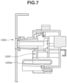
- FIG. 7 is a cross-section diagram illustrating a vicinity of a power button 1200 according to the modification example 1 of the first embodiment.
- a deformable portion 1205 e may have any shape.
- a support portion 1205 is configured to form a hollow circular shape.
- FIG. 8 is a cross-section diagram illustrating a vicinity of a power button 2200 according to the modification example 2 of the first embodiment.
- the power button 2200 is rotatable with a rotational portion 2205 f of a support portion 2205 as a center.
- the power button 2200 is urged due to its own weight in the direction opposite to the first direction, which is the left direction in FIG. 8 , (i.e., a force for tilting in the direction opposite to the first direction is applied to the power button 2200 ).
Landscapes
- Physics & Mathematics (AREA)
- General Physics & Mathematics (AREA)
- Engineering & Computer Science (AREA)
- Microelectronics & Electronic Packaging (AREA)
- Electrophotography Configuration And Component (AREA)
- Accessory Devices And Overall Control Thereof (AREA)
- Push-Button Switches (AREA)
Abstract
Description
Claims (11)
Applications Claiming Priority (2)
| Application Number | Priority Date | Filing Date | Title |
|---|---|---|---|
| JP2022026376A JP7781669B2 (en) | 2022-02-24 | 2022-02-24 | Image forming device |
| JP2022-026376 | 2022-02-24 |
Publications (2)
| Publication Number | Publication Date |
|---|---|
| US20230266697A1 US20230266697A1 (en) | 2023-08-24 |
| US12124207B2 true US12124207B2 (en) | 2024-10-22 |
Family
ID=87574264
Family Applications (1)
| Application Number | Title | Priority Date | Filing Date |
|---|---|---|---|
| US18/164,503 Active US12124207B2 (en) | 2022-02-24 | 2023-02-03 | Image forming apparatus including button portion exposed to outside of casing |
Country Status (2)
| Country | Link |
|---|---|
| US (1) | US12124207B2 (en) |
| JP (1) | JP7781669B2 (en) |
Citations (3)
| Publication number | Priority date | Publication date | Assignee | Title |
|---|---|---|---|---|
| JPH1014158A (en) | 1996-06-25 | 1998-01-16 | Toshiba Corp | Shaft sealing device for rotating electric machines |
| US20100116637A1 (en) * | 2008-11-12 | 2010-05-13 | Hiromi Kano | Button-key structure and electric device having the same |
| US20200065038A1 (en) * | 2018-08-24 | 2020-02-27 | Kyocera Document Solutions Inc. | Operation switch device, image forming apparatus |
Family Cites Families (3)
| Publication number | Priority date | Publication date | Assignee | Title |
|---|---|---|---|---|
| JP3984694B2 (en) * | 1998-01-27 | 2007-10-03 | キヤノン株式会社 | Image forming apparatus |
| JP4508734B2 (en) | 2004-06-15 | 2010-07-21 | 株式会社オートネットワーク技術研究所 | Operation button device |
| JP2006150871A (en) | 2004-11-30 | 2006-06-15 | Seiko Epson Corp | Button switch member and button switch |
-
2022
- 2022-02-24 JP JP2022026376A patent/JP7781669B2/en active Active
-
2023
- 2023-02-03 US US18/164,503 patent/US12124207B2/en active Active
Patent Citations (3)
| Publication number | Priority date | Publication date | Assignee | Title |
|---|---|---|---|---|
| JPH1014158A (en) | 1996-06-25 | 1998-01-16 | Toshiba Corp | Shaft sealing device for rotating electric machines |
| US20100116637A1 (en) * | 2008-11-12 | 2010-05-13 | Hiromi Kano | Button-key structure and electric device having the same |
| US20200065038A1 (en) * | 2018-08-24 | 2020-02-27 | Kyocera Document Solutions Inc. | Operation switch device, image forming apparatus |
Also Published As
| Publication number | Publication date |
|---|---|
| US20230266697A1 (en) | 2023-08-24 |
| JP2023122719A (en) | 2023-09-05 |
| JP7781669B2 (en) | 2025-12-08 |
Similar Documents
| Publication | Publication Date | Title |
|---|---|---|
| US8385800B2 (en) | Fixing device for image forming device, capable of adjusting nip force between heating roller and pressure roller | |
| EP2469349B1 (en) | Process unit and image-forming device using process unit | |
| US8403318B2 (en) | Apparatus for detecting amount of remaining sheets and image forming apparatus including the same | |
| JP6347181B2 (en) | Sheet placing apparatus and image forming apparatus | |
| US10315878B2 (en) | Sheet conveying device, sheet discharging device incorporating the sheet conveying device and image forming apparatus incorporating the sheet conveying device and the sheet discharging device | |
| JP4023468B2 (en) | Image forming apparatus and cartridge | |
| JP4850888B2 (en) | Button key structure and electronic device | |
| US12124207B2 (en) | Image forming apparatus including button portion exposed to outside of casing | |
| JP5240314B2 (en) | Image forming apparatus | |
| US12339485B2 (en) | Display device, operating device and image forming apparatus | |
| EP2372460B1 (en) | Image-forming device | |
| JP5381750B2 (en) | Image forming apparatus | |
| JP5277627B2 (en) | Image forming apparatus | |
| US8807560B2 (en) | Recording sheet guide structure and cartridge | |
| US7817926B2 (en) | Image forming apparatus and optional sheet feeding device | |
| JP5098900B2 (en) | Image forming apparatus | |
| JP2010250206A (en) | Transfer device and image forming apparatus provided with the transfer device | |
| JP2006131348A (en) | Sheet conveying apparatus and image forming apparatus | |
| JP2022037755A (en) | Input device and image forming device | |
| CN116736657A (en) | imaging device | |
| JP2002154695A (en) | Image forming device | |
| JP5093002B2 (en) | Image forming apparatus | |
| JP2023152160A (en) | Image forming device | |
| CN120522989A (en) | Sheet feeding device and image forming device | |
| JP2014026095A (en) | Recording sheet guide structure and cartridge |
Legal Events
| Date | Code | Title | Description |
|---|---|---|---|
| FEPP | Fee payment procedure |
Free format text: ENTITY STATUS SET TO UNDISCOUNTED (ORIGINAL EVENT CODE: BIG.); ENTITY STATUS OF PATENT OWNER: LARGE ENTITY |
|
| AS | Assignment |
Owner name: CANON KABUSHIKI KAISHA, JAPAN Free format text: ASSIGNMENT OF ASSIGNORS INTEREST;ASSIGNOR:YAMAMOTO, DAISUKE;REEL/FRAME:062896/0734 Effective date: 20230124 |
|
| STPP | Information on status: patent application and granting procedure in general |
Free format text: DOCKETED NEW CASE - READY FOR EXAMINATION |
|
| STPP | Information on status: patent application and granting procedure in general |
Free format text: NON FINAL ACTION MAILED |
|
| STPP | Information on status: patent application and granting procedure in general |
Free format text: RESPONSE TO NON-FINAL OFFICE ACTION ENTERED AND FORWARDED TO EXAMINER |
|
| STPP | Information on status: patent application and granting procedure in general |
Free format text: NOTICE OF ALLOWANCE MAILED -- APPLICATION RECEIVED IN OFFICE OF PUBLICATIONS |
|
| STPP | Information on status: patent application and granting procedure in general |
Free format text: PUBLICATIONS -- ISSUE FEE PAYMENT VERIFIED |
|
| STCF | Information on status: patent grant |
Free format text: PATENTED CASE |