US12122462B2 - Vehicle steering system - Google Patents

Vehicle steering system Download PDF

Info

Publication number
US12122462B2
US12122462B2 US17/543,216 US202117543216A US12122462B2 US 12122462 B2 US12122462 B2 US 12122462B2 US 202117543216 A US202117543216 A US 202117543216A US 12122462 B2 US12122462 B2 US 12122462B2
Authority
US
United States
Prior art keywords
pinion shaft
cover member
circumferential surface
pinion
receiving portion
Prior art date
Legal status (The legal status is an assumption and is not a legal conclusion. Google has not performed a legal analysis and makes no representation as to the accuracy of the status listed.)
Active, expires
Application number
US17/543,216
Other versions
US20220177025A1 (en
Inventor
Yoshio Nakada
Current Assignee (The listed assignees may be inaccurate. Google has not performed a legal analysis and makes no representation or warranty as to the accuracy of the list.)
JTEKT Corp
Original Assignee
JTEKT Corp
Priority date (The priority date is an assumption and is not a legal conclusion. Google has not performed a legal analysis and makes no representation as to the accuracy of the date listed.)
Filing date
Publication date
Application filed by JTEKT Corp filed Critical JTEKT Corp
Assigned to JTEKT CORPORATION reassignment JTEKT CORPORATION ASSIGNMENT OF ASSIGNORS INTEREST (SEE DOCUMENT FOR DETAILS). Assignors: NAKADA, YOSHIO
Publication of US20220177025A1 publication Critical patent/US20220177025A1/en
Application granted granted Critical
Publication of US12122462B2 publication Critical patent/US12122462B2/en
Active legal-status Critical Current
Adjusted expiration legal-status Critical

Links

Images

Classifications

    • BPERFORMING OPERATIONS; TRANSPORTING
    • B62LAND VEHICLES FOR TRAVELLING OTHERWISE THAN ON RAILS
    • B62DMOTOR VEHICLES; TRAILERS
    • B62D5/00Power-assisted or power-driven steering
    • B62D5/04Power-assisted or power-driven steering electrical, e.g. using an electric servo-motor connected to, or forming part of, the steering gear
    • B62D5/0403Power-assisted or power-driven steering electrical, e.g. using an electric servo-motor connected to, or forming part of, the steering gear characterised by constructional features, e.g. common housing for motor and gear box
    • BPERFORMING OPERATIONS; TRANSPORTING
    • B62LAND VEHICLES FOR TRAVELLING OTHERWISE THAN ON RAILS
    • B62DMOTOR VEHICLES; TRAILERS
    • B62D1/00Steering controls, i.e. means for initiating a change of direction of the vehicle
    • B62D1/02Steering controls, i.e. means for initiating a change of direction of the vehicle vehicle-mounted
    • B62D1/16Steering columns
    • B62D1/20Connecting steering column to steering gear
    • BPERFORMING OPERATIONS; TRANSPORTING
    • B62LAND VEHICLES FOR TRAVELLING OTHERWISE THAN ON RAILS
    • B62DMOTOR VEHICLES; TRAILERS
    • B62D3/00Steering gears
    • B62D3/02Steering gears mechanical
    • B62D3/12Steering gears mechanical of rack-and-pinion type
    • BPERFORMING OPERATIONS; TRANSPORTING
    • B62LAND VEHICLES FOR TRAVELLING OTHERWISE THAN ON RAILS
    • B62DMOTOR VEHICLES; TRAILERS
    • B62D5/00Power-assisted or power-driven steering
    • B62D5/04Power-assisted or power-driven steering electrical, e.g. using an electric servo-motor connected to, or forming part of, the steering gear
    • B62D5/0421Electric motor acting on or near steering gear
    • FMECHANICAL ENGINEERING; LIGHTING; HEATING; WEAPONS; BLASTING
    • F16ENGINEERING ELEMENTS AND UNITS; GENERAL MEASURES FOR PRODUCING AND MAINTAINING EFFECTIVE FUNCTIONING OF MACHINES OR INSTALLATIONS; THERMAL INSULATION IN GENERAL
    • F16JPISTONS; CYLINDERS; SEALINGS
    • F16J15/00Sealings
    • F16J15/16Sealings between relatively-moving surfaces
    • F16J15/32Sealings between relatively-moving surfaces with elastic sealings, e.g. O-rings
    • F16J15/3204Sealings between relatively-moving surfaces with elastic sealings, e.g. O-rings with at least one lip
    • F16J15/3232Sealings between relatively-moving surfaces with elastic sealings, e.g. O-rings with at least one lip having two or more lips
    • FMECHANICAL ENGINEERING; LIGHTING; HEATING; WEAPONS; BLASTING
    • F16ENGINEERING ELEMENTS AND UNITS; GENERAL MEASURES FOR PRODUCING AND MAINTAINING EFFECTIVE FUNCTIONING OF MACHINES OR INSTALLATIONS; THERMAL INSULATION IN GENERAL
    • F16JPISTONS; CYLINDERS; SEALINGS
    • F16J15/00Sealings
    • F16J15/16Sealings between relatively-moving surfaces
    • F16J15/32Sealings between relatively-moving surfaces with elastic sealings, e.g. O-rings
    • F16J15/324Arrangements for lubrication or cooling of the sealing itself
    • FMECHANICAL ENGINEERING; LIGHTING; HEATING; WEAPONS; BLASTING
    • F16ENGINEERING ELEMENTS AND UNITS; GENERAL MEASURES FOR PRODUCING AND MAINTAINING EFFECTIVE FUNCTIONING OF MACHINES OR INSTALLATIONS; THERMAL INSULATION IN GENERAL
    • F16JPISTONS; CYLINDERS; SEALINGS
    • F16J15/00Sealings
    • F16J15/16Sealings between relatively-moving surfaces
    • F16J15/32Sealings between relatively-moving surfaces with elastic sealings, e.g. O-rings
    • F16J15/3248Sealings between relatively-moving surfaces with elastic sealings, e.g. O-rings provided with casings or supports
    • F16J15/3252Sealings between relatively-moving surfaces with elastic sealings, e.g. O-rings provided with casings or supports with rigid casings or supports
    • BPERFORMING OPERATIONS; TRANSPORTING
    • B62LAND VEHICLES FOR TRAVELLING OTHERWISE THAN ON RAILS
    • B62DMOTOR VEHICLES; TRAILERS
    • B62D6/00Arrangements for automatically controlling steering depending on driving conditions sensed and responded to, e.g. control circuits
    • B62D6/08Arrangements for automatically controlling steering depending on driving conditions sensed and responded to, e.g. control circuits responsive only to driver input torque
    • B62D6/10Arrangements for automatically controlling steering depending on driving conditions sensed and responded to, e.g. control circuits responsive only to driver input torque characterised by means for sensing or determining torque

Definitions

  • the disclosure relates to a vehicle steering system.
  • a vehicle steering system that turns steered wheels (front wheels) of a vehicle according to a steering operation of a steering wheel by a driver includes a rack shaft with rack teeth formed, a pinion shaft with pinion teeth formed, and a housing that receives respective parts of the rack shaft and the pinion shaft, and the rack teeth and the pinion teeth mesh with each other inside the housing.
  • the rack shaft turns the steered wheels via forward or backward movement in a vehicle width direction.
  • the pinion shaft a part of which projects upward from the housing, is connected to the steering wheel via an intermediate shaft and a column shaft swingably connected via respective joints.
  • a cover member in order to curb entry of foreign substances such as water and dirt from an upper end opening of a housing, from which a pinion shaft is led out, a cover member is press-fitted on an outer circumference of a part of the pinion shaft, the part being led out from the housing.
  • the cover member covers the upper end opening of the housing and rotates integrally with the pinion shaft.
  • a sealing ring including a sealing material made of rubber is attached to a part inside the housing, the part being in the vicinity of the upper end opening, and the sealing material is in elastic contact with an outer circumferential surface of the pinion shaft.
  • a torque sensor for detecting a steering torque is disposed below the sealing ring.
  • the steering system Since the steering system is disposed between left and right steered wheels, during, e.g., traveling in rainy weather, the steered wheels sometimes splash the housing and/or the cover member with water.
  • the surface of the pinion shaft gets rusted at the part that is in elastic contact with the sealing material and a part around that part, which may result in decrease in sealing effectiveness of the sealing ring.
  • an object of the disclosure is to provide a vehicle steering system that enables, when a cover member and a housing are splashed with water, curbing entry of the water to the inside of the housing while securing a sufficient gap between the cover member and the housing.
  • the vehicle steering system includes: a rack shaft including a rack teeth portion in which rack teeth are formed; a pinion shaft including a pinion teeth portion in which pinion teeth are formed, the pinion teeth meshing with the rack teeth; a housing including a rack shaft receiving portion that receives a part of the rack shaft and a pinion shaft receiving portion that receives a part of the pinion shaft; and a cover member disposed above the pinion shaft receiving portion.
  • the part of the pinion shaft projects upward from an upper end opening of the pinion shaft receiving portion.
  • the cover member includes a disc-like hood portion that covers the upper end opening and an annular side wall portion that faces an outer circumferential surface of the pinion shaft receiving portion across a gap.
  • the pinion shaft is inserted through the hood portion.
  • the side wall portion includes a valve portion capable of coming into abutment with the outer circumferential surface of the pinion shaft receiving portion by being elastically deformed by pressure received from water splashing when a vehicle is traveling.
  • the above configuration enables, when a cover member and a housing are splashed with water, curbing entry of the water to the inside of the housing while securing a sufficient gap between the cover member and the housing.
  • FIG. 3 is a sectional view along line in FIG. 2 ;
  • FIG. 4 A is a side view of a cover member
  • FIG. 4 B is a sectional view of the cover member
  • FIG. 4 C is a sectional perspective view of the cover member.
  • FIG. 5 A is a sectional view illustrating a part around a side wall portion of the cover member in normal times
  • FIG. 5 B is a sectional view illustrating the part around the side wall portion of the cover member when splashed with water
  • FIG. 6 A is a sectional view illustrating a cover member according to a second embodiment in a normal state
  • FIG. 6 B is a sectional view illustrating a part around the cover member when splashed with water
  • FIG. 7 A is a sectional view illustrating a cover member according to a third embodiment in a normal state.
  • FIG. 7 B is a sectional view illustrating a part around the cover member when splashed with water.
  • FIG. 1 is an overall configuration diagram schematically illustrating a rack-and-pinion steering system according to a first embodiment of the disclosure.
  • FIG. 2 is an outer appearance diagram illustrating a part of the steering system partially cut away.
  • FIG. 3 is a sectional view along line in FIG. 2 .
  • a steering system 1 is mounted in a vehicle and turns front wheels 14 L, 14 R, which are steered wheels, according to a steering operation by a driver.
  • FIGS. 1 and 2 illustrate the steering system as viewed from the vehicle front side, and the left side of each of the figures is the right side of the vehicle and the right side of each of the figures is the left side of the vehicle.
  • the letter “R” in a reference sign in FIG. 1 denotes the right side of the vehicle and the letter “L” in a reference sign in FIG. 1 denotes the left side of the vehicle.
  • “upper (up)”, “lower (down)”, “left”, and “right” refer to respective directions in a vehicle height direction and a vehicle left-right direction in a state in which the steering system 1 is mounted in a vehicle.
  • the steering system 1 includes a steering shaft 2 that rotates according to a steering operation of a steering wheel 11 by the driver, a rack shaft 3 extending in the vehicle left-right direction, a housing 4 (see FIG. 2 ) fixed to a vehicle body, a torque sensor 5 that detects a steering torque, a steering assist device 6 that generates a steering assist force according to the steering torque detected by the torque sensor 5 , and a cover member 7 for curbing entry of foreign substances to the inside of the housing 4 .
  • the steering shaft 2 includes a column shaft 21 including one end portion to which the steering wheel 11 is fixed, an intermediate shaft 23 connected to the other end portion of the column shaft 21 via a universal joint 22 , and a pinion shaft 25 connected to the intermediate shaft 23 via a universal joint 24 .
  • the pinion shaft 25 includes an intermediate shaft 23 -side upper member 251 , a torsion bar 252 to be twisted by a steering torque, and a lower member 253 connected to the upper member 251 via the torsion bar 252 . Also, the pinion shaft 25 includes a pinion teeth portion 254 in which pinion teeth 254 a are formed. The pinion teeth portion 254 is provided at a lower end portion of the lower member 253 .
  • the upper member 251 and the lower member 253 are formed of a high stiffness metal such as carbon steel, and the torsion bar 252 is formed of a metal such as spring steel having elasticity such that the steel is twisted by a steering torque.
  • the pinion shaft 25 rotates around a rotation axis O (see FIG. 3 ) along with rotation of the steering wheel 11 .
  • the rack shaft 3 includes a first rack teeth portion 31 in which first rack teeth 31 a are formed and a second rack teeth portion 32 in which second rack teeth 32 a are formed.
  • the pinion teeth 254 a of the pinion shaft 25 mesh with the first rack teeth 31 a .
  • Left and right tie rods 13 L, 13 R are connected to opposite end portions of the rack shaft 3 via ball joints 12 L, 12 R, respectively.
  • the left and right tie rods 13 L, 13 R are connected to knuckles that support the left and right front wheels 14 L, 14 R, respectively.
  • the left and right tie rods 13 L, 13 R each swing relative to the rack shaft 3 and the left and right front wheels 14 L, 14 R are turned, respectively.
  • the housing 4 includes a rack shaft receiving portion 41 that receives a part of the rack shaft 3 , a pinion shaft receiving portion 42 that receives a part of the pinion shaft 25 , and an output shaft receiving portion 43 that receives the output shaft 64 of the steering assist device 6 , in an integrated manner.
  • the opposite end portions of the rack shaft 3 project from the rack shaft receiving portion 41 in the left-right direction, and an upper end portion of the pinion shaft 25 projects upward from the pinion shaft receiving portion 42 .
  • the pinion shaft receiving portion 42 includes a base portion 421 made of a metal such as an aluminum alloy, the base portion 421 being molded integrally with the rack shaft receiving portion 41 , and a holder portion 422 made of a resin, the holder portion 422 being attached to the upper side of the base portion 421 .
  • the first rack teeth portion 31 of the rack shaft 3 is elastically pushed against the pinion teeth portion 254 of the pinion shaft 25 by a rack guide mechanism 44 provided in the base portion 421 .
  • the holder portion 422 is formed of, for example, a resin, such as polypropylene, having stiffness enhanced by addition of glass fiber, and is formed in a cylindrical shape with the rotation axis O as a center.
  • the holder portion 422 holds the torque sensor 5 , first and second bearings 81 , 82 , and a sealing ring 9 inside.
  • Each of the first and second bearings 81 , 82 is a ball bearing with a plurality of balls disposed as rolling elements between an inner ring and an outer ring.
  • the first bearing 81 supports the upper member 251 on the upper side of the torque sensor 5 and the second bearing 82 supports the lower member 253 on the lower side of the torque sensor 5 .
  • a shaft hole 251 a is formed in a center portion of the upper member 251 , and an upper end portion of the torsion bar 252 is received inside the shaft hole 251 a .
  • the torsion bar 252 is fixed to the upper member 251 by a fixing pin 255 in such a manner as to be non-rotatable relative to the upper member 251 .
  • a lower end portion of the torsion bar 252 is fixed to the lower member 253 in such a manner as to be non-rotatable relative to the lower member 253 , via spline-fitting of the lower end portion in a fitting hole 253 a formed in the lower member 253 .
  • the torque sensor 5 includes a ring magnet 51 fixed to the upper member 251 , a magnetism collection ring assembly 52 fixed to the holder portion 422 , a magnetic yoke assembly 54 fixed to the lower member 253 by an annular collar 53 , and a magnetic field detection element 55 .
  • the ring magnet 51 and the magnetic yoke assembly 54 turn relative to each other and an intensity of a magnetic field passing through the magnetism collection ring assembly 52 varies. Then, the steering torque is detected by the magnetic field intensity variation being captured by the magnetic field detection element 55 .
  • the sealing ring 9 includes a core metal 91 and a sealing rubber 92 and is fixedly fitted to the inner side of the holder portion 422 on the upper side relative to the first bearing 81 .
  • the sealing rubber 92 includes first and second sealing lips 921 , 922 that come into sliding contact with an outer circumferential surface 251 b of the upper member 251 of the pinion shaft 25 , curbing entry of foreign substances (including liquids and solids) from an upper end opening 420 of the pinion shaft receiving portion 42 to the inside of the pinion shaft receiving portion 42 .
  • the upper end opening 420 is an end portion on the vertically upper side of the holder portion 422 .
  • a part of the upper member 251 of the pinion shaft 25 projects upward from the upper end opening 420 of the pinion shaft receiving portion 42 .
  • the cover member 7 is disposed above the pinion shaft receiving portion 42 , and grease G is injected between the sealing ring 9 and the cover member 7 .
  • the grease G covers an entire circumference of a part, between the sealing ring 9 and the cover member 7 , of the outer circumferential surface 251 b of the upper member 251 .
  • a through-hole 70 is formed in a center portion of the hood portion 71 and the upper member 251 of the pinion shaft 25 is inserted through the through-hole 70 .
  • a plurality of ribs 711 for strength and stiffness enhancement are provided at the hood portion 71 .
  • the weir portion 73 curbs an escape of the grease G.
  • an annular groove 251 c that extends circumferentially is formed.
  • the cover member 7 is axially positioned relative to and fixed to the pinion shaft 25 by the hood portion 71 being fitted in the groove 251 c , and rotates together with the pinion shaft 25 .
  • the cover member 7 and a part around the cover member 7 are splashed with water by the front wheel 14 R.
  • FIG. 5 A is an enlarged sectional view of a part around the side wall portion 72 of the cover member 7 in normal times and FIG. 5 B is a sectional view illustrating that part when splashed with water.
  • the side wall portion 72 includes a cylindrical base portion 721 that extends downward from an outer edge of the hood portion 71 , and a valve portion 722 provided under the base portion 721 .
  • the valve portion 722 has a cylindrical shape that is thinner than the base portion 721 , and is capable of coming into abutment with the outer circumferential surface 42 a of the pinion shaft receiving portion 42 by being elastically deformed by pressure received from water splashing when the vehicle is traveling.
  • FIG. 5 A is an enlarged sectional view of a part around the side wall portion 72 of the cover member 7 in normal times
  • FIG. 5 B is a sectional view illustrating that part when splashed with water.
  • the side wall portion 72 includes a cylindrical base portion 721 that extends downward from an outer edge of the hood portion 71
  • FIG. 5 B illustrates a state in which a lower end portion of the valve portion 722 is in abutment with the outer circumferential surface 42 a of the pinion shaft receiving portion 42 . Also, in FIG. 5 B , as an example, a direction in which water splashes via the front wheel 14 R is indicated by a plurality of arrows.
  • an outer circumferential surface 722 a and an inner circumferential surface 722 b of the valve portion 722 are parallel to the rotation axis O.
  • the outer circumferential surface 722 a of the valve portion 722 is continuous with the outer tapered surface 721 a of the base portion 721 and the inner circumferential surface 722 b of the valve portion 722 is continuous with the inner tapered surface 721 b of the base portion 721 .
  • the valve portion 722 of the cover member 7 is elastically deformed by pressure received from water splashing when the vehicle is traveling, curbing entry of the water to the inside of the cover member 7 . Also, where the pressure of the water is high, the valve portion 722 comes into abutment with the outer circumferential surface 42 a of the pinion shaft receiving portion 42 and entry of the water from the part of the abutment is thus prevented, enabling curbing entry of the water to the inside of the cover member 7 even where the pressure of the water is high.
  • the base portion 721 includes the outer tapered surface 721 a , and thus, the base portion 721 easily receives pressure of water via the outer tapered surface 721 a and thus easily elastically deforms inward. Then, in the part in which the base portion 721 has elastically deformed, the valve portion 722 becomes closer to the outer circumferential surface 42 a of the pinion shaft receiving portion 42 , and thus, the valve portion 722 more easily comes into abutment with the outer circumferential surface 42 a of the pinion shaft receiving portion 42 .
  • the base portion 721 includes the inner tapered surface 721 b , which makes the base portion 721 more decrease in thickness and stiffness as farther in the lower end portion in combination with the outer tapered surface 721 a , and thus, in particular, the base portion 721 more easily elastically deforms as farther in the lower end portion. Therefore, the valve portion 722 even more easily comes into abutment with the outer circumferential surface 42 a of the pinion shaft receiving portion 42 .
  • cover member 7 includes no valve portion 722 , in an early state of use in which there is a sufficient amount of a gel lubricant such as the grease G covering the part, between the sealing ring 9 and the hood portion 71 of the cover member 7 , of the outer circumferential surface 251 b of the pinion shaft 25 (state illustrated in FIG.
  • the sealing lips 921 , 922 of the sealing ring 9 being in contact with the area, along with rotation of the pinion shaft 25 , the sealing lips 921 , 922 are worn by the rust, which may result in decrease in sealing effectiveness of the sealing ring 9 .
  • entry of water to the inside of the cover member 7 can be curbed by the valve portion 722 , enabling securing the amount of the grease G for a long period of time and thus enabling prevention of rusting.
  • the sealing lips 921 , 922 can be prevented from becoming worn, enabling maintaining the sealing effectiveness of the sealing ring 9 for a long period of time.
  • FIGS. 6 A and 6 B a shape of a cover member 7 A is different from the shape of the cover member 7 according to the first embodiment. Since the rest of the configuration is similar to that of the first embodiment, in FIGS. 6 A and 6 B , components that are in common with the first embodiment are provided with reference signs that are the same as those provided in FIG. 3 , etc., and overlapping descriptions thereof will be omitted.
  • FIG. 6 A is a sectional view illustrating a part around a cover member 7 A in normal times and FIG. 6 B is a sectional view illustrating a part around the cover member 7 A when splashed with water.
  • the cover member 7 A according to the present embodiment includes a hood portion 71 and a side wall portion 72 , and the side wall portion 72 includes a base portion 721 and a valve portion 722 ; however, in normal times in which no water splashes, an inner circumferential surface 721 c of the base portion 721 is parallel to a rotation axis O of a pinion shaft 25 .
  • An inner diameter of the base portion 721 is smaller than an inner diameter of the valve portion 722 , and a step portion 723 is formed entirely circumferentially between the inner circumferential surface 721 c of the base portion 721 and an inner circumferential surface 722 b of the valve portion 722 .
  • the cover member 7 A according to the second embodiment also enables entry of water splashing when a vehicle is traveling to the inside of the cover member 7 A to be curbed by the valve portion 722 being elastically deformed by pressure received from the water.
  • FIGS. 7 A and 7 B a shape of a cover member 7 B is different from the shape of the cover member 7 according to the first embodiment. Since the rest of the configuration is similar to that of the first embodiment, in FIGS. 7 A and 7 B , components that are in common with the first embodiment are provided with reference signs that are the same as those provided in FIG. 3 , etc., and overlapping descriptions thereof will be omitted.
  • FIG. 7 A is a sectional view illustrating a part around a cover member 7 B in normal times and FIG. 7 B is a sectional view illustrating a part around the cover member 7 B when splashed with water.
  • the cover member 7 B according to the present embodiment includes a hood portion 71 and a side wall portion 72 and the side wall portion 72 includes a base portion 721 and a valve portion 722 ; however, the valve portion 722 is annularly provided on the inner side of the base portion 721 and faces a small-diameter portion 42 b in an outer circumferential surface 42 a of a pinion shaft receiving portion 42 .
  • the valve portion 722 projects radially inward from an inner circumferential surface 721 d of the base portion 721 and projects toward the lower side in FIG. 7 A and has a tapered shape that decrease in inner and outer diameters toward the lower end portion side.
  • the valve portion 722 is not in abutment with the outer circumferential surface 42 a of the pinion shaft receiving portion 42 in normal times, and upon being splashed with water when a vehicle is traveling, the valve portion 722 is elastically deformed by pressure of the water, and as illustrated in FIG. 7 B , the lower end portion comes into abutment with the outer circumferential surface 42 a of the pinion shaft receiving portion 42 . Consequently, entry of the water to the upper side relative to the valve portion 722 can be curbed.
  • the cover member 7 B according to the third embodiment also enables entry of water splashing when the vehicle is traveling to the inside of the cover member 7 B to be curbed by the valve portion 722 being elastically deformed by pressure received from the water.
  • the holder portion 422 of the pinion shaft receiving portion 42 is made of a resin
  • the holder portion 422 may be made of a metal such as an aluminum alloy like the base portion 421 .
  • the above first to third embodiments have been described in terms of the case where the torque sensor 5 is disposed below the sealing ring 9 in the pinion shaft receiving portion 42 , no torque sensor 5 may be disposed in the pinion shaft receiving portion 42 .
  • a valve portion 722 may further be provided on the inner side of the base portion 721 .
  • a plurality of valve portions 722 of the third embodiment may be provided in such a manner as to be aligned along the height direction on the inner side of the base portion 721 .
  • first to third embodiments each indicate the steering system 1 in which the components from the steering wheel 11 to the pinion shaft 25 are mechanically connected
  • the disclosure may be applied also to a steer-by-wire apparatus in which components from a steering wheel to a pinion shaft are connected via a clutch capable of being engaged and disengaged or a steer-by-wire apparatus including no mechanism that connects components from a steering wheel to a pinion shaft.

Landscapes

  • Engineering & Computer Science (AREA)
  • Mechanical Engineering (AREA)
  • Chemical & Material Sciences (AREA)
  • Combustion & Propulsion (AREA)
  • Transportation (AREA)
  • General Engineering & Computer Science (AREA)
  • Power Steering Mechanism (AREA)
  • Sealing With Elastic Sealing Lips (AREA)
  • Sealing Devices (AREA)
  • Transmission Devices (AREA)

Abstract

A vehicle steering system includes a rack shaft, a pinion shaft, a housing including a rack shaft receiving portion and a pinion shaft receiving portion, and a cover member disposed above the pinion shaft receiving portion. A part of the pinion shaft projects upward from an upper end opening of the pinion shaft receiving portion. The cover member includes a hood portion and an annular side wall portion. The pinion shaft is inserted through the hood portion. The side wall portion includes a valve portion capable of coming into abutment with an outer circumferential surface of the pinion shaft receiving portion.

Description

CROSS-REFERENCE TO RELATED APPLICATION
This application claims priority to Japanese Patent Application No. 2020-204008 filed on Dec. 9, 2020, incorporated herein by reference in its entirety.
BACKGROUND 1. Technical Field
The disclosure relates to a vehicle steering system.
2. Description of Related Art
A vehicle steering system that turns steered wheels (front wheels) of a vehicle according to a steering operation of a steering wheel by a driver includes a rack shaft with rack teeth formed, a pinion shaft with pinion teeth formed, and a housing that receives respective parts of the rack shaft and the pinion shaft, and the rack teeth and the pinion teeth mesh with each other inside the housing. The rack shaft turns the steered wheels via forward or backward movement in a vehicle width direction. The pinion shaft, a part of which projects upward from the housing, is connected to the steering wheel via an intermediate shaft and a column shaft swingably connected via respective joints.
In a steering system described in Japanese Unexamined Patent Application Publication No. 2019-107926, in order to curb entry of foreign substances such as water and dirt from an upper end opening of a housing, from which a pinion shaft is led out, a cover member is press-fitted on an outer circumference of a part of the pinion shaft, the part being led out from the housing. The cover member covers the upper end opening of the housing and rotates integrally with the pinion shaft. Also, a sealing ring including a sealing material made of rubber is attached to a part inside the housing, the part being in the vicinity of the upper end opening, and the sealing material is in elastic contact with an outer circumferential surface of the pinion shaft. A torque sensor for detecting a steering torque is disposed below the sealing ring.
SUMMARY
Since the steering system is disposed between left and right steered wheels, during, e.g., traveling in rainy weather, the steered wheels sometimes splash the housing and/or the cover member with water. In the steering system configured as above, if water enters from a gap between the cover member and the housing and is accumulated, the surface of the pinion shaft gets rusted at the part that is in elastic contact with the sealing material and a part around that part, which may result in decrease in sealing effectiveness of the sealing ring.
In order to prevent such entry of water, it is conceivable to design the gap between the cover member and the housing to be small; however, in this case, the cover member and the housing may come into constant contact with each other because of a slight dimension error of the cover member or the housing, which may cause, e.g., an increase in rotational resistance generated when the cover member rotates together with the pinion shaft or cause noise to be generated when the cover member rubs on a surface of the housing, and give a feeling of discomfort to, e.g., a driver who hears the noise.
Therefore, an object of the disclosure is to provide a vehicle steering system that enables, when a cover member and a housing are splashed with water, curbing entry of the water to the inside of the housing while securing a sufficient gap between the cover member and the housing.
An aspect of the disclosure provides a vehicle steering system. The vehicle steering system includes: a rack shaft including a rack teeth portion in which rack teeth are formed; a pinion shaft including a pinion teeth portion in which pinion teeth are formed, the pinion teeth meshing with the rack teeth; a housing including a rack shaft receiving portion that receives a part of the rack shaft and a pinion shaft receiving portion that receives a part of the pinion shaft; and a cover member disposed above the pinion shaft receiving portion. The part of the pinion shaft projects upward from an upper end opening of the pinion shaft receiving portion. The cover member includes a disc-like hood portion that covers the upper end opening and an annular side wall portion that faces an outer circumferential surface of the pinion shaft receiving portion across a gap. The pinion shaft is inserted through the hood portion. The side wall portion includes a valve portion capable of coming into abutment with the outer circumferential surface of the pinion shaft receiving portion by being elastically deformed by pressure received from water splashing when a vehicle is traveling.
The above configuration enables, when a cover member and a housing are splashed with water, curbing entry of the water to the inside of the housing while securing a sufficient gap between the cover member and the housing.
BRIEF DESCRIPTION OF THE DRAWINGS
Features, advantages, and technical and industrial significance of exemplary embodiments of the disclosure will be described below with reference to the accompanying drawings, in which like signs denote like elements, and wherein:
FIG. 1 is an overall configuration diagram schematically illustrating a rack-and-pinion steering system according to a first embodiment of the disclosure;
FIG. 2 is an outer appearance diagram illustrating a part of a steering system partially cut away;
FIG. 3 is a sectional view along line in FIG. 2 ;
FIG. 4A is a side view of a cover member;
FIG. 4B is a sectional view of the cover member;
FIG. 4C is a sectional perspective view of the cover member.
FIG. 5A is a sectional view illustrating a part around a side wall portion of the cover member in normal times;
FIG. 5B is a sectional view illustrating the part around the side wall portion of the cover member when splashed with water;
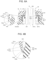
FIG. 6A is a sectional view illustrating a cover member according to a second embodiment in a normal state;
FIG. 6B is a sectional view illustrating a part around the cover member when splashed with water;
FIG. 7A is a sectional view illustrating a cover member according to a third embodiment in a normal state; and
FIG. 7B is a sectional view illustrating a part around the cover member when splashed with water.
DETAILED DESCRIPTION OF EMBODIMENTS First Embodiment
A first embodiment of the disclosure will be described with reference to the drawings. Note that the below-described embodiments each indicate a preferable specific example in carrying out the disclosure and specifically indicate, by example, various technical matters that are technically preferable; however, the technical scope of the disclosure is not limited to these specific modes.
Overall Configuration of Steering System
FIG. 1 is an overall configuration diagram schematically illustrating a rack-and-pinion steering system according to a first embodiment of the disclosure. FIG. 2 is an outer appearance diagram illustrating a part of the steering system partially cut away. FIG. 3 is a sectional view along line in FIG. 2 . A steering system 1 is mounted in a vehicle and turns front wheels 14L, 14R, which are steered wheels, according to a steering operation by a driver.
FIGS. 1 and 2 illustrate the steering system as viewed from the vehicle front side, and the left side of each of the figures is the right side of the vehicle and the right side of each of the figures is the left side of the vehicle. The letter “R” in a reference sign in FIG. 1 denotes the right side of the vehicle and the letter “L” in a reference sign in FIG. 1 denotes the left side of the vehicle. In the below description, “upper (up)”, “lower (down)”, “left”, and “right” refer to respective directions in a vehicle height direction and a vehicle left-right direction in a state in which the steering system 1 is mounted in a vehicle.
The steering system 1 includes a steering shaft 2 that rotates according to a steering operation of a steering wheel 11 by the driver, a rack shaft 3 extending in the vehicle left-right direction, a housing 4 (see FIG. 2 ) fixed to a vehicle body, a torque sensor 5 that detects a steering torque, a steering assist device 6 that generates a steering assist force according to the steering torque detected by the torque sensor 5, and a cover member 7 for curbing entry of foreign substances to the inside of the housing 4. The steering shaft 2 includes a column shaft 21 including one end portion to which the steering wheel 11 is fixed, an intermediate shaft 23 connected to the other end portion of the column shaft 21 via a universal joint 22, and a pinion shaft 25 connected to the intermediate shaft 23 via a universal joint 24.
The pinion shaft 25 includes an intermediate shaft 23-side upper member 251, a torsion bar 252 to be twisted by a steering torque, and a lower member 253 connected to the upper member 251 via the torsion bar 252. Also, the pinion shaft 25 includes a pinion teeth portion 254 in which pinion teeth 254 a are formed. The pinion teeth portion 254 is provided at a lower end portion of the lower member 253. The upper member 251 and the lower member 253 are formed of a high stiffness metal such as carbon steel, and the torsion bar 252 is formed of a metal such as spring steel having elasticity such that the steel is twisted by a steering torque. The pinion shaft 25 rotates around a rotation axis O (see FIG. 3 ) along with rotation of the steering wheel 11.
The rack shaft 3 includes a first rack teeth portion 31 in which first rack teeth 31 a are formed and a second rack teeth portion 32 in which second rack teeth 32 a are formed. The pinion teeth 254 a of the pinion shaft 25 mesh with the first rack teeth 31 a. Left and right tie rods 13L, 13R are connected to opposite end portions of the rack shaft 3 via ball joints 12L, 12R, respectively. The left and right tie rods 13L, 13R are connected to knuckles that support the left and right front wheels 14L, 14R, respectively. Upon the rack shaft 3 making a forward or backward movement in a vehicle width direction (left-right direction), the left and right tie rods 13L, 13R each swing relative to the rack shaft 3 and the left and right front wheels 14L, 14R are turned, respectively.
The steering assist device 6 includes a control device 61 capable of acquiring a detection signal from the torque sensor 5, an electric motor 62 that generates a steering assist force via a motor current output from the control device 61, a speed reduction mechanism 63 that reduces a speed of rotation of an output shaft 621 of the electric motor 62, and an output shaft 64 to be rotated by a torque of the electric motor 62, the torque being reduced by the speed reduction mechanism 63. The speed reduction mechanism 63 includes a worm gear 631 connected to the output shaft 621 of the electric motor 62 in such a manner as to rotate integrally with the output shaft 621, and a worm wheel 632 that meshes with the worm gear 631. The output shaft 64 includes a pinion teeth portion 641 in which pinion teeth 641 a are formed, the pinion teeth 641 a meshing with the second rack teeth 32 a.
The housing 4 includes a rack shaft receiving portion 41 that receives a part of the rack shaft 3, a pinion shaft receiving portion 42 that receives a part of the pinion shaft 25, and an output shaft receiving portion 43 that receives the output shaft 64 of the steering assist device 6, in an integrated manner. The opposite end portions of the rack shaft 3 project from the rack shaft receiving portion 41 in the left-right direction, and an upper end portion of the pinion shaft 25 projects upward from the pinion shaft receiving portion 42.
As illustrated in FIG. 3 , the pinion shaft receiving portion 42 includes a base portion 421 made of a metal such as an aluminum alloy, the base portion 421 being molded integrally with the rack shaft receiving portion 41, and a holder portion 422 made of a resin, the holder portion 422 being attached to the upper side of the base portion 421. The first rack teeth portion 31 of the rack shaft 3 is elastically pushed against the pinion teeth portion 254 of the pinion shaft 25 by a rack guide mechanism 44 provided in the base portion 421.
The holder portion 422 is formed of, for example, a resin, such as polypropylene, having stiffness enhanced by addition of glass fiber, and is formed in a cylindrical shape with the rotation axis O as a center. The holder portion 422 holds the torque sensor 5, first and second bearings 81, 82, and a sealing ring 9 inside. Each of the first and second bearings 81, 82 is a ball bearing with a plurality of balls disposed as rolling elements between an inner ring and an outer ring. The first bearing 81 supports the upper member 251 on the upper side of the torque sensor 5 and the second bearing 82 supports the lower member 253 on the lower side of the torque sensor 5.
A shaft hole 251 a is formed in a center portion of the upper member 251, and an upper end portion of the torsion bar 252 is received inside the shaft hole 251 a. The torsion bar 252 is fixed to the upper member 251 by a fixing pin 255 in such a manner as to be non-rotatable relative to the upper member 251. A lower end portion of the torsion bar 252 is fixed to the lower member 253 in such a manner as to be non-rotatable relative to the lower member 253, via spline-fitting of the lower end portion in a fitting hole 253 a formed in the lower member 253.
The torque sensor 5 includes a ring magnet 51 fixed to the upper member 251, a magnetism collection ring assembly 52 fixed to the holder portion 422, a magnetic yoke assembly 54 fixed to the lower member 253 by an annular collar 53, and a magnetic field detection element 55. Upon the torsion bar 252 being twisted by a steering torque, the ring magnet 51 and the magnetic yoke assembly 54 turn relative to each other and an intensity of a magnetic field passing through the magnetism collection ring assembly 52 varies. Then, the steering torque is detected by the magnetic field intensity variation being captured by the magnetic field detection element 55.
The sealing ring 9 includes a core metal 91 and a sealing rubber 92 and is fixedly fitted to the inner side of the holder portion 422 on the upper side relative to the first bearing 81. The sealing rubber 92 includes first and second sealing lips 921, 922 that come into sliding contact with an outer circumferential surface 251 b of the upper member 251 of the pinion shaft 25, curbing entry of foreign substances (including liquids and solids) from an upper end opening 420 of the pinion shaft receiving portion 42 to the inside of the pinion shaft receiving portion 42. The upper end opening 420 is an end portion on the vertically upper side of the holder portion 422.
A part of the upper member 251 of the pinion shaft 25 projects upward from the upper end opening 420 of the pinion shaft receiving portion 42. The cover member 7 is disposed above the pinion shaft receiving portion 42, and grease G is injected between the sealing ring 9 and the cover member 7. The grease G covers an entire circumference of a part, between the sealing ring 9 and the cover member 7, of the outer circumferential surface 251 b of the upper member 251.
FIG. 4A is a side view of the cover member 7 and FIG. 4B is a sectional view of the cover member 7. FIG. 4C is a sectional perspective view of the cover member 7. The cover member 7 is formed of, for example, rubber such as acrylonitrile-butadiene rubber (NBR), and includes a disc-like hood portion 71 that covers the upper end opening 420 of the pinion shaft receiving portion 42, an annular side wall portion 72 that faces a part, in the vicinity of the upper end opening 420, of the outer circumferential surface 42 a (illustrated in FIG. 3 ) of the pinion shaft receiving portion 42 across a gap, and an annular weir portion 73 provided on the lower side of the hood portion 71, in an integrated manner. A through-hole 70 is formed in a center portion of the hood portion 71 and the upper member 251 of the pinion shaft 25 is inserted through the through-hole 70. A plurality of ribs 711 for strength and stiffness enhancement are provided at the hood portion 71. The weir portion 73 curbs an escape of the grease G.
In a part of the outer circumferential surface 251 b of the upper member 251, the part projecting upward from the upper end opening 420 of the pinion shaft receiving portion 42, an annular groove 251 c that extends circumferentially is formed. The cover member 7 is axially positioned relative to and fixed to the pinion shaft 25 by the hood portion 71 being fitted in the groove 251 c, and rotates together with the pinion shaft 25. For example, when the front wheel 14R runs through a puddle P (illustrated in FIG. 1 ), the cover member 7 and a part around the cover member 7 are splashed with water by the front wheel 14R.
FIG. 5A is an enlarged sectional view of a part around the side wall portion 72 of the cover member 7 in normal times and FIG. 5B is a sectional view illustrating that part when splashed with water. The side wall portion 72 includes a cylindrical base portion 721 that extends downward from an outer edge of the hood portion 71, and a valve portion 722 provided under the base portion 721. The valve portion 722 has a cylindrical shape that is thinner than the base portion 721, and is capable of coming into abutment with the outer circumferential surface 42 a of the pinion shaft receiving portion 42 by being elastically deformed by pressure received from water splashing when the vehicle is traveling. FIG. 5B illustrates a state in which a lower end portion of the valve portion 722 is in abutment with the outer circumferential surface 42 a of the pinion shaft receiving portion 42. Also, in FIG. 5B, as an example, a direction in which water splashes via the front wheel 14R is indicated by a plurality of arrows.
The base portion 721 is higher in stiffness than the valve portion 722 and includes a lower end portion that decreases in thickness toward the valve portion 722 side. At least a part of an outer circumferential surface of the base portion 721 is an outer tapered surface 721 a that decreases in outer diameter toward the lower side, and at least a part of an inner circumferential surface of the base portion 721 is an inner tapered surface 721 b that increases in inner diameter toward the lower side. In other words, the base portion 721 more decreases in stiffness as farther in the lower end portion, and thus, is easily deformed radially inward by pressure received from water splashing on the outer tapered surface 721 a.
In normal times in which no water splashes, an outer circumferential surface 722 a and an inner circumferential surface 722 b of the valve portion 722 are parallel to the rotation axis O. The outer circumferential surface 722 a of the valve portion 722 is continuous with the outer tapered surface 721 a of the base portion 721 and the inner circumferential surface 722 b of the valve portion 722 is continuous with the inner tapered surface 721 b of the base portion 721. A part, inside the side wall portion 72, of the outer circumferential surface 42 a of the pinion shaft receiving portion 42 has a stepped shape in which an outer diameter of a small-diameter portion 42 b facing the inner tapered surface 721 b of the base portion 721 is smaller than an outer diameter of a large-diameter portion 42 c facing the inner circumferential surface 722 b of the valve portion 722 and a step portion 42 d is formed between the small-diameter portion 42 b and the large-diameter portion 42 c.
In the steering system 1 configured as above, the valve portion 722 of the cover member 7 is elastically deformed by pressure received from water splashing when the vehicle is traveling, curbing entry of the water to the inside of the cover member 7. Also, where the pressure of the water is high, the valve portion 722 comes into abutment with the outer circumferential surface 42 a of the pinion shaft receiving portion 42 and entry of the water from the part of the abutment is thus prevented, enabling curbing entry of the water to the inside of the cover member 7 even where the pressure of the water is high.
Also, in the present embodiment, the base portion 721 includes the outer tapered surface 721 a, and thus, the base portion 721 easily receives pressure of water via the outer tapered surface 721 a and thus easily elastically deforms inward. Then, in the part in which the base portion 721 has elastically deformed, the valve portion 722 becomes closer to the outer circumferential surface 42 a of the pinion shaft receiving portion 42, and thus, the valve portion 722 more easily comes into abutment with the outer circumferential surface 42 a of the pinion shaft receiving portion 42.
Furthermore, in the present embodiment, the base portion 721 includes the inner tapered surface 721 b, which makes the base portion 721 more decrease in thickness and stiffness as farther in the lower end portion in combination with the outer tapered surface 721 a, and thus, in particular, the base portion 721 more easily elastically deforms as farther in the lower end portion. Therefore, the valve portion 722 even more easily comes into abutment with the outer circumferential surface 42 a of the pinion shaft receiving portion 42.
Even where the cover member 7 includes no valve portion 722, in an early state of use in which there is a sufficient amount of a gel lubricant such as the grease G covering the part, between the sealing ring 9 and the hood portion 71 of the cover member 7, of the outer circumferential surface 251 b of the pinion shaft 25 (state illustrated in FIG. 3 ), even if water enters the inside of the cover member 7, rusting of the outer circumferential surface 251 b of the upper member 251 can be prevented by a waterproof effect and an antirust effect of the grease G; however, if water repeatedly enters the inside of the cover member 7 and a flow rate and a flow volume of the entered water are large, the grease G is swept away by the water and the outer circumferential surface 251 b of the upper member 251 easily gets rusted. If the outer circumferential surface 251 b of the upper member 251 is rusted, sealing effectiveness of the sealing ring 9 may decrease. In particular, if the rust spreads from the area of the outer circumferential surface 251 b, the area being previously covered by the grease G, to an area of the outer circumferential surface 251 b, the sealing lips 921, 922 of the sealing ring 9 being in contact with the area, along with rotation of the pinion shaft 25, the sealing lips 921, 922 are worn by the rust, which may result in decrease in sealing effectiveness of the sealing ring 9. In the present embodiment, entry of water to the inside of the cover member 7 can be curbed by the valve portion 722, enabling securing the amount of the grease G for a long period of time and thus enabling prevention of rusting. As a result, the sealing lips 921, 922 can be prevented from becoming worn, enabling maintaining the sealing effectiveness of the sealing ring 9 for a long period of time.
Second Embodiment
Next, a second embodiment of the disclosure will be described with reference to FIGS. 6A and 6B. In the second embodiment, a shape of a cover member 7A is different from the shape of the cover member 7 according to the first embodiment. Since the rest of the configuration is similar to that of the first embodiment, in FIGS. 6A and 6B, components that are in common with the first embodiment are provided with reference signs that are the same as those provided in FIG. 3 , etc., and overlapping descriptions thereof will be omitted.
FIG. 6A is a sectional view illustrating a part around a cover member 7A in normal times and FIG. 6B is a sectional view illustrating a part around the cover member 7A when splashed with water. As with the cover member 7 according to the first embodiment, the cover member 7A according to the present embodiment includes a hood portion 71 and a side wall portion 72, and the side wall portion 72 includes a base portion 721 and a valve portion 722; however, in normal times in which no water splashes, an inner circumferential surface 721 c of the base portion 721 is parallel to a rotation axis O of a pinion shaft 25. An inner diameter of the base portion 721 is smaller than an inner diameter of the valve portion 722, and a step portion 723 is formed entirely circumferentially between the inner circumferential surface 721 c of the base portion 721 and an inner circumferential surface 722 b of the valve portion 722.
As with the first embodiment, the cover member 7A according to the second embodiment also enables entry of water splashing when a vehicle is traveling to the inside of the cover member 7A to be curbed by the valve portion 722 being elastically deformed by pressure received from the water.
Third Embodiment
Next, a third embodiment of the disclosure will be described with reference to FIGS. 7A and 7B. In the third embodiment, a shape of a cover member 7B is different from the shape of the cover member 7 according to the first embodiment. Since the rest of the configuration is similar to that of the first embodiment, in FIGS. 7A and 7B, components that are in common with the first embodiment are provided with reference signs that are the same as those provided in FIG. 3 , etc., and overlapping descriptions thereof will be omitted.
FIG. 7A is a sectional view illustrating a part around a cover member 7B in normal times and FIG. 7B is a sectional view illustrating a part around the cover member 7B when splashed with water. As with the cover member 7 according to the first embodiment, the cover member 7B according to the present embodiment includes a hood portion 71 and a side wall portion 72 and the side wall portion 72 includes a base portion 721 and a valve portion 722; however, the valve portion 722 is annularly provided on the inner side of the base portion 721 and faces a small-diameter portion 42 b in an outer circumferential surface 42 a of a pinion shaft receiving portion 42. The valve portion 722 projects radially inward from an inner circumferential surface 721 d of the base portion 721 and projects toward the lower side in FIG. 7A and has a tapered shape that decrease in inner and outer diameters toward the lower end portion side.
The valve portion 722 is not in abutment with the outer circumferential surface 42 a of the pinion shaft receiving portion 42 in normal times, and upon being splashed with water when a vehicle is traveling, the valve portion 722 is elastically deformed by pressure of the water, and as illustrated in FIG. 7B, the lower end portion comes into abutment with the outer circumferential surface 42 a of the pinion shaft receiving portion 42. Consequently, entry of the water to the upper side relative to the valve portion 722 can be curbed.
As with the first embodiment, the cover member 7B according to the third embodiment also enables entry of water splashing when the vehicle is traveling to the inside of the cover member 7B to be curbed by the valve portion 722 being elastically deformed by pressure received from the water.
Supplement
Although the disclosure has been described above based on the first to third embodiments, these embodiments are not intended to limit the disclosure according to the claims. Also, it should be noted that all the combinations of the features described in the embodiments are not necessarily essential for achieving the object of the disclosure. Also, the disclosure can be carried out in such a manner as to be appropriately altered by omission of some of the components or addition or replacement of components without departing from the spirit of the disclosure. Furthermore, some components from the above-described first to third embodiments can be combined with one another, and, for example, the following alterations are possible.
Although the above first to third embodiments have been described in terms of the case where the holder portion 422 of the pinion shaft receiving portion 42 is made of a resin, the holder portion 422 may be made of a metal such as an aluminum alloy like the base portion 421. Also, although the above first to third embodiments have been described in terms of the case where the torque sensor 5 is disposed below the sealing ring 9 in the pinion shaft receiving portion 42, no torque sensor 5 may be disposed in the pinion shaft receiving portion 42.
Also, in the cover member 7 according to the first embodiment or the cover member 7B according to the second embodiment, as with the third embodiment, a valve portion 722 may further be provided on the inner side of the base portion 721. Furthermore, a plurality of valve portions 722 of the third embodiment may be provided in such a manner as to be aligned along the height direction on the inner side of the base portion 721. Although the first to third embodiments each indicate the steering system 1 in which the components from the steering wheel 11 to the pinion shaft 25 are mechanically connected, the disclosure may be applied also to a steer-by-wire apparatus in which components from a steering wheel to a pinion shaft are connected via a clutch capable of being engaged and disengaged or a steer-by-wire apparatus including no mechanism that connects components from a steering wheel to a pinion shaft.

Claims (6)

What is claimed is:
1. A vehicle steering system comprising:
a rack shaft including a rack teeth portion in which rack teeth are formed;
a pinion shaft including a pinion teeth portion in which pinion teeth are formed, the pinion teeth meshing with the rack teeth;
a housing including a rack shaft receiving portion that receives a part of the rack shaft and a pinion shaft receiving portion that receives a part of the pinion shaft; and
a cover member disposed above the pinion shaft receiving portion, wherein
the part of the pinion shaft projects upward from an upper end opening of the pinion shaft receiving portion,
the cover member includes a disc-like hood portion that covers the upper end opening and an annular side wall portion that faces an outer circumferential surface of the pinion shaft receiving portion across a gap,
the pinion shaft is inserted through the hood portion, and
the side wall portion includes a valve portion capable of coming into abutment with the outer circumferential surface of the pinion shaft receiving portion by being elastically deformed by pressure received from water splashing when a vehicle is traveling.
2. The vehicle steering system according to claim 1, wherein
the side wall portion includes a cylindrical base portion that is higher in stiffness than the valve portion, and
the valve portion is provided under the base portion.
3. The vehicle steering system according to claim 1, wherein
the side wall portion includes a cylindrical base portion that is higher in stiffness than the valve portion, and
the valve portion is provided on an inner side of the base portion.
4. The vehicle steering system according to claim 2, wherein at least a part of an outer circumferential surface of the base portion is a tapered surface having an outer diameter that decreases toward a lower side.
5. The vehicle steering system according to claim 3, wherein at least a part of an outer circumferential surface of the base portion is a tapered surface having an outer diameter that decreases toward a lower side.
6. The vehicle steering system according to claim 1, further comprising a seal fixedly fitted to an inner side of the pinion shaft receiving portion and disposed below the cover member, wherein
the seal includes a sealing lip that is in sliding contact with an outer circumferential surface of the pinion shaft, and
a lubricant is injected in such a manner as to cover a part, between the seal and the hood portion, of the outer circumferential surface of the pinion shaft.
US17/543,216 2020-12-09 2021-12-06 Vehicle steering system Active 2043-05-31 US12122462B2 (en)

Applications Claiming Priority (2)

Application Number Priority Date Filing Date Title
JP2020204008A JP7494717B2 (en) 2020-12-09 2020-12-09 Steering device for vehicle
JP2020-204008 2020-12-09

Publications (2)

Publication Number Publication Date
US20220177025A1 US20220177025A1 (en) 2022-06-09
US12122462B2 true US12122462B2 (en) 2024-10-22

Family

ID=81848870

Family Applications (1)

Application Number Title Priority Date Filing Date
US17/543,216 Active 2043-05-31 US12122462B2 (en) 2020-12-09 2021-12-06 Vehicle steering system

Country Status (3)

Country Link
US (1) US12122462B2 (en)
JP (1) JP7494717B2 (en)
CN (1) CN114604311A (en)

Families Citing this family (2)

* Cited by examiner, † Cited by third party
Publication number Priority date Publication date Assignee Title
US12145677B2 (en) * 2020-06-02 2024-11-19 Somic Management Holdings Inc. Linear-motion damper and steering device
JPWO2025022729A1 (en) * 2023-07-24 2025-01-30

Citations (3)

* Cited by examiner, † Cited by third party
Publication number Priority date Publication date Assignee Title
JP2017136955A (en) * 2016-02-03 2017-08-10 株式会社ジェイテクト Steering device and cover member for steering device
US20190185047A1 (en) 2017-12-15 2019-06-20 Jtekt Corporation Steering system
US20200331519A1 (en) * 2019-04-18 2020-10-22 Trw Automotive Us Llc Steering shaft support assembly

Family Cites Families (6)

* Cited by examiner, † Cited by third party
Publication number Priority date Publication date Assignee Title
JP2011051377A (en) * 2009-08-31 2011-03-17 Nsk Ltd Steering device
JP5323799B2 (en) * 2010-11-16 2013-10-23 本田技研工業株式会社 Vehicle seal structure
CN202827708U (en) 2012-09-25 2013-03-27 重庆长安汽车股份有限公司 Rack-type steering device of car gear
JP2017180542A (en) * 2016-03-28 2017-10-05 株式会社ショーワ Dust cover, steering device, and damper
JP2020011623A (en) * 2018-07-19 2020-01-23 日立オートモティブシステムズ株式会社 Steering device
JP7117205B2 (en) * 2018-09-13 2022-08-12 日立Astemo株式会社 Steering device housing structure

Patent Citations (5)

* Cited by examiner, † Cited by third party
Publication number Priority date Publication date Assignee Title
JP2017136955A (en) * 2016-02-03 2017-08-10 株式会社ジェイテクト Steering device and cover member for steering device
US20190185047A1 (en) 2017-12-15 2019-06-20 Jtekt Corporation Steering system
JP2019107926A (en) 2017-12-15 2019-07-04 株式会社ジェイテクト Steering device
US10858036B2 (en) * 2017-12-15 2020-12-08 Jtekt Corporation Steering system
US20200331519A1 (en) * 2019-04-18 2020-10-22 Trw Automotive Us Llc Steering shaft support assembly

Also Published As

Publication number Publication date
US20220177025A1 (en) 2022-06-09
JP7494717B2 (en) 2024-06-04
CN114604311A (en) 2022-06-10
JP2022091275A (en) 2022-06-21

Similar Documents

Publication Publication Date Title
US12122462B2 (en) Vehicle steering system
US10858036B2 (en) Steering system
JP2005321375A (en) Wheel bearing device with rotation speed detector
WO2013141319A1 (en) Wheel bearing apparatus
JP2020148247A (en) Sealing device and rolling bearing device
JP3329294B2 (en) Fixed structure of coil assembly and electric power steering device
US20170341680A1 (en) Electric power steering system
JP4576817B2 (en) Rolling bearing unit with rotational speed detector
KR20120061287A (en) axle assembly for vehicle
US20110221142A1 (en) Splash Shield for Brake Corner Assembly
JP5166218B2 (en) Rolling bearing device with sensor
JP2017136955A (en) Steering device and cover member for steering device
JP5315624B2 (en) Wheel support device
JP2008014384A (en) Sealing device
JP4984251B2 (en) Rolling bearing device with sensor
JP2006001504A (en) Steering device sealing device
JPH1123600A (en) Rolling bearing unit with rotation speed detector
JP2010137738A (en) Rolling bearing device
JP2004098839A (en) Axle hub support structure
CN105793588A (en) Hub unit
JP4424340B2 (en) Rolling bearing unit with rotational speed detector
JP6564797B2 (en) Wheel bearing device
JP2731086B2 (en) Seal part for guide wheels of crawler traveling device
JP5166796B2 (en) Wheel bearing device with rotation speed detector
JP5012392B2 (en) Rolling bearing device with sensor

Legal Events

Date Code Title Description
AS Assignment

Owner name: JTEKT CORPORATION, JAPAN

Free format text: ASSIGNMENT OF ASSIGNORS INTEREST;ASSIGNOR:NAKADA, YOSHIO;REEL/FRAME:058310/0327

Effective date: 20211027

FEPP Fee payment procedure

Free format text: ENTITY STATUS SET TO UNDISCOUNTED (ORIGINAL EVENT CODE: BIG.); ENTITY STATUS OF PATENT OWNER: LARGE ENTITY

STPP Information on status: patent application and granting procedure in general

Free format text: DOCKETED NEW CASE - READY FOR EXAMINATION

STPP Information on status: patent application and granting procedure in general

Free format text: NOTICE OF ALLOWANCE MAILED -- APPLICATION RECEIVED IN OFFICE OF PUBLICATIONS

ZAAB Notice of allowance mailed

Free format text: ORIGINAL CODE: MN/=.

STPP Information on status: patent application and granting procedure in general

Free format text: PUBLICATIONS -- ISSUE FEE PAYMENT VERIFIED

STCF Information on status: patent grant

Free format text: PATENTED CASE