US12120304B2 - Use restrictions for cross-component prediction - Google Patents
Use restrictions for cross-component prediction Download PDFInfo
- Publication number
- US12120304B2 US12120304B2 US17/968,553 US202217968553A US12120304B2 US 12120304 B2 US12120304 B2 US 12120304B2 US 202217968553 A US202217968553 A US 202217968553A US 12120304 B2 US12120304 B2 US 12120304B2
- Authority
- US
- United States
- Prior art keywords
- chroma block
- subwidthc
- neighbouring
- chroma
- equal
- Prior art date
- Legal status (The legal status is an assumption and is not a legal conclusion. Google has not performed a legal analysis and makes no representation as to the accuracy of the status listed.)
- Active
Links
Images


Classifications
-
- H—ELECTRICITY
- H04—ELECTRIC COMMUNICATION TECHNIQUE
- H04N—PICTORIAL COMMUNICATION, e.g. TELEVISION
- H04N19/00—Methods or arrangements for coding, decoding, compressing or decompressing digital video signals
- H04N19/10—Methods or arrangements for coding, decoding, compressing or decompressing digital video signals using adaptive coding
- H04N19/102—Methods or arrangements for coding, decoding, compressing or decompressing digital video signals using adaptive coding characterised by the element, parameter or selection affected or controlled by the adaptive coding
- H04N19/103—Selection of coding mode or of prediction mode
- H04N19/105—Selection of the reference unit for prediction within a chosen coding or prediction mode, e.g. adaptive choice of position and number of pixels used for prediction
-
- H—ELECTRICITY
- H04—ELECTRIC COMMUNICATION TECHNIQUE
- H04N—PICTORIAL COMMUNICATION, e.g. TELEVISION
- H04N19/00—Methods or arrangements for coding, decoding, compressing or decompressing digital video signals
- H04N19/10—Methods or arrangements for coding, decoding, compressing or decompressing digital video signals using adaptive coding
- H04N19/102—Methods or arrangements for coding, decoding, compressing or decompressing digital video signals using adaptive coding characterised by the element, parameter or selection affected or controlled by the adaptive coding
- H04N19/103—Selection of coding mode or of prediction mode
- H04N19/11—Selection of coding mode or of prediction mode among a plurality of spatial predictive coding modes
-
- H—ELECTRICITY
- H04—ELECTRIC COMMUNICATION TECHNIQUE
- H04N—PICTORIAL COMMUNICATION, e.g. TELEVISION
- H04N19/00—Methods or arrangements for coding, decoding, compressing or decompressing digital video signals
- H04N19/10—Methods or arrangements for coding, decoding, compressing or decompressing digital video signals using adaptive coding
- H04N19/102—Methods or arrangements for coding, decoding, compressing or decompressing digital video signals using adaptive coding characterised by the element, parameter or selection affected or controlled by the adaptive coding
- H04N19/124—Quantisation
-
- H—ELECTRICITY
- H04—ELECTRIC COMMUNICATION TECHNIQUE
- H04N—PICTORIAL COMMUNICATION, e.g. TELEVISION
- H04N19/00—Methods or arrangements for coding, decoding, compressing or decompressing digital video signals
- H04N19/10—Methods or arrangements for coding, decoding, compressing or decompressing digital video signals using adaptive coding
- H04N19/102—Methods or arrangements for coding, decoding, compressing or decompressing digital video signals using adaptive coding characterised by the element, parameter or selection affected or controlled by the adaptive coding
- H04N19/132—Sampling, masking or truncation of coding units, e.g. adaptive resampling, frame skipping, frame interpolation or high-frequency transform coefficient masking
-
- H—ELECTRICITY
- H04—ELECTRIC COMMUNICATION TECHNIQUE
- H04N—PICTORIAL COMMUNICATION, e.g. TELEVISION
- H04N19/00—Methods or arrangements for coding, decoding, compressing or decompressing digital video signals
- H04N19/10—Methods or arrangements for coding, decoding, compressing or decompressing digital video signals using adaptive coding
- H04N19/134—Methods or arrangements for coding, decoding, compressing or decompressing digital video signals using adaptive coding characterised by the element, parameter or criterion affecting or controlling the adaptive coding
- H04N19/136—Incoming video signal characteristics or properties
-
- H—ELECTRICITY
- H04—ELECTRIC COMMUNICATION TECHNIQUE
- H04N—PICTORIAL COMMUNICATION, e.g. TELEVISION
- H04N19/00—Methods or arrangements for coding, decoding, compressing or decompressing digital video signals
- H04N19/10—Methods or arrangements for coding, decoding, compressing or decompressing digital video signals using adaptive coding
- H04N19/134—Methods or arrangements for coding, decoding, compressing or decompressing digital video signals using adaptive coding characterised by the element, parameter or criterion affecting or controlling the adaptive coding
- H04N19/157—Assigned coding mode, i.e. the coding mode being predefined or preselected to be further used for selection of another element or parameter
- H04N19/159—Prediction type, e.g. intra-frame, inter-frame or bidirectional frame prediction
-
- H—ELECTRICITY
- H04—ELECTRIC COMMUNICATION TECHNIQUE
- H04N—PICTORIAL COMMUNICATION, e.g. TELEVISION
- H04N19/00—Methods or arrangements for coding, decoding, compressing or decompressing digital video signals
- H04N19/10—Methods or arrangements for coding, decoding, compressing or decompressing digital video signals using adaptive coding
- H04N19/169—Methods or arrangements for coding, decoding, compressing or decompressing digital video signals using adaptive coding characterised by the coding unit, i.e. the structural portion or semantic portion of the video signal being the object or the subject of the adaptive coding
- H04N19/17—Methods or arrangements for coding, decoding, compressing or decompressing digital video signals using adaptive coding characterised by the coding unit, i.e. the structural portion or semantic portion of the video signal being the object or the subject of the adaptive coding the unit being an image region, e.g. an object
- H04N19/176—Methods or arrangements for coding, decoding, compressing or decompressing digital video signals using adaptive coding characterised by the coding unit, i.e. the structural portion or semantic portion of the video signal being the object or the subject of the adaptive coding the unit being an image region, e.g. an object the region being a block, e.g. a macroblock
-
- H—ELECTRICITY
- H04—ELECTRIC COMMUNICATION TECHNIQUE
- H04N—PICTORIAL COMMUNICATION, e.g. TELEVISION
- H04N19/00—Methods or arrangements for coding, decoding, compressing or decompressing digital video signals
- H04N19/10—Methods or arrangements for coding, decoding, compressing or decompressing digital video signals using adaptive coding
- H04N19/169—Methods or arrangements for coding, decoding, compressing or decompressing digital video signals using adaptive coding characterised by the coding unit, i.e. the structural portion or semantic portion of the video signal being the object or the subject of the adaptive coding
- H04N19/186—Methods or arrangements for coding, decoding, compressing or decompressing digital video signals using adaptive coding characterised by the coding unit, i.e. the structural portion or semantic portion of the video signal being the object or the subject of the adaptive coding the unit being a colour or a chrominance component
-
- H—ELECTRICITY
- H04—ELECTRIC COMMUNICATION TECHNIQUE
- H04N—PICTORIAL COMMUNICATION, e.g. TELEVISION
- H04N19/00—Methods or arrangements for coding, decoding, compressing or decompressing digital video signals
- H04N19/50—Methods or arrangements for coding, decoding, compressing or decompressing digital video signals using predictive coding
- H04N19/593—Methods or arrangements for coding, decoding, compressing or decompressing digital video signals using predictive coding involving spatial prediction techniques
-
- H—ELECTRICITY
- H04—ELECTRIC COMMUNICATION TECHNIQUE
- H04N—PICTORIAL COMMUNICATION, e.g. TELEVISION
- H04N19/00—Methods or arrangements for coding, decoding, compressing or decompressing digital video signals
- H04N19/70—Methods or arrangements for coding, decoding, compressing or decompressing digital video signals characterised by syntax aspects related to video coding, e.g. related to compression standards
-
- H—ELECTRICITY
- H04—ELECTRIC COMMUNICATION TECHNIQUE
- H04N—PICTORIAL COMMUNICATION, e.g. TELEVISION
- H04N19/00—Methods or arrangements for coding, decoding, compressing or decompressing digital video signals
- H04N19/80—Details of filtering operations specially adapted for video compression, e.g. for pixel interpolation
-
- H—ELECTRICITY
- H04—ELECTRIC COMMUNICATION TECHNIQUE
- H04N—PICTORIAL COMMUNICATION, e.g. TELEVISION
- H04N19/00—Methods or arrangements for coding, decoding, compressing or decompressing digital video signals
- H04N19/85—Methods or arrangements for coding, decoding, compressing or decompressing digital video signals using pre-processing or post-processing specially adapted for video compression
- H04N19/86—Methods or arrangements for coding, decoding, compressing or decompressing digital video signals using pre-processing or post-processing specially adapted for video compression involving reduction of coding artifacts, e.g. of blockiness
Definitions
- This disclosure is related to video and image coding technologies.
- Digital video accounts for the largest bandwidth use on the internet and other digital communication networks. As the number of connected user devices capable of receiving and displaying video increases, it is expected that the bandwidth demand for digital video usage will continue to grow.
- the disclosed techniques may be used by video or image decoder or encoder embodiments for performing encoding or decoding using cross-component linear model prediction.
- a method of processing video includes deriving, for a conversion between a chroma block of a video and a coded representation of the video, parameters of a cross-component linear model by using downsampled collocated neighboring top luma samples that are generated from N above neighboring lines of a collocated luma block using a downsampling filter, where N is a positive integer; and performing the conversion using a predicted chroma block generated using the cross-component linear model.
- a method of processing video includes determining, for a conversion between a video block of a video having a 4:2:2 color format and a bitstream of the video, a parameter of a cross-component linear model for the video block according to a rule; and performing the conversion based on the determining, and wherein a syntax element indicates whether chroma samples of the video are vertically shifted relative to luma samples of the video, and wherein the rule specifies that the parameter is determined independent of a value of the syntax element.
- a method of processing video includes performing a conversion between a video and a bitstream of the video according to a rule, and wherein the format rule specifies that a field indicating whether chroma samples positions are vertically shifted relative to corresponding luma sample positions is set to a default value due to the video having 4:2:2 or 4:4:4 color format.
- a method of processing video includes determining, for a conversion between a video block of a video and a bitstream of the video, a parameter of a cross-component linear model (CCLM) for the video block according to a rule; and performing the conversion based on the determining, and wherein the rule specifies to use a variable representing a neighbouring luma sample in the determining of the parameter of the CCLM only in case that the variable has a certain value.
- CCLM cross-component linear model
- a method of processing video includes determining, for a conversion between a video comprising a video unit and a bitstream of the video, whether a first coding tool is enabled for the video unit according to a rule, wherein the rule specifies that the first coding tool and a second coding tool are mutually exclusively enabled, and wherein the first coding tool or the second coding tool comprises a sign data hiding tool; and performing the conversion according to the determining.
- a method of processing video includes determining, for a conversion between a video comprising a video unit and a bitstream of the video, whether a first coding tool is enabled for the video unit according to a rule, wherein the rule specifies that the first coding tool and a second coding tool are mutually exclusively enabled, and wherein the first coding tool or the second coding tool comprises a dependent quantization tool; and performing the conversion according to the determining.
- a method of processing video includes performing a conversion between a video comprising one or more pictures comprising one or more slices and a bitstream of the video according to a rule, and wherein the rule specifies that a slice type of a slice depends on reference picture entries of a reference picture list for the slice.
- a method of processing video includes performing a conversion between a video comprising one or more pictures comprising one or more slices and a bitstream of the video according to a rule, and wherein the rule specifies that a number of allowed filters in adaptation parameter sets (APSs) or a number of APSs depends on coded information of the video.
- APSs adaptation parameter sets
- the above-described method may be implemented by a video encoder apparatus that comprises a processor.
- these methods may be embodied in the form of processor-executable instructions and stored on a computer-readable program medium.
- FIG. 1 A shows Nominal vertical and horizontal locations of 4:2:2 luma and chroma samples in a picture.
- FIG. 1 B shows an example of a video encoder.
- FIG. 2 shows examples of 67 intra prediction modes.
- FIG. 3 shows examples of horizontal and vertical traverse scans.
- FIG. 4 shows examples of locations of the samples used for the derivation of ⁇ and ⁇ .
- FIG. 5 shows example of dividing a block of 4 ⁇ 8 samples into two independently decodable areas.
- FIG. 6 shows an example order of processing of the rows of pixels to maximize throughput for 4 ⁇ N blocks with vertical predictor.
- FIG. 7 shows an example of a Low-Frequency Non-Separable Transform (LFNST) process.
- LNNST Low-Frequency Non-Separable Transform
- FIG. 8 shows an example of neighbouring chroma samples and downsampled collocated neighbouring luma samples used in the derivation of CCLM parameters for 4:2:2 videos.
- FIG. 9 shows an example of a video processing apparatus.
- FIG. 10 shows a block diagram of a video encoder.
- FIG. 11 is a flowchart for an example of a video processing method.
- FIG. 12 is a block diagram for an example of a video processing system.
- FIG. 13 shows an example of samples in current block and top-left samples to be used.
- FIG. 14 is a block diagram that illustrates an example video coding system.
- FIG. 15 is a block diagram that illustrates an encoder in accordance with some embodiments of the disclosed technology.
- FIG. 16 is a block diagram that illustrates a decoder in accordance with some embodiments of the disclosed technology.
- FIGS. 17 A and 17 B are flowcharts for example methods of video processing in accordance with some embodiments of the disclosed technology.
- FIG. 18 is a flowchart for an example method of video processing in accordance with some embodiments of the disclosed technology.
- FIGS. 19 A to 19 D are flowcharts for example methods of video processing in accordance with some embodiments of the disclosed technology.
- the present disclosure provides various techniques that can be used by a decoder of image or video bitstreams to improve the quality of decompressed or decoded digital video or images.
- video is used herein to include both a sequence of pictures (traditionally called video) and individual images.
- a video encoder may also implement these techniques during the process of encoding in order to reconstruct decoded frames used for further encoding.
- Section headings are used in the present disclosure for ease of understanding and do not limit the embodiments and techniques to the corresponding sections. As such, embodiments from one section can be combined with embodiments from other sections.
- This disclosure is related to video coding technologies. Specifically, it is related cross-component linear model prediction and other coding tools in image/video coding. It may be applied to the existing video coding standard like High Efficiency Video Coding (HEVC), or the standard Versatile Video Coding (VVC) to be finalized. It may be also applicable to future video coding standards or video codec.
- HEVC High Efficiency Video Coding
- VVC Versatile Video Coding
- Video coding standards have evolved primarily through the development of the well-known International Telecommunication Union-Telecommunication Standardization Sector (ITU-T) and International Organization for Standardization (ISO)/International Electrotechnical Commission (IEC) standards.
- ITU-T International Telecommunication Union-Telecommunication Standardization Sector
- ISO International Organization for Standardization
- ISO International Electrotechnical Commission
- the ITU-T produced H.261 and H.263, ISO/IEC produced Moving Picture Experts Group (MPEG)-1 and MPEG-4 Visual, and the two organizations jointly produced the H.262/MPEG-2 Video and H.264/MPEG-4 Advanced Video Coding (AVC) and H.265/HEVC standards.
- AVC H.264/MPEG-4 Advanced Video Coding
- H.265/HEVC High Efficiency Video Coding
- JVET Joint Video Exploration Team
- VCEG Video Coding Experts Group
- MPEG ISO/IEC JTC1 SC29/WG11
- VTM The latest reference software of VVC, named VTM, could be found at:
- Color space also known as the color model (or color system) is an abstract mathematical model which simply describes the range of colors as tuples of numbers, typically as 3 or 4 values or color components (e.g., red green blue (RGB)). Basically speaking, color space is an elaboration of the coordinate system and sub-space.
- YCbCr, Y′CbCr, or Y Pb/Cb Pr/Cr also written as YCBCR or Y′CBCR
- YCBCR a family of color spaces used as a part of the color image pipeline in video and digital photography systems.
- Y′ is the luma component and CB and CR are the blue-difference and red-difference chroma components.
- Y′ (with prime) is distinguished from Y, which is luminance, meaning that light intensity is nonlinearly encoded based on gamma corrected RGB primaries.
- Chroma subsampling is the practice of encoding images by implementing less resolution for chroma information than for luma information, taking advantage of the human visual system's lower acuity for color differences than for luminance.
- Each of the three Y′CbCr components have the same sample rate, thus there is no chroma subsampling. This scheme is sometimes used in high-end film scanners and cinematic post production.
- the two chroma components are sampled at half the sample rate of luma: the horizontal chroma resolution is halved while the vertical chroma resolution is unchanged. This reduces the bandwidth of an uncompressed video signal by one-third with little to no visual difference.
- An example of nominal vertical and horizontal locations of 4:2:2 color format is depicted in FIG. 1 A in VVC working draft.
- FIG. 1 B shows an example of encoder block diagram of VVC, which contains three in-loop filtering blocks: deblocking filter (DF), sample adaptive offset (SAO) and adaptive loop filter (ALF).
- DF deblocking filter
- SAO sample adaptive offset
- ALF adaptive loop filter
- SAO and ALF utilize the original samples of the current picture to reduce the mean square errors between the original samples and the reconstructed samples by adding an offset and by applying a finite impulse response (FIR) filter, respectively, with coded side information signalling the offsets and filter coefficients.
- FIR finite impulse response
- ALF is located at the last processing stage of each picture and can be regarded as a tool trying to catch and fix artifacts created by the previous stages.
- the number of directional intra modes is extended from 33, as used in HEVC, to 65.
- the additional directional modes are depicted as red dotted arrows in FIG. 2 , and the planar and direct current (DC) modes remain the same.
- DC direct current
- Conventional angular intra prediction directions are defined from 45 degrees to ⁇ 135 degrees in clockwise direction as shown in FIG. 2 .
- VTM several conventional angular intra prediction modes are adaptively replaced with wide-angle intra prediction modes for the non-square blocks.
- the replaced modes are signalled using the original method and remapped to the indexes of wide angular modes after parsing.
- the total number of intra prediction modes is unchanged, i.e., 67, and the intra mode coding is unchanged.
- every intra-coded block has a square shape and the length of each of its side is a power of 2. Thus, no division operations are required to generate an intra-predictor using DC mode.
- blocks can have a rectangular shape that necessitates the use of a division operation per block in the general case. To avoid division operations for DC prediction, only the longer side is used to compute the average for non-square blocks.
- FIG. 2 shows examples of 67 intra prediction modes.
- motion parameters consisting of motion vectors, reference picture indices and reference picture list usage index, and additional information needed for the new coding feature of VVC to be used for inter-predicted sample generation.
- the motion parameter can be signalled in an explicit or implicit manner.
- a CU is coded with skip mode, the CU is associated with one prediction unit (PU) and has no significant residual coefficients, no coded motion vector delta or reference picture index.
- a merge mode is specified whereby the motion parameters for the current CU are obtained from neighbouring CUs, including spatial and temporal candidates, and additional schedules introduced in VVC.
- the merge mode can be applied to any inter-predicted CU, not only for skip mode.
- the alternative to merge mode is the explicit transmission of motion parameters, where motion vector, corresponding reference picture index for each reference picture list and reference picture list usage flag and other needed information are signalled explicitly per each CU.
- Intra block copy is a tool adopted in HEVC extensions on screen content coding (SCC). It is well known that it significantly improves the coding efficiency of screen content materials. Since IBC mode is implemented as a block level coding mode, block matching (BM) is performed at the encoder to find the optimal block vector (or motion vector) for each CU. Here, a block vector is used to indicate the displacement from the current block to a reference block, which is already reconstructed inside the current picture.
- the luma block vector of an IBC-coded CU is in integer precision.
- the chroma block vector rounds to integer precision as well.
- AMVR adaptive motion vector resolution
- the IBC mode can switch between 1-pel and 4-pel motion vector precisions.
- An IBC-coded CU is treated as the third prediction mode other than intra or inter prediction modes.
- the IBC mode is applicable to the CUs with both width and height smaller than or equal to 64 luma samples.
- hash-based motion estimation is performed for IBC.
- the encoder performs rate distortion (RD) check for blocks with either width or height no larger than 16 luma samples.
- RD rate distortion
- the block vector search is performed using hash-based search first. If hash search does not return valid candidate, block matching based local search will be performed.
- hash key matching 32-bit cyclic redundancy check (CRC)
- CRC cyclic redundancy check
- the search range is set to cover both the previous and current coding tree units (CTUs).
- IBC mode is signalled with a flag and it can be signalled as IBC AMVP mode or IBC skip/merge mode as follows:
- the palette mode is coded as a prediction mode for a coding unit, i.e., the prediction modes for a coding unit can be MODE_INTRA, MODE_INTER, MODE_IBC and MODE_PLT. If the palette mode is utilized, the pixels values in the CU are represented by a small set of representative colour values. The set is referred to as the palette. For pixels with values close to the palette colors, the palette indices are signalled. For pixels with values outside the palette, the pixel is denoted with an escape symbol and the quantized pixel values are signalled directly.
- Palette colors are described by a palette table and encoded by palette table coding tools.
- An escape flag is signalled for each CU to indicate if escape symbols are present in the current CU. If escape symbols are present, the palette table is augmented by one and the last index is assigned to the escape mode.
- Palette indices of all pixels in a CU form a palette index map and are encoded by palette index map coding tools.
- a palette predictor For coding of the palette table, a palette predictor is maintained. The predictor is initialized at the beginning of each slice where predictor is reset to 0. For each entry in the palette predictor, a reuse flag is signalled to indicate whether it is part of the current palette. The reuse flags are sent using run-length coding of zeros. After this, the number of new palette entries are signalled using exponential Golomb code of order 0. Finally, the component values for the new palette entries are signalled. After encoding the current CU, the palette predictor will be updated using the current palette, and entries from the previous palette predictor which are not reused in the current palette will be added at the end of new palette predictor until the maximum size allowed is reached (palette stuffing).
- the indices are coded using horizontal and vertical traverse scans as shown in FIG. 3 .
- the scan order is explicitly signalled in the bitstream using the palette transpose flag.
- FIG. 3 shows examples of horizontal and vertical traverse scans.
- the palette indices are coded using two main palette sample modes: ‘INDEX’ and ‘COPY_ABOVE’.
- the mode is signalled using a flag except for the top row when horizontal scan is used, the first column when the vertical scan is used, or when the previous mode was ‘COPY_ABOVE’.
- the palette index of the sample in the row above is copied.
- the palette index is explicitly signalled.
- a run value is signalled which specifies the number pixels that are coded using the same mode.
- the encoding order for index map is as follows. First, the number of index values for the CU is signalled. This is followed by signalling of the actual index values for the entire CU using truncated binary coding. Both the number of indices as well as the index values are coded in bypass mode. This groups the index-related bypass bins together. Then the palette mode (INDEX or COPY_ABOVE) and run are signalled in an interleaved manner. Finally, the component escape values corresponding to the escape samples for the entire CU are grouped together and coded in bypass mode. An additional syntax element, last_run_type_flag, is signalled after signalling the index values. This syntax element, in conjunction with the number of indices, eliminates the need to signal the run value corresponding to the last run in the block.
- VTM dual tree is enabled for I slice which separate the coding unit partitioning for Luma and Chroma.
- palette is applied on Luma (Y component) and Chroma (Cb and Cr components) separately. If dual tree is disabled, palette will be applied on Y, Cb, Cr components jointly, same as in HEVC palette.
- pred C (i,j) represents the predicted chroma samples in a CU and rec L (i,j) represents the downsampled reconstructed luma samples of the same CU.
- FIG. 4 shows an example of the location of the left and above samples and the sample of the current block involved in the LM mode.
- FIG. 4 shows examples of locations of the samples used for the derivation of ⁇ and ⁇ .
- LM_A linear model
- LM_L 2 LM modes
- LM_A only the above template is used to calculate the linear model coefficients.
- W+H the above template is extended to (W+H).
- LM_L mode only left template is used to calculate the linear model coefficients.
- H+W the left template is extended to (H+W).
- the CCLM parameters ( ⁇ and ⁇ ) are derived with at most four neighbouring chroma samples and their corresponding down-sampled luma samples. Suppose the current chroma block dimensions are W ⁇ H, then W′ and H′ are set as
- the four neighbouring luma samples at the selected positions are down-sampled and compared four times to find two smaller values: x 0 A and x 1 A , and two larger values: x 0 B and x 1 B .
- Their corresponding chroma sample values are denoted as y 0 A , y 1 A , y 0 B and y 1 B .
- the division operation to calculate parameter ⁇ is implemented with a look-up table.
- the diff value difference between maximum and minimum values
- the two downsampling filters are as follows, which are corresponding to “type-0” and “type-2” content, respectively.
- This parameter computation is performed as part of the decoding process, and not just as an encoder search operation. As a result, no syntax is used to convey the ⁇ and ⁇ values to the decoder.
- Chroma mode coding For chroma intra mode coding, a total of 8 intra modes are allowed for chroma intra mode coding. Those modes include five traditional intra modes and three cross-component linear model modes (LM, LM_A, and LM_L). Chroma mode signalling and derivation process are shown in Table 2-2. Chroma mode coding directly depends on the intra prediction mode of the corresponding luma block. Since separate block partitioning structure for luma and chroma components is enabled in I slices, one chroma block may correspond to multiple luma blocks. Therefore, for Chroma derived mode (DM), the intra prediction mode of the corresponding luma block covering the center position of the current chroma block is directly inherited.
- DM Chroma derived mode
- BDPCM is proposed in WET-M0057. Due to the shape of the horizontal (resp. vertical) predictors, which use the left (A) (resp. top (B)) pixel for prediction of the current pixel, the most throughput-efficient way of processing the block is to process all the pixels of one column (resp. line) in parallel, and to process these columns (resp. lines) sequentially.
- a block of width 4 is divided into two halves with a horizontal frontier when the predictor chosen on this block is vertical
- a block of height 4 is divided into two halves with a vertical frontier when the predictor chosen on this block is horizontal.
- FIG. 5 shows example of dividing a block of 4 ⁇ 8 samples into two independently decodable areas.
- FIG. 6 shows an example order of processing of the rows of pixels to maximize throughput for 4 ⁇ N blocks with vertical predictor.
- Table 2-3 summarizes the number of cycles required to process the block, depending on the block size. It is trivial to show that any block which has both dimensions larger or equal to 8 can be processed in 8 pixels per cycle or more.
- JVET-N0413 quantized residual domain BDPCM (denote as RBDPCM hereinafter) is proposed.
- the intra prediction is done on the entire block by sample copying in prediction direction (horizontal or vertical prediction) similar to intra prediction.
- the residual is quantized and the delta between the quantized residual and its predictor (horizontal or vertical) quantized value is coded.
- r i,j For a block of size M (rows) ⁇ N (cols), let r i,j , 0 ⁇ i ⁇ M ⁇ 1, 0 ⁇ j ⁇ N ⁇ 1 be the prediction residual after performing intra prediction horizontally (copying left neighbour pixel value across the predicted block line by line) or vertically (copying top neighbour line to each line in the predicted block) using unfiltered samples from above or left block boundary samples.
- Q(r i,j ) 0 ⁇ i ⁇ M ⁇ 1, 0 ⁇ j ⁇ N ⁇ 1 denote the quantized version of the residual r i,j , where residual is difference between original block and the predicted block values.
- the block DPCM is applied to the quantized residual samples, resulting in modified M ⁇ N array ⁇ tilde over (R) ⁇ with elements ⁇ tilde over (r) ⁇ i,j .
- the residual quantized samples ⁇ tilde over (r) ⁇ i,j are sent to the decoder.
- the inverse quantized residuals, Q ⁇ 1 (Q(r i,j )), are added to the intra block prediction values to produce the reconstructed sample values.
- invert DPCM can be done on the fly during coefficient parsing simply adding the predictor as the coefficients are parsed or it can be performed after parsing.
- Transform skip is always used in quantized residual domain BDPCM.
- VTM large block-size transforms, up to 64 ⁇ 64 in size, are enabled, which is primarily useful for higher resolution video, e.g., 1080p and 4K sequences.
- High frequency transform coefficients are zeroed out for the transform blocks with size (width or height, or both width and height) equal to 64, so that only the lower-frequency coefficients are retained.
- M size
- N the block height
- N is equal to 64, only the top 32 rows of transform coefficients are kept.
- transform skip mode is used for a large block, the entire block is used without zeroing out any values.
- the VTM also supports configurable max transform size in SPS, such that encoder has the flexibility to choose up to 16-length, 32-length or 64-length transform size depending on the need of specific implementation.
- a Multiple Transform Selection (MTS) scheme is used for residual coding both inter and intra coded blocks. It uses multiple selected transforms from the DCT8/Discrete Sine Transform (DST)7.
- the newly introduced transform matrices are DST-VII and DCT-VIII. Table 2-4 shows the basis functions of the selected DST/DCT.
- the transform matrices are quantized more accurately than the transform matrices in HEVC.
- the transform matrices are quantized more accurately than the transform matrices in HEVC.
- MT S multi transform selection
- a CU level flag is signalled to indicate whether MTS is applied or not.
- MTS is applied only for luma.
- the MTS CU level flag is signalled when the following conditions are satisfied.
- MTS CU flag is equal to zero, then DCT2 is applied in both directions. However, if MTS CU flag is equal to one, then two other flags are additionally signalled to indicate the transform type for the horizontal and vertical directions, respectively.
- Transform and signalling mapping table as shown in Table 2-5. Unified the transform selection for intra sub-partitions (ISP) and implicit MTS is used by removing the intra-mode and block-shape dependencies. If current block is ISP mode or if the current block is intra block and both intra and inter explicit MTS is on, then only DST7 is used for both horizontal and vertical transform cores. When it comes to transform matrix precision, 8-bit primary transform cores are used.
- transform cores used in HEVC are kept as the same, including 4-point DCT-2 and DST-7, 8-point, 16-point and 32-point DCT-2. Also, other transform cores including 64-point DCT-2, 4-point DCT-8, 8-point, 16-point, 32-point DST-7 and DCT-8, use 8-bit primary transform cores.
- High frequency transform coefficients are zeroed out for the DST-7 and DCT-8 blocks with size (width or height, or both width and height) equal to 32. Only the coefficients within the 16 ⁇ 16 lower-frequency region are retained.
- the residual of a block can be coded with transform skip mode.
- the transform skip flag is not signalled when the CU level MTS_CU_flag is not equal to zero.
- the block size limitation for transform skip is the same to that for MTS in JEM4, which indicate that transform skip is applicable for a CU when both block width and height are equal to or less than 32.
- implicit MTS transform is set to DCT2 when LFNST or Matrix-Based Intra-Picture Prediction (MIP) is activated for the current CU.
- MIP Matrix-Based Intra-Picture Prediction
- the implicit MTS can be still enabled when MTS is enabled for inter coded blocks.
- LFNST low-frequency non-separable transform
- LFNST low-frequency non-separable transform
- 4 ⁇ 4 non-separable transform or 8 ⁇ 8 non-separable transform is applied according to block size. For example, 4 ⁇ 4 LFNST is applied for small blocks (i.e., min (width, height) ⁇ 8) and 8 ⁇ 8 LFNST is applied for larger blocks (i.e., min (width, height)>4).
- FIG. 7 shows an example of a low-Frequency Non-Separable Transform (LFNST) process.
- T is a 16 ⁇ 16 transform matrix.
- the 16 ⁇ 1 coefficient vector is subsequently re-organized as 4 ⁇ 4 block using the scanning order for that block (horizontal, vertical or diagonal). The coefficients with smaller index will be placed with the smaller scanning index in the 4 ⁇ 4 coefficient block.
- LFNST low-frequency non-separable transform
- N is commonly equal to 64 for 8 ⁇ 8 NSST
- RST is the reduction factor
- T R ⁇ N [ t 11 t 12 t 13 ... t 1 ⁇ N t 21 t 22 t 23 t 2 ⁇ N ⁇ ⁇ ⁇ t R ⁇ 1 t R ⁇ 2 t R ⁇ 3 ... t RN ] ( 2 - 14 )
- the inverse transform matrix for RT is the transpose of its forward transform.
- a reduction factor of 4 is applied, and 64 ⁇ 64 direct matrix, which is conventional 8 ⁇ 8 non-separable transform matrix size, is reduced to 16 ⁇ 48 direct matrix.
- the 48 ⁇ 16 inverse RST matrix is used at the decoder side to generate core (primary) transform coefficients in 8 ⁇ 8 top-left regions.
- 16 ⁇ 48 matrices are applied instead of 16 ⁇ 64 with the same transform set configuration, each of which takes 48 input data from three 4 ⁇ 4 blocks in a top-left 8 ⁇ 8 block excluding right-bottom 4 ⁇ 4 block.
- LFNST In order to reduce complexity LFNST is restricted to be applicable only if all coefficients outside the first coefficient sub-group are non-significant. Hence, all primary-only transform coefficients have to be zero when LFNST is applied. This allows a conditioning of the LFNST index signalling on the last-significant position, and hence avoids the extra coefficient scanning in the current LFNST design, which is needed for checking for significant coefficients at specific positions only.
- the worst-case handling of LFNST (in terms of multiplications per pixel) restricts the non-separable transforms for 4 ⁇ 4 and 8 ⁇ 8 blocks to 8 ⁇ 16 and 8 ⁇ 48 transforms, respectively.
- the last-significant scan position has to be less than 8 when LFNST is applied, for other sizes less than 16.
- the proposed restriction implies that the LFNST is now applied only once, and that to the top-left 4 ⁇ 4 region only.
- the quantization of coefficients is remarkably simplified when LFNST transforms are tested. A rate-distortion optimized quantization has to be done at maximum for the first 16 coefficients (in scan order), the remaining coefficients are enforced to be zero.
- transform set 0 is selected for the current chroma block.
- the selected non-separable secondary transform candidate is further specified by the explicitly signalled LFNST index. The index is signalled in a bit-stream once per Intra CU after transform coefficients.
- LFNST index coding depends on the position of the last significant coefficient.
- the LFNST index is context coded but does not depend on intra prediction mode, and only the first bin is context coded.
- LFNST is applied for intra CU in both intra and inter slices, and for both Luma and Chroma. If a dual tree is enabled, LFNST indices for Luma and Chroma are signalled separately. For inter slice (the dual tree is disabled), a single LFNST index is signalled and used for both Luma and Chroma.
- LFNST When ISP mode is selected, LFNST is disabled and RST index is not signalled, because performance improvement was marginal even if RST is applied to every feasible partition block. Furthermore, disabling RST for ISP-predicted residual could reduce encoding complexity. LFNST is also disabled and the index is not signalled when MIP mode is selected.
- LFNST index search could increase data buffering by four times for a certain number of decode pipeline stages. Therefore, the maximum size that LFNST is allowed is restricted to 64 ⁇ 64. Note that LFNST is enabled with DCT2 only.
- Chroma transform skip (TS) is introduced in VVC.
- the motivation is to unify TS and MTS signalling between luma and chroma by relocating transform_skip_flag and mts_idx into residual_coding part.
- One context model is added for chroma TS. No context model and no binarization are changed for the mts_idx.
- TS residual coding is also applied when chroma TS is used.
- transform_skip_flag[x0][y0][cIdx] specifies whether a transform is applied to the associated transform block or not.
- the array indices x0, y0 specify the location (x0, y0) of the top-left luma sample of the considered transform block relative to the top-left luma sample of the picture.
- transform_skip_flag[x0][y0][cIdx] equal to 1 specifies that no transform is applied to the current transform block.
- the array index cIdx specifies an indicator for the colour component; it is equal to 0 for luma, equal to 1 for Cb and equal to 2 for Cr.
- transform_skip_flag[x0][y0][cIdx] 0 specifies that the decision whether transform is applied to the current transform block or not depends on other syntax elements.
- transform_skip_flag[x0][y0][cIdx] it is inferred to be equal to 0.
- BDPCM is added to chroma components. If sps_bdpcm_enable_flag is 1, a further syntax element sps_bdpcm_chroma_enable_flag is added to the SPS.
- the flags have the following behaviour, as indicated in Table 2-7.
- BDPCM sps_bdpcm_ sps_bdpcm_chroma_ enable_flag enable_flag behaviour 0 not written BPDCM is not used in the sequence 1 0 BDPCM is available for luma only 1 1 BDPCM is available for luma and chroma
- BDPCM When BDPCM is available for luma only, the current behaviour is unchanged.
- BDPCM When BDPCM is also available for chroma, a bdpcm_chroma_flag is sent for each chroma block. This indicates whether BDPCM is used on the chroma blocks. When it is on, BDPCM is used for both chroma components, and an additional bdpcm_dir_chroma flag is coded, indicating the prediction direction used for both chroma components.
- the deblocking filter is de-activated on a border between two Block-DPCM blocks, since neither of the blocks uses the transform stage usually responsible for blocking artifacts. This deactivation happens independently for luma and chroma components.
- FIG. 8 shows an example of neighbouring chroma samples and downsampled collocated neighbouring luma samples used in the derivation of CCLM parameters for 4:2:2 videos.
- CCLM represents a coding tool that utilizes cross-color component information to predict samples/residuals for current color component or to derive reconstruction of samples in current color component. It is not limited to the CCLM technologies described in VVC.
- BDPCM flags e.g., intra_bdpcm_chroma_flag
- This embodiment shows an example on chroma transform skip flag coding according to maximum allowed transform skip coded block sizes.
- the working draft specified in JVET-P2001-v9 may be changed as below.
- This embodiment shows an example on chroma BDPCM flag coding according to maximum allowed chroma transform skip coded block sizes.
- the working draft specified in JVET-P2001-v9 may be changed as below.
- JVET-Q2001-vE The working draft specified in JVET-Q2001-vE may be changed as below.
- JVET-Q2001-vE The working draft specified in JVET-Q2001-vE may be changed as below.
- JVET-Q2001-vE The working draft specified in JVET-Q2001-vE may be changed as below.
- JVET-Q2001-vE The working draft specified in JVET-Q2001-vE may be changed as below.
- JVET-Q2001-vE The working draft specified in JVET-Q2001-vE may be changed as below.
- JVET-Q2001-vE The working draft specified in JVET-Q2001-vE may be changed as below.
- JVET-Q2001-vE The working draft specified in JVET-Q2001-vE may be changed as below.
- JVET-Q2001-vE The working draft specified in JVET-Q2001-vE may be changed as below.
- JVET-Q2001-vE The working draft specified in JVET-Q2001-vE may be changed as below.
- JVET-Q2001-vE The working draft specified in JVET-Q2001-vE may be changed as below.
- JVET-Q2001-vE The working draft specified in JVET-Q2001-vE may be changed as below.
- JVET-Q2001-vE The working draft specified in JVET-Q2001-vE may be changed as below.
- JVET-Q2001-vE The working draft specified in JVET-Q2001-vE may be changed as below.
- JVET-Q2001-vE The working draft specified in JVET-Q2001-vE may be changed as below.
- JVET-Q2001-vE The working draft specified in JVET-Q2001-vE may be changed as below.
- JVET-Q2001-vE The working draft specified in JVET-Q2001-vE may be changed as below.
- JVET-Q2001-vE The working draft specified in JVET-Q2001-vE may be changed as below.
- JVET-Q2001-vE The working draft specified in JVET-Q2001-vE may be changed as below.
- JVET-Q2001-vE The working draft specified in JVET-Q2001-vE may be changed as below.
- JVET-Q2001-vE The working draft specified in JVET-Q2001-vE may be changed as below.
- JVET-Q2001-vE The working draft specified in JVET-Q2001-vE may be changed as below.
- JVET-Q2001-vE The working draft specified in JVET-Q2001-vE may be changed as below.
- JVET-Q2001-vE The working draft specified in JVET-Q2001-vE may be changed as below.
- JVET-Q2001-vE The working draft specified in JVET-Q2001-vE may be changed as below.
- JVET-Q2001-vE The working draft specified in JVET-Q2001-vE may be changed as below.
- JVET-Q2001-vE The working draft specified in JVET-Q2001-vE may be changed as below.
- JVET-Q2001-vE The working draft specified in JVET-Q2001-vE may be changed as below.
- JVET-Q2001-vE The working draft specified in JVET-Q2001-vE may be changed as below.
- FIG. 9 is a block diagram of a video processing apparatus 900 .
- the apparatus 900 may be used to implement one or more of the methods described herein.
- the apparatus 900 may be embodied in a smartphone, tablet, computer, Internet of Things (IoT) receiver, and so on.
- the apparatus 900 may include one or more processors 902 , one or more memories 904 and video processing hardware 906 .
- the processor(s) 902 may be configured to implement one or more methods described in the present disclosure.
- the memory (memories) 904 may be used for storing data and code used for implementing the methods and techniques described herein.
- the video processing hardware 906 may be used to implement, in hardware circuitry, some techniques described in the present disclosure (e.g., listed in the previous section).
- FIG. 10 shows block diagram of a video encoder.
- FIG. 11 is a flowchart for a method 1100 of processing a video.
- the method 1100 includes deriving ( 1102 ), for a conversion between a chroma block of a video and a coded representation of the video, parameters of a cross-component linear model by using downsampled collocated neighboring top luma samples that are generated from N above neighboring lines of a collocated luma block using a downsampling filter, where N is a positive integer, and performing ( 1104 ) the conversion using a predicted chroma block generated using the cross-component linear model.
- FIG. 12 is a block diagram showing an example video processing system 1200 in which various techniques disclosed herein may be implemented.
- the system 1200 may include input 1202 for receiving video content.
- the video content may be received in a raw or uncompressed format, e.g., 8 or 10 bit multi-component pixel values, or may be in a compressed or encoded format.
- the input 1202 may represent a network interface, a peripheral bus interface, or a storage interface. Examples of network interface include wired interfaces such as Ethernet, passive optical network (PON), etc. and wireless interfaces such as wireless fidelity (Wi-Fi) or cellular interfaces.
- Wi-Fi wireless fidelity
- the system 1200 may include a coding component 1204 that may implement the various coding or encoding methods described in the present disclosure.
- the coding component 1204 may reduce the average bitrate of video from the input 1202 to the output of the coding component 1204 to produce a coded representation of the video.
- the coding techniques are therefore sometimes called video compression or video transcoding techniques.
- the output of the coding component 1204 may be either stored, or transmitted via a communication connected, as represented by the component 1206 .
- the stored or communicated bitstream (or coded) representation of the video received at the input 1202 may be used by the component 1208 for generating pixel values or displayable video that is sent to a display interface 1210 .
- the process of generating user-viewable video from the bitstream representation is sometimes called video decompression.
- video processing operations are referred to as “coding” operations or tools, it will be appreciated that the coding tools or operations are used at an encoder and corresponding decoding tools or operations that reverse the results of the coding will be performed by a decoder.
- peripheral bus interface or a display interface may include universal serial bus (USB) or high definition multimedia interface (HDMI) or Displayport, and so on.
- storage interfaces include serial advanced technology attachment (SATA), peripheral component interconnect (PCI), integrated drive electronics (IDE) interface, and the like.
- SATA serial advanced technology attachment
- PCI peripheral component interconnect
- IDE integrated drive electronics
- FIG. 14 is a block diagram that illustrates an example video coding system 100 that may utilize the techniques of this disclosure.
- video coding system 100 may include a source device 110 and a destination device 120 .
- Source device 110 generates encoded video data which may be referred to as a video encoding device.
- Destination device 120 may decode the encoded video data generated by source device 110 which may be referred to as a video decoding device.
- Source device 110 may include a video source 112 , a video encoder 114 , and an input/output (I/O) interface 116 .
- Video source 112 may include a source such as a video capture device, an interface to receive video data from a video content provider, and/or a computer graphics system for generating video data, or a combination of such sources.
- the video data may comprise one or more pictures.
- Video encoder 114 encodes the video data from video source 112 to generate a bitstream.
- the bitstream may include a sequence of bits that form a coded representation of the video data.
- the bitstream may include coded pictures and associated data.
- the coded picture is a coded representation of a picture.
- the associated data may include sequence parameter sets, picture parameter sets, and other syntax structures.
- I/O interface 116 may include a modulator/demodulator (modem) and/or a transmitter.
- the encoded video data may be transmitted directly to destination device 120 via I/O interface 116 through network 130 a .
- the encoded video data may also be stored onto a storage medium/server 130 b for access by destination device 120 .
- Destination device 120 may include an I/O interface 126 , a video decoder 124 , and a display device 122 .
- I/O interface 126 may include a receiver and/or a modem. I/O interface 126 may acquire encoded video data from the source device 110 or the storage medium/server 130 b . Video decoder 124 may decode the encoded video data. Display device 122 may display the decoded video data to a user. Display device 122 may be integrated with the destination device 120 , or may be external to destination device 120 which be configured to interface with an external display device.
- Video encoder 114 and video decoder 124 may operate according to a video compression standard, such as the High Efficiency Video Coding (HEVC) standard, Versatile Video Coding (VVC) standard and other current and/or further standards.
- HEVC High Efficiency Video Coding
- VVC Versatile Video Coding
- FIG. 15 is a block diagram illustrating an example of video encoder 200 , which may be video encoder 114 in the system 100 illustrated in FIG. 14 .
- Video encoder 200 may be configured to perform any or all of the techniques of this disclosure.
- video encoder 200 includes a plurality of functional components. The techniques described in this disclosure may be shared among the various components of video encoder 200 .
- a processor may be configured to perform any or all of the techniques described in this disclosure.
- the functional components of video encoder 200 may include a partition unit 201 , a prediction unit 202 which may include a mode select unit 203 , a motion estimation unit 204 , a motion compensation unit 205 and an intra prediction unit 206 , a residual generation unit 207 , a transform unit 208 , a quantization unit 209 , an inverse quantization unit 210 , an inverse transform unit 211 , a reconstruction unit 212 , a buffer 213 , and an entropy encoding unit 214 .
- a partition unit 201 may include a mode select unit 203 , a motion estimation unit 204 , a motion compensation unit 205 and an intra prediction unit 206 , a residual generation unit 207 , a transform unit 208 , a quantization unit 209 , an inverse quantization unit 210 , an inverse transform unit 211 , a reconstruction unit 212 , a buffer 213 , and an entropy encoding unit 214 .
- video encoder 200 may include more, fewer, or different functional components.
- prediction unit 202 may include an intra block copy (IBC) unit.
- the IBC unit may perform prediction in an IBC mode in which at least one reference picture is a picture where the current video block is located.
- IBC intra block copy
- motion estimation unit 204 and motion compensation unit 205 may be highly integrated, but are represented in the example of FIG. 15 separately for purposes of explanation.
- Partition unit 201 may partition a picture into one or more video blocks.
- Video encoder 200 and video decoder 300 may support various video block sizes.
- Mode select unit 203 may select one of the coding modes, intra or inter, e.g., based on error results, and provide the resulting intra- or inter-coded block to a residual generation unit 207 to generate residual block data and to a reconstruction unit 212 to reconstruct the encoded block for use as a reference picture.
- Mode select unit 203 may select a combination of intra and inter prediction (CIIP) mode in which the prediction is based on an inter prediction signal and an intra prediction signal.
- CIIP intra and inter prediction
- Mode select unit 203 may also select a resolution for a motion vector (e.g., a sub-pixel or integer pixel precision) for the block in the case of inter-prediction.
- motion estimation unit 204 may generate motion information for the current video block by comparing one or more reference frames from buffer 213 to the current video block.
- Motion compensation unit 205 may determine a predicted video block for the current video block based on the motion information and decoded samples of pictures from buffer 213 other than the picture associated with the current video block.
- Motion estimation unit 204 and motion compensation unit 205 may perform different operations for a current video block, for example, depending on whether the current video block is in an I slice, a P slice, or a B slice.
- motion estimation unit 204 may perform uni-directional prediction for the current video block, and motion estimation unit 204 may search reference pictures of list 0 or list 1 for a reference video block for the current video block. Motion estimation unit 204 may then generate a reference index that indicates the reference picture in list 0 or list 1 that contains the reference video block and a motion vector that indicates a spatial displacement between the current video block and the reference video block. Motion estimation unit 204 may output the reference index, a prediction direction indicator, and the motion vector as the motion information of the current video block. Motion compensation unit 205 may generate the predicted video block of the current block based on the reference video block indicated by the motion information of the current video block.
- motion estimation unit 204 may perform bi-directional prediction for the current video block, motion estimation unit 204 may search the reference pictures in list 0 for a reference video block for the current video block and may also search the reference pictures in list 1 for another reference video block for the current video block. Motion estimation unit 204 may then generate reference indexes that indicate the reference pictures in list 0 and list 1 containing the reference video blocks and motion vectors that indicate spatial displacements between the reference video blocks and the current video block. Motion estimation unit 204 may output the reference indexes and the motion vectors of the current video block as the motion information of the current video block. Motion compensation unit 205 may generate the predicted video block of the current video block based on the reference video blocks indicated by the motion information of the current video block.
- motion estimation unit 204 may output a full set of motion information for decoding processing of a decoder.
- motion estimation unit 204 may not output a full set of motion information for the current video. Rather, motion estimation unit 204 may signal the motion information of the current video block with reference to the motion information of another video block. For example, motion estimation unit 204 may determine that the motion information of the current video block is sufficiently similar to the motion information of a neighboring video block.
- motion estimation unit 204 may indicate, in a syntax structure associated with the current video block, a value that indicates to the video decoder 300 that the current video block has the same motion information as another video block.
- motion estimation unit 204 may identify, in a syntax structure associated with the current video block, another video block and a motion vector difference (MVD).
- the motion vector difference indicates a difference between the motion vector of the current video block and the motion vector of the indicated video block.
- the video decoder 300 may use the motion vector of the indicated video block and the motion vector difference to determine the motion vector of the current video block.
- video encoder 200 may predictively signal the motion vector.
- Two examples of predictive signaling techniques that may be implemented by video encoder 200 include advanced motion vector prediction (AMVP) and merge mode signaling.
- AMVP advanced motion vector prediction
- merge mode signaling merge mode signaling
- Intra prediction unit 206 may perform intra prediction on the current video block. When intra prediction unit 206 performs intra prediction on the current video block, intra prediction unit 206 may generate prediction data for the current video block based on decoded samples of other video blocks in the same picture.
- the prediction data for the current video block may include a predicted video block and various syntax elements.
- Residual generation unit 207 may generate residual data for the current video block by subtracting (e.g., indicated by the minus sign) the predicted video block(s) of the current video block from the current video block.
- the residual data of the current video block may include residual video blocks that correspond to different sample components of the samples in the current video block.
- residual generation unit 207 may not perform the subtracting operation.
- Transform processing unit 208 may generate one or more transform coefficient video blocks for the current video block by applying one or more transforms to a residual video block associated with the current video block.
- quantization unit 209 may quantize the transform coefficient video block associated with the current video block based on one or more quantization parameter (QP) values associated with the current video block.
- QP quantization parameter
- Inverse quantization unit 210 and inverse transform unit 211 may apply inverse quantization and inverse transforms to the transform coefficient video block, respectively, to reconstruct a residual video block from the transform coefficient video block.
- Reconstruction unit 212 may add the reconstructed residual video block to corresponding samples from one or more predicted video blocks generated by the prediction unit 202 to produce a reconstructed video block associated with the current block for storage in the buffer 213 .
- loop filtering operation may be performed reduce video blocking artifacts in the video block.
- Entropy encoding unit 214 may receive data from other functional components of the video encoder 200 . When entropy encoding unit 214 receives the data, entropy encoding unit 214 may perform one or more entropy encoding operations to generate entropy encoded data and output a bitstream that includes the entropy encoded data.
- FIG. 16 is a block diagram illustrating an example of video decoder 300 which may be video decoder 124 in the system 100 illustrated in FIG. 14 .
- the video decoder 300 may be configured to perform any or all of the techniques of this disclosure.
- the video decoder 300 includes a plurality of functional components.
- the techniques described in this disclosure may be shared among the various components of the video decoder 300 .
- a processor may be configured to perform any or all of the techniques described in this disclosure.
- video decoder 300 includes an entropy decoding unit 301 , a motion compensation unit 302 , an intra prediction unit 303 , an inverse quantization unit 304 , an inverse transformation unit 305 , and a reconstruction unit 306 and a buffer 307 .
- Video decoder 300 may, in some examples, perform a decoding pass generally reciprocal to the encoding pass described with respect to video encoder 200 (e.g., FIG. 15 ).
- Entropy decoding unit 301 may retrieve an encoded bitstream.
- the encoded bitstream may include entropy coded video data (e.g., encoded blocks of video data).
- Entropy decoding unit 301 may decode the entropy coded video data, and from the entropy decoded video data, motion compensation unit 302 may determine motion information including motion vectors, motion vector precision, reference picture list indexes, and other motion information. Motion compensation unit 302 may, for example, determine such information by performing the AMVP and merge mode.
- Motion compensation unit 302 may produce motion compensated blocks, possibly performing interpolation based on interpolation filters. Identifiers for interpolation filters to be used with sub-pixel precision may be included in the syntax elements.
- Motion compensation unit 302 may use interpolation filters as used by video encoder 20 during encoding of the video block to calculate interpolated values for sub-integer pixels of a reference block. Motion compensation unit 302 may determine the interpolation filters used by video encoder 200 according to received syntax information and use the interpolation filters to produce predictive blocks.
- Motion compensation unit 302 may use some of the syntax information to determine sizes of blocks used to encode frame(s) and/or slice(s) of the encoded video sequence, partition information that describes how each macroblock of a picture of the encoded video sequence is partitioned, modes indicating how each partition is encoded, one or more reference frames (and reference frame lists) for each inter-encoded block, and other information to decode the encoded video sequence.
- Intra prediction unit 303 may use intra prediction modes for example received in the bitstream to form a prediction block from spatially adjacent blocks.
- Inverse quantization unit 303 inverse quantizes, i.e., de-quantizes, the quantized video block coefficients provided in the bitstream and decoded by entropy decoding unit 301 .
- Inverse transform unit 303 applies an inverse transform.
- Reconstruction unit 306 may sum the residual blocks with the corresponding prediction blocks generated by motion compensation unit 302 or intra-prediction unit 303 to form decoded blocks. If desired, a deblocking filter may also be applied to filter the decoded blocks in order to remove blockiness artifacts. The decoded video blocks are then stored in buffer 307 , which provides reference blocks for subsequent motion compensation.
- a method of video processing (e.g., method 1700 as shown in FIG. 17 A ), comprising: determining 1702 , for a conversion between a video block of a video having a 4:2:2 color format and a bitstream of the video, a parameter of a cross-component linear model for the video block according to a rule; and performing 1704 the conversion based on the determining, and wherein a syntax element indicates whether chroma samples of the video are vertically shifted relative to luma samples of the video, and wherein the rule specifies that the parameter is determined independent of a value of the syntax element.
- a method of video processing (e.g., method 1710 as shown in FIG. 17 B ), comprising: performing a conversion between a video and a bitstream of the video according to a rule, and wherein the format rule specifies that a field indicating whether chroma samples positions are vertically shifted relative to corresponding luma sample positions is set to a default value due to the video having 4:2:2 or 4:4:4 color format.
- a video processing apparatus comprising a processor configured to implement a method recited in any one or more of clauses 1 to 12.
- a method of storing a bitstream of a video comprising, a method recited in any one of clauses 1 to 12, and further including storing the bitstream to a non-transitory computer-readable recording medium.
- a computer readable medium storing program code that, when executed, causes a processor to implement a method recited in any one or more of clauses 1 to 12.
- a computer readable medium that stores a bitstream generated according to any of the above described methods.
- a video processing apparatus for storing a bitstream representation, wherein the video processing apparatus is configured to implement a method recited in any one or more of clauses 1 to 12.
- a method of video processing (e.g., method 1800 as shown in FIG. 18 ), comprising: determining 1802 , for a conversion between a video block of a video and a bitstream of the video, a parameter of a cross-component linear model (CCLM) for the video block according to a rule; and performing 1804 the conversion based on the determining, and wherein the rule specifies to use a variable representing a neighbouring luma sample in the determining of the parameter of the CCLM only in case that the variable has a certain value.
- CCLM cross-component linear model
- a video processing apparatus comprising a processor configured to implement a method recited in any one or more of clauses 1 to 12.
- a method of storing a bitstream of a video comprising, a method recited in any one of clauses 1 to 12, and further including storing the bitstream to a non-transitory computer-readable recording medium.
- a computer readable medium storing program code that, when executed, causes a processor to implement a method recited in any one or more of clauses 1 to 12.
- a computer readable medium that stores a bitstream generated according to any of the above described methods.
- a video processing apparatus for storing a bitstream, wherein the video processing apparatus is configured to implement a method recited in any one or more of clauses 1 to 12.
- a method of video processing comprising: determining 1902 , for a conversion between a video comprising a video unit and a bitstream of the video, whether a first coding tool is enabled for the video unit according to a rule, wherein the rule specifies that the first coding tool and a second coding tool are mutually exclusively enabled, and wherein the first coding tool or the second coding tool comprises a sign data hiding tool; and performing 1904 the conversion according to the determining.
- rule specifies to disable the first coding tool comprising the sign data hiding tool in case that the second coding tool that only applies an identity transform is enabled for the video unit.
- a method of video processing (e.g., method 1910 as shown in FIG. 19 B ), comprising: determining 1912 , for a conversion between a video comprising a video unit and a bitstream of the video, whether a first coding tool is enabled for the video unit according to a rule, wherein the rule specifies that the first coding tool and a second coding tool are mutually exclusively enabled, and wherein the first coding tool or the second coding tool comprises a dependent quantization tool; and performing 1914 the conversion according to the determining.
- a method of video processing (e.g., method 1920 as shown in FIG. 19 C ), comprising: performing 1922 a conversion between a video comprising one or more pictures comprising one or more slices and a bitstream of the video according to a rule, and wherein the rule specifies that a slice type of a slice depends on reference picture entries of a reference picture list for the slice.
- a method of video processing comprising: performing 1932 a conversion between a video comprising one or more pictures comprising one or more slices and a bitstream of the video according to a rule, and wherein the rule specifies that a number of allowed filters in adaptation parameter sets (APSs) or a number of APSs depends on coded information of the video.
- APSs adaptation parameter sets
- the number of the allowed filters in the APSs includes a number of luma adaptive loop filters (ALFs), chroma ALFs, and cross-component ALFs in ALF APSs in all adaptation parameter set (APS) network abstraction layer (NAL) units within a picture unit.
- ALFs luma adaptive loop filters
- chroma ALFs chroma ALFs
- NAL network abstraction layer
- the number of the allowed filters in APSs includes a number of adaptive loop filter (ALF) classes for luma component, a number of alternative filters for chroma components, and/or a number of cross-component filters in all adaptation parameter set (APS) network abstraction layer (NAL) units within a picture unit
- ALF adaptive loop filter
- NAL network abstraction layer
- a video processing apparatus comprising a processor configured to implement a method recited in any one or more of clauses 1 to 30.
- a method of storing a bitstream of a video comprising, a method recited in any one of clauses 1 to 30, and further including storing the bitstream to a non-transitory computer-readable recording medium.
- a computer readable medium storing program code that, when executed, causes a processor to implement a method recited in any one or more of clauses 1 to 30.
- a computer readable medium that stores a bitstream generated according to any of the above described methods.
- a video processing apparatus for storing a bitstream, wherein the video processing apparatus is configured to implement a method recited in any one or more of clauses 1 to 30.
- Some embodiments of the disclosed technology include making a decision or determination to enable a video processing tool or mode.
- the encoder when the video processing tool or mode is enabled, the encoder will use or implement the tool or mode in the processing of a block of video, but may not necessarily modify the resulting bitstream based on the usage of the tool or mode. That is, a conversion from the block of video to the bitstream representation of the video will use the video processing tool or mode when it is enabled based on the decision or determination.
- the decoder when the video processing tool or mode is enabled, the decoder will process the bitstream with the knowledge that the bitstream has been modified based on the video processing tool or mode. That is, a conversion from the bitstream representation of the video to the block of video will be performed using the video processing tool or mode that was enabled based on the decision or determination.
- Some embodiments of the disclosed technology include making a decision or determination to disable a video processing tool or mode.
- the encoder will not use the tool or mode in the conversion of the block of video to the bitstream representation of the video.
- the decoder will process the bitstream with the knowledge that the bitstream has not been modified using the video processing tool or mode that was enabled based on the decision or determination.
- the disclosed and other solutions, examples, embodiments, modules and the functional operations described in this disclosure can be implemented in digital electronic circuitry, or in computer software, firmware, or hardware, including the structures disclosed in this disclosure and their structural equivalents, or in combinations of one or more of them.
- the disclosed and other embodiments can be implemented as one or more computer program products, i.e., one or more modules of computer program instructions encoded on a computer readable medium for execution by, or to control the operation of, data processing apparatus.
- the computer readable medium can be a machine-readable storage device, a machine-readable storage substrate, a memory device, a composition of matter effecting a machine-readable propagated signal, or a combination of one or more them.
- data processing apparatus encompasses all apparatus, devices, and machines for processing data, including by way of example a programmable processor, a computer, or multiple processors or computers.
- the apparatus can include, in addition to hardware, code that creates an execution environment for the computer program in question, e.g., code that constitutes processor firmware, a protocol stack, a database management system, an operating system, or a combination of one or more of them.
- a propagated signal is an artificially generated signal, e.g., a machine-generated electrical, optical, or electromagnetic signal, that is generated to encode information for transmission to suitable receiver apparatus.
- a computer program (also known as a program, software, software application, script, or code) can be written in any form of programming language, including compiled or interpreted languages, and it can be deployed in any form, including as a stand-alone program or as a module, component, subroutine, or other unit suitable for use in a computing environment.
- a computer program does not necessarily correspond to a file in a file system.
- a program can be stored in a portion of a file that holds other programs or data (e.g., one or more scripts stored in a markup language document), in a single file dedicated to the program in question, or in multiple coordinated files (e.g., files that store one or more modules, sub programs, or portions of code).
- a computer program can be deployed to be executed on one computer or on multiple computers that are located at one site or distributed across multiple sites and interconnected by a communication network.
- the processes and logic flows described in this disclosure can be performed by one or more programmable processors executing one or more computer programs to perform functions by operating on input data and generating output.
- the processes and logic flows can also be performed by, and apparatus can also be implemented as, special purpose logic circuitry, e.g., a field programmable gate array (FPGA) or an application specific integrated circuit (ASIC).
- FPGA field programmable gate array
- ASIC application specific integrated circuit
- processors suitable for the execution of a computer program include, by way of example, both general and special purpose microprocessors, and any one or more processors of any kind of digital computer.
- a processor will receive instructions and data from a read only memory or a random-access memory or both.
- the essential elements of a computer are a processor for performing instructions and one or more memory devices for storing instructions and data.
- a computer will also include, or be operatively coupled to receive data from or transfer data to, or both, one or more mass storage devices for storing data, e.g., magnetic, magneto optical disks, or optical disks.
- mass storage devices for storing data, e.g., magnetic, magneto optical disks, or optical disks.
- a computer need not have such devices.
- Computer readable media suitable for storing computer program instructions and data include all forms of non-volatile memory, media and memory devices, including by way of example semiconductor memory devices, e.g., erasable programmable read-only memory (EPROM), electrically erasable programmable read-only memory (EEPROM), and flash memory devices; magnetic disks, e.g., internal hard disks or removable disks; magneto optical disks; and compact disc, read-only memory (CD ROM) and digital versatile disc read-only memory (DVD-ROM) disks.
- semiconductor memory devices e.g., erasable programmable read-only memory (EPROM), electrically erasable programmable read-only memory (EEPROM), and flash memory devices
- magnetic disks e.g., internal hard disks or removable disks
- magneto optical disks magneto optical disks
- CD ROM compact disc, read-only memory
- DVD-ROM digital versatile disc read-only memory
Landscapes
- Engineering & Computer Science (AREA)
- Multimedia (AREA)
- Signal Processing (AREA)
- Compression Or Coding Systems Of Tv Signals (AREA)
- Color Television Systems (AREA)
Abstract
Description
- http://phenix.it-sudparis.euhvet/doc_end_useridocuments/16_Geneva/wgVivET-P2001-v9.zip
- https://vcgit.hhi.fraunhofer.dehvet/VVCSoftware_VTM/-/tags/VTM-6.0
2.1. Color Space and Chroma Subsampling
-
- In MPEG-2, Cb and Cr are cosited horizontally. Cb and Cr are sited between pixels in the vertical direction (sited interstitially),
- In Joint Photographic Experts Group (JPEG)/JPEG File interchange Format (JFIF), H.261, and MPEG-1, Cb and Cr are sited interstitially, halfway between alternate luma samples.
- In 4:2:0 DV, Cb and Cr are co-sited in the horizontal direction. In the vertical direction, they are co-sited on alternating lines.
| TABLE 2-1 |
| SubWidthC and SubHeightC values derived from chroma_format_idc |
| and separate_colour_plane_flag |
| • |
| chroma_ | separate_colour_ | Chroma | |||
| format_idc | plane_flag | | SubWidthC | SubHeightC | |
| 0 | 0 | | 1 | 1 | |
| 1 | 0 | 4:2:0 | 2 | 2 | |
| 2 | 0 | 4:2:2 | 2 | 1 | |
| 3 | 0 | 4:4:4 | 1 | 1 | |
| 3 | 1 | 4:4:4 | 1 | 1 | |
2.2. Coding Flow of a Typical Video Codec
-
- IBC skip/merge mode: a merge candidate index is used to indicate which of the block vectors in the list from neighbouring candidate IBC coded blocks is used to predict the current block. The merge list consists of spatial, history-based motion vector prediction (HMVP), and pairwise candidates.
- IBC AMVP mode: block vector difference is coded in the same way as a motion vector difference. The block vector prediction method uses two candidates as predictors, one from left neighbour and one from above neighbour (if IBC coded). When either neighbour is not available, a default block vector will be used as a predictor. A flag is signalled to indicate the block vector predictor index.
2.6. Palette Mode
predC(i,j)=α·recL′(i,j)+β (2-1)
-
- W′=W, H′=H when LM mode is applied;
- W′=W+H when LM-A mode is applied;
- H′=H+W when LM-L mode is applied;
-
- S[W′/4, −1], S[3 W′/4, −1], S[−1, H′/4], S[−1, 3H′/4] when LM mode is applied and both above and left neighbouring samples are available;
- S[W′/8, −1], S[3 W′/8, −1], S[5 W′/8, −1], S[7 W′/8, −1] when LM-A mode is applied or only the above neighbouring samples are available;
- S[−1, H′/8], S[−1, 3H′/8], S[−1, 5H′/8], S[−1, 7H′/8] when LM-L mode is applied or only the left neighbouring samples are available;
X a=(x 0 A +x 1 A+1)>>1;X b=(x 0 B +x 1 B+1)>>1;Y a=(y 0 A +y 1 A+1)>>1;Y b=(y 0 B +y 1 B+1)>>1 (2-2)
DivTable[ ]={0,7,6,5,5,4,4,3,3,2,2,1,1,1,1,0} (2-5)
| TABLE 2-2 |
| Derivation of chroma prediction mode from luma |
| mode when cclm_is enabled |
| Corresponding luma intra | ||
| prediction mode |
| Chroma | | ||||||
| prediction mode | |||||||
| 0 | 50 | 18 | 1 | ( 0 <= X <= 66 ) | |||
| 0 | 66 | 0 | 0 | 0 | 0 | ||
| 1 | 50 | 66 | 50 | 50 | 50 | ||
| 2 | 18 | 18 | 66 | 18 | 18 | ||
| 3 | 1 | 1 | 1 | 66 | 1 | ||
| 4 | 81 | 81 | 81 | 81 | 81 | ||
| 5 | 82 | 82 | 82 | 82 | 82 | ||
| 6 | 83 | 83 | 83 | 83 | 83 | ||
| 7 | 0 | 50 | 18 | 1 | X | ||
-
- the intra prediction mode predModeIntra,
- a sample location (xTbC, yTbC) of the top-left sample of the current transform block relative to the top-left sample of the current picture,
- a variable nTbW specifying the transform block width,
- a variable nTbH specifying the transform block height,
- a variable cIdx specifying the colour component of the current block,
- chroma neighbouring samples p[x][y], with x=−1, y=0 . . . 2*nTbH−1 and x=0 . . . 2*nTbW−1, y=−1.
Output of this process are predicted samples predSamples[x][y], with x=0 . . . nTbW−1, y=0 . . . nTbH−1.
The current luma location (xTbY, yTbY) is derived as follows:
(xTbY,yTbY)=(xTbC<<(SubWidthC−1),yTbC<<(SubHeightC−1)) (351)
The variables availL, availT and availTL are derived as follows: - The derivation process for neighbouring block availability as specified in clause 6.4.4 is invoked with the current luma location (xCurr, yCurr) set equal to (xTbY, yTbY), the neighbouring luma location (xTbY−1, yTbY), checkPredModeY set equal to FALSE, and cIdx as inputs, and the output is assigned to availL.
- The derivation process for neighbouring block availability as specified in clause 6.4.4 is invoked with the current luma location (xCurr, yCurr) set equal to (xTbY, yTbY), the neighbouring luma location (xTbY, yTbY−1), checkPredModeY set equal to FALSE, and cIdx as inputs, and the output is assigned to availT.
- The variable availTL is derived as follows:
availTL=availL&&availT (352) - The number of available top-right neighbouring chroma samples numTopRight is derived as follows:
- The variable numTopRight is set equal to 0 and availTR is set equal to TRUE.
- When predModeIntra is equal to INTRA_T_CCLM, the following applies for x=nTbW . . . 2*nTbW−1 until availTR is equal to FALSE or x is equal to 2*nTbW−1:
- The derivation process for neighbouring block availability as specified in clause 6.4.4 is invoked with the current luma location (xCurr, yCurr) set equal to (xTbY, yTbY) the neighbouring luma location (xTbY+x, yTbY−1), checkPredModeY set equal to FALSE, and cIdx as inputs, and the output is assigned to availTR
- When availTR is equal to TRUE, numTopRight is incremented by one.
- The number of available left-below neighbouring chroma samples numLeftBelow is derived as follows:
- The variable numLeftBelow is set equal to 0 and availLB is set equal to TRUE.
- When predModeIntra is equal to INTRA_L_CCLM, the following applies for y=nTbH . . . 2*nTbH−1 until availLB is equal to FALSE or y is equal to 2*nTbH−1:
- The derivation process for neighbouring block availability as specified in clause 6.4.4 is invoked with the current luma location (xCurr, yCurr) set equal to (xTbY, yTbY), the neighbouring luma location (xTbY−1, yTbY+y), checkPredModeY set equal to FALSE, and cIdx as inputs, and the output is assigned to availLB
- When availLB is equal to TRUE, numLeftBelow is incremented by one.
The number of available neighbouring chroma samples on the top and top-right numSampT and the number of available neighbouring chroma samples on the left and left-below numSampL are derived as follows:
- If predModeIntra is equal to INTRA_LT_CCLM, the following applies:
numSampT=availT?nTbW:0 (353)
numSampL=availL?nTbH:0 (354) - Otherwise, the following applies:
numSampT=(availT&&predModeIntra==INTRA_T_CCLM)?(nTbW+Min(numTopRight,nTbH)):0 (355)
numSampL=(availL&&predModeIntra==INTRA_L_CCLM)?(nTbH+Min(numLeftBelow,nTbW)):0 (356)
The variable bCTUboundary is derived as follows:
bCTUboundary=(yTbY&(CtbSizeY−1)==0)?TRUE:FALSE. (357)
The variable cntN and array pickPosN with N being replaced by L and T, are derived as follows: - The variable numIs4N is derived as follows:
numIs4N=((availT&&availL&&predModeIntra==INTRA_LT_CCLM)?0:1) (358) - The variable startPosN is set equal to numSampN>>(2+numIs4N).
- The variable pickStepN is set equal to Max(1, numSampN>>(1+numIs4N)).
- If availN is equal to TRUE and predModeIntra is equal to INTRA_LT_CCLM or INTRA_N_CCLM, the following assignments are made:
- cntN is set equal to Min(numSampN, (1+numIs4N)<<1).
- pickPosN[pos] is set equal to (startPosN+pos*pickStepN), with pos=0 . . . cntN−1.
- Otherwise, cntN is set equal to 0.
The prediction samples predSamples[x][y] with x=0 . . . nTbW−1, y=0 . . . nTbH−1 are derived as follows: - If both numSampL and numSampT are equal to 0, the following applies:
predSamples[x][y]=1<<(BitDepth−1) (359) - Otherwise, the following ordered steps apply:
- 1. The collocated luma samples pY[x][y] with x=0 . . . nTbW*SubWidthC−1, y=0 . . . nTbH*SubHeightC−1 are set equal to the reconstructed luma samples prior to the deblocking filter process at the locations (xTbY+x, yTbY+y).
- 2. The neighbouring luma samples pY[x][y] are derived as follows:
- When numSampL is greater than 0, the neighbouring left luma samples pY[x][y] with x=−1 . . . −3, y=0 . . . SubHeightC*numSampL−1, are set equal to the reconstructed luma samples prior to the deblocking filter process at the locations (xTbY+x, yTbY+y).
- When availT is equal to FALSE, the neighbouring top luma samples pY[x][y] with x=−1 . . . SubWidthC*numSampT−1, y=−1 . . . −2, are set equal to the luma samples pY[x][0].
- When availL is equal to FALSE, the neighbouring left luma samples pY[x][y] with x=−1 . . . −3, y=−1 . . . SubHeightC*numSampL−1, are set equal to the luma samples pY[0][y].
- When numSampT is greater than 0, the neighbouring top luma samples pY[x][y] with x=0 . . . SubWidthC*numSampT−1, y=−1, −2, are set equal to the reconstructed luma samples prior to the deblocking filter process at the locations (xTbY+x, yTbY+y).
- When availTL is equal to TRUE, the neighbouring top-left luma samples pY[x][y] with x=−1, y=−1, −2, are set equal to the reconstructed luma samples prior to the deblocking filter process at the locations (xTbY+x, yTbY+y).
- 3. The down-sampled collocated luma samples pDsY[x][y] with x=0 . . . nTbW−1, y=0 . . . nTbH−1 are derived as follows:
- If both SubWidthC and SubHeightC are equal to 1, the following applies:
- pDsY[x][y] with x=1 . . . nTbW−1, y=1 . . . nTbH−1 is derived as follows:
pDstY[x][y]=pY[x][y] (360)
- pDsY[x][y] with x=1 . . . nTbW−1, y=1 . . . nTbH−1 is derived as follows:
- Otherwise, the following applies:
- The one-dimensional filter coefficients array F1 and F2, and the 2-dimensional filter coefficients arrays F3 and F4 are specified as follows.
F1[0]=2,F1[1]=0 (361)
F2[0]=1,F2[1]=2,F2[2]=1 (362)
F3[i][j]=F4[i][j]=0,with i=0 . . . 2,j=0 . . . 2 (363) - If both SubWidthC and SubHeightC are equal to 2, the following applies:
F1[0]=1,F1[1]=1 (364)
F3[0][1]=1,F3[1][1]=4,F3[2][1]=1,F3[1][0]=1,F3[1][2]=1 (365)
F4[0][1]=1,F4[1][1]=2,F4[2][1]=1 (366)
F4[0][2]=1,F4[1][2]=2,F4[2][2]=1 (367) - Otherwise, the following applies:
F3[1][1]=8 (368)
F4[0][1]=2,F4[1][1]=4,F4[2][1]=2, (369) - If sps_chroma_vertical_collocated_flag is equal to 1, the following applies:
- pDsY[x][y] with x=0 . . . nTbW−1, y=0 . . . nTbH−1 is derived as follows:
pDsY[x][y]=(F3[1][0]*pY[SubWidthC*x][SubHeightC*y−1]+F3[0][1]*pY[SubWidthC*x−1][SubHeightC*y]+F3[1][1]*pY[SubWidthC*x][SubHeightC*y]+F3[2][1]*pY[SubWidthC*x+1][SubHeightC*y]+F3[1][2]*pY[SubWidthC*x][SubHeightC*y+1]+4)>>3 (370) - Otherwise (sps_chroma_vertical_collocated_flag is equal to 0), the following applies:
- pDsY[x][y] with x=0 . . . nTbW−1, y=0 . . . nTbH−1 is derived as follows:
pDsY[x][y]=(F4[0][1]*pY[SubWidthC*x−1][SubHeightC*y]+F4[0][2]*pY[SubWidthC*x−1][SubHeightC*y+1]+F4[1][1]*pY[SubWidthC*x][SubHeightC*y]+F4[1][2]*pY[SubWidthC*x][SubHeightC*y+1]+F4[2][1]*pY[SubWidthC*x+1][SubHeightC*y]+F4[2][2]*pY[SubWidthC*x+1][SubHeightC*y+1]+4)>>3 (371)
- The one-dimensional filter coefficients array F1 and F2, and the 2-dimensional filter coefficients arrays F3 and F4 are specified as follows.
- If both SubWidthC and SubHeightC are equal to 1, the following applies:
- 4. When numSampL is greater than 0, the selected neighbouring left chroma samples pSelC[idx] are set equal to p[−1][pickPosL[idx]] with idx=0 . . . cntL−1, and the selected down-sampled neighbouring left luma samples pSelDsY[idx] with idx=0 . . . cntL−1 are derived as follows:
- The variable y is set equal to pickPosL[idx].
- If both SubWidthC and SubHeightC are equal to 1, the following applies:
pSelDsY[idx]=pY[−1][y] (372) - Otherwise the following applies:
- If sps_chroma_vertical_collocated_flag is equal to 1, the following applies:
pSelDsY[idx]=(F3[1][0]*pY[−SubWidthC][SubHeightC*y−1]+F3[0][1]*pY[−1−SubWidthC][SubHeightC*y]+F3[1][1]*pY[−SubWidthC][SubHeightC*y]+F3[2][1]*pY[1−SubWidthC][SubHeightC*y]+F3[1][2]*pY[−SubWidthC][SubHeightC*y+1]+4)>>3 (373) - Otherwise (sps_chroma_vertical_collocated_flag is equal to 0), the following applies:
pSelDsY[idx]=(F4[0][1]*pY[−1−SubWidthC][SubHeightC*y]+F4[0][2]*pY[−1−SubWidthC][SubHeightC*y+1]+F4[1][1]*pY[−SubWidthC][SubHeightC*y]+F4[1][2]*pY[−SubWidthC][SubHeightC*y+1]+F4[2][1]*pY[1−SubWidthC][SubHeightC*y]+F4[2][2]*pY[1−SubWidthC][SubHeightC*y+1]+4)>>3 (374)
- If sps_chroma_vertical_collocated_flag is equal to 1, the following applies:
- 5. When numSampT is greater than 0, the selected neighbouring top chroma samples pSelC[idx] are set equal to p[pickPosT[idx−cntL]][−1] with idx=cntL . . . cntL+cntT−1, and the down-sampled neighbouring top luma samples pSelDsY[idx] with idx=0 . . . cntL+cntT−1 are specified as follows:
- The variable x is set equal to pickPosT[idx−cntL].
- If both SubWidthC and SubHeightC are equal to 1, the following applies:
pSelDsY[idx]=pY[x][−1] (375) - Otherwise, the following applies:
- If sps_chroma_vertical_collocated_flag is equal to 1, the following applies:
- If bCTUboundary is equal to FALSE, the following applies:
pSelDsY[idx]=(F3[1][0]*pY[SubWidthC*x][−1−SubHeightC]+F3[0][1]*pY[SubWidthC*x−1][−SubHeightC]+F3[1][1]*pY[SubWidthC*x][−SubHeightC]+F3[2][1]*pY[SubWidthC*x+1][−SubHeightC]+F3[1][2]*pY[SubWidthC*x][1−SubHeightC]+4)>>3 (376) - Otherwise (bCTUboundary is equal to TRUE), the following applies:
pSelDsY[idx]=(F2[0]*pY[SubWidthC*x−1][−1]+F2[1]*pY[SubWidthC*x][−1]+F2[2]*pY[SubWidthC*x+1][−1]+2)>>2 (377) - Otherwise (sps_chroma_vertical_collocated_flag is equal to 0), the following applies:
- If bCTUboundary is equal to FALSE, the following applies:
pSelDsY[idx]=(F4[0][1]*pY[SubWidthC x−1][−1]+F4[0][2]*pY[SubWidthC*x−1][−2]+F4[1][1]*pY[SubWidthC*x][−1]+F4[1][2]*pY[SubWidthC*x][−2]+F4[2][1]*pY[SubWidthC*x+1][−1]+F4[2][2]*pY[SubWidthC*x+1][−2]+4)>>3 (378) - Otherwise (bCTUboundary is equal to TRUE), the following applies:
pSelDsY[idx]=(F2[0]*pY[SubWidthC*x−1][−1]+F2[1]*pY[SubWidthC*x][−1]+F2[2]*pY[SubWidthC*x+1][−1]+2)>>2 (379)
- 6. When cntT+cntL is not equal to 0, the variables minY, maxY, minC and maxC are derived as follows:
- When cntT+cntL is equal to 2, pSelComp[3] is set equal to pSelComp[0], pSelComp[2] is set equal to pSelComp[1], pSelComp[0] is set equal to pSelComp[1], and pSelComp[1] is set equal to pSelComp[3], with Comp being replaced by DsY and C.
- The arrays minGrpIdx and maxGrpIdx are derived as follows:
minGrpIdx[0]=0 (380)
minGrpIdx[1]=2 (381)
maxGrpIdx[0]=1 (382)
maxGrpIdx[1]=3 (383)
When pSelDsY[minGrpIdx[0]] is greater than pSelDsY[minGrpIdx[1]], minGrpIdx[0] and minGrpIdx[1] are swapped as follows:
(minGrpIdx[0],minGrpIdx[1])=Swap(minGrpIdx[0],minGrpIdx[1]) (384) - When pSelDsY[maxGrpIdx[0]] is greater than pSelDsY[maxGrpIdx[1]], maxGrpIdx[0] and maxGrpIdx[1] are swapped as follows:
(maxGrpIdx[0],maxGrpIdx[1])=Swap(maxGrpIdx[0],maxGrpIdx[1]) (385) - When pSelDsY[minGrpIdx[0]] is greater than pSelDsY[maxGrpIdx[1]], arrays minGrpIdx and maxGrpIdx are swapped as follows:
(minGrpIdx,maxGrpIdx)=Swap(minGrpIdx,maxGrpIdx) (386) - When pSelDsY[minGrpIdx[1]] is greater than pSelDsY[maxGrpIdx[0]], minGrpIdx[1] and maxGrpIdx[0] are swapped as follows:
(minGrpIdx[1],maxGrpIdx[0])=Swap(minGrpIdx[1],maxGrpIdx[0]) (387) - The variables maxY, maxC, minY and minC are derived as follows:
maxY=(pSelDsY[maxGrpIdx[0]]+pSelDsY[maxGrpIdx[1]]+1)>>1 (388)
maxC=(pSelC[maxGrpIdx[0]]+pSelC[maxGrpIdx[1]]+1)>>1 (389)
minY=(pSelDsY[minGrpIdx[0]]+pSelDsY[minGrpIdx[1]]+1)>>1 (390)
minC=(pSelC[minGrpIdx[0]]+pSelC[minGrpIdx[1]]+1)>>1 (391)
- 7. The variables a, b, and k are derived as follows:
- If numSampL is equal to 0, and numSampT is equal to 0, the following applies:
k=0 (392)
a=0 (393)
b=1<<(BitDepth−1) (394) - Otherwise, the following applies:
diff=maxY−minY (395)- If diff is not equal to 0, the following applies:
diffC=maxC−minC (396)
x=Floor(Log 2(diff)) (397)
normDiff=((diff<<4)>>x)&15 (398)
x+=(normDiff!=0)?1:0 (399)
y=Abs(diffC)>0?Floor(Log 2(Abs(diffC)))+1:0 (400)
a=(diffC*(divSigTable[normDiff]|8)+2y-1)>>y (401)
k=((3+x−y)<1)?1:3+x−y (402)
a=((3+x−y)<1)?Sign(a)*15:a (403)
b=minC−((a*minY)>>k) (404) - where divSigTable[ ] is specified as follows:
divSigTable[ ]={0,7,6,5,5,4,4,3,3,2,2,1,1,1,1,0} (405) - Otherwise (diff is equal to 0), the following applies:
k=0 (406)
a=0 (407)
b=minC (408)
- If diff is not equal to 0, the following applies:
- If numSampL is equal to 0, and numSampT is equal to 0, the following applies:
- 8. The prediction samples predSamples[x][y] with x=0 . . . nTbW−1, y=0 . . . nTbH−1 are derived as follows:
predSamples[x][y]=Clip1(((pDsY[x][y]*a)>>k)+b) (409)
- NOTE—This process uses sps_chroma_vertical_collocated_flag. However, in order to simplify implementation, it does not use sps_chroma_horizontal_collocated_flag.
2.8. Block Differential Pulse-Code Modulation Coding (BDPCM)
| TABLE 2-3 |
| Worst case throughput for blocks of |
| |
| 4 × 4 | 4 × 8, 8 × 4 | 4 × 16, 16 × 4 | 4 × 32, 32 × 4 | |
| | 2 | 4 | 8 | 16 |
| | 16 | 32 | 64 | 128 |
| | 8 | 8 | 8 | 8 |
| (pixels/cycle) | ||||
2.9. Quantized Residual Domain BDPCM
Q(r i,j)=Σk=0 i {tilde over (r)} k,j,0≤i≤(M−1),0≤j≤(N−1). (2-10)
Q(r i,j)=Σk=0 j {tilde over (r)} i,k,0≤i≤(M−1),0≤j≤(N−1). (2-11)
| TABLE 2-4 |
| Transform basis functions of DCT-II/ VIII and DSTVII for N-point input |
| Transform Type | Basis function Ti(j), i, j = 0, 1, . . . , N-1 |
| DCT-II |
|
|
|
|
| DCT-VIII |
|
| DST-VII |
|
-
- Both width and height smaller than or equal to 32
- CBF flag is equal to one
| TABLE 2-5 |
| Transform and signalling mapping table |
| MTS_CU_ | MTS_Hor_ | MTS_Ver_ | Intra/inter |
| flag | flag | | Horizontal | Vertical | ||
| 0 | |
| 1 | 0 | 0 | | DST7 | ||
| 0 | 1 | | DST7 | |||
| 1 | 0 | | DCT8 | |||
| 1 | 1 | DCT8 | DCT8 | |||
| TABLE 2-6 |
| Transform selection table |
| Tr. set | |||
| IntraPredMode | index | ||
| IntraPredMode < 0 | 1 | ||
| 0 <= IntraPredMode <= 1 | 0 | ||
| 2 <= IntraPredMode <= 12 | 1 | ||
| 13 <= IntraPredMode <= 23 | 2 | ||
| 24 <= IntraPredMode <= 44 | 3 | ||
| 45 <= IntraPredMode <= 55 | 2 | ||
| 56 <= IntraPredMode <= 80 | 1 | ||
| 81 <= IntraPredMode <= 83 | 0 | ||
2.11.3. LFNST Index Signalling and Interaction with Other Tools
| TABLE 2-7 |
| sps flags for luma and chroma BDPCM |
| sps_bdpcm_ | sps_bdpcm_chroma_ | |||
| enable_flag | enable_flag | |
||
| 0 | not written | BPDCM is not used in | ||
| the |
||||
| 1 | 0 | BDPCM is available for | ||
| luma only | ||||
| 1 | 1 | BDPCM is available for | ||
| luma and chroma | ||||
-
- 1. For the non-4:4:4 color format, the derivation of linear parameters in CCLM involves neighbouring chroma samples and down-sampled collocated neighbouring luma samples. As shown in
FIG. 8 , in current VVC, when the nearest line is not at the CTU boundary, the downsampled collocated neighbouring top luma samples are derived using the second line above current block for 4:2:2 videos. However, for the 4:2:2 videos, the vertical resolution is unchanged. Therefore, there is phase shift between the downsampled collocated neighbouring top luma samples and the neighbouring chroma samples.
- 1. For the non-4:4:4 color format, the derivation of linear parameters in CCLM involves neighbouring chroma samples and down-sampled collocated neighbouring luma samples. As shown in
-
- 2. In current VVC, the same maximum block size is used in the condition check for signalling of luma transform skip flag and signalling of chroma transform skip flag. Such a design doesn't take the color format into consideration which is not desirable.
- a. similar problem also exists for signalling of luma BDPCM flag and signalling of chroma BDPCM flag wherein the same maximum block size is used in the condition check.
- 3. In VVC as specified in JVET-Q2001-vE, left neighboring samples are put into the selected neighbouring sample list before the above neighboring samples. However, put the above neighboring samples before the left neighboring samples may be better.
- 4. In VVC as specified in JVET-Q2001-vE, two rows of neighbouring luma samples are assigned. However, when sps_chroma_vertical_collocated_flag is equal to 1, three rows of neighbouring luma samples are required.
- 5. In VVC as specified in NET-Q2001-vE, when the left neighbouring luma samples are unavailable, the left neighbouring luma samples are padded using the left-most samples of current block and the top-left neighbouring luma samples are padded using the top neighbouring luma samples. However, the top neighbouring luma samples have not been derived. For example in JVET-Q2001-vE.
- “When availL is equal to FALSE, the neighbouring left luma samples pY[x][y] with x=−1 . . . −3, y=−1 . . . SubHeightC*numSampL−1, are set equal to the luma samples pY[0][y].
- When numSampT is greater than 0, the neighbouring top luma samples pY[x][y] with x=0 . . . SubWidthC*numSampT−1, y=−1, −2, are set equal to the reconstructed luma samples prior to the deblocking filter process at the locations (xTbY+x, yTbY+y).”
- 6. In VVC as specified in JVET-Q2001-vE, the top (or/and left) neighbouring luma samples are wrongly derived when they are unavailable. For example, in NET-Q2001-vE, “When availT is equal to FALSE, the neighbouring top luma samples pY[x][y] with x=−1 . . . SubWidthC*numSampT−1, y=−1 . . . −2, are set equal to the luma samples pY[x][0].” is used to derive the top neighbouring luma samples when they are unavailable. However, numSampT has been set equal to 0 when the top neighbouring luma samples are unavailable.
- 7. In current VVC, the top-left neighbouring luma samples are used in the derivation of CCLM parameters when the top and left neighbouring luma samples are available, but the top-left neighbouring luma samples are unavailable when they are in a different slice, e.g. in raster-slice case.
- 2. In current VVC, the same maximum block size is used in the condition check for signalling of luma transform skip flag and signalling of chroma transform skip flag. Such a design doesn't take the color format into consideration which is not desirable.
-
- 1. When deriving the CCLM parameters for a chroma block, one or multiple above neighboring lines of its collocated luma block may be used to derive its downsampled collocated neighbouring top luma samples.
- a. In one example, when the current chroma block is not at the top CTU boundary, the nearest above line of the collocated luma block, instead of the second line above, may be used for derivation of the downsampled collocated neighbouring top luma samples.
- i. In one example, one same downsampling filter may be used for deriving the downsampled collocated neighbouring top luma samples and the downsampled collocated neighbouring left luma samples.
- 1) For example, [1 2 1] filter may be used. More specifically, pDsY[x]=(pY[2*x−1][−1]+2*pY[2*x][−1]+pY[2*x+1][−1]+2)>>2, wherein pY[2*x][−1], pY[2*x−1][−1], pY[2*x+1][−1] are luma samples from the nearest above neighboring line and pDstY[x] represents the downsampled collocated neighbouring top luma samples.
- ii. In one example, different downsampling filters (e.g., different filter taps/different filter coefficients) may be used for deriving the downsampled collocated neighbouring top luma samples and the downsampled collocated neighbouring left luma samples.
- iii. In one example, one same downsampling filter may be used for deriving the downsampled collocated neighbouring top luma samples regardless of the position of the chroma block (e.g., the chroma block may be or may not be at a top CTU boundary).
- iv. In one example, the above methods may be only applied to images/videos in 4:2:2 format.
- i. In one example, one same downsampling filter may be used for deriving the downsampled collocated neighbouring top luma samples and the downsampled collocated neighbouring left luma samples.
- b. In one example, when the current chroma block is not at the top CTU boundary, above neighbouring luma samples, including the nearest above line of the collocated luma block, but excluding the second line above, may be used for derivation of the downsampled collocated neighbouring top luma samples.
- c. In one example, the derivation of the downsampled collocated neighbouring top luma samples may depend on samples located at multiple lines.
- i. In one example, it may depend on both the second nearest line and the nearest line above the collocated luma block.
- ii. In one example, the downsampled collocated neighbouring top luma samples may be derived using one same downsampling filter for different colour formats (e.g. 4:2:0 and 4:2:2).
- 1) In one example, 6-tap filter (e.g., [1 2 1; 1 2 1]) may be utilized.
- a) In one example, the downsampled collocated neighbouring top luma samples may be derived as: pDsY[x]=(pY[2*x−1][−2]+2*pY[2*x][−2]+pY[2*x+1][−2]+pY[2*x−1][−1]+2*pY[2*x][−1]+pY[2*x+1][−1]+4)>>3 wherein pY are corresponding luma samples and pDstY[x] represents the downsampled collocated neighbouring top luma samples.
- b) Alternatively, furthermore, the above method may be applied when sps_cclm_colocated_chroma_flag is equal to 0.
- 2) In one example, 5-tap filter (e.g., [0 1 0; 1 4 1; 0 1 0]) may be utilized.
- a) In one example, the downsampled collocated neighbouring top luma samples may be derived as: pDsY[x]=(pY[2*x][−2]+pY[2*x−1][−1]+4*pY[2*x][−1]+pY[2*x+1][−1]+pY[2*x][0]+4)>>3 wherein pY are corresponding luma samples and pDstY[x] represents the downsampled collocated neighbouring top luma samples.
- b) Alternatively, furthermore, the above method may be applied when sps_cclm_colocated_chroma_flag is equal to 1.
- iii. In one example, the above methods may be only applied to images/videos in 4:2:2 format.
Maximum block sizes of transform skip coded blocks (e.g., with transform_skip_flag equal to 1, or BDPCM or other modes that bypass transform process/use identity transform)
- a. In one example, when the current chroma block is not at the top CTU boundary, the nearest above line of the collocated luma block, instead of the second line above, may be used for derivation of the downsampled collocated neighbouring top luma samples.
- 2. Maximum block size of transform skip coded blocks may be dependent on the colour component. Denote the maximum block size of transform skip coded blocks for luma and chroma by MaxTsSizeY and MaxTsSizeC, respectively.
- a. In one example, maximum block sizes for luma and chroma components may be different.
- b. In one example, maximum block sizes for two chroma components may be different.
- c. In one example, maximum block sizes for luma and chroma components or for each colour component may be signalled separately.
- i. In one example, MaxTsSizeC/MaxTsSizeY may be signalled at sequence level/picture level/slice level/tile group level, such as in sequence header/picture header/SPS/video parameter set (VPS)/dependency parameter set (DPS)/picture parameter set (PPS)/adaptation parameter set (APS)/slice header/tile group header.
- ii. In one example, the MaxTsSizeY may be conditionally signalled, such as according to transform skip is enabled or not/BDPCM is enabled or not.
- iii. In one example, the MaxTsSizeC may be conditionally signalled, such as according to colour format/transform skip is enabled or not/BDPCM is enabled or not.
- iv. Alternatively, predictive coding between maximum block sizes for luma and chroma components may be utilized.
- d. In one example, MaxTsSizeC may depend on MaxTsSizeY.
- i. In one example, MaxTsSizeC may be set equal to MaxTsSizeY.
- ii. In one example, MaxTsSizeC may be set equal to MaxTsSizeY/N (N is an integer). For example, N=2.
- e. In one example, MaxTsSizeC may be set according to the chroma subsampling ratios.
- i. In one example, MaxTsSizeC is set equal to MaxTsSizeY>>SubWidthC, wherein SubWidthC is defined in Table 2-1.
- ii. In one example, MaxTsSizeC is set equal to MaxTsSizeY>>SubHeightC, wherein SubHeightC is defined in Table 2-1.
- iii. In one example, MaxTsSizeC is set equal to MaxTsSizeY>>max (SubWidthC, SubHeightC).
- iv. In one example, MaxTsSizeC is set equal to MaxTsSizeY>>min (SubWidthC, SubHeightC).
- 3. Maximum allowed block size width and height for a transform coded block may be defined differently.
- a. In one example, the maximum allowed block size width and height may be signalled separately.
- b. In one example, the maximum allowed block size width and height for a chroma transform coded block may be denoted as MaxTsSizeWC and MaxTsSizeHC, respectively. MaxTsSizeWC may be set equal to MaxTsSizeY>>SubWidthC and MaxTsSizeHC may be set equal to MaxTsSizeY>>SubHeightC.
- i. In one example, the MaxTsSizeY is the one defined in
bullet 2.
- i. In one example, the MaxTsSizeY is the one defined in
- 4. Whether to signal a transform skip flag for a chroma block (e.g., transform_skip_flag[x0][y0][1] and/or transform_skip_flag[x0][y0][2]) may depend on the maximum allowed size for chroma transform skip coded blocks.
- a. In one example, the chroma transform skip flag may be conditionally signalled according to the following conditions:
- i. In one example, the conditions are: tbW is less than or equal to MaxTsSizeC and tbH is less than or equal to MaxTsSizeC, wherein tbW and tbH are the width and height of the current chroma block.
- 1) In one example, MaxTsSizeC may be defined as that in bullets 2-3.
- ii. In one example, the conditions are: tbW is less than or equal to MaxTsSizeWC and tbH is less than or equal to MaxTsSizeHC, wherein tbW and tbH are the width and height of the current chroma block, MaxTsSizeWC and MaxTsSizeHC represent the maximum allowed block size width and height, respectively, for chroma transform skip coded blocks.
- 1) In one example, MaxTsSizeWC and/or MaxTsSizeHC may be defined as that in
bullet 3.
- 1) In one example, MaxTsSizeWC and/or MaxTsSizeHC may be defined as that in
- i. In one example, the conditions are: tbW is less than or equal to MaxTsSizeC and tbH is less than or equal to MaxTsSizeC, wherein tbW and tbH are the width and height of the current chroma block.
- b. In one example, the above methods may be applicable to the coding of chroma
- a. In one example, the chroma transform skip flag may be conditionally signalled according to the following conditions:
- 1. When deriving the CCLM parameters for a chroma block, one or multiple above neighboring lines of its collocated luma block may be used to derive its downsampled collocated neighbouring top luma samples.
-
- 5. Instead of coding two TS flags for two chroma color component, it is proposed to use one syntax to indicate the usage of TS for the two chroma color components.
- a. In one example, instead of coding transform_skip_flag[x0][y0][1] and/or transform_skip_flag[x0][y0][2]), a single syntax element (e.g., TS_chroma_flag) may be coded.
- i. In one example, the value of the single syntax element is a binary value.
- 1) Alternatively, furthermore, the two chroma component blocks share the same on/off control of TS mode according to the single syntax element.
- a) In one example, the value of the single syntax element equal to 0 indicates TS is disabled for both.
- b) In one example, the value of the single syntax element equal to 0 indicates TS is enabled for both.
- 2) Alternatively, furthermore, a second syntax element may be further singled based on whether the value of the single syntax element is equal to K (e.g., K=1).
- a) In one example, the value of the single syntax element equal to 0 indicates TS is disabled for both; the value of the single syntax element equal to 0 indicates TS is enabled for at least one of the two chroma component.
- b) The second syntax element may be used to indicate TS is applied to which one of the two chroma components and/or TS is applied to both of them.
- ii. In one example, the value of the single syntax element is a non-binary value.
- 1) In one example, the value of the single syntax element equal to K0 indicates TS is disabled for both
- 2) In one example, the value of the single syntax element equal to K1 indicates TS is enabled for the first chroma color component and disabled for the second color component.
- 3) In one example, the value of the single syntax element equal to K2 indicates TS is disabled for the first chroma color component and enabled for the second color component.
- 4) In one example, the value of the single syntax element equal to K3 indicates TS is enabled for both.
- 5) In one example, the single syntax element may be coded with fixed length, unary, truncated unary, k-th order EG binarization methods.
- iii. In one example, the single syntax element and/or second syntax element may be context coded or bypass coded.
General Claims
- i. In one example, the value of the single syntax element is a binary value.
- a. In one example, instead of coding transform_skip_flag[x0][y0][1] and/or transform_skip_flag[x0][y0][2]), a single syntax element (e.g., TS_chroma_flag) may be coded.
- 6. Whether to and/or how to apply the disclosed methods above may be signalled at sequence level/picture level/slice level/tile group level, such as in sequence header/picture header/SP S/VP S/DP S/PPS/AP S/slice header/tile group header.
- 7. Whether to and/or how to apply the disclosed methods above may be dependent on coded information, such as color format, single/dual tree partitioning.
Additional Claims on CCLM - 8. In the CCLM parameter derivation process, the above neighboring samples are put into the selected neighbouring sample list before the left neighboring samples and the selected neighboring sample list is used to derive the CCLM parameters (e.g., using the 4-point derivation method wherein two larger are averaged and two smaller values are averaged, and the two average values are used to derive the linear parameter). An example is demonstrated in
Embodiment 5. - 9. In the CCLM parameter derivation process, when getting the down-sampled above neighboring luma samples denoted pSelDsY[idx], the index value idx should be in the range of cntL to cntL+cntT−1, wherein cntL and cntT represent the number of the left neighbouring chroma samples and above neighbouring chroma samples used to derive the CCLM parameters, respectively.
- a. An example is demonstrated in
Embodiment 5. - b. Alternatively, furthermore, the left neighboring samples are put into the selected neighbouring sample list before the above neighboring samples.
- a. An example is demonstrated in
- 10. In the CCLM parameter derivation process, three rows of above neighbouring luma samples are assigned. An example is demonstrated in
Embodiment 6. - 11. In the CCLM parameter derivation process, T1 rows and T2 columns of top-left neighbouring luma samples are assigned.
- a. In one example, T1=2 and T2=2. An example is demonstrated in
Embodiment 12. - b. In one example, T1=3 and T2=3.
- a. In one example, T1=2 and T2=2. An example is demonstrated in
- 12. In the CCLM parameter derivation process, the number of rows of above luma neighbouring samples to be assigned may depend on a variable or a syntax element indicating whether chroma sample positions that are not vertically shifted relative to corresponding luma sample positions, such as sps_chroma_vertical_collocated_flag in JVET-Q2001-vE.
- a. In one example, three rows of above neighbouring luma samples are assigned when sps_chroma_vertical_collocated_flag is equal to 1. Otherwise, two rows of above neighbouring luma samples are assigned. The example is demonstrated in
Embodiment 7.
- a. In one example, three rows of above neighbouring luma samples are assigned when sps_chroma_vertical_collocated_flag is equal to 1. Otherwise, two rows of above neighbouring luma samples are assigned. The example is demonstrated in
- 13. In above examples, the neighboring luma samples could be those before down-sampling or after down-sampling.
- 14. In the CCLM parameter derivation process, whether to and/or how to pad the top-left neighbouring samples may depend on the availability of at least one of the top-left neighbouring samples, instead of the availability of the left neighbouring samples and/or the above neighbouring samples.
- a. In one example, the availability of at least one of the top-left neighbouring samples may depend on whether the at least one of the top-left neighbouring samples and samples in the current block are in the same slice or in different slices.
- i. Furthermore, a slice mentioned above may be a rectangular slice or a non-rectangular slice.
- b. In one example, the top-left neighbouring samples are padded if the at least one of the top-left neighbouring samples and samples in the current block are in different slices.
- c. In one example, the top-left neighbouring samples are padded if the availability of the at least one top-left neighbouring samples is false.
- a. In one example, the availability of at least one of the top-left neighbouring samples may depend on whether the at least one of the top-left neighbouring samples and samples in the current block are in the same slice or in different slices.
- 15. In the CCLM parameter derivation process, the top-left neighbouring luma samples may be not used when they are “unavailable”.
- a. In one example, a neighbouring sample is “unavailable” if it is out of the current picture, or current sub-picture, or current tile, or current slice, or current brick, or current CTU, or current processing unit, or any other current video unit.
- i. In one example, for non-rectangular slice case shown in
FIG. 13 , the top-left neighbouring luma samples are “unavailable” which are in a different slice from current block.
- i. In one example, for non-rectangular slice case shown in
- b. In one example, whether to use the top-left neighbouring luma samples in the process of CCLM may depend on whether they are in the same picture/sub-picture/tile/slice/brick/CTU/processing unit/other video unit as current block.
- i. In one example, the top-left neighbouring luma samples may not be used in the process of CCLM when they are in a different raster-slice from current block.
- 1) An example is demonstrated in
Embodiment 10.
- 1) An example is demonstrated in
- ii. In one example, the top-left neighbouring luma samples may not be used in the process of CCLM although they are in the same picture/sub-picture/tile/slice/brick/CTU/processing unit/other video unit as current block.
- i. In one example, the top-left neighbouring luma samples may not be used in the process of CCLM when they are in a different raster-slice from current block.
- c. In the CCLM parameter derivation process, when the top-left neighbouring luma samples are “unavailable”, repetitive padding may be used to generate the top-left neighbouring luma samples. Denote the top-left sample location of the current block by (x, y). Denote the reconstructed luma samples prior to the deblocking filter process by pY[i][j]. Denote the padded top-left luma samples by pD[m][n] with m=x−1 . . . x−M, n=y−1 . . . y−N, wherein M and N are integers such as 1.
- i. In one example, the repetitive padding method may be used when the left or/and top neighbouring luma samples are available.
- ii. In one example, the top-left neighbouring luma samples may be padded from the top neighbouring luma samples when the top neighbouring luma samples are available.
- 2) In one example, pD[m][n]=pY[x][n].
- iii. In one example, the top-left neighbouring luma samples may be padded from the left neighbouring luma samples when the left neighbouring luma samples are available.
- 3) In one example, pD[m][n]=pY[m][y].
- iv. In one example, the top-left neighbouring luma samples may be padded from the top neighbouring luma samples when the top neighbouring luma samples are available and the left neighbouring luma samples are available.
- 4) In one example, pD[m][n]=pY[x][n].
- v. Alternatively, the top-left neighbouring luma samples may be padded from the left neighbouring luma samples when the top neighbouring luma samples are available and the left neighbouring luma samples are available.
- 5) In one example, pD[m][n]=pY[m][y].
- vi. In one example, M=2, N=2, or M=3, N=3.
- d. Alternatively, when the top-left neighbouring luma samples are “unavailable”, they may be replaced by the predefined values.
- i. In one example, the predefined values may be equal to a constant value, e.g., 128.
- ii. In one example, the predefined values may derived using left or/and top neighbouring luma samples.
- 6) In one example, the predefined values may equal to the average value of left or/and top neighbouring luma samples.
- iii. In one example, the predefined values may depend on the bit-depth of samples. For example, the predefined values may be equal to 1<(BD−1), where BD represents the bit-depth of samples.
- e. Alternatively, even though the top-left neighbouring luma samples are “available”, the above padding method in bullet 14.c and predefined values in bullet 14.d may be used to replace the available top-left neighbouring luma samples.
- i. An example is demonstrated in
Embodiment 11.
- i. An example is demonstrated in
- f. In one example, whether to check the availability of top-left neighbouring luma samples may depend on whether left neighbouring luma samples are available or/and top neighbouring luma samples are available.
- i. In one example, check the availability of top-left neighbouring luma samples only if both left and top neighbouring luma samples are available. An example is shown in Embodiment 17.
- g. In one example, whether to and/or how to use or/and pad the top-left neighbouring luma samples may depend on the availability of top-left, or/and left, or/and top neighbouring luma samples.
- i. In one example, the top-left neighbouring luma samples may be used only if the top-left neighbouring luma samples are available.
- ii. In one example, the top-left neighbouring luma samples may be used only if the top-left, left, and top neighbouring luma samples are available. An example is shown in
Embodiment 18. - iii. In one example, the top-left neighbouring luma samples may be padded when the left and/or top neighbouring luma samples are available.
- 1) In one example, the top-left neighbouring luma samples may be padded only if the left or top neighbouring luma samples are available, and the top-left neighbouring luma samples are not available.
- 2) In one example, the top-left neighbouring luma samples may be padded only if the left and top neighbouring luma samples are available, and the top-left neighbouring luma samples are not available.
- 3) In one example, the top-left neighbouring luma samples may be padded using the top neighbouring luma samples. The neighbouring top-left luma samples pY[x][y] with x=−1, −2, y=−1, −2, are set equal to the luma samples pY[0][y]. An example is shown in
Embodiment 18. - 4) In one example, the top-left neighbouring luma samples may be padded using the top neighbouring luma samples. The neighbouring top-left luma samples pY[x][y] with x=−1, −2, y=−1, −2, are set equal to the luma samples pY[x][0]. An example is shown in Embodiment 19.
- 5) In one example, the top-left neighbouring luma samples may be padded using the top and left neighbouring luma samples.
- h. In one example, whether to check the availability of top-left neighbouring luma samples, or/and use the top-left neighbouring luma samples, or/and pad the top-left neighbouring luma samples may depend on the chroma colour format.
- i. In one example, there is no need to check the availability of top-left neighbouring luma samples, or/and use the top-left neighbouring luma samples, or/and pad the top-left neighbouring luma samples when 4:4:4 colour format is used. An example is shown in
Embodiment 20.
- i. In one example, there is no need to check the availability of top-left neighbouring luma samples, or/and use the top-left neighbouring luma samples, or/and pad the top-left neighbouring luma samples when 4:4:4 colour format is used. An example is shown in
- i. In one example, whether to pad the top-left neighbouring luma samples and/or which samples need to be padded may depend on a variable or a syntax element indicating whether chroma sample positions that are not vertically shifted relative to corresponding luma sample positions, such as sps_chromavertical_collocated_flag in JVET-Q2001-vE.
- i. In one example, the top-left neighbouring samples are padded when sps_chroma_vertical_collocated_flag is equal to 1. Otherwise, the top-left neighbouring samples are not padded. The example is demonstrated in
Embodiment 14.
- i. In one example, the top-left neighbouring samples are padded when sps_chroma_vertical_collocated_flag is equal to 1. Otherwise, the top-left neighbouring samples are not padded. The example is demonstrated in
- a. In one example, a neighbouring sample is “unavailable” if it is out of the current picture, or current sub-picture, or current tile, or current slice, or current brick, or current CTU, or current processing unit, or any other current video unit.
- 16. During the process of CCLM, it is proposed to derive the top (or/and left) neighbouring luma samples using the top-most (or/and left-most) samples of current block when the top (or/and left) neighbouring luma samples are unavailable. And the top-left neighbouring samples may be derived using the left (or/and top) available neighbouring luma samples.
- a. In one example, when the top neighbouring luma samples are unavailable, the top and top-left neighbouring luma samples may be derived using the top-most samples of current block and the left neighbouring luma samples.
- i. In one example, the top neighbouring luma samples pY[x][y] with x=0 . . . SubWidthC*nTbW−1, y=−1 . . . −2, are set equal to the luma samples pY[x][0]. And the top-left neighbouring luma samples pY[x][y] with x=−1, y=−1 . . . −2, are set equal to the luma samples pY[x][0], where pY[0][0] denotes the top-left sample of current block, nTbW denotes the width of current block, and SubWidthC is defined in 2.1.
- ii. In one example, the top neighbouring samples pY[x][y] with x=0 . . . SubWidthC*nTbW−1, y=−1 . . . −N, are set equal to the luma samples pY[x][0]. And the top-left neighbouring luma samples pY[x][y] with x=−M . . . −1, y=−1 . . . −N, are set equal to the luma samples pY[x][0], where pY[0][0] denotes the top-left sample of current block, nTbW denotes the width of current block, and SubWidthC is defined in 2.1. An example is demonstrated in
Embodiment 13.- 1) In one example, M and N are integers such as M=2 and N=3.
- 2) In one example, M may depends on the chroma color format, such as M=SubWidthC, which is defined in 2.1.
- 3) In one example, at most T top-left neighbouring luma samples may be padded, wherein T is an integer such as 1.
- a) In one example, pY[−M][−1]=pY[−M][0], wherein M=1 or M=SubWidthC.
- b. In one example, when the left neighbouring luma samples are unavailable, the left and top-left neighbouring luma samples may be derived using the left-most samples of current block and the top neighbouring luma samples.
- i. In one example, the left neighbouring luma samples pY[x][y] with x=0 . . . −3, y=−1 . . . SubHeightC*nTbH−1, are set equal to the luma samples pY[0][y]. And the top-left neighbouring luma samples pY[x][y] with x=0 . . . −3, y=−1, are set equal to the luma samples pY[0][y], where pY[0][0] denotes the top-left sample of current block, nTbH denotes the height of current block, and SubHeightC is defined in 2.1.
- ii. In one example, the left neighbouring luma samples pY[x][y] with x=−1 . . . −M, y=0 . . . SubHeightC*nTbH−1, are set equal to the luma samples pY[0][y]. And the top-left neighbouring luma samples pY[x][y] with x=−1 . . . −M, y=−1 . . . −N, are set equal to the luma samples pY[0][y], where pY[0][0] denotes the top-left sample of current block, nTbH denotes the height of current block, and SubHeightC is defined in 2.1. The example is demonstrated in
Embodiment 15.- 1) In one example, M and N are integers such as M=1, N=3.
- 2) In one example, N may depends on the chroma colour format, such as N=SubHeightC, which is defined in 2.1.
- 3) In one example, at most T top-left neighbouring luma samples may be padded, wherein T is an integer such as 1.
- a) In one example, pY[−1][−N]=pY[0][−N], wherein N=1 or N=SubHeightC.
- b) Alternatively, T is equal to 2. pY[−1][−1]=pY[0][−1], pY[−1][−2]=pY[0][−2].
- iii. In one example, the top-left luma neighbouring samples may be padded after the derivation of top neighbouring luma samples. An example is demonstrated in
Embodiment 16.
- c. In one example, the top-left neighbouring luma samples derived in
bullet 13 may be used during the process of padding the top (or/and left) neighbouring luma samples. - d. In one example, whether to pad the top (or/and left) neighbouring luma (or chroma) samples and/or which neighbouring samples need to be padded may depend on the chroma colour format.
- i. In one example, there is no need to pad the top (or/and left) neighbouring luma samples when 4:4:4 colour format is used. An example is shown in Embodiment 21.
- e. In one example, when padding the top (or/and left) neighbouring luma samples, the top-left neighbouring luma samples are padded using the method in 15, such as 15.c. An example is shown in
Embodiment 22.
- a. In one example, when the top neighbouring luma samples are unavailable, the top and top-left neighbouring luma samples may be derived using the top-most samples of current block and the left neighbouring luma samples.
- 17. In the CCLM prediction process, padding of the top neighbouring samples, left neighbouring samples and top-left neighbouring samples may be conducted in a fixed order. The neighbouring samples may be luma samples or chroma samples.
- a. For example, the order maybe top neighbouring samples padding, left neighbouring padding, and top-left neighbouring samples padding.
- b. For example, the order maybe left neighbouring padding, top neighbouring samples padding, and top-left neighbouring samples padding.
- c. For example, the order maybe top-left neighbouring padding, top neighbouring samples padding, and left neighbouring samples padding.
- d. For example, the order maybe top-left neighbouring padding, left neighbouring samples padding, and top neighbouring samples padding.
- 18. The process of down-sampling in CCLM for 4:2:2 colour format video may be decoupled from a syntax element or a variable (such as sps_chroma_vertical_collocated_flag in JVET-Q2001-vE) that indicates whether chroma sample positions are vertically shifted relative to corresponding luma sample positions or not.
- a. In one example, the process of down-sampling may refer to down-sampling the neighbouring above luma samples, or/and down-sampling the neighbouring left luma samples, or/and down-sampling samples in the current luma block.
- b. In one example, regardless of sps_chroma_vertical_collocated_flag is equal to 1 or 0, a fixed filter (such as a 3-tap horizontal filter with coefficients[1/4, 2/4, 1/4] or [2/8, 4/8, 2/8]) may be used in the process of down-sampling in CCLM for 4:2:2 colour format video. An example is shown in Embodiment 27 and
Embodiment 28.
- 19. In one example, a variable or a syntax element indicating whether chroma sample positions are vertically shifted relative to corresponding luma sample positions or not (e.g., sps_chroma_vertical_collocated_flag in JVET-Q2001-vE) may be set to be a default value such as 0 or 1 for 4:2:2 and/or 4:4:4 colour formats.
- a. In one example, when sps_chroma_vertical_collocated_flag is not present, it may be inferred to be equal to 1.
- b. In one example, when sps_chroma_vertical_collocated_flag is not present, it may be inferred to be equal to 0.
- 20. A variable representing a neighbouring luma sample can be used in the process of CCLM only when it is has been set equal to a valid value. An example is shown in Embodiment 29 and
Embodiment 30.- a. In one example, variables representing the neighbouring above luma samples may be set equal to the reconstructed luma samples prior to the deblocking filter process.
- i. In one example, when the neighbouring above luma samples are available (e.g., availT is equal to true in JVET-Q2001-vE), variables representing the neighbouring above luma samples denoted as pY [x][y] are set equal to the reconstructed luma samples prior to the deblocking filter process at the locations (xTbY+x, yTbY+y), where (xTbY, yTbY) represents the top-left position of the current block.
- 1) In one example, x and y may be in the range of x=0 . . . SubWidthC*max(numSampT, nTbW)−1, y=−1, −2, wherein nTbW denotes the width of current block, and SubWidthC is defined in 2.1, and numSampT indicates the number of available neighbouring chroma samples on the top and top-right and is defined in JVET-Q2001-vE.
- i. In one example, when the neighbouring above luma samples are available (e.g., availT is equal to true in JVET-Q2001-vE), variables representing the neighbouring above luma samples denoted as pY [x][y] are set equal to the reconstructed luma samples prior to the deblocking filter process at the locations (xTbY+x, yTbY+y), where (xTbY, yTbY) represents the top-left position of the current block.
- b. In one example, variables representing the neighbouring left luma samples may be set equal to the reconstructed luma samples prior to the deblocking filter process.
- i. In one example, when the neighbouring left luma samples are available (e.g., availL is equal to true in JVET-Q2001-vE), variables representing the neighbouring left luma samples denoted as pY[x][y] are set equal to the reconstructed luma samples prior to the deblocking filter process at the locations (xTbY+x, yTbY+y), where (xTbY, yTbY) represents the top-left position of the current block.
- 1) In one example, x and y may be in the range of x=−1 . . . −3, y=0 . . . SubHeightC*max(numSampL, nTbH)−1, where nTbH denotes the width of current block, and SubHeightC is defined in 2.1, and numSampL indicates the number of available neighbouring chroma samples on the left and left-below and is defined in JVET-Q2001-vE.
- i. In one example, when the neighbouring left luma samples are available (e.g., availL is equal to true in JVET-Q2001-vE), variables representing the neighbouring left luma samples denoted as pY[x][y] are set equal to the reconstructed luma samples prior to the deblocking filter process at the locations (xTbY+x, yTbY+y), where (xTbY, yTbY) represents the top-left position of the current block.
- a. In one example, variables representing the neighbouring above luma samples may be set equal to the reconstructed luma samples prior to the deblocking filter process.
- 21. The slice type of a slice may depend on the reference picture entries for the slice.
- a. In one example, the slice type must be I-slice if the number of reference picture entries for
list 0 is equal to 0 and the number of reference picture entries forlist 1 is equal to 0.- i. In one example, the slice type is not signaled in this case.
- b. In one example, the slice type must be P-slice if the number of reference picture entries for
list 0 is larger than 0 and the number of reference picture entries forlist 1 is equal to 0.- i. Alternatively, the slice type cannot be B-slice if the number of reference picture entries for
list 0 is larger than 0 and the number of reference picture entries forlist 1 is equal to 0. - ii. In one example, the slice type is not signaled in this case.
- i. Alternatively, the slice type cannot be B-slice if the number of reference picture entries for
- c. The reference picture entries for the slice may be signaled or inferred before the slice type is signaled or inferred.
- i. The reference picture entries for the slice may be signaled in a picture header associated with the picture.
- a. In one example, the slice type must be I-slice if the number of reference picture entries for
- 22. The total number of allowed filters in APSs or the total number of APSs may be restricted according to coded information, such as number of subpictures.
- a. The total number of allowed filters in APSs may include total number of luma/chroma ALF and CC-ALF) in ALF APSs in all APS network abstraction layer (NAL) units with a PU.
- b. The total number of allowed filters in APSs may include the total number of adaptive loop filter classes for luma component (or luma ALF filters), the total number of alternative filters for chroma components (chroma ALF filters), and/or the total number of cross-component filters in all APS NAL units with a PU.
- c. The APS is an ALF APS/scaling list APS/luma mapping with chroma scaling (LMCS) APS.
- d. how to signal the APS identifier (ID), and/or number of APSs to be used by a video unit is dependent on the restricted number.
- 23. A conformance bitstream shall follow the rule that if BDPCM is enabled for a video unit (e.g., sequence/picture/slice/tile/brick/subpicture), sign data hiding is disabled.
- a. Alternatively, a conformance bitstream shall follow the rule that if sign data hiding is enabled for a video unit (e.g., sequence/picture/slice/tile/brick/subpicture), BDPCM is disabled.
- 24. A conformance bitstream shall follow the rule that if transform skip/a coding tool which only applies identity transform is enabled for a video unit (e.g., sequence/picture/slice/tile/brick/subpicture), sign data hiding is disabled.
- a. Alternatively, a conformance bitstream shall follow the rule that if sign data hiding is enabled for a video unit (e.g., sequence/picture/slice/tile/brick/subpicture), transform skip/a coding tool which only applies identity transform is disabled.
- 25. A conformance bitstream shall follow the rule that if BDPCM is enabled for a video unit (e.g., sequence/picture/slice/tile/brick/subpicture), DQ (dependent quantization) is disabled.
- a. Alternatively, a conformance bitstream shall follow the rule that if DQ is enabled for a video unit (e.g., sequence/picture/slice/tile/brick/subpicture), BDPCM is disabled.
- 26. A conformance bitstream shall follow the rule that if transform skip/a coding tool which only applies identity transform is enabled for a video unit (e.g., sequence/picture/slice/tile/brick/subpicture), DQ (dependent quantization) is disabled.
- a. Alternatively, a conformance bitstream shall follow the rule that if DQ is enabled for a video unit (e.g., sequence/picture/slice/tile/brick/subpicture), transform skip/a coding tool which only applies identity transform is disabled.
- 5. Instead of coding two TS flags for two chroma color component, it is proposed to use one syntax to indicate the usage of TS for the two chroma color components.
-
- If both SubWidthC and SubHeightC are equal to 1, the following applies:
- pDsY[x][y] with x=1 . . . nTbW−1, y=1 . . . nTbH−1 is derived as follows:
pDstY[x][y]=pY[x][y] (8-159)
- pDsY[x][y] with x=1 . . . nTbW−1, y=1 . . . nTbH−1 is derived as follows:
- Otherwise, the following applies:
- The one-dimensional filter coefficients array F1 and F2, and the 2-dimensional filter coefficients arrays F3 and F4 are specified as follows.
F1[i]=1,with i=0 . . . 1 (8-160)
F2[0]=1,F2[1]=2,F2[2]=1 (8-161)
F3[i][j]=F4[i][j]=0,with i=0 . . . 2,j=0 . . . 2 (8-162)- If both SubWidthC and SubHeightC are equal to 2, the following applies:
F1[0]=1,F1[1]=1 (8-163)
F3[0][1]=1,F3[1][1]=4,F3[2][1]=1,F3[1][0]=1,F3[1][2]=1 (8-164)
F4[0][1]=1,F4[1][1]=2,F4[2][1]=1 (8-165)
F4[0][2]=1,F4[1][2]=2,F4[2][2]=1 (8-166) - Otherwise, the following applies:
F1[0]=2,F1[1]=0 (8-167)
F3[1][1]=8 (8-168)
F4[0][1]=2,F4[1][1]=4,F4[2][1]=2, (8-169)
. . .
5. When numSampT is greater than 0, the selected neighbouring top chroma samples pSelC[idx] are set equal to p[pickPosT[idx−cntL]][−1] with idx=cntL . . . cntL+cntT−1, and the down-sampled neighbouring top luma samples pSelDsY[idx] with idx=0 . . . cntL+cntT−1 are specified as follows:
. . .
- If both SubWidthC and SubHeightC are equal to 2, the following applies:
- The one-dimensional filter coefficients array F1 and F2, and the 2-dimensional filter coefficients arrays F3 and F4 are specified as follows.
- Otherwise (sps_cclm_colocated_chroma_flag is equal to 0), the following applies:
- If x is greater than 0, the following applies:
- If bCTUboundary is equal to FALSE, the following applies:
pSelDsY[idx]=(F4[0][1]*pY[SubWidthC*x−1][[[−2]]−1]+F4[0][2]*pY[SubWidthC*x−1][[[−1]]−2]+F4[1][1]*pY[SubWidthC*x][[[−2]]−1]+F4[1][2]*pY[SubWidthC*x][[[−1]]−2]+F4[2][1]*pY[SubWidthC*x+1][[[−2]]−1]+F4[2][2]*pY[SubWidthC*x+1][[[−1]]−2]+4)>>3 (8-193) - Otherwise (bCTUboundary is equal to TRUE), the following applies:
pSelDsY[idx]=(F2[0]*pY[SubWidthC*x−1][−1]+F2[1]*pY[SubWidthC*x][−1]+F2[2]*pY[SubWidthC*x+1][−1]+2)>>2 (8-194)
- If bCTUboundary is equal to FALSE, the following applies:
- Otherwise (x is equal to 0), the following applies:
- If availTL is equal to TRUE and bCTUboundary is equal to FALSE, the following applies:
pSelDsY[idx]=(F4[0][1]*pY[−1][[[−2]]−1]+F4[0][2]*pY[−1][[[−1]]−2]+F4[1][1]*pY[0][[[−2]]−1]+F4[1][2]*pY[0][[[−1]]−2]+F4[2][1]*pY[1][[[−2]]−1]+F4[2][2]*pY[1][[[−1]]−2]+4)>>3 (8-195) - Otherwise, if availTL is equal to TRUE and bCTUboundary is equal to TRUE, the following applies:
pSelDsY[idx]=(F2[0]*pY[−1][−1]+F2[1]*pY[0][−1]+F2[2]*pY[1][−1]+2)>>2 (8-196) - Otherwise, if availTL is equal to FALSE and bCTUboundary is equal to FALSE, the following applies:
pSelDsY[idx]=(F1[1]*pY[0][−2]+F1[0]*pY[0][−1]+1)>>1 (8-197) - Otherwise (availTL is equal to FALSE and bCTUboundary is equal to TRUE), the following applies:
pSelDsY[idx]=pY[0][−1] (8-198)
. . .
- If availTL is equal to TRUE and bCTUboundary is equal to FALSE, the following applies:
- If x is greater than 0, the following applies:
- If both SubWidthC and SubHeightC are equal to 1, the following applies:
| if( tu_cbf_luma[ x0 ][ y0 ] && treeType != DUAL_TREE_CHROMA ) { | |
| if( sps_transform_skip_enabled_flag && !BdpcmFlag[ x0 ][ y0 ][ 0 ] &&.. | |
| tbWidth <= MaxTsSize && tbHeight <= MaxTsSize && | |
| ( IntraSubPartitionsSplit[ x0 ] [ y0 ] = = ISP_NO_SPLIT ) && | |
| !cu_sbt_flag ) | |
| transform_skip_flag[ x0 ][ y0 ][ 0 ] | ae(v) |
| if( !transform_skip_flag[ x0 ][ y0 ][0] ) | |
| residual_coding( x0, y0, Log2( tbWidth ), Log2( tbHeight ), 0 ) | |
| else | |
| residual_ts_coding( x0, y0, Log2( tbWidth ), Log2( tbHeight ), 0 ) | |
| } | |
| if( tu_cbf_cb[ x0 ][ y0 ] && treeType != DUAL_TREE_LUMA ) | |
| if( sps_transform_skip_enabled_flag && !BdpcmFlag[ x0 ][ y0 ][ l ] && | |
| wC <= (MaxTsSize >> |
|
| |
|
| transform_skip_flag[ x0 ][ y0 ][ l ] | ae(v) |
| if( !transform_skip_flag[ x0 ][ y0 ][ l ] ) | |
| residual_coding( xC, yC, Log2( wC ), Log2( hC ), 1 ) | |
| else | |
| residual_ts_coding( xC, yC, Log2( wC ), Log2( hC ), 1 ) | |
| if( tu_cbf_cr[ x0 ][ y0 ] && treeType != DUAL_TREE_LUMA && | |
| !( tu_cbf_cb[ x0 ][ y0 ] && tu_joint_cbcr_residual_flag[ x0 ][ y0 ] )) { | |
| if( sps_transform_skip_enabled_flag && !BdpcmFlag[ x0 ][ y0 ][ 2 ] && | |
| wC <= (MaxTsSize >> |
|
| |
|
| transform_skip_flag [ x0 ][ y0 ][ 2 ] | ae(v) |
| if( !transform_skip_flag[ x0 ][ y0 ][ 2 ] ) | |
| residual_coding( xC, yC, Log2( wC ), Log2( hC ), 2 ) | |
| else | |
| residual_ts_coding( xC, yC, Log2( wC ), Log2( hC), 2 ) | |
| } | |
| if( ( treeType = = SINGLE_TREE | | treeType = = DUAL_TREE_CHROMA ) | |
| && | |
| ChromaArrayType != 0 ) { | |
| if( pred_mode_plt_flag && treeType = = DUAL_TREE_CHROMA ) | |
| palette_coding( x0, y0, cbWidth / SubWidthC, | |
| cbHeight / SubHeightC, 1, 2 ) | |
| else { | |
| if( !cu_act_enabled_flag ) { | |
| if( cbWidth <= (MaxTsSize >> |
|
| cbHeight <= (MaxTsSize >> |
|
| sps_bdpcm_chroma_enabled_flag ) { | |
| intra_bdpcm_chroma_flag | ae(v) |
| if( intra bdpcm chroma flag ) | |
| intra_bdpcm_chroma_dir_flag | ae(v) |
| } else { | |
| if( CclmEnabled ) | |
| cclm_mode_flag | ae(v) |
| if( cclm_mode_flag ) | |
| cclm_mode_idx | ae(v) |
| else | |
| intra_chroma_pred_mode | ae(v) |
| } | |
| } | |
| } | |
-
- the intra prediction mode predModeIntra,
- a sample location (xTbC, yTbC) of the top-left sample of the current transform block relative to the top-left sample of the current picture,
- a variable nTbW specifying the transform block width,
- a variable nTbH specifying the transform block height,
- a variable cIdx specifying the colour component of the current block,
- chroma neighbouring samples p[x][y], with x=−1, y=0 . . . 2*nTbH−1 and x=0 . . . 2*nTbW−1, y=−1. Output of this process are predicted samples predSamples[x][y], with x=0 . . . nTbW−1, y=0 . . . nTbH−1.
The current luma location (xTbY, yTbY) is derived as follows:
(xTbY,yTbY)=(xTbC<<(SubWidthC−1),yTbC<<(SubHeightC−1)) (351)
The variables availL, availT and availTL are derived as follows: - The derivation process for neighbouring block availability as specified in clause 6.4.4 is invoked with the current luma location (xCurr, yCurr) set equal to (xTbY, yTbY), the neighbouring luma location (xTbY−1, yTbY), checkPredModeY set equal to FALSE, and cIdx as inputs, and the output is assigned to availL.
- The derivation process for neighbouring block availability as specified in clause 6.4.4 is invoked with the current luma location (xCurr, yCurr) set equal to (xTbY, yTbY), the neighbouring luma location (xTbY, yTbY−1), checkPredModeY set equal to FALSE, and cIdx as inputs, and the output is assigned to availT.
- The variable availTL is derived as follows:
availTL=availL&&availT (352) - The number of available top-right neighbouring chroma samples numTopRight is derived as follows:
- The variable numTopRight is set equal to 0 and availTR is set equal to TRUE.
- When predModeIntra is equal to INTRA_T_CCLM, the following applies for x=nTbW . . . 2*nTbW−1 until availTR is equal to FALSE or x is equal to 2*nTbW−1:
- The derivation process for neighbouring block availability as specified in clause 6.4.4 is invoked with the current luma location (xCurr, yCurr) set equal to (xTbY, yTbY) the neighbouring luma location (xTbY+x, yTbY−1), checkPredModeY set equal to FALSE, and cIdx as inputs, and the output is assigned to availTR
- When availTR is equal to TRUE, numTopRight is incremented by one.
- The number of available left-below neighbouring chroma samples numLeftBelow is derived as follows:
- The variable numLeftBelow is set equal to 0 and availLB is set equal to TRUE.
- When predModeIntra is equal to INTRA_L_CCLM, the following applies for y=nTbH . . . 2*nTbH−1 until availLB is equal to FALSE or y is equal to 2*nTbH−1:
- The derivation process for neighbouring block availability as specified in clause 6.4.4 is invoked with the current luma location (xCurr, yCurr) set equal to (xTbY, yTbY), the neighbouring luma location (xTbY−1, yTbY+y), checkPredModeY set equal to FALSE, and cIdx as inputs, and the output is assigned to availLB
- When availLB is equal to TRUE, numLeftBelow is incremented by one.
The number of available neighbouring chroma samples on the top and top-right numSampT and the number of available neighbouring chroma samples on the left and left-below numSampL are derived as follows:
- If predModeIntra is equal to INTRA_LT_CCLM, the following applies:
numSampT=availT?nTbW:0 (353)
numSampL=availL?nTbH:0 (354) - Otherwise, the following applies:
numSampT=(availT&&predModeIntra==INTRA_T_CCLM)?(nTbW+Min(numTopRight,nTbH)):0 (355)
numSampL=(availL&&predModeIntra==INTRA_L_CCLM)?(nTbH+Min(numLeftBelow,nTbW)):0 (356)
The variable bCTUboundary is derived as follows:
bCTUboundary=(yTbY&(CtbSizeY−1)==0)?TRUE:FALSE. (357)
The variable cntN and array pickPosN with N being replaced by L and T, are derived as follows: - The variable numIs4N is derived as follows:
numIs4N=((availT&&availL&&predModeIntra==INTRA_LT_CCLM)?0:1) (358) - The variable startPosN is set equal to numSampN>>(2+numIs4N).
- The variable pickStepN is set equal to Max(1, numSampN>>(1+numIs4N)).
- If availN is equal to TRUE and predModeIntra is equal to INTRA_LT_CCLM or INTRA_N_CCLM, the following assignments are made:
- cntN is set equal to Min(numSampN, (1+numIs4N)<<1).
- pickPosN[pos] is set equal to (startPosN+pos*pickStepN), with pos=0 . . . cntN−1.
- Otherwise, cntN is set equal to 0.
The prediction samples predSamples[x][y] with x=0 . . . nTbW−1, y=0 . . . nTbH−1 are derived as follows: - If both numSampL and numSampT are equal to 0, the following applies:
predSamples[x][y]=1<<(BitDepth−1) (359) - Otherwise, the following ordered steps apply:
- 1. The collocated luma samples pY[x][y] with x=0 . . . nTbW*SubWidthC−1, y=0 . . . nTbH*SubHeightC−1 are set equal to the reconstructed luma samples prior to the deblocking filter process at the locations (xTbY+x, yTbY+y).
- 2. The neighbouring luma samples pY[x][y] are derived as follows:
- When numSampL is greater than 0, the neighbouring left luma samples pY[x][y] with x=−1 . . . −3, y=0 . . . SubHeightC*numSampL−1, are set equal to the reconstructed luma samples prior to the deblocking filter process at the locations (xTbY+x, yTbY+y).
- When availT is equal to FALSE, the neighbouring top luma samples pY[x][y] with x=−1 . . . SubWidthC*numSampT−1, y=−1 . . . −2, are set equal to the luma samples pY[x][0].
- When availL is equal to FALSE, the neighbouring left luma samples pY[x][y] with x=−1 . . . −3, y=−1 . . . SubHeightC*numSampL−1, are set equal to the luma samples pY[0][y].
- When numSampT is greater than 0, the neighbouring top luma samples pY[x][y] with x=0 . . . SubWidthC*numSampT−1, y=−1, −2, are set equal to the reconstructed luma samples prior to the deblocking filter process at the locations (xTbY+x, yTbY+y).
- When availTL is equal to TRUE, the neighbouring top-left luma samples pY[x][y] with x=−1, y=−1, −2, are set equal to the reconstructed luma samples prior to the deblocking filter process at the locations (xTbY+x, yTbY+y).
- 3. The down-sampled collocated luma samples pDsY[x][y] with x=0 . . . nTbW−1, y=0 . . . nTbH−1 are derived as follows:
- If both SubWidthC and SubHeightC are equal to 1, the following applies:
- pDsY[x][y] with x=1 . . . nTbW−1, y=1 . . . nTbH−1 is derived as follows:
pDstY[x][y]=pY[x][y] (360)
- pDsY[x][y] with x=1 . . . nTbW−1, y=1 . . . nTbH−1 is derived as follows:
- Otherwise, the following applies:
- The one-dimensional filter coefficients array F1 and F2, and the 2-dimensional filter coefficients arrays F3 and F4 are specified as follows.
F1[0]=2,F1[1]=0 (361)
F2[0]=1,F2[1]=2,F2[2]=1 (362)
F3[i][j]=F4[i][j]=0,with i=0 . . . 2,j=0 . . . 2 (363) - If both SubWidthC and SubHeightC are equal to 2, the following applies:
F1[0]=1,F1[1]=1 (364)
F3[0][1]=1,F3[1][1]=4,F3[2][1]=1,F3[1][0]=1,F3[1][2]=1 (365)
F4[0][1]=1,F4[1][1]=2,F4[2][1]=1 (366)
F4[0][2]=1,F4[1][2]=2,F4[2][2]=1 (367) - Otherwise, the following applies:
F3[1][1]=8 (368)
F4[0][1]=2,F4[1][1]=4,F4[2][1]=2, (369) - If sps_chroma_vertical_collocated_flag is equal to 1, the following applies:
- pDsY[x][y] with x=0 . . . nTbW−1, y=0 . . . nTbH−1 is derived as follows:
pDsY[x][y]=(F3[1][0]*pY[SubWidthC*x][SubHeightC*y−1]+F3[0][1]*pY[SubWidthC*x−1][SubHeightC*y]+F3[1][1]*pY[SubWidthC*x][SubHeightC*y]+F3[2][1]*pY[SubWidthC*x+1][SubHeightC*y]+F3[1][2]*pY[SubWidthC*x][SubHeightC*y+1]+4)>>3 (370) - Otherwise (sps_chroma_vertical_collocated_flag is equal to 0), the following applies:
- pDsY[x][y] with x=0 . . . nTbW−1, y=0 . . . nTbH−1 is derived as follows:
pDsY[x][y]=(F4[0][1]*pY[SubWidthC*x−1][SubHeightC*y]+F4[0][2]*pY[SubWidthC*x−1][SubHeightC*y+1]+F4[1][1]*pY[SubWidthC*x][SubHeightC*y]+F4[1][2]*pY[SubWidthC*x][SubHeightC*y+1]+F4[2][1]*pY[SubWidthC*x+1][SubHeightC*y]+F4[2][2]*pY[SubWidthC*x+1][SubHeightC*y+1]+4)>>3 (371)
- The one-dimensional filter coefficients array F1 and F2, and the 2-dimensional filter coefficients arrays F3 and F4 are specified as follows.
- If both SubWidthC and SubHeightC are equal to 1, the following applies:
- 4. ,


 ,
,


-
 .
.
-
 ,
,

-
- ,


-
 ,
,

-
 ,
,

-
-
 ,
,

-
-
-

 ,
,

-
 ,
,

-
-
 ,
,

-
-
-
-
- ,


 ,
,


 ,
,

-
 .
.
-
 ,
,

-
-

-
 ,
,

-
-
 ,
,

-
-
-
- 6. When cntT+cntL is not equal to 0, the variables minY, maxY, minC and maxC are derived as follows:
- When cntT+cntL is equal to 2, pSelComp[3] is set equal to pSelComp[0], pSelComp[2] is set equal to pSelComp[1], pSelComp[0] is set equal to pSelComp[1], and pSelComp[1] is set equal to pSelComp[3], with Comp being replaced by DsY and C.
- The arrays minGrpIdx and maxGrpIdx are derived as follows:
minGrpIdx[0]=0 (380)
minGrpIdx[1]=2 (381)
maxGrpIdx[0]=1 (382)
maxGrpIdx[1]=3 (383) - When pSelDsY[minGrpIdx[0]] is greater than pSelDsY[minGrpIdx[1]], minGrpIdx[0] and minGrpIdx[1] are swapped as follows:
(minGrpIdx[0],minGrpIdx[1])=Swap(minGrpIdx[0],minGrpIdx[1]) (384) - When pSelDsY[maxGrpIdx[0]] is greater than pSelDsY[maxGrpIdx[1]], maxGrpIdx[0] and maxGrpIdx[1] are swapped as follows:
(maxGrpIdx[0],maxGrpIdx[1])=Swap(maxGrpIdx[0],maxGrpIdx[1]) (385) - When pSelDsY[minGrpIdx[0]] is greater than pSelDsY[maxGrpIdx[1]], arrays minGrpIdx and maxGrpIdx are swapped as follows:
(minGrpIdx,maxGrpIdx)=Swap(minGrpIdx,maxGrpIdx) (386) - When pSelDsY[minGrpIdx[1]] is greater than pSelDsY[maxGrpIdx[0]], minGrpIdx[1] and maxGrpIdx[0] are swapped as follows:
(minGrpIdx[1],maxGrpIdx[0])=Swap(minGrpIdx[1],maxGrpIdx[0]) (387) - The variables maxY, maxC, minY and minC are derived as follows:
maxY=(pSelDsY[maxGrpIdx[0]]+pSelDsY[maxGrpIdx[1]]+1)>>1 (388)
maxC=(pSelC[maxGrpIdx[0]]+pSelC[maxGrpIdx[1]]+1)>>1 (389)
minY=(pSelDsY[minGrpIdx[0]]+pSelDsY[minGrpIdx[1]]+1)>>1 (390)
minC=(pSelC[minGrpIdx[0]]+pSelC[minGrpIdx[1]]+1)>>1 (391)
- 7. The variables a, b, and k are derived as follows:
- If numSampL is equal to 0, and numSampT is equal to 0, the following applies:
k=0 (392)
a=0 (393)
b=1<<(BitDepth−1) (394) - Otherwise, the following applies:
diff=maxY−minY (395)- If diff is not equal to 0, the following applies:
diffC=maxC−minC (396)
x=Floor(Log 2(diff)) (397)
normDiff=((diff<<4)>>x)&15 (398)
x+=(normDiff!=0)?1:0 (399)
y=Abs(diffC)>0?Floor(Log 2(Abs(diffC)))+1:0 (400)
a=(diffC*(divSigTable[normDiff]|8)+2y-1)>>y (401)
k=((3+x−y)<1)?1:3+x−y (402)
a=((3+x−y)<1)?Sign(a)*15:a (403)
b=minC−((a*minY)>>k) (404)- where divSigTable[ ] is specified as follows:
divSigTable[ ]={0,7,6,5,5,4,4,3,3,2,2,1,1,1,1,0} (405)
- where divSigTable[ ] is specified as follows:
- If diff is not equal to 0, the following applies:
- Otherwise (diff is equal to 0), the following applies:
k=0 (406)
a=0 (407)
b=minC (408)
- If numSampL is equal to 0, and numSampT is equal to 0, the following applies:
- 8. The prediction samples predSamples[x][y] with x=0 . . . nTbW−1, y=0 . . . nTbH−1 are derived as follows:
predSamples[x][y]=Clip1(((pDsY[x][y]*a)>>k)+b) (409)- NOTE—This process uses sps_chroma_vertical_collocated_flag. However, in order to simplify implementation, it does not use sps_chroma_horizontal_collocated_flag.
-
- the intra prediction mode predModeIntra,
- a sample location (xTbC, yTbC) of the top-left sample of the current transform block relative to the top-left sample of the current picture,
- a variable nTbW specifying the transform block width,
- a variable nTbH specifying the transform block height,
- a variable cIdx specifying the colour component of the current block,
- chroma neighbouring samples p[x][y], with x=−1, y=0 . . . 2*nTbH−1 and x=0 . . . 2*nTbW−1, y=−1.
Output of this process are predicted samples predSamples[x][y], with x=0 . . . nTbW−1, y=0 . . . nTbH−1.
The current luma location (xTbY, yTbY) is derived as follows:
(xTbY,yTbY)=(xTbC<<(SubWidthC−1),yTbC<<(SubHeightC−1)) (351)
The variables availL, availT and availTL are derived as follows: - The derivation process for neighbouring block availability as specified in clause 6.4.4 is invoked with the current luma location (xCurr, yCurr) set equal to (xTbY, yTbY), the neighbouring luma location (xTbY−1, yTbY), checkPredModeY set equal to FALSE, and cIdx as inputs, and the output is assigned to availL.
- The derivation process for neighbouring block availability as specified in clause 6.4.4 is invoked with the current luma location (xCurr, yCurr) set equal to (xTbY, yTbY), the neighbouring luma location (xTbY, yTbY−1), checkPredModeY set equal to FALSE, and cIdx as inputs, and the output is assigned to availT.
- The variable availTL is derived as follows:
availTL=availL&&availT (352) - The number of available top-right neighbouring chroma samples numTopRight is derived as follows:
- The variable numTopRight is set equal to 0 and availTR is set equal to TRUE.
- When predModeIntra is equal to INTRA_T_CCLM, the following applies for x=nTbW . . . 2*nTbW−1 until availTR is equal to FALSE or x is equal to 2*nTbW−1:
- The derivation process for neighbouring block availability as specified in clause 6.4.4 is invoked with the current luma location (xCurr, yCurr) set equal to (xTbY, yTbY) the neighbouring luma location (xTbY+x, yTbY−1), checkPredModeY set equal to FALSE, and cIdx as inputs, and the output is assigned to availTR
- When availTR is equal to TRUE, numTopRight is incremented by one.
- The number of available left-below neighbouring chroma samples numLeftBelow is derived as follows:
- The variable numLeftBelow is set equal to 0 and availLB is set equal to TRUE.
- When predModeIntra is equal to INTRA_L_CCLM, the following applies for y=nTbH . . . 2*nTbH−1 until availLB is equal to FALSE or y is equal to 2*nTbH−1:
- The derivation process for neighbouring block availability as specified in clause 6.4.4 is invoked with the current luma location (xCurr, yCurr) set equal to (xTbY, yTbY), the neighbouring luma location (xTbY−1, yTbY+y), checkPredModeY set equal to FALSE, and cIdx as inputs, and the output is assigned to availLB
- When availLB is equal to TRUE, numLeftBelow is incremented by one.
The number of available neighbouring chroma samples on the top and top-right numSampT and the number of available neighbouring chroma samples on the left and left-below numSampL are derived as follows:
- If predModeIntra is equal to INTRA_LT_CCLM, the following applies:
numSampT=availT?nTbW:0 (353)
numSampL=availL?nTbH:0 (354) - Otherwise, the following applies:
numSampT=(availT&&predModeIntra==INTRA_T_CCLM)?(nTbW+Min(numTopRight,nTbH)):0 (355)
numSampL=(availL&&predModeIntra==INTRA_L_CCLM)?(nTbH+Min(numLeftBelow,nTbW)):0 (356)
The variable bCTUboundary is derived as follows:
bCTUboundary=(yTbY&(CtbSizeY−1)==0)?TRUE:FALSE. (357)
The variable cntN and array pickPosN with N being replaced by L and T, are derived as follows: - The variable numIs4N is derived as follows:
numIs4N=((availT&&availL&&predModeIntra==INTRA_LT_CCLM)?0:1) (358) - The variable startPosN is set equal to numSampN>>(2+numIs4N).
- The variable pickStepN is set equal to Max(1, numSampN>>(1+numIs4N)).
- If availN is equal to TRUE and predModeIntra is equal to INTRA_LT_CCLM or INTRA_N_CCLM, the following assignments are made:
- cntN is set equal to Min(numSampN, (1+numIs4N)<<1).
- pickPosN[pos] is set equal to (startPosN+pos*pickStepN), with pos=0 . . . cntN−1.
- Otherwise, cntN is set equal to 0.
The prediction samples predSamples[x][y] with x=0 . . . nTbW−1, y=0 . . . nTbH−1 are derived as follows: - If both numSampL and numSampT are equal to 0, the following applies:
predSamples[x][y]=1<<(BitDepth−1) (359) - Otherwise, the following ordered steps apply:
- 1. The collocated luma samples pY[x][y] with x=0 . . . nTbW*SubWidthC−1, y=0 . . . nTbH*SubHeightC−1 are set equal to the reconstructed luma samples prior to the deblocking filter process at the locations (xTbY+x, yTbY+y).
- 2. The neighbouring luma samples pY[x][y] are derived as follows:
- When numSampL is greater than 0, the neighbouring left luma samples pY[x][y] with x=−1 . . . −3, y=0 . . . SubHeightC*numSampL−1, are set equal to the reconstructed luma samples prior to the deblocking filter process at the locations (xTbY+x, yTbY+y).
- When availT is equal to FALSE, the neighbouring top luma samples pY[x][y] with x=−1 . . . SubWidthC*numSampT−1, y=−1 . . . −2, are set equal to the luma samples pY[x][0].
- When availL is equal to FALSE, the neighbouring left luma samples pY[x][y] with x=−1 . . . −3, y=−1 . . . SubHeightC*numSampL−1, are set equal to the luma samples pY[0][y].
- When numSampT is greater than 0, the neighbouring top luma samples pY[x][y] with x=0 . . . SubWidthC*numSampT−1, y=−1, −2, are set equal to the reconstructed luma samples prior to the deblocking filter process at the locations (xTbY+x, yTbY+y).
- When availTL is equal to TRUE, the neighbouring top-left luma samples pY[x][y] with x=−1, y=−1, −2, are set equal to the reconstructed luma samples prior to the deblocking filter process at the locations (xTbY+x, yTbY+y).
- 3. The down-sampled collocated luma samples pDsY[x][y] with x=0 . . . nTbW−1, y=0 . . . nTbH−1 are derived as follows:
- If both SubWidthC and SubHeightC are equal to 1, the following applies:
- pDsY[x][y] with x=1 . . . nTbW−1, y=1 . . . nTbH−1 is derived as follows:
pDstY[x][y]=pY[x][y] (360)
- pDsY[x][y] with x=1 . . . nTbW−1, y=1 . . . nTbH−1 is derived as follows:
- Otherwise, the following applies:
- The one-dimensional filter coefficients array F1 and F2, and the 2-dimensional filter coefficients arrays F3 and F4 are specified as follows.
F1[0]=2,F1[1]=0 (361)
F2[0]=1,F2[1]=2,F2[2]=1 (362)
F3[i][j]=F4[i][j]=0,with i=0 . . . 2,j=0 . . . 2 (363) - If both SubWidthC and SubHeightC are equal to 2, the following applies:
F1[0]=1,F1[1]=1 (364)
F3[0][1]=1,F3[1][1]=4,F3[2][1]=1,F3[1][0]=1,F3[1][2]=1 (365)
F4[0][1]=1,F4[1][1]=2,F4[2][1]=1 (366)
F4[0][2]=1,F4[1][2]=2,F4[2][2]=1 (367) - Otherwise, the following applies:
F3[1][1]=8 (368)
F4[0][1]=2,F4[1][1]=4,F4[2][1]=2, (369) - If sps_chromavertical_collocated_flag is equal to 1, the following applies:
- pDsY[x][y] with x=0 . . . nTbW−1, y=0 . . . nTbH−1 is derived as follows:
pDsY[x][y]=(F3[1][0]*pY[SubWidthC*x][SubHeightC*y−1]+F3[0][1]*pY[SubWidthC*x−1][SubHeightC*y]+F3[1][1]*pY[SubWidthC*x][SubHeightC*y]+F3[2][1]*pY[SubWidthC*x+1][SubHeightC*y]+F3[1][2]*pY[SubWidthC*x][SubHeightC*y+1]+4)>>3 (370) - Otherwise (sps_chromavertical_collocated_flag is equal to 0), the following applies:
- pDsY[x][y] with x=0 . . . nTbW−1, y=0 . . . nTbH−1 is derived as follows:
pDsY[x][y]=(F4[0][1]*pY[SubWidthC*x−1][SubHeightC*y]+F4[0][2]*pY[SubWidthC*x−1][SubHeightC*y+1]+F4[1][1]*pY[SubWidthC*x][SubHeightC*y]+F4[1][2]*pY[SubWidthC*x][SubHeightC*y+1]+F4[2][1]*pY[SubWidthC*x+1][SubHeightC*y]+F4[2][2]*pY[SubWidthC*x+1][SubHeightC*y+1]+4)>>3 (371)
- The one-dimensional filter coefficients array F1 and F2, and the 2-dimensional filter coefficients arrays F3 and F4 are specified as follows.
- If both SubWidthC and SubHeightC are equal to 1, the following applies:
- 4. When numSampL is greater than 0, the selected neighbouring left chroma samples pSelC[idx] are set equal to p[−1][pickPosL[idx]] with idx=0 . . . cntL−1, and the selected down-sampled neighbouring left luma samples pSelDsY[idx] with idx=0 . . . cntL−1 are derived as follows:
- The variable y is set equal to pickPosL[idx].
- If both SubWidthC and SubHeightC are equal to 1, the following applies:
pSelDsY[idx]=pY[−1][y] (372) - Otherwise the following applies:
- If sps_chroma_vertical_collocated_flag is equal to 1, the following applies:
pSelDsY[idx]=(F3[1][0]*pY[−SubWidthC][SubHeightC*y−1]+F3[0][1]*pY[−1−SubWidthC][SubHeightC*y]+F3[1][1]*pY[−SubWidthC][SubHeightC*y]+F3[2][1]*pY[1−SubWidthC][SubHeightC*y]+F3[1][2]*pY[−SubWidthC][SubHeightC*y+1]+4)>>3 (373) - Otherwise (sps_chroma_vertical_collocated_flag is equal to 0), the following applies:
pSelDsY[idx]=(F4[0][1]*pY[−1−SubWidthC][SubHeightC*y]+F4[0][2]*pY[−1−SubWidthC][SubHeightC*y]+1+F4[1][1]*pY[−SubWidthC][SubHeightC*y]+F4[1][2]*pY[−SubWidthC][SubHeightC*y+1]+F4[2][1]*pY[1−SubWidthC][SubHeightC*y]+F4[2][2]*pY[1−SubWidthC][SubHeightC*y+1]+4)>>3 (374)
- If sps_chroma_vertical_collocated_flag is equal to 1, the following applies:
- 5. When numSampT is greater than 0, the selected neighbouring top chroma samples pSelC[idx] are set equal to p[pickPosT[idx−cntL]][−1] with idx=cntL . . . cntL+cntT−1, and the down-sampled neighbouring top luma samples pSelDsY[idx] with idx=[[0]]. . . cntL+cntT−1 are specified as follows:

- The variable x is set equal to pickPosT[idx−cntL].
- If both SubWidthC and SubHeightC are equal to 1, the following applies:
pSelDsY[idx]=pY[x][−1] (375) - Otherwise, the following applies:
- If sps_chroma_vertical_collocated_flag is equal to 1, the following applies:
- If bCTUboundary is equal to FALSE, the following applies:
pSelDsY[idx]=(F3[1][0]*pY[SubWidthC*x][−1−SubHeightC]+F3[0][1]*pY[SubWidthC*x−1][−SubHeightC]+F3[1][1]*pY[SubWidthC*x][−SubHeightC]+F3[2][1]*pY[SubWidthC*x+1][−SubHeightC]+F3[1][2]*pY[SubWidthC*x][1−SubHeightC]+4)>>3 (376) - Otherwise (bCTUboundary is equal to TRUE), the following applies:
pSelDsY[idx]=(F2[0]*pY[SubWidthC*x−1][−1]+F2[1]*pY[SubWidthC*x][−1]+F2[2]*pY[SubWidthC*x+1][−1]+2)>>2 (377) - Otherwise (sps_chroma_vertical_collocated_flag is equal to 0), the following applies:
- If bCTUboundary is equal to FALSE, the following applies:
pSelDsY[idx]=(F4[0][1]*pY[SubWidthC x−1][−1]+F4[0][2]*pY[SubWidthC*x−1][−2]+F4[1][1]*pY[SubWidthC*x][−1]+F4[1][2]*pY[SubWidthC*x][−2]+F4[2][1]*pY[SubWidthC*x+1][−1]+F4[2][2]*pY[SubWidthC*x+1][−2]+4)>>3 (378) - Otherwise (bCTUboundary is equal to TRUE), the following applies:
pSelDsY[idx]=(F2[0]*pY[SubWidthC*x−1][−1]+F2[1]*pY[SubWidthC*x][−1]+F2[2]*pY[SubWidthC*x+1][−1]+2)>>2 (379)
- 6. When cntT+cntL is not equal to 0, the variables minY, maxY, minC and maxC are derived as follows:
- When cntT+cntL is equal to 2, pSelComp[3] is set equal to pSelComp[0], pSelComp[2] is set equal to pSelComp[1], pSelComp[0] is set equal to pSelComp[1], and pSelComp[1] is set equal to pSelComp[3], with Comp being replaced by DsY and C.
- The arrays minGrpIdx and maxGrpIdx are derived as follows:
minGrpIdx[0]=0 (380)
minGrpIdx[1]=2 (381)
maxGrpIdx[0]=1 (382)
maxGrpIdx[1]=3 (383) - When pSelDsY[minGrpIdx[0]] is greater than pSelDsY[minGrpIdx[1]], minGrpIdx[0] and minGrpIdx[1] are swapped as follows:
(minGrpIdx[0],minGrpIdx[1])=Swap(minGrpIdx[0],minGrpIdx[1]) (384) - When pSelDsY[maxGrpIdx[0]] is greater than pSelDsY[maxGrpIdx[1]], maxGrpIdx[0] and maxGrpIdx[1] are swapped as follows:
(maxGrpIdx[0],maxGrpIdx[1])=Swap(maxGrpIdx[0],maxGrpIdx[1]) (385) - When pSelDsY[minGrpIdx[0]] is greater than pSelDsY[maxGrpIdx[1]], arrays minGrpIdx and maxGrpIdx are swapped as follows:
(minGrpIdx,maxGrpIdx)=Swap(minGrpIdx,maxGrpIdx) (386) - When pSelDsY[minGrpIdx[1]] is greater than pSelDsY[maxGrpIdx[0]], minGrpIdx[1] and maxGrpIdx[0] are swapped as follows:
(minGrpIdx[1],maxGrpIdx[0])=Swap(minGrpIdx[1],maxGrpIdx[0]) (387) - The variables maxY, maxC, minY and minC are derived as follows:
maxY=(pSelDsY[maxGrpIdx[0]]+pSelDsY[maxGrpIdx[1]]+1)>>1 (388)
maxC=(pSelC[maxGrpIdx[0]]+pSelC[maxGrpIdx[1]]+1)>>1 (389)
minY=(pSelDsY[minGrpIdx[0]]+pSelDsY[minGrpIdx[1]]+1)>>1 (390)
minC=(pSelC[minGrpIdx[0]]+pSelC[minGrpIdx[1]]+1)>>1 (391)
- 7. The variables a, b, and k are derived as follows:
- If numSampL is equal to 0, and numSampT is equal to 0, the following applies:
k=0 (392)
a=0 (393)
b=1<<(BitDepth−1) (394) - Otherwise, the following applies:
diff=maxY−minY (395)- If diff is not equal to 0, the following applies:
diffC=maxC−minC (396)
x=Floor(Log 2(diff)) (397)
normDiff=((diff<<4)>>x)&15 (398)
x+=(normDiff!=0)?1:0 (399)
y=Abs(diffC)>0?Floor(Log 2(Abs(diffC)))+1:0 (400)
a=(diffC*(divSigTable[normDiff]|8)+2y-1)>>y (401)
k=((3+x−y)<1)?1:3+x−y (402)
a=((3+x−y)<1)?Sign(a)*15:a (403)
b=minC−((a*minY)>>k) (404) - where divSigTable[ ] is specified as follows:
divSigTable[ ]={0,7,6,5,5,4,4,3,3,2,2,1,1,1,1,0} (405) - Otherwise (diff is equal to 0), the following applies:
k=0 (406)
a=0 (407)
b=minC (408)
- If diff is not equal to 0, the following applies:
- If numSampL is equal to 0, and numSampT is equal to 0, the following applies:
- 8. The prediction samples predSamples[x][y] with x=0 . . . nTbW−1, y=0 . . . nTbH−1 are derived as follows:
predSamples[x][y]=Clip1(((pDsY[x][y]*a)>>k)+b) (409)
- NOTE—This process uses sps_chroma_vertical_collocated_flag. However, in order to simplify implementation, it does not use sps_chroma_horizontal_collocated_flag.
-
- the intra prediction mode predModeIntra,
- a sample location (xTbC, yTbC) of the top-left sample of the current transform block relative to the top-left sample of the current picture,
- a variable nTbW specifying the transform block width,
- a variable nTbH specifying the transform block height,
- a variable cIdx specifying the colour component of the current block,
- chroma neighbouring samples p[x][y], with x=−1, y=0 . . . 2*nTbH−1 and x=0 . . . 2*nTbW−1, y=−1.
Output of this process are predicted samples predSamples[x][y], with x=0 . . . nTbW−1, y=0 . . . nTbH−1.
The current luma location (xTbY, yTbY) is derived as follows:
(xTbY,yTbY)=(xTbC<<(SubWidthC−1),yTbC<<(SubHeightC−1)) (351)
The variables availL, availT and availTL are derived as follows: - The derivation process for neighbouring block availability as specified in clause 6.4.4 is invoked with the current luma location (xCurr, yCurr) set equal to (xTbY, yTbY), the neighbouring luma location (xTbY−1, yTbY), checkPredModeY set equal to FALSE, and cIdx as inputs, and the output is assigned to availL.
- The derivation process for neighbouring block availability as specified in clause 6.4.4 is invoked with the current luma location (xCurr, yCurr) set equal to (xTbY, yTbY), the neighbouring luma location (xTbY, yTbY−1), checkPredModeY set equal to FALSE, and cIdx as inputs, and the output is assigned to availT.
- The variable availTL is derived as follows:
availTL=availL&&availT (352) - The number of available top-right neighbouring chroma samples numTopRight is derived as follows:
- The variable numTopRight is set equal to 0 and availTR is set equal to TRUE.
- When predModeIntra is equal to INTRA_T_CCLM, the following applies for x=nTbW . . . 2*nTbW−1 until availTR is equal to FALSE or x is equal to 2*nTbW−1:
- The derivation process for neighbouring block availability as specified in clause 6.4.4 is invoked with the current luma location (xCurr, yCurr) set equal to (xTbY, yTbY) the neighbouring luma location (xTbY+x, yTbY−1), checkPredModeY set equal to FALSE, and cIdx as inputs, and the output is assigned to availTR
- When availTR is equal to TRUE, numTopRight is incremented by one.
- The number of available left-below neighbouring chroma samples numLeftBelow is derived as follows:
- The variable numLeftBelow is set equal to 0 and availLB is set equal to TRUE.
- When predModeIntra is equal to INTRA_L_CCLM, the following applies for y=nTbH . . . 2*nTbH−1 until availLB is equal to FALSE or y is equal to 2*nTbH−1:
- The derivation process for neighbouring block availability as specified in clause 6.4.4 is invoked with the current luma location (xCurr, yCurr) set equal to (xTbY, yTbY), the neighbouring luma location (xTbY−1, yTbY+y), checkPredModeY set equal to FALSE, and cIdx as inputs, and the output is assigned to availLB
- When availLB is equal to TRUE, numLeftBelow is incremented by one.
The number of available neighbouring chroma samples on the top and top-right numSampT and the number of available neighbouring chroma samples on the left and left-below numSampL are derived as follows:
- If predModeIntra is equal to INTRA_LT_CCLM, the following applies:
numSampT=availT?nTbW:0 (353)
numSampL=availL?nTbH:0 (354) - Otherwise, the following applies:
numSampT=(availT&&predModeIntra==INTRA_T_CCLM)?(nTbW+Min(numTopRight,nTbH)):0 (355)
numSampL=(availL&&predModeIntra==INTRA_L_CCLM)?(nTbH+Min(numLeftBelow,nTbW)):0 (356)
The variable bCTUboundary is derived as follows:
bCTUboundary=(yTbY&(CtbSizeY−1)==0)?TRUE:FALSE. (357)
The variable cntN and array pickPosN with N being replaced by L and T, are derived as follows: - The variable numIs4N is derived as follows:
numIs4N=((availT&&availL&&predModeIntra==INTRA_LT_CCLM)?0:1) (358) - The variable startPosN is set equal to numSampN>>(2+numIs4N).
- The variable pickStepN is set equal to Max(1, numSampN>>(1+numIs4N)).
- If availN is equal to TRUE and predModeIntra is equal to INTRA_LT_CCLM or INTRA_N_CCLM, the following assignments are made:
- cntN is set equal to Min(numSampN, (1+numIs4N)<<1).
- pickPosN[pos] is set equal to (startPosN+pos*pickStepN), with pos=0 . . . cntN−1.
- Otherwise, cntN is set equal to 0.
The prediction samples predSamples[x][y] with x=0 . . . nTbW−1, y=0 . . . nTbH−1 are derived as follows: - If both numSampL and numSampT are equal to 0, the following applies:
predSamples[x][y]=1<<(BitDepth−1) (359) - Otherwise, the following ordered steps apply:
- 1. The collocated luma samples pY[x][y] with x=0 . . . nTbW*SubWidthC−1, y=0 . . . nTbH*SubHeightC−1 are set equal to the reconstructed luma samples prior to the deblocking filter process at the locations (xTbY+x, yTbY+y).
- 2. The neighbouring luma samples pY[x][y] are derived as follows:
- When numSampL is greater than 0, the neighbouring left luma samples pY[x][y] with x=−1 . . . −3, y=0 . . . SubHeightC*numSampL−1, are set equal to the reconstructed luma samples prior to the deblocking filter process at the locations (xTbY+x, yTbY+y).
- When availT is equal to FALSE, the neighbouring top luma samples pY[x][y] with x=−1 . . . SubWidthC*numSampT−1, y=−1 . . . −2, are set equal to the luma samples pY[x][0].
- When availL is equal to FALSE, the neighbouring left luma samples pY[x][y] with x=−1 . . . −3, y=−1 . . . SubHeightC*numSampL−1, are set equal to the luma samples pY[0][y].
- When numSampT is greater than 0, the neighbouring top luma samples pY[x][y] with x=0 . . . SubWidthC*numSampT−1, y=−1, 1[2]13, are set equal to the reconstructed luma samples prior to the deblocking filter process at the locations (xTbY+x, yTbY+y).
- When availTL is equal to TRUE, the neighbouring top-left luma samples pY[x][y] with x=−1, y=−1, −2, −3 are set equal to the reconstructed luma samples prior to the deblocking filter process at the locations (xTbY+x, yTbY+y).
- 3. The down-sampled collocated luma samples pDsY[x][y] with x=0 . . . nTbW−1, y=0 . . . nTbH−1 are derived as follows:
- If both SubWidthC and SubHeightC are equal to 1, the following applies:
- pDsY[x][y] with x=1 . . . nTbW−1, y=1 . . . nTbH−1 is derived as follows:
pDstY[x][y]=pY[x][y] (360)
- pDsY[x][y] with x=1 . . . nTbW−1, y=1 . . . nTbH−1 is derived as follows:
- Otherwise, the following applies:
- The one-dimensional filter coefficients array F1 and F2, and the 2-dimensional filter coefficients arrays F3 and F4 are specified as follows.
F1[0]=2,F1[1]=0 (361)
F2[0]=1,F2[1]=2,F2[2]=1 (362)
F3[i][j]=F4[i][j]=0,with i=0 . . . 2,j=0 . . . 2 (363) - If both SubWidthC and SubHeightC are equal to 2, the following applies:
F1[0]=1,F1[1]=1 (364)
F3[0][1]=1,F3[1][1]=4,F3[2][1]=1,F3[1][0]=1,F3[1][2]=1 (365)
F4[0][1]=1,F4[1][1]=2,F4[2][1]=1 (366)
F4[0][2]=1,F4[1][2]=2,F4[2][2]=1 (367) - Otherwise, the following applies:
F3[1][1]=8 (368)
F4[0][1]=2,F4[1][1]=4,F4[2][1]=2, (369) - If sps_chromavertical_collocated_flag is equal to 1, the following applies:
- pDsY[x][y] with x=0 . . . nTbW−1, y=0 . . . nTbH−1 is derived as follows:
pDsY[x][y]=(F3[1][0]*pY[SubWidthC*x][SubHeightC*y−1]+F3[0][1]*pY[SubWidthC*x−1][SubHeightC*y]+F3[1][1]*pY[SubWidthC*x][SubHeightC*y]+F3[2][1]*pY[SubWidthC*x+1][SubHeightC*y]+F3[1][2]*pY[SubWidthC*x][SubHeightC*y+1]+4)>>3 (370) - Otherwise (sps_chroma_vertical_collocated_flag is equal to 0), the following applies:
- pDsY[x][y] with x=0 . . . nTbW−1, y=0 . . . nTbH−1 is derived as follows:
pDsY[x][y]=(F4[0][1]*pY[SubWidthC*x−1][SubHeightC*y]+F4[0][2]*pY[SubWidthC*x−1][SubHeightC*y+1]+F4[1][1]*pY[SubWidthC*x][SubHeightC*y]+F4[1][2]*pY[SubWidthC*x][SubHeightC*y+1]+F4[2][1]*pY[SubWidthC*x+1][SubHeightC*y]+F4[2][2]*pY[SubWidthC*x+1][SubHeightC*y+1]+4)>>3 (371)
- The one-dimensional filter coefficients array F1 and F2, and the 2-dimensional filter coefficients arrays F3 and F4 are specified as follows.
- If both SubWidthC and SubHeightC are equal to 1, the following applies:
- 4. When numSampL is greater than 0, the selected neighbouring left chroma samples pSelC[idx] are set equal to p[−1][pickPosL[idx]] with idx=0 . . . cntL−1, and the selected down-sampled neighbouring left luma samples pSelDsY[idx] with idx=0 . . . cntL−1 are derived as follows:
- The variable y is set equal to pickPosL[idx].
- If both SubWidthC and SubHeightC are equal to 1, the following applies:
pSelDsY[idx]=pY[−1][y] (372) - Otherwise the following applies:
- If sps_chroma_vertical_collocated_flag is equal to 1, the following applies:
pSelDsY[idx]=(F3[1][0]*pY[−SubWidthC][SubHeightC*y−1]+F3[0][1]*pY[−1−SubWidthC][SubHeightC*y]+F3[1][1]*pY[−SubWidthC][SubHeightC*y]+F3[2][1]*pY[1−SubWidthC][SubHeightC*y]+F3[1][2]*pY[−SubWidthC][SubHeightC*y+1]+4)>>3 (373) - Otherwise (sps_chroma_vertical_collocated_flag is equal to 0), the following applies:
pSelDsY[idx]=(F4[0][1]*pY[−1−SubWidthC][SubHeightC*y]+F4[0][2]*pY[−1−SubWidthC][SubHeightC*y+1]+F4[1][1]*pY[−SubWidthC][SubHeightC*y]+F4[1][2]*pY[−SubWidthC][SubHeightC*y+1]+F4[2][1]*pY[1−SubWidthC][SubHeightC*y]+F4[2][2]*pY[1−SubWidthC][SubHeightC*y+1]+4)>>3 (374)
- If sps_chroma_vertical_collocated_flag is equal to 1, the following applies:
- 5. When numSampT is greater than 0, the selected neighbouring top chroma samples pSelC[idx] are set equal to p[pickPosT[idx−cntL]][−1] with idx=cntL . . . cntL+cntT−1, and the down-sampled neighbouring top luma samples pSelDsY[idx] with idx=0 . . . cntL+cntT−1 are specified as follows:
- The variable x is set equal to pickPosT[idx−cntL].
- If both SubWidthC and SubHeightC are equal to 1, the following applies:
pSelDsY[idx]=pY[x][−1] (375) - Otherwise, the following applies:
- If sps_chroma_vertical_collocated_flag is equal to 1, the following applies:
- If bCTUboundary is equal to FALSE, the following applies:
pSelDsY[idx]=(F3[1][0]*pY[SubWidthC*x][−1−SubHeightC]+F3[0][1]*pY[SubWidthC*x−1][−SubHeightC]+F3[1][1]*pY[SubWidthC*x][−SubHeightC]+F3[2][1]*pY[SubWidthC*x+1][−SubHeightC]+F3[1][2]*pY[SubWidthC*x][1−SubHeightC]+4)>>3 (376) - Otherwise (bCTUboundary is equal to TRUE), the following applies:
pSelDsY[idx]=(F2[0]*pY[SubWidthC*x−1][−1]+F2[1]*pY[SubWidthC*x][−1]+F2[2]*pY[SubWidthC*x+1][−1]+2)>>2 (377) - Otherwise (sps_chroma_vertical_collocated_flag is equal to 0), the following applies:
- If bCTUboundary is equal to FALSE, the following applies:
pSelDsY[idx]=(F4[0][1]*pY[SubWidthC x−1][−1]+F4[0][2]*pY[SubWidthC*x−1][−2]+F4[1][1]*pY[SubWidthC*x][−1]+F4[1][2]*pY[SubWidthC*x][−2]+F4[2][1]*pY[SubWidthC*x+1][−1]+F4[2][2]*pY[SubWidthC*x+1][−2]+4)>>3 (378) - Otherwise (bCTUboundary is equal to TRUE), the following applies:
pSelDsY[idx]=(F2[0]*pY[SubWidthC*x−1][−1]+F2[1]*pY[SubWidthC*x][−1]+F2[2]*pY[SubWidthC*x+1][−1]+2)>>2 (379)
- 6. When cntT+cntL is not equal to 0, the variables minY, maxY, minC and maxC are derived as follows:
- When cntT+cntL is equal to 2, pSelComp[3] is set equal to pSelComp[0], pSelComp[2] is set equal to pSelComp[1], pSelComp[0] is set equal to pSelComp[1], and pSelComp[1] is set equal to pSelComp[3], with Comp being replaced by DsY and C.
- The arrays minGrpIdx and maxGrpIdx are derived as follows:
minGrpIdx[0]=0 (380)
minGrpIdx[1]=2 (381)
maxGrpIdx[0]=1 (382)
maxGrpIdx[1]=3 (383) - When pSelDsY[minGrpIdx[0]] is greater than pSelDsY[minGrpIdx[1]], minGrpIdx[0] and minGrpIdx[1] are swapped as follows:
(minGrpIdx[0],minGrpIdx[1])=Swap(minGrpIdx[0],minGrpIdx[1]) (384) - When pSelDsY[maxGrpIdx[0]] is greater than pSelDsY[maxGrpIdx[1]], maxGrpIdx[0] and maxGrpIdx[1] are swapped as follows:
(maxGrpIdx[0],maxGrpIdx[1])=Swap(maxGrpIdx[0],maxGrpIdx[1]) (385) - When pSelDsY[minGrpIdx[0]] is greater than pSelDsY[maxGrpIdx[1]], arrays minGrpIdx and maxGrpIdx are swapped as follows:
(minGrpIdx,maxGrpIdx)=Swap(minGrpIdx,maxGrpIdx) (386) - When pSelDsY[minGrpIdx[1]] is greater than pSelDsY[maxGrpIdx[0]], minGrpIdx[1] and maxGrpIdx[0] are swapped as follows:
(minGrpIdx[1],maxGrpIdx[0])=Swap(minGrpIdx[1],maxGrpIdx[0]) (387) - The variables maxY, maxC, minY and minC are derived as follows:
maxY=(pSelDsY[maxGrpIdx[0]]+pSelDsY[maxGrpIdx[1]]+1)>>1 (388)
maxC=(pSelC[maxGrpIdx[0]]+pSelC[maxGrpIdx[1]]+1)>>1 (389)
minY=(pSelDsY[minGrpIdx[0]]+pSelDsY[minGrpIdx[1]]+1)>>1 (390)
minC=(pSelC[minGrpIdx[0]]+pSelC[minGrpIdx[1]]+1)>>1 (391)
- 7. The variables a, b, and k are derived as follows:
- If numSampL is equal to 0, and numSampT is equal to 0, the following applies:
k=0 (392)
a=0 (393)
b=1<<(BitDepth−1) (394) - Otherwise, the following applies:
diff=maxY−minY (395)- If diff is not equal to 0, the following applies:
diffC=maxC−minC (396)
x=Floor(Log 2(diff)) (397)
normDiff=((diff<<4)>>x)&15 (398)
x+=(normDiff!=0)?1:0 (399)
y=Abs(diffC)>0?Floor(Log 2(Abs(diffC)))+1:0 (400)
a=(diffC*(divSigTable[normDiff]|8)+2y-1)>>y (401)
k=((3+x−y)<1)?1:3+x−y (402)
a=((3+x−y)<1)?Sign(a)*15:a (403)
b=minC−((a*minY)>>k) (404) - where divSigTable[ ] is specified as follows:
divSigTable[ ]={0,7,6,5,5,4,4,3,3,2,2,1,1,1,1,0} (405) - Otherwise (diff is equal to 0), the following applies:
k=0 (406)
a=0 (407)
b=minC (408)
- If diff is not equal to 0, the following applies:
- If numSampL is equal to 0, and numSampT is equal to 0, the following applies:
- 8. The prediction samples predSamples[x][y] with x=0 . . . nTbW−1, y=0 . . . nTbH−1 are derived as follows:
predSamples[x][y]=Clip1(((pDsY[x][y]*a)>>k)+b) (409)
- NOTE—This process uses sps_chroma_vertical_collocated_flag. However, in order to simplify implementation, it does not use sps_chroma_horizontal_collocated_flag.
-
- the intra prediction mode predModeIntra,
- a sample location (xTbC, yTbC) of the top-left sample of the current transform block relative to the top-left sample of the current picture,
- a variable nTbW specifying the transform block width,
- a variable nTbH specifying the transform block height,
- a variable cIdx specifying the colour component of the current block,
- chroma neighbouring samples p[x][y], with x=−1, y=0 . . . 2*nTbH−1 and x=0 . . . 2*nTbW−1, y=−1.
Output of this process are predicted samples predSamples[x][y], with x=0 . . . nTbW−1, y=0 . . . nTbH−1.
The current luma location (xTbY, yTbY) is derived as follows:
(xTbY,yTbY)=(xTbC<<(SubWidthC−1),yTbC<<(SubHeightC−1)) (351)
The variables availL, availT and availTL are derived as follows: - The derivation process for neighbouring block availability as specified in clause 6.4.4 is invoked with the current luma location (xCurr, yCurr) set equal to (xTbY, yTbY), the neighbouring luma location (xTbY−1, yTbY), checkPredModeY set equal to FALSE, and cIdx as inputs, and the output is assigned to availL.
- The derivation process for neighbouring block availability as specified in clause 6.4.4 is invoked with the current luma location (xCurr, yCurr) set equal to (xTbY, yTbY), the neighbouring luma location (xTbY, yTbY−1), checkPredModeY set equal to FALSE, and cIdx as inputs, and the output is assigned to availT.
- The variable availTL is derived as follows:
availTL=availL&&availT (352) - The number of available top-right neighbouring chroma samples numTopRight is derived as follows:
- The variable numTopRight is set equal to 0 and availTR is set equal to TRUE.
- When predModeIntra is equal to INTRA_T_CCLM, the following applies for x=nTbW . . . 2*nTbW−1 until availTR is equal to FALSE or x is equal to 2*nTbW−1:
- The derivation process for neighbouring block availability as specified in clause 6.4.4 is invoked with the current luma location (xCurr, yCurr) set equal to (xTbY, yTbY) the neighbouring luma location (xTbY+x, yTbY−1), checkPredModeY set equal to FALSE, and cIdx as inputs, and the output is assigned to availTR
- When availTR is equal to TRUE, numTopRight is incremented by one.
- The number of available left-below neighbouring chroma samples numLeftBelow is derived as follows:
- The variable numLeftBelow is set equal to 0 and availLB is set equal to TRUE.
- When predModeIntra is equal to INTRA_L_CCLM, the following applies for y=nTbH . . . 2*nTbH−1 until availLB is equal to FALSE or y is equal to 2*nTbH−1:
- The derivation process for neighbouring block availability as specified in clause 6.4.4 is invoked with the current luma location (xCurr, yCurr) set equal to (xTbY, yTbY), the neighbouring luma location (xTbY−1, yTbY+y), checkPredModeY set equal to FALSE, and cIdx as inputs, and the output is assigned to availLB
- When availLB is equal to TRUE, numLeftBelow is incremented by one.
The number of available neighbouring chroma samples on the top and top-right numSampT and the number of available neighbouring chroma samples on the left and left-below numSampL are derived as follows:
- If predModeIntra is equal to INTRA_LT_CCLM, the following applies:
numSampT=availT?nTbW:0 (353)
numSampL=availL?nTbH:0 (354) - Otherwise, the following applies:
numSampT=(availT&&predModeIntra==INTRA_T_CCLM)?(nTbW+Min(numTopRight,nTbH)):0 (355)
numSampL=(availL&&predModeIntra==INTRA_L_CCLM)?(nTbH+Min(numLeftBelow,nTbW)):0 (356)
The variable bCTUboundary is derived as follows:
bCTUboundary=(yTbY&(CtbSizeY−1)==0)?TRUE:FALSE. (357)
The variable cntN and array pickPosN with N being replaced by L and T, are derived as follows: - The variable numIs4N is derived as follows:
numIs4N=((availT&&availL&&predModeIntra==INTRA_LT_CCLM)?0:1) (358) - The variable startPosN is set equal to numSampN>>(2+numIs4N).
- The variable pickStepN is set equal to Max(1, numSampN>>(1+numIs4N)).
- If availN is equal to TRUE and predModeIntra is equal to INTRA_LT_CCLM or INTRA_N_CCLM, the following assignments are made:
- cntN is set equal to Min(numSampN, (1+numIs4N)<<1).
- pickPosN[pos] is set equal to (startPosN+pos*pickStepN), with pos=0 . . . cntN−1.
- Otherwise, cntN is set equal to 0.
The prediction samples predSamples[x][y] with x=0 . . . nTbW−1, y=0 . . . nTbH−1 are derived as follows: - If both numSampL and numSampT are equal to 0, the following applies:
predSamples[x][y]=1<<(BitDepth−1) (359) - Otherwise, the following ordered steps apply:
- 1. The collocated luma samples pY[x][y] with x=0 . . . nTbW*SubWidthC−1, y=0 . . . nTbH*SubHeightC−1 are set equal to the reconstructed luma samples prior to the deblocking filter process at the locations (xTbY+x, yTbY+y).
- 2. The neighbouring luma samples pY[x][y] are derived as follows:
- When numSampL is greater than 0, the neighbouring left luma samples pY[x][y] with x=−1 . . . −3, y=0 . . . SubHeightC*numSampL−1, are set equal to the reconstructed luma samples prior to the deblocking filter process at the locations (xTbY+x, yTbY+y).
- When availT is equal to FALSE, the neighbouring top luma samples pY[x][y] with x=−1 . . . SubWidthC*numSampT−1, y=−1 . . . [[−2]]−
 , are set equal to the luma samples pY[x][0].
- When availL is equal to FALSE, the neighbouring left luma samples pY[x][y] with x=−1 . . . −3, y=−1 . . . SubHeightC*numSampL−1, are set equal to the luma samples pY[0][y].
- When numSampT is greater than 0, the neighbouring top luma samples pY[x][y] with x=0 . . . SubWidthC*numSampT−1, y=−1 . . . −
 [[−2]], are set equal to the reconstructed luma samples prior to the deblocking filter process at the locations (xTbY+x, yTbY+y).
- When availTL is equal to TRUE, the neighbouring top-left luma samples pY[x][y] with x=−1, y=−1, −2, are set equal to the reconstructed luma samples prior to the deblocking filter process at the locations (xTbY+x, yTbY+y).
- 3. The down-sampled collocated luma samples pDsY[x][y] with x=0 . . . nTbW−1, y=0 . . . nTbH−1 are derived as follows:
- If both SubWidthC and SubHeightC are equal to 1, the following applies:
- pDsY[x][y] with x=1 . . . nTbW−1, y=1 . . . nTbH−1 is derived as follows:
pDstY[x][y]=pY[x][y] (360)
- pDsY[x][y] with x=1 . . . nTbW−1, y=1 . . . nTbH−1 is derived as follows:
- Otherwise, the following applies:
- The one-dimensional filter coefficients array F1 and F2, and the 2-dimensional filter coefficients arrays F3 and F4 are specified as follows.
F1[0]=2,F1[1]=0 (361)
F2[0]=1,F2[1]=2,F2[2]=1 (362)
F3[i][j]=F4[i][j]=0,with i=0 . . . 2,j=0 . . . 2 (363) - If both SubWidthC and SubHeightC are equal to 2, the following applies:
F1[0]=1,F1[1]=1 (364)
F3[0][1]=1,F3[1][1]=4,F3[2][1]=1,F3[1][0]=1,F3[1][2]=1 (365)
F4[0][1]=1,F4[1][1]=2,F4[2][1]=1 (366)
F4[0][2]=1,F4[1][2]=2,F4[2][2]=1 (367) - Otherwise, the following applies:
F3[1][1]=8 (368)
F4[0][1]=2,F4[1][1]=4,F4[2][1]=2, (369) - If sps_chromavertical_collocated_flag is equal to 1, the following applies:
- pDsY[x][y] with x=0 . . . nTbW−1, y=0 . . . nTbH−1 is derived as follows:
pDsY[x][y]=(F3[1][0]*pY[SubWidthC*x][SubHeightC*y−1]+F3[0][1]*pY[SubWidthC*x−1][SubHeightC*y]+F3[1][1]*pY[SubWidthC*x][SubHeightC*y]+F3[2][1]*pY[SubWidthC*x+1][SubHeightC*y]+F3[1][2]*pY[SubWidthC*x][SubHeightC*y+1]+4)>>3 (370) - Otherwise (sps_chroma_vertical_collocated_flag is equal to 0), the following applies:
- pDsY[x][y] with x=0 . . . nTbW−1, y=0 . . . nTbH−1 is derived as follows:
pDsY[x][y]=(F4[0][1]*pY[SubWidthC*x−1][SubHeightC*y]+F4[0][2]*pY[SubWidthC*x−1][SubHeightC*y+1]+F4[1][1]*pY[SubWidthC*x][SubHeightC*y]+F4[1][2]*pY[SubWidthC*x][SubHeightC*y+1]+F4[2][1]*pY[SubWidthC*x+1][SubHeightC*y]+F4[2][2]*pY[SubWidthC*x+1][SubHeightC*y+1]+4)>>3 (371)
- The one-dimensional filter coefficients array F1 and F2, and the 2-dimensional filter coefficients arrays F3 and F4 are specified as follows.
- If both SubWidthC and SubHeightC are equal to 1, the following applies:
- 4. When numSampL is greater than 0, the selected neighbouring left chroma samples pSelC[idx] are set equal to p[−1][pickPosL[idx]] with idx=0 . . . cntL−1, and the selected down-sampled neighbouring left luma samples pSelDsY[idx] with idx=0 . . . cntL−1 are derived as follows:
- The variable y is set equal to pickPosL[idx].
- If both SubWidthC and SubHeightC are equal to 1, the following applies:
pSelDsY[idx]=pY[−1][y] (372) - Otherwise the following applies:
- If sps_chroma_vertical_collocated_flag is equal to 1, the following applies:
pSelDsY[idx]=(F3[1][0]*pY[−SubWidthC][SubHeightC*y−1]+F3[0][1]*pY[−1−SubWidthC][SubHeightC*y]+F3[1][1]*pY[−SubWidthC][SubHeightC*y]+F3[2][1]*pY[1−SubWidthC][SubHeightC*y]+F3[1][2]*pY[−SubWidthC][SubHeightC*y+1]+4)>>3 (373) - Otherwise (sps_chroma_vertical_collocated_flag is equal to 0), the following applies:
pSelDsY[idx]=(F4[0][1]*pY[−1−SubWidthC][SubHeightC*y]+F4[0][2]*pY[−1−SubWidthC][SubHeightC*y]+1+F4[1][1]*pY[−SubWidthC][SubHeightC*y]+F4[1][2]*pY[−SubWidthC][SubHeightC*y+1]+F4[2][1]*pY[1−SubWidthC][SubHeightC*y]+F4[2][2]*pY[1−SubWidthC][SubHeightC*y+1]+4)>>3 (374)
- If sps_chroma_vertical_collocated_flag is equal to 1, the following applies:
- 5. When numSampT is greater than 0, the selected neighbouring top chroma samples pSelC[idx] are set equal to p[pickPosT[idx−cntL]][−1] with idx=cntL . . . cntL+cntT−1, and the down-sampled neighbouring top luma samples pSelDsY[idx] with idx=0 . . . cntL+cntT−1 are specified as follows:
- The variable x is set equal to pickPosT[idx−cntL].
- If both SubWidthC and SubHeightC are equal to 1, the following applies:
pSelDsY[idx]=pY[x][−1] (375) - Otherwise, the following applies:
- If sps_chroma_vertical_collocated_flag is equal to 1, the following applies:
- If bCTUboundary is equal to FALSE, the following applies:
pSelDsY[idx]=(F3[1][0]*pY[SubWidthC*x][−1−SubHeightC]+F3[0][1]*pY[SubWidthC*x−1][−SubHeightC]+F3[1][1]*pY[SubWidthC*x][−SubHeightC]+F3[2][1]*pY[SubWidthC*x+1][−SubHeightC]+F3[1][2]*pY[SubWidthC*x][1−SubHeightC]+4)>>3 (376) - Otherwise (bCTUboundary is equal to TRUE), the following applies:
pSelDsY[idx]=(F2[0]*pY[SubWidthC*x−1][−1]+F2[1]*pY[SubWidthC*x][−1]+F2[2]*pY[SubWidthC*x+1][−1]+2)>>2 (377) - Otherwise (sps_chroma_vertical_collocated_flag is equal to 0), the following applies:
- If bCTUboundary is equal to FALSE, the following applies:
pSelDsY[idx]=(F4[0][1]*pY[SubWidthC x−1][−1]+F4[0][2]*pY[SubWidthC*x−1][−2]+F4[1][1]*pY[SubWidthC*x][−1]+F4[1][2]*pY[SubWidthC*x][−2]+F4[2][1]*pY[SubWidthC*x+1][−1]+F4[2][2]*pY[SubWidthC*x+1][−2]+4)>>3 (378) - Otherwise (bCTUboundary is equal to TRUE), the following applies:
pSelDsY[idx]=(F2[0]*pY[SubWidthC*x−1][−1]+F2[1]*pY[SubWidthC*x][−1]+F2[2]*pY[SubWidthC*x+1][−1]+2)>>2 (379)
- 6. When cntT+cntL is not equal to 0, the variables minY, maxY, minC and maxC are derived as follows:
- When cntT+cntL is equal to 2, pSelComp[3] is set equal to pSelComp[0], pSelComp[2] is set equal to pSelComp[1], pSelComp[0] is set equal to pSelComp[1], and pSelComp[1] is set equal to pSelComp[3], with Comp being replaced by DsY and C.
- The arrays minGrpIdx and maxGrpIdx are derived as follows:
minGrpIdx[0]=0 (380)
minGrpIdx[1]=2 (381)
maxGrpIdx[0]=1 (382)
maxGrpIdx[1]=3 (383) - When pSelDsY[minGrpIdx[0]] is greater than pSelDsY[minGrpIdx[1]], minGrpIdx[0] and minGrpIdx[1] are swapped as follows:
(minGrpIdx[0],minGrpIdx[1])=Swap(minGrpIdx[0],minGrpIdx[1]) (384) - When pSelDsY[maxGrpIdx[0]] is greater than pSelDsY[maxGrpIdx[1]], maxGrpIdx[0] and maxGrpIdx[1] are swapped as follows:
(maxGrpIdx[0],maxGrpIdx[1])=Swap(maxGrpIdx[0],maxGrpIdx[1]) (385) - When pSelDsY[minGrpIdx[0]] is greater than pSelDsY[maxGrpIdx[1]], arrays minGrpIdx and maxGrpIdx are swapped as follows:
(minGrpIdx,maxGrpIdx)=Swap(minGrpIdx,maxGrpIdx) (386) - When pSelDsY[minGrpIdx[1]] is greater than pSelDsY[maxGrpIdx[0]], minGrpIdx[1] and maxGrpIdx[0] are swapped as follows:
(minGrpIdx[1],maxGrpIdx[0])=Swap(minGrpIdx[1],maxGrpIdx[0]) (387) - The variables maxY, maxC, minY and minC are derived as follows:
maxY=(pSelDsY[maxGrpIdx[0]]+pSelDsY[maxGrpIdx[1]]+1)>>1 (388)
maxC=(pSelC[maxGrpIdx[0]]+pSelC[maxGrpIdx[1]]+1)>>1 (389)
minY=(pSelDsY[minGrpIdx[0]]+pSelDsY[minGrpIdx[1]]+1)>>1 (390)
minC=(pSelC[minGrpIdx[0]]+pSelC[minGrpIdx[1]]+1)>>1 (391)
- 7. The variables a, b, and k are derived as follows:
- If numSampL is equal to 0, and numSampT is equal to 0, the following applies:
k=0 (392)
a=0 (393)
b=1<<(BitDepth−1) (394) - Otherwise, the following applies:
diff=maxY−minY (395)- If diff is not equal to 0, the following applies:
diffC=maxC−minC (396)
x=Floor(Log 2(diff)) (397)
normDiff=((diff<<4)>>x)&15 (398)
x+=(normDiff!=0)?1:0 (399)
y=Abs(diffC)>0?Floor(Log 2(Abs(diffC)))+1:0 (400)
a=(diffC*(divSigTable[normDiff]|8)+2y-1)>>y (401)
k=((3+x−y)<1)?1:3+x−y (402)
a=((3+x−y)<1)?Sign(a)*15:a (403)
b=minC−((a*minY)>>k) (404) - where divSigTable[ ] is specified as follows:
divSigTable[ ]={0,7,6,5,5,4,4,3,3,2,2,1,1,1,1,0} (405) - Otherwise (diff is equal to 0), the following applies:
k=0 (406)
a=0 (407)
b=minC (408)
- If diff is not equal to 0, the following applies:
- If numSampL is equal to 0, and numSampT is equal to 0, the following applies:
- 8. The prediction samples predSamples[x][y] with x=0 . . . nTbW−1, y=0 . . . nTbH−1 are derived as follows:
predSamples[x][y]=Clip1(((pDsY[x][y]*a)>>k)+b) (409)
- NOTE—This process uses sps_chroma_vertical_collocated_flag. However, in order to simplify implementation, it does not use sps_chroma_horizontal_collocated_flag.
-
- the intra prediction mode predModeIntra,
- a sample location (xTbC, yTbC) of the top-left sample of the current transform block relative to the top-left sample of the current picture,
- a variable nTbW specifying the transform block width,
- a variable nTbH specifying the transform block height,
- a variable cIdx specifying the colour component of the current block,
- chroma neighbouring samples p[x][y], with x=−1, y=0 . . . 2*nTbH−1 and x=0 . . . 2*nTbW−1, y=−1.
Output of this process are predicted samples predSamples[x][y], with x=0 . . . nTbW−1, y=0 . . . nTbH−1.
The current luma location (xTbY, yTbY) is derived as follows:
(xTbY,yTbY)=(xTbC<<(SubWidthC−1),yTbC<<(SubHeightC−1)) (351)
The variables availL, availT and availTL are derived as follows: - The derivation process for neighbouring block availability as specified in clause 6.4.4 is invoked with the current luma location (xCurr, yCurr) set equal to (xTbY, yTbY), the neighbouring luma location (xTbY−1, yTbY), checkPredModeY set equal to FALSE, and cIdx as inputs, and the output is assigned to availL.
- The derivation process for neighbouring block availability as specified in clause 6.4.4 is invoked with the current luma location (xCurr, yCurr) set equal to (xTbY, yTbY), the neighbouring luma location (xTbY, yTbY−1), checkPredModeY set equal to FALSE, and cIdx as inputs, and the output is assigned to availT.
-


 ,
,
 ,
,

 ,
, ,
,

 ,
,
 .
.
- The number of available top-right neighbouring chroma samples numTopRight is derived as follows:
- The variable numTopRight is set equal to 0 and availTR is set equal to TRUE.
- When predModeIntra is equal to INTRA_T_CCLM, the following applies for x=nTbW . . . 2*nTbW−1 until availTR is equal to FALSE or x is equal to 2*nTbW−1:
- The derivation process for neighbouring block availability as specified in clause 6.4.4 is invoked with the current luma location (xCurr, yCurr) set equal to (xTbY, yTbY) the neighbouring luma location (xTbY+x, yTbY−1), checkPredModeY set equal to FALSE, and cIdx as inputs, and the output is assigned to availTR
- When availTR is equal to TRUE, numTopRight is incremented by one.
- The number of available left-below neighbouring chroma samples numLeftBelow is derived as follows:
- The variable numLeftBelow is set equal to 0 and availLB is set equal to TRUE.
- When predModeIntra is equal to INTRA_L_CCLM, the following applies for y=nTbH . . . 2*nTbH−1 until availLB is equal to FALSE or y is equal to 2*nTbH−1:
- The derivation process for neighbouring block availability as specified in clause 6.4.4 is invoked with the current luma location (xCurr, yCurr) set equal to (xTbY, yTbY), the neighbouring luma location (xTbY−1, yTbY+y), checkPredModeY set equal to FALSE, and cIdx as inputs, and the output is assigned to availLB
- When availLB is equal to TRUE, numLeftBelow is incremented by one.
The number of available neighbouring chroma samples on the top and top-right numSampT and the number of available neighbouring chroma samples on the left and left-below numSampL are derived as follows:
- If predModeIntra is equal to INTRA_LT_CCLM, the following applies:
numSampT=availT?nTbW:0 (353)
numSampL=availL?nTbH:0 (354) - Otherwise, the following applies:
numSampT=(availT&&predModeIntra==INTRA_T_CCLM)?(nTbW+Min(numTopRight,nTbH)):0 (355)
numSampL=(availL&&predModeIntra==INTRA_L_CCLM)?(nTbH+Min(numLeftBelow,nTbW)):0 (356)
The variable bCTUboundary is derived as follows:
bCTUboundary=(yTbY&(CtbSizeY−1)==0)?TRUE:FALSE. (357)
The variable cntN and array pickPosN with N being replaced by L and T, are derived as follows: - The variable numIs4N is derived as follows:
numIs4N=((availT&&availL&&predModeIntra==INTRA_LT_CCLM)?0:1) (358) - The variable startPosN is set equal to numSampN>>(2+numIs4N).
- The variable pickStepN is set equal to Max(1, numSampN>>(1+numIs4N)).
- If availN is equal to TRUE and predModeIntra is equal to INTRA_LT_CCLM or INTRA_N_CCLM, the following assignments are made:
- cntN is set equal to Min(numSampN, (1+numIs4N)<<1).
- pickPosN[pos] is set equal to (startPosN+pos*pickStepN), with pos=0 . . . cntN−1.
- Otherwise, cntN is set equal to 0.
The prediction samples predSamples[x][y] with x=0 . . . nTbW−1, y=0 . . . nTbH−1 are derived as follows: - If both numSampL and numSampT are equal to 0, the following applies:
predSamples[x][y]=1<<(BitDepth−1) (359) - Otherwise, the following ordered steps apply:
- 1. The collocated luma samples pY[x][y] with x=0 . . . nTbW*SubWidthC−1, y=0 . . . nTbH*SubHeightC−1 are set equal to the reconstructed luma samples prior to the deblocking filter process at the locations (xTbY+x, yTbY+y).
- 2. The neighbouring luma samples pY[x][y] are derived as follows:
- When numSampL is greater than 0, the neighbouring left luma samples pY[x][y] with x=−1 . . . −3, y=0 . . . SubHeightC*numSampL−1, are set equal to the reconstructed luma samples prior to the deblocking filter process at the locations (xTbY+x, yTbY+y).
- When availT is equal to FALSE, the neighbouring top luma samples pY[x][y] with x=−1 . . . SubWidthC*numSampT−1, y=−1 . . . −2, are set equal to the luma samples pY[x][0].
- When availL is equal to FALSE, the neighbouring left luma samples pY[x][y] with x=−1 . . . −3, y=−1 . . . SubHeightC*numSampL−1, are set equal to the luma samples pY[0][y].
- When numSampT is greater than 0, the neighbouring top luma samples pY[x][y] with x=0 . . . SubWidthC*numSampT−1, y=−1, −2, are set equal to the reconstructed luma samples prior to the deblocking filter process at the locations (xTbY+x, yTbY+y).
- If availTL is equal to TRUE, the neighbouring top-left luma samples pY[x][y] with x=−1, −2, y=−1, −2 are set equal to the reconstructed luma samples prior to the deblocking filter process at the locations (xTbY+x, yTbY+y).
- ,


 ,
, ,
, ,
, ,
,
 ,
,
- ,
 ,
,


 ,
, ,
, ,
, ,
,
 .
.
- 3. The down-sampled collocated luma samples pDsY[x][y] with x=0 . . . nTbW−1, y=0 . . . nTbH−1 are derived as follows:
- If both SubWidthC and SubHeightC are equal to 1, the following applies:
- pDsY[x][y] with x=1 . . . nTbW−1, y=1 . . . nTbH−1 is derived as follows:
pDstY[x][y]=pY[x][y] (360)
- pDsY[x][y] with x=1 . . . nTbW−1, y=1 . . . nTbH−1 is derived as follows:
- Otherwise, the following applies:
- The one-dimensional filter coefficients array F1 and F2, and the 2-dimensional filter coefficients arrays F3 and F4 are specified as follows.
F1[0]=2,F1[1]=0 (361)
F2[0]=1,F2[1]=2,F2[2]=1 (362)
F3[i][j]=F4[i][j]=0,with i=0 . . . 2,j=0 . . . 2 (363) - If both SubWidthC and SubHeightC are equal to 2, the following applies:
F1[0]=1,F1[1]=1 (364)
F3[0][1]=1,F3[1][1]=4,F3[2][1]=1,F3[1][0]=1,F3[1][2]=1 (365)
F4[0][1]=1,F4[1][1]=2,F4[2][1]=1 (366)
F4[0][2]=1,F4[1][2]=2,F4[2][2]=1 (367) - Otherwise, the following applies:
F3[1][1]=8 (368)
F4[0][1]=2,F4[1][1]=4,F4[2][1]=2, (369) - If sps_chroma_vertical_collocated_flag is equal to 1, the following applies:
- pDsY[x][y] with x=0 . . . nTbW−1, y=0 . . . nTbH−1 is derived as follows:
pDsY[x][y]=(F3[1][0]*pY[SubWidthC*x][SubHeightC*y−1]+F3[0][1]*pY[SubWidthC*x−1][SubHeightC*y]+F3[1][1]*pY[SubWidthC*x][SubHeightC*y]+F3[2][1]*pY[SubWidthC*x+1][SubHeightC*y]+F3[1][2]*pY[SubWidthC*x][SubHeightC*y+1]+4)>>3 (370) - Otherwise (sps_chroma_vertical_collocated_flag is equal to 0), the following applies:
- pDsY[x][y] with x=0 . . . nTbW−1, y=0 . . . nTbH−1 is derived as follows:
pDsY[x][y]=(F4[0][1]*pY[SubWidthC*x−1][SubHeightC*y]+F4[0][2]*pY[SubWidthC*x−1][SubHeightC*y+1]+F4[1][1]*pY[SubWidthC*x][SubHeightC*y]+F4[1][2]*pY[SubWidthC*x][SubHeightC*y+1]+F4[2][1]*pY[SubWidthC*x+1][SubHeightC*y]+F4[2][2]*pY[SubWidthC*x+1][SubHeightC*y+1]+4)>>3 (371)
- The one-dimensional filter coefficients array F1 and F2, and the 2-dimensional filter coefficients arrays F3 and F4 are specified as follows.
- If both SubWidthC and SubHeightC are equal to 1, the following applies:
- 4. When numSampL is greater than 0, the selected neighbouring left chroma samples pSelC[idx] are set equal to p[−1][pickPosL[idx]] with idx=0 . . . cntL−1, and the selected down-sampled neighbouring left luma samples pSelDsY[idx] with idx=0 . . . cntL−1 are derived as follows:
- The variable y is set equal to pickPosL[idx].
- If both SubWidthC and SubHeightC are equal to 1, the following applies:
pSelDsY[idx]=pY[−1][y] (372) - Otherwise the following applies:
- If sps_chroma_vertical_collocated_flag is equal to 1, the following applies:
pSelDsY[idx]=(F3[1][0]*pY[−SubWidthC][SubHeightC*y−1]+F3[0][1]*pY[−1−SubWidthC][SubHeightC*y]+F3[1][1]*pY[−SubWidthC][SubHeightC*y]+F3[2][1]*pY[1−SubWidthC][SubHeightC*y]+F3[1][2]*pY[−SubWidthC][SubHeightC*y+1]+4)>>3 (373) - Otherwise (sps_chroma_vertical_collocated_flag is equal to 0), the following applies:
pSelDsY[idx]=(F4[0][1]*pY[−1−SubWidthC][SubHeightC*y]+F4[0][2]*pY[−1−SubWidthC][SubHeightC*y]+1+F4[1][1]*pY[−SubWidthC][SubHeightC*y]+F4[1][2]*pY[−SubWidthC][SubHeightC*y+1]+F4[2][1]*pY[1−SubWidthC][SubHeightC*y]+F4[2][2]*pY[1−SubWidthC][SubHeightC*y+1]+4)>>3 (374)
- If sps_chroma_vertical_collocated_flag is equal to 1, the following applies:
- 5. When numSampT is greater than 0, the selected neighbouring top chroma samples pSelC[idx] are set equal to p[pickPosT[idx−cntL]][−1] with idx=cntL . . . cntL+cntT−1, and the down-sampled neighbouring top luma samples pSelDsY[idx] with idx=0 . . . cntL+cntT−1 are specified as follows:
- The variable x is set equal to pickPosT[idx−cntL].
- If both SubWidthC and SubHeightC are equal to 1, the following applies:
pSelDsY[idx]=pY[x][−1] (375) - Otherwise, the following applies:
- If sps_chroma_vertical_collocated_flag is equal to 1, the following applies:
- If bCTUboundary is equal to FALSE, the following applies:
pSelDsY[idx]=(F3[1][0]*pY[SubWidthC*x][−1−SubHeightC]+F3[0][1]*pY[SubWidthC*x−1][−SubHeightC]+F3[1][1]*pY[SubWidthC*x][−SubHeightC]+F3[2][1]*pY[SubWidthC*x+1][−SubHeightC]+F3[1][2]*pY[SubWidthC*x][1−SubHeightC]+4)>>3 (376) - Otherwise (bCTUboundary is equal to TRUE), the following applies:
pSelDsY[idx]=(F2[0]*pY[SubWidthC*x−1][−1]+F2[1]*pY[SubWidthC*x][−1]+F2[2]*pY[SubWidthC*x+1][−1]+2)>>2 (377) - Otherwise (sps_chroma_vertical_collocated_flag is equal to 0), the following applies:
- If bCTUboundary is equal to FALSE, the following applies:
pSelDsY[idx]=(F4[0][1]*pY[SubWidthC x−1][−1]+F4[0][2]*pY[SubWidthC*x−1][−2]+F4[1][1]*pY[SubWidthC*x][−1]+F4[1][2]*pY[SubWidthC*x][−2]+F4[2][1]*pY[SubWidthC*x+1][−1]+F4[2][2]*pY[SubWidthC*x+1][−2]+4)>>3 (378) - Otherwise (bCTUboundary is equal to TRUE), the following applies:
pSelDsY[idx]=(F2[0]*pY[SubWidthC*x−1][−1]+F2[1]*pY[SubWidthC*x][−1]+F2[2]*pY[SubWidthC*x+−1]+2)>>2 (379)
- 6. When cntT+cntL is not equal to 0, the variables minY, maxY, minC and maxC are derived as follows:
- When cntT+cntL is equal to 2, pSelComp[3] is set equal to pSelComp[0], pSelComp[2] is set equal to pSelComp[1], pSelComp[0] is set equal to pSelComp[1], and pSelComp[1] is set equal to pSelComp[3], with Comp being replaced by DsY and C.
- The arrays minGrpIdx and maxGrpIdx are derived as follows:
minGrpIdx[0]=0 (380)
minGrpIdx[1]=2 (381)
maxGrpIdx[0]=1 (382)
maxGrpIdx[1]=3 (383) - When pSelDsY[minGrpIdx[0]] is greater than pSelDsY[minGrpIdx[1]], minGrpIdx[0] and minGrpIdx[1] are swapped as follows:
(minGrpIdx[0],minGrpIdx[1])=Swap(minGrpIdx[0],minGrpIdx[1]) (384) - When pSelDsY[maxGrpIdx[0]] is greater than pSelDsY[maxGrpIdx[1]], maxGrpIdx[0] and maxGrpIdx[1] are swapped as follows:
(maxGrpIdx[0],maxGrpIdx[1])=Swap(maxGrpIdx[0],maxGrpIdx[1]) (385) - When pSelDsY[minGrpIdx[0]] is greater than pSelDsY[maxGrpIdx[1]], arrays minGrpIdx and maxGrpIdx are swapped as follows:
(minGrpIdx,maxGrpIdx)=Swap(minGrpIdx,maxGrpIdx) (386) - When pSelDsY[minGrpIdx[1]] is greater than pSelDsY[maxGrpIdx[0]], minGrpIdx[1] and maxGrpIdx[0] are swapped as follows:
(minGrpIdx[1],maxGrpIdx[0])=Swap(minGrpIdx[1],maxGrpIdx[0]) (387) - The variables maxY, maxC, minY and minC are derived as follows:
maxY=(pSelDsY[maxGrpIdx[0]]+pSelDsY[maxGrpIdx[1]]+1)>>1 (388)
maxC=(pSelC[maxGrpIdx[0]]+pSelC[maxGrpIdx[1]]+1)>>1 (389)
minY=(pSelDsY[minGrpIdx[0]]+pSelDsY[minGrpIdx[1]]+1)>>1 (390)
minC=(pSelC[minGrpIdx[0]]+pSelC[minGrpIdx[1]]+1)>>1 (391)
- 7. The variables a, b, and k are derived as follows:
- If numSampL is equal to 0, and numSampT is equal to 0, the following applies:
k=0 (392)
a=0 (393)
b=1<<(BitDepth−1) (394) - Otherwise, the following applies:
diff=maxY−minY (395)- If diff is not equal to 0, the following applies:
diffC=maxC−minC (396)
x=Floor(Log 2(diff)) (397)
normDiff=((diff<<4)>>x)&15 (398)
x+=(normDiff!=0)?1:0 (399)
y=Abs(diffC)>0?Floor(Log 2(Abs(diffC)))+1:0 (400)
a=(diffC*(divSigTable[normDiff]|8)+2y-1)>>y (401)
k=((3+x−y)<1)?1:3+x−y (402)
a=((3+x−y)<1)?Sign(a)*15:a (403)
b=minC−((a*minY)>>k) (404) - where divSigTable[ ] is specified as follows:
divSigTable[ ]={0,7,6,5,5,4,4,3,3,2,2,1,1,1,1,0} (405) - Otherwise (diff is equal to 0), the following applies:
k=0 (406)
a=0 (407)
b=minC (408)
- If diff is not equal to 0, the following applies:
- If numSampL is equal to 0, and numSampT is equal to 0, the following applies:
- 8. The prediction samples predSamples[x][y] with x=0 . . . nTbW−1, y=0 . . . nTbH−1 are derived as follows:
predSamples[x][y]=Clip1(((pDsY[x][y]*a)>>k)+b) (409)
- NOTE—This process uses sps_chroma_vertical_collocated_flag. However, in order to simplify implementation, it does not use sps_chroma_horizontal_collocated_flag.
-
- the intra prediction mode predModeIntra,
- a sample location (xTbC, yTbC) of the top-left sample of the current transform block relative to the top-left sample of the current picture,
- a variable nTbW specifying the transform block width,
- a variable nTbH specifying the transform block height,
- a variable cIdx specifying the colour component of the current block,
- chroma neighbouring samples p[x][y], with x=−1, y=0 . . . 2*nTbH−1 and x=0 . . . 2*nTbW−1, y=−1.
Output of this process are predicted samples predSamples[x][y], with x=0 . . . nTbW−1, y=0 . . . nTbH−1.
The current luma location (xTbY, yTbY) is derived as follows:
(xTbY,yTbY)=(xTbC<<(SubWidthC−1),yTbC<<(SubHeightC−1)) (351)
The variables availL, availT and availTL are derived as follows: - The derivation process for neighbouring block availability as specified in clause 6.4.4 is invoked with the current luma location (xCurr, yCurr) set equal to (xTbY, yTbY), the neighbouring luma location (xTbY−1, yTbY), checkPredModeY set equal to FALSE, and cIdx as inputs, and the output is assigned to availL.
- The derivation process for neighbouring block availability as specified in clause 6.4.4 is invoked with the current luma location (xCurr, yCurr) set equal to (xTbY, yTbY), the neighbouring luma location (xTbY, yTbY−1), checkPredModeY set equal to FALSE, and cIdx as inputs, and the output is assigned to availT.
- The variable availTL is derived as follows:
availTL=availL&&availT (352) - The number of available top-right neighbouring chroma samples numTopRight is derived as follows:
- The variable numTopRight is set equal to 0 and availTR is set equal to TRUE.
- When predModeIntra is equal to INTRA_T_CCLM, the following applies for x=nTbW . . . 2*nTbW−1 until availTR is equal to FALSE or x is equal to 2*nTbW−1:
- The derivation process for neighbouring block availability as specified in clause 6.4.4 is invoked with the current luma location (xCurr, yCurr) set equal to (xTbY, yTbY) the neighbouring luma location (xTbY+x, yTbY−1), checkPredModeY set equal to FALSE, and cIdx as inputs, and the output is assigned to availTR
- When availTR is equal to TRUE, numTopRight is incremented by one.
- The number of available left-below neighbouring chroma samples numLeftBelow is derived as follows:
- The variable numLeftBelow is set equal to 0 and availLB is set equal to TRUE.
- When predModeIntra is equal to INTRA_L_CCLM, the following applies for y=nTbH . . . 2*nTbH−1 until availLB is equal to FALSE or y is equal to 2*nTbH−1:
- The derivation process for neighbouring block availability as specified in clause 6.4.4 is invoked with the current luma location (xCurr, yCurr) set equal to (xTbY, yTbY), the neighbouring luma location (xTbY−1, yTbY+y), checkPredModeY set equal to FALSE, and cIdx as inputs, and the output is assigned to availLB
- When availLB is equal to TRUE, numLeftBelow is incremented by one.
The number of available neighbouring chroma samples on the top and top-right numSampT and the number of available neighbouring chroma samples on the left and left-below numSampL are derived as follows:
- If predModeIntra is equal to INTRA_LT_CCLM, the following applies:
numSampT=availT?nTbW:0 (353)
numSampL=availL?nTbH:0 (354) - Otherwise, the following applies:
numSampT=(availT&&predModeIntra==INTRA_T_CCLM)?(nTbW+Min(numTopRight,nTbH)):0 (355)
numSampL=(availL&&predModeIntra==INTRA_L_CCLM)?(nTbH+Min(numLeftBelow,nTbW)):0 (356)
The variable bCTUboundary is derived as follows:
bCTUboundary=(yTbY&(CtbSizeY−1)==0)?TRUE:FALSE. (357)
The variable cntN and array pickPosN with N being replaced by L and T, are derived as follows: - The variable numIs4N is derived as follows:
numIs4N=((availT&&availL&&predModeIntra==INTRA_LT_CCLM)?0:1) (358) - The variable startPosN is set equal to numSampN>>(2+numIs4N).
- The variable pickStepN is set equal to Max(1, numSampN>>(1+numIs4N)).
- If availN is equal to TRUE and predModeIntra is equal to INTRA_LT_CCLM or INTRA_N_CCLM, the following assignments are made:
- cntN is set equal to Min(numSampN, (1+numIs4N)<<1).
- pickPosN[pos] is set equal to (startPosN+pos*pickStepN), with pos=0 . . . cntN−1.
- Otherwise, cntN is set equal to 0.
The prediction samples predSamples[x][y] with x=0 . . . nTbW−1, y=0 . . . nTbH−1 are derived as follows: - If both numSampL and numSampT are equal to 0, the following applies:
predSamples[x][y]=1<<(BitDepth−1) (359) - Otherwise, the following ordered steps apply:
- 1. The collocated luma samples pY[x][y] with x=0 . . . nTbW*SubWidthC−1, y=0 . . . nTbH*SubHeightC−1 are set equal to the reconstructed luma samples prior to the deblocking filter process at the locations (xTbY+x, yTbY+y).
- 2. The neighbouring luma samples pY[x][y] are derived as follows:
- When numSampL is greater than 0, the neighbouring left luma samples pY[x][y] with x=−1 . . . −3, y=0 . . . SubHeightC*numSampL−1, are set equal to the reconstructed luma samples prior to the deblocking filter process at the locations (xTbY+x, yTbY+y).
- When availT is equal to FALSE, the neighbouring top luma samples pY[x][y] with x=−1 . . . SubWidthC*[[numSampT]]−1, y=−1 . . . −2, are set equal to the luma samples pY[x][0].

- When numSampT is greater than 0, the neighbouring top luma samples pY[x][y] with x=0 . . . SubWidthC*numSampT−1, y=−1, −2, are set equal to the reconstructed luma samples prior to the deblocking filter process at the locations (xTbY+x, yTbY+y).
-
 ,
,


 ,
,
 ,
,
 .
.
- When availTL is equal to TRUE, the neighbouring top-left luma samples pY[x][y] with x=−1, y=−1, −2 are set equal to the reconstructed luma samples prior to the deblocking filter process at the locations (xTbY+x, yTbY+y).
- 3. The down-sampled collocated luma samples pDsY[x][y] with x=0 . . . nTbW−1, y=0 . . . nTbH−1 are derived as follows:
- If both SubWidthC and SubHeightC are equal to 1, the following applies:
- pDsY[x][y] with x=1 . . . nTbW−1, y=1 . . . nTbH−1 is derived as follows:
pDstY[x][y]=pY[x][y] (360)
- pDsY[x][y] with x=1 . . . nTbW−1, y=1 . . . nTbH−1 is derived as follows:
- Otherwise, the following applies:
- The one-dimensional filter coefficients array F1 and F2, and the 2-dimensional filter coefficients arrays F3 and F4 are specified as follows.
F1[0]=2,F1[1]=0 (361)
F2[0]=1,F2[1]=2,F2[2]=1 (362)
F3[i][j]=F4[i][j]=0,with i=0 . . . 2,j=0 . . . 2 (363) - If both SubWidthC and SubHeightC are equal to 2, the following applies:
F1[0]=1,F1[1]=1 (364)
F3[0][1]=1,F3[1][1]=4,F3[2][1]=1,F3[1][0]=1,F3[1][2]=1 (365)
F4[0][1]=1,F4[1][1]=2,F4[2][1]=1 (366)
F4[0][2]=1,F4[1][2]=2,F4[2][2]=1 (367) - Otherwise, the following applies:
F3[1][1]=8 (368)
F4[0][1]=2,F4[1][1]=4,F4[2][1]=2, (369) - If sps_chroma_vertical_collocated_flag is equal to 1, the following applies:
- pDsY[x][y] with x=0 . . . nTbW−1, y=0 . . . nTbH−1 is derived as follows:
pDsY[x][y]=(F3[1][0]*pY[SubWidthC*x][SubHeightC*y−1]+F3[0][1]*pY[SubWidthC*x−1][SubHeightC*y]+F3[1][1]*pY[SubWidthC*x][SubHeightC*y]+F3[2][1]*pY[SubWidthC*x+1][SubHeightC*y]+F3[1][2]*pY[SubWidthC*x][SubHeightC*y+1]+4)>>3 (370) - Otherwise (sps_chroma_vertical_collocated_flag is equal to 0), the following applies:
- pDsY[x][y] with x=0 . . . nTbW−1, y=0 . . . nTbH−1 is derived as follows:
pDsY[x][y]=(F4[0][1]*pY[SubWidthC*x−1][SubHeightC*y]+F4[0][2]*pY[SubWidthC*x−1][SubHeightC*y+1]+F4[1][1]*pY[SubWidthC*x][SubHeightC*y]+F4[1][2]*pY[SubWidthC*x][SubHeightC*y+1]+F4[2][1]*pY[SubWidthC*x+1][SubHeightC*y]+F4[2][2]*pY[SubWidthC*x+1][SubHeightC*y+1]+4)>>3 (371)
- The one-dimensional filter coefficients array F1 and F2, and the 2-dimensional filter coefficients arrays F3 and F4 are specified as follows.
- If both SubWidthC and SubHeightC are equal to 1, the following applies:
- 4. When numSampL is greater than 0, the selected neighbouring left chroma samples pSelC[idx] are set equal to p[−1][pickPosL[idx]] with idx=0 . . . cntL−1, and the selected down-sampled neighbouring left luma samples pSelDsY[idx] with idx=0 . . . cntL−1 are derived as follows:
- The variable y is set equal to pickPosL[idx].
- If both SubWidthC and SubHeightC are equal to 1, the following applies:
pSelDsY[idx]=pY[−1][y] (372) - Otherwise the following applies:
- If sps_chroma_vertical_collocated_flag is equal to 1, the following applies:
pSelDsY[idx]=(F3[1][0]*pY[−SubWidthC][SubHeightC*y−1]+F3[0][1]*pY[−1−SubWidthC][SubHeightC*y]+F3[1][1]*pY[−SubWidthC][SubHeightC*y]+F3[2][1]*pY[1−SubWidthC][SubHeightC*y]+F3[1][2]*pY[−SubWidthC][SubHeightC*y+1]+4)>>3 (373) - Otherwise (sps_chroma_vertical_collocated_flag is equal to 0), the following applies:
pSelDsY[idx]=(F4[0][1]*pY[−1−SubWidthC][SubHeightC*y]+F4[0][2]*pY[−1−SubWidthC][SubHeightC*y]+1+F4[1][1]*pY[−SubWidthC][SubHeightC*y]+F4[1][2]*pY[−SubWidthC][SubHeightC*y+1]+F4[2][1]*pY[1−SubWidthC][SubHeightC*y]+F4[2][2]*pY[1−SubWidthC][SubHeightC*y+1]+4)>>3 (374)
- If sps_chroma_vertical_collocated_flag is equal to 1, the following applies:
- 5. When numSampT is greater than 0, the selected neighbouring top chroma samples pSelC[idx] are set equal to p[pickPosT[idx−cntL]][−1] with idx=cntL . . . cntL+cntT−1, and the down-sampled neighbouring top luma samples pSelDsY[idx] with idx=0 . . . cntL+cntT−1 are specified as follows:
- The variable x is set equal to pickPosT[idx−cntL].
- If both SubWidthC and SubHeightC are equal to 1, the following applies:
pSelDsY[idx]=pY[x][−1] (375) - Otherwise, the following applies:
- If sps_chroma_vertical_collocated_flag is equal to 1, the following applies:
- If bCTUboundary is equal to FALSE, the following applies:
pSelDsY[idx]=(F3[1][0]*pY[SubWidthC*x][−1−SubHeightC]+F3[0][1]*pY[SubWidthC*x−1][−SubHeightC]+F3[1][1]*pY[SubWidthC*x][−SubHeightC]+F3[2][1]*pY[SubWidthC*x+1][−SubHeightC]+F3[1][2]*pY[SubWidthC*x][1−SubHeightC]+4)>>3 (376) - Otherwise (bCTUboundary is equal to TRUE), the following applies:
pSelDsY[idx]=(F2[0]*pY[SubWidthC*x−1][−1]+F2[1]*pY[SubWidthC*x][−1]+F2[2]*pY[SubWidthC*x+1][−1]+2)>>2 (377) - Otherwise (sps_chroma_vertical_collocated_flag is equal to 0), the following applies:
- If bCTUboundary is equal to FALSE, the following applies:
pSelDsY[idx]=(F4[0][1]*pY[SubWidthC x−1][−1]+F4[0][2]*pY[SubWidthC*x−1][−2]+F4[1][1]*pY[SubWidthC*x][−1]+F4[1][2]*pY[SubWidthC*x][−2]+F4[2][1]*pY[SubWidthC*x+1][−1]+F4[2][2]*pY[SubWidthC*x+1][−2]+4)>>3 (378) - Otherwise (bCTUboundary is equal to TRUE), the following applies:
pSelDsY[idx]=(F2[0]*pY[SubWidthC*x−1][−1]+F2[1]*pY[SubWidthC*x][−1]+F2[2]*pY[SubWidthC*x+1][−1]+2)>>2 (379)
- 6. When cntT+cntL is not equal to 0, the variables minY, maxY, minC and maxC are derived as follows:
- When cntT+cntL is equal to 2, pSelComp[3] is set equal to pSelComp[0], pSelComp[2] is set equal to pSelComp[1], pSelComp[0] is set equal to pSelComp[1], and pSelComp[1] is set equal to pSelComp[3], with Comp being replaced by DsY and C.
- The arrays minGrpIdx and maxGrpIdx are derived as follows:
minGrpIdx[0]=0 (380)
minGrpIdx[1]=2 (381)
maxGrpIdx[0]=1 (382)
maxGrpIdx[1]=3 (383) - When pSelDsY[minGrpIdx[0]] is greater than pSelDsY[minGrpIdx[1]], minGrpIdx[0] and minGrpIdx[1] are swapped as follows:
(minGrpIdx[0],minGrpIdx[1])=Swap(minGrpIdx[0],minGrpIdx[1]) (384) - When pSelDsY[maxGrpIdx[0]] is greater than pSelDsY[maxGrpIdx[1]], maxGrpIdx[0] and maxGrpIdx[1] are swapped as follows:
(maxGrpIdx[0],maxGrpIdx[1])=Swap(maxGrpIdx[0],maxGrpIdx[1]) (385)
When pSelDsY[minGrpIdx[0]] is greater than pSelDsY[maxGrpIdx[1]], arrays minGrpIdx and maxGrpIdx are swapped as follows:
(minGrpIdx,maxGrpIdx)=Swap(minGrpIdx,maxGrpIdx) (386) - When pSelDsY[minGrpIdx[1]] is greater than pSelDsY[maxGrpIdx[0]], minGrpIdx[1] and maxGrpIdx[0] are swapped as follows:
(minGrpIdx[1],maxGrpIdx[0])=Swap(minGrpIdx[1],maxGrpIdx[0]) (387) - The variables maxY, maxC, minY and minC are derived as follows:
maxY=(pSelDsY[maxGrpIdx[0]]+pSelDsY[maxGrpIdx[1]]+1)>>1 (388)
maxC=(pSelC[maxGrpIdx[0]]+pSelC[maxGrpIdx[1]]+1)>>1 (389)
minY=(pSelDsY[minGrpIdx[0]]+pSelDsY[minGrpIdx[1]]+1)>>1 (390)
minC=(pSelC[minGrpIdx[0]]+pSelC[minGrpIdx[1]]+1)>>1 (391)
- 7. The variables a, b, and k are derived as follows:
- If numSampL is equal to 0, and numSampT is equal to 0, the following applies:
k=0 (392)
a=0 (393)
b=1<<(BitDepth−1) (394) - Otherwise, the following applies:
diff=maxY−minY (395)- If diff is not equal to 0, the following applies:
diffC=maxC−minC (396)
x=Floor(Log 2(diff)) (397)
normDiff=((diff<<4)>>x)&15 (398)
x+=(normDiff!=0)?1:0 (399)
y=Abs(diffC)>0?Floor(Log 2(Abs(diffC)))+1:0 (400)
a=(diffC*(divSigTable[normDiff]|8)+2y-1)>>y (401)
k=((3+x−y)<1)?1:3+x−y (402)
a=((3+x−y)<1)?Sign(a)*15:a (403)
b=minC−((a*minY)>>k) (404) - where divSigTable[ ] is specified as follows:
divSigTable[ ]={0,7,6,5,5,4,4,3,3,2,2,1,1,1,1,0} (405) - Otherwise (diff is equal to 0), the following applies:
k=0 (406)
a=0 (407)
b=minC (408)
- If diff is not equal to 0, the following applies:
- If numSampL is equal to 0, and numSampT is equal to 0, the following applies:
- 8. The prediction samples predSamples[x][y] with x=0 . . . nTbW−1, y=0 . . . nTbH−1 are derived as follows:
predSamples[x][y]=Clip1(((pDsY[x][y]*a)>>k)+b) (409)
- NOTE—This process uses sps_chroma_vertical_collocated_flag. However, in order to simplify implementation, it does not use sps_chroma_horizontal_collocated_flag.
-
- the intra prediction mode predModeIntra,
- a sample location (xTbC, yTbC) of the top-left sample of the current transform block relative to the top-left sample of the current picture,
- a variable nTbW specifying the transform block width,
- a variable nTbH specifying the transform block height,
- a variable cIdx specifying the colour component of the current block,
- chroma neighbouring samples p[x][y], with x=−1, y=0 . . . 2*nTbH−1 and x=0 . . . 2*nTbW−1, y=−1.
Output of this process are predicted samples predSamples[x][y], with x=0 . . . nTbW−1, y=0 . . . nTbH−1.
The current luma location (xTbY, yTbY) is derived as follows:
(xTbY,yTbY)=(xTbC<<(SubWidthC−1),yTbC<<(SubHeightC−1)) (351)
The variables availL, availT and availTL are derived as follows: - The derivation process for neighbouring block availability as specified in clause 6.4.4 is invoked with the current luma location (xCurr, yCurr) set equal to (xTbY, yTbY), the neighbouring luma location (xTbY−1, yTbY), checkPredModeY set equal to FALSE, and cIdx as inputs, and the output is assigned to availL.
- The derivation process for neighbouring block availability as specified in clause 6.4.4 is invoked with the current luma location (xCurr, yCurr) set equal to (xTbY, yTbY), the neighbouring luma location (xTbY, yTbY−1), checkPredModeY set equal to FALSE, and cIdx as inputs, and the output is assigned to availT.
-


 ,
, ,
, ,
,

 ,
,


 .
.
- The number of available top-right neighbouring chroma samples numTopRight is derived as follows:
- The variable numTopRight is set equal to 0 and availTR is set equal to TRUE.
- When predModeIntra is equal to INTRA_T_CCLM, the following applies for x=nTbW . . . 2*nTbW−1 until availTR is equal to FALSE or x is equal to 2*nTbW−1:
- The derivation process for neighbouring block availability as specified in clause 6.4.4 is invoked with the current luma location (xCurr, yCurr) set equal to (xTbY, yTbY) the neighbouring luma location (xTbY+x, yTbY−1), checkPredModeY set equal to FALSE, and cIdx as inputs, and the output is assigned to availTR
- When availTR is equal to TRUE, numTopRight is incremented by one.
- The number of available left-below neighbouring chroma samples numLeftBelow is derived as follows:
- The variable numLeftBelow is set equal to 0 and availLB is set equal to TRUE.
- When predModeIntra is equal to INTRA_L_CCLM, the following applies for y=nTbH . . . 2*nTbH−1 until availLB is equal to FALSE or y is equal to 2*nTbH−1:
- The derivation process for neighbouring block availability as specified in clause 6.4.4 is invoked with the current luma location (xCurr, yCurr) set equal to (xTbY, yTbY), the neighbouring luma location (xTbY−1, yTbY+y), checkPredModeY set equal to FALSE, and cIdx as inputs, and the output is assigned to availLB
- When availLB is equal to TRUE, numLeftBelow is incremented by one.
The number of available neighbouring chroma samples on the top and top-right numSampT and the number of available neighbouring chroma samples on the left and left-below numSampL are derived as follows:
- If predModeIntra is equal to INTRA_LT_CCLM, the following applies:
numSampT=availT?nTbW:0 (353)
numSampL=availL?nTbH:0 (354) - Otherwise, the following applies:
numSampT=(availT&&predModeIntra==INTRA_T_CCLM)?(nTbW+Min(numTopRight,nTbH)):0 (355)
numSampL=(availL&&predModeIntra==INTRA_L_CCLM)?(nTbH+Min(numLeftBelow,nTbW)):0 (356)
The variable bCTUboundary is derived as follows:
bCTUboundary=(yTbY&(CtbSizeY−1)==0)?TRUE:FALSE. (357)
The variable cntN and array pickPosN with N being replaced by L and T, are derived as follows: - The variable numIs4N is derived as follows:
numIs4N=((availT&&availL&&predModeIntra==INTRA_LT_CCLM)?0:1) (358) - The variable startPosN is set equal to numSampN>>(2+numIs4N).
- The variable pickStepN is set equal to Max(1, numSampN>>(1+numIs4N)).
- If availN is equal to TRUE and predModeIntra is equal to INTRA_LT_CCLM or INTRA_N_CCLM, the following assignments are made:
- cntN is set equal to Min(numSampN, (1+numIs4N)<<1).
- pickPosN[pos] is set equal to (startPosN+pos*pickStepN), with pos=0 . . . cntN−1.
- Otherwise, cntN is set equal to 0.
The prediction samples predSamples[x][y] with x=0 . . . nTbW−1, y=0 . . . nTbH−1 are derived as follows: - If both numSampL and numSampT are equal to 0, the following applies:
predSamples[x][y]=1<<(BitDepth−1) (359) - Otherwise, the following ordered steps apply:
- 1. The collocated luma samples pY[x][y] with x=0 . . . nTbW*SubWidthC−1, y=0 . . . nTbH*SubHeightC−1 are set equal to the reconstructed luma samples prior to the deblocking filter process at the locations (xTbY+x, yTbY+y).
- 2. The neighbouring luma samples pY[x][y] are derived as follows:
- When numSampL is greater than 0, the neighbouring left luma samples pY[x][y] with x=−1 . . . −3, y=0 . . . SubHeightC*numSampL−1, are set equal to the reconstructed luma samples prior to the deblocking filter process at the locations (xTbY+x, yTbY+y).
- When numSampT is greater than 0, the neighbouring top luma samples pY[x][y] with x=0 . . . SubWidthC*numSampT−1, y=−1, −2, are set equal to the reconstructed luma samples prior to the deblocking filter process at the locations (xTbY+x, yTbY+y).
- If availTL is equal to TRUE, the neighbouring top-left luma samples pY[x][y] with x=−1, −2, y=−1, −2 are set equal to the reconstructed luma samples prior to the deblocking filter process at the locations (xTbY+x, yTbY+y).
- ,
 ,
,

 ,
, ,
, ,
, ,
,
 .
.
- ,
 ,
,

 ,
, ,
, ,
, ,
,
 .
.
-


-


 ,
, ,
,
 .
.
- 3. The down-sampled collocated luma samples pDsY[x][y] with x=0 . . . nTbW−1, y=0 . . . nTbH−1 are derived as follows:
- If both SubWidthC and SubHeightC are equal to 1, the following applies:
- pDsY[x][y] with x=1 . . . nTbW−1, y=1 . . . nTbH−1 is derived as follows:
pDstY[x][y]=pY[x][y] (360)
- pDsY[x][y] with x=1 . . . nTbW−1, y=1 . . . nTbH−1 is derived as follows:
- Otherwise, the following applies:
- The one-dimensional filter coefficients array F1 and F2, and the 2-dimensional filter coefficients arrays F3 and F4 are specified as follows.
F1[0]=2,F1[1]=0 (361)
F2[0]=1,F2[1]=2,F2[2]=1 (362)
F3[i][j]=F4[i][j]=0,with i=0 . . . 2,j=0 . . . 2 (363) - If both SubWidthC and SubHeightC are equal to 2, the following applies:
F1[0]=1,F1[1]=1 (364)
F3[0][1]=1,F3[1][1]=4,F3[2][1]=1,F3[1][0]=1,F3[2]=1 (365)
F4[0][1]=1,F4[1][1]=2,F4[2][1]=1 (366)
F4[0][2]=1,F4[1][2]=2,F4[2][2]=1 (367) - Otherwise, the following applies:
F3[1][1]=8 (368)
F4[0][1]=2,F4[1][1]=4,F4[2][1]=2, (369) - If sps_chroma_vertical_collocated_flag is equal to 1, the following applies:
- pDsY[x][y] with x=0 . . . nTbW−1, y=0 . . . nTbH−1 is derived as follows:
pDsY[x][y]=(F3[1][0]*pY[SubWidthC*x][SubHeightC*y−1]+F3[0][1]*pY[SubWidthC*x−1][SubHeightC*y]+F3[1][1]*pY[SubWidthC*x][SubHeightC*y]+F3[2][1]*pY[SubWidthC*x+1][SubHeightC*y]+F3[1][2]*pY[SubWidthC*x][SubHeightC*y+1]+4)>>3 (370) - Otherwise (sps_chroma_vertical_collocated_flag is equal to 0), the following applies:
- pDsY[x][y] with x=0 . . . nTbW−1, y=0 . . . nTbH−1 is derived as follows:
pDsY[x][y]=(F4[0][1]*pY[SubWidthC*x−1][SubHeightC*y]+F4[0][2]*pY[SubWidthC*x−1][SubHeightC*y+1]+F4[1][1]*pY[SubWidthC*x][SubHeightC*y]+F4[1][2]*pY[SubWidthC*x][SubHeightC*y+1]+F4[2][1]*pY[SubWidthC*x+1][SubHeightC*y]+F4[2][2]*pY[SubWidthC*x+1][SubHeightC*y+1]+4)>>3 (371)
- The one-dimensional filter coefficients array F1 and F2, and the 2-dimensional filter coefficients arrays F3 and F4 are specified as follows.
- If both SubWidthC and SubHeightC are equal to 1, the following applies:
- 4. When numSampL is greater than 0, the selected neighbouring left chroma samples pSelC[idx] are set equal to p[−1][pickPosL[idx]] with idx=0 . . . cntL−1, and the selected down-sampled neighbouring left luma samples pSelDsY[idx] with idx=0 . . . cntL−1 are derived as follows:
- The variable y is set equal to pickPosL[idx].
- If both SubWidthC and SubHeightC are equal to 1, the following applies:
pSelDsY[idx]=pY[−1][y] (372) - Otherwise the following applies:
- If sps_chroma_vertical_collocated_flag is equal to 1, the following applies:
pSelDsY[idx]=(F3[1][0]*pY[−SubWidthC][SubHeightC*y−1]+F3[0][1]*pY[−1−SubWidthC][SubHeightC*y]+F3[1][1]*pY[−SubWidthC][SubHeightC*y]+F3[2][1]*pY[1−SubWidthC][SubHeightC*y]+F3[1][2]*pY[−SubWidthC][SubHeightC*y+1]+4)>>3 (373) - Otherwise (sps_chroma_vertical_collocated_flag is equal to 0), the following applies:
pSelDsY[idx]=(F4[0][1]*pY[−1−SubWidthC][SubHeightC*y]+F4[0][2]*pY[−1−SubWidthC][SubHeightC*y]+1+F4[1][1]*pY[−SubWidthC][SubHeightC*y]+F4[1][2]*pY[−SubWidthC][SubHeightC*y+1]+F4[2][1]*pY[1−SubWidthC][SubHeightC*y]+F4[2][2]*pY[1−SubWidthC][SubHeightC*y+1]+4)>>3 (374)
- If sps_chroma_vertical_collocated_flag is equal to 1, the following applies:
- 5. When numSampT is greater than 0, the selected neighbouring top chroma samples pSelC[idx] are set equal to p[pickPosT[idx−cntL]][−1] with idx=cntL . . . cntL+cntT−1, and the down-sampled neighbouring top luma samples pSelDsY[idx] with idx=0 . . . cntL+cntT−1 are specified as follows:
- The variable x is set equal to pickPosT[idx−cntL].
- If both SubWidthC and SubHeightC are equal to 1, the following applies:
pSelDsY[idx]=pY[x][−1] (375) - Otherwise, the following applies:
- If sps_chroma_vertical_collocated_flag is equal to 1, the following applies:
- If bCTUboundary is equal to FALSE, the following applies:
pSelDsY[idx]=(F3[1][0]*pY[SubWidthC*x][−1−SubHeightC]+F3[0][1]*pY[SubWidthC*x−1][−SubHeightC]+F3[1][1]*pY[SubWidthC*x][−SubHeightC]+F3[2][1]*pY[SubWidthC*x+1][−SubHeightC]+F3[1][2]*pY[SubWidthC*x][1−SubHeightC]+4)>>3 (376) - Otherwise (bCTUboundary is equal to TRUE), the following applies:
pSelDsY[idx]=(F2[0]*pY[SubWidthC*x−1][−1]+F2[1]*pY[SubWidthC*x][−1]+F2[2]*pY[SubWidthC*x+1][−1]+2)>>2 (377) - Otherwise (sps_chroma_vertical_collocated_flag is equal to 0), the following applies:
- If bCTUboundary is equal to FALSE, the following applies:
pSelDsY[idx]=(F4[0][1]*pY[SubWidthC x−1][−1]+F4[0][2]*pY[SubWidthC*x−1][−2]+F4[1][1]*pY[SubWidthC*x][−1]+F4[1][2]*pY[SubWidthC*x][−2]+F4[2][1]*pY[SubWidthC*x+1][−1]+F4[2][2]*pY[SubWidthC*x+1][−2]+4)>>3 (378) - Otherwise (bCTUboundary is equal to TRUE), the following applies:
pSelDsY[idx]=(F2[0]*pY[SubWidthC*x−1][−1]+F2[1]*pY[SubWidthC*x][−1]+F2[2]*pY[SubWidthC*x+1][−1]+2)>>2 (379)
- 6. When cntT+cntL is not equal to 0, the variables minY, maxY, minC and maxC are derived as follows:
- When cntT+cntL is equal to 2, pSelComp[3] is set equal to pSelComp[0], pSelComp[2] is set equal to pSelComp[1], pSelComp[0] is set equal to pSelComp[1], and pSelComp[1] is set equal to pSelComp[3], with Comp being replaced by DsY and C.
- The arrays minGrpIdx and maxGrpIdx are derived as follows:
minGrpIdx[0]=0 (380)
minGrpIdx[1]=2 (381)
maxGrpIdx[0]=1 (382)
maxGrpIdx[1]=3 (383) - When pSelDsY[minGrpIdx[0]] is greater than pSelDsY[minGrpIdx[1]], minGrpIdx[0] and minGrpIdx[1] are swapped as follows:
(minGrpIdx[0],minGrpIdx[1])=Swap(minGrpIdx[0],minGrpIdx[1]) (384) - When pSelDsY[maxGrpIdx[0]] is greater than pSelDsY[maxGrpIdx[1]], maxGrpIdx[0] and maxGrpIdx[1] are swapped as follows:
(maxGrpIdx[0],maxGrpIdx[1])=Swap(maxGrpIdx[0],maxGrpIdx[1]) (385) - When pSelDsY[minGrpIdx[0]] is greater than pSelDsY[maxGrpIdx[1]], arrays minGrpIdx and maxGrpIdx are swapped as follows:
(minGrpIdx,maxGrpIdx)=Swap(minGrpIdx,maxGrpIdx) (386) - When pSelDsY[minGrpIdx[1]] is greater than pSelDsY[maxGrpIdx[0]], minGrpIdx[1] and maxGrpIdx[0] are swapped as follows:
(minGrpIdx[1],maxGrpIdx[0])=Swap(minGrpIdx[1],maxGrpIdx[0]) (387) - The variables maxY, maxC, minY and minC are derived as follows:
maxY=(pSelDsY[maxGrpIdx[0]]+pSelDsY[maxGrpIdx[1]]+1)>>1 (388)
maxC=(pSelC[maxGrpIdx[0]]+pSelC[maxGrpIdx[1]]+1)>>1 (389)
minY=(pSelDsY[minGrpIdx[0]]+pSelDsY[minGrpIdx[1]]+1)>>1 (390)
minC=(pSelC[minGrpIdx[0]]+pSelC[minGrpIdx[1]]+1)>>1 (391)
- 7. The variables a, b, and k are derived as follows:
- If numSampL is equal to 0, and numSampT is equal to 0, the following applies:
k=0 (392)
a=0 (393)
b=1<<(BitDepth−1) (394) - Otherwise, the following applies:
diff=maxY−minY (395)- If diff is not equal to 0, the following applies:
diffC=maxC−minC (396)
x=Floor(Log 2(diff)) (397)
normDiff=((diff<<4)>>x)&15 (398)
x+=(normDiff !=0)?1:0 (399)
y=Abs(diffC)>0?Floor(Log 2(Abs(diffC)))+1:0 (400)
a=(diffC*(divSigTable[normDiff]|8)+2y-1)>>y (401)
k=((3+x−y)<1)?1:3+x−y (402)
a=((3+x−y)<1)?Sign(a)*15:a (403)
b=minC−((a*minY)>>k) (404)
- If diff is not equal to 0, the following applies:
- If numSampL is equal to 0, and numSampT is equal to 0, the following applies:
- where divSigTable[ ] is specified as follows:
divSigTable[ ]={0,7,6,5,5,4,4,3,3,2,2,1,1,1,1,0} (405)-
-
- Otherwise (diff is equal to 0), the following applies:
k=0 (406)
a=0 (407)
b=minC (408)
- Otherwise (diff is equal to 0), the following applies:
-
- 8. The prediction samples predSamples[x][y] with x=0 . . . nTbW−1, y=0 . . . nTbH−1 are derived as follows:
predSamples[x][y]=Clip1(((pDsY[x][y]*a)>>k)+b) (409)
-
- NOTE—This process uses sps_chroma_vertical_collocated_flag. However, in order to simplify implementation, it does not use sps_chroma_horizontal_collocated_flag.
-
- the intra prediction mode predModeIntra,
- a sample location (xTbC, yTbC) of the top-left sample of the current transform block relative to the top-left sample of the current picture,
- a variable nTbW specifying the transform block width,
- a variable nTbH specifying the transform block height,
- a variable cIdx specifying the colour component of the current block,
- chroma neighbouring samples p[x][y], with x=−1, y=0 . . . 2*nTbH−1 and x=0 . . . 2*nTbW−1, y=−1.
Output of this process are predicted samples predSamples[x][y], with x=0 . . . nTbW−1, y=0 . . . nTbH−1.
The current luma location (xTbY, yTbY) is derived as follows:
(xTbY,yTbY)=(xTbC<<(SubWidthC−1),yTbC<<(SubHeightC−1)) (351)
The variables availL, availT and availTL are derived as follows: - The derivation process for neighbouring block availability as specified in clause 6.4.4 is invoked with the current luma location (xCurr, yCurr) set equal to (xTbY, yTbY), the neighbouring luma location (xTbY−1, yTbY), checkPredModeY set equal to FALSE, and cIdx as inputs, and the output is assigned to availL.
- The derivation process for neighbouring block availability as specified in clause 6.4.4 is invoked with the current luma location (xCurr, yCurr) set equal to (xTbY, yTbY), the neighbouring luma location (xTbY, yTbY−1), checkPredModeY set equal to FALSE, and cIdx as inputs, and the output is assigned to availT.
- The number of available top-right neighbouring chroma samples numTopRight is derived as follows:
- The variable numTopRight is set equal to 0 and availTR is set equal to TRUE.
- When predModeIntra is equal to INTRA_T_CCLM, the following applies for x=nTbW . . . 2*nTbW−1 until availTR is equal to FALSE or x is equal to 2*nTbW−1:
- The derivation process for neighbouring block availability as specified in clause 6.4.4 is invoked with the current luma location (xCurr, yCurr) set equal to (xTbY, yTbY) the neighbouring luma location (xTbY+x, yTbY−1), checkPredModeY set equal to FALSE, and cIdx as inputs, and the output is assigned to availTR
- When availTR is equal to TRUE, numTopRight is incremented by one.
- The number of available left-below neighbouring chroma samples numLeftBelow is derived as follows:
- The variable numLeftBelow is set equal to 0 and availLB is set equal to TRUE.
- When predModeIntra is equal to INTRA_L_CCLM, the following applies for y=nTbH . . . 2*nTbH−1 until availLB is equal to FALSE or y is equal to 2*nTbH−1:
- The derivation process for neighbouring block availability as specified in clause 6.4.4 is invoked with the current luma location (xCurr, yCurr) set equal to (xTbY, yTbY), the neighbouring luma location (xTbY−1, yTbY+y), checkPredModeY set equal to FALSE, and cIdx as inputs, and the output is assigned to availLB
- When availLB is equal to TRUE, numLeftBelow is incremented by one.
The number of available neighbouring chroma samples on the top and top-right numSampT and the number of available neighbouring chroma samples on the left and left-below numSampL are derived as follows:
- If predModeIntra is equal to INTRA_LT_CCLM, the following applies:
numSampT=availT?nTbW:0 (353)
numSampL=availL?nTbH:0 (354) - Otherwise, the following applies:
numSampT=(availT&&predModeIntra==INTRA_T_CCLM)?(nTbW+Min(numTopRight,nTbH)):0 (355)
numSampL=(availL&&predModeIntra==INTRA_L_CCLM)?(nTbH+Min(numLeftBelow,nTbW)):0 (356)
The variable bCTUboundary is derived as follows:
bCTUboundary=(yTbY&(CtbSizeY−1)==0)?TRUE:FALSE. (357)
The variable cntN and array pickPosN with N being replaced by L and T, are derived as follows: - The variable numIs4N is derived as follows:
numIs4N=((availT&&availL&&predModeIntra==INTRA_LT_CCLM)?0:1) (358) - The variable startPosN is set equal to numSampN>>(2+numIs4N).
- The variable pickStepN is set equal to Max(1, numSampN>>(1+numIs4N)).
- If availN is equal to TRUE and predModeIntra is equal to INTRA_LT_CCLM or INTRA_N_CCLM, the following assignments are made:
- cntN is set equal to Min(numSampN, (1+numIs4N)<<1).
- pickPosN[pos] is set equal to (startPosN+pos*pickStepN), with pos=0 . . . cntN−1.
- Otherwise, cntN is set equal to 0.
The prediction samples predSamples[x][y] with x=0 . . . nTbW−1, y=0 . . . nTbH−1 are derived as follows: - If both numSampL and numSampT are equal to 0, the following applies:
predSamples[x][y]=1<<(BitDepth−1) (359) - Otherwise, the following ordered steps apply:
- 1. The collocated luma samples pY[x][y] with x=0 . . . nTbW*SubWidthC−1, y=0 . . . nTbH*SubHeightC−1 are set equal to the reconstructed luma samples prior to the deblocking filter process at the locations (xTbY+x, yTbY+y).
- 2. The neighbouring luma samples pY[x][y] are derived as follows:
- When numSampL is greater than 0, the neighbouring left luma samples pY[x][y] with x=−1 . . . −3, y=0 . . . SubHeightC*numSampL−1, are set equal to the reconstructed luma samples prior to the deblocking filter process at the locations (xTbY+x, yTbY+y).
- When availT is equal to FALSE, the neighbouring top luma samples pY[x][y] with x=−1 . . . SubWidthC*numSampT−1, y=−1 . . . -2, are set equal to the luma samples pY[x][0].
- When availL is equal to FALSE, the neighbouring left luma samples pY[x][y] with x=−1 . . . −3, y=−1 . . . SubHeightC*numSampL−1, are set equal to the luma samples pY[0][y].
- When numSampT is greater than 0, the neighbouring top luma samples pY[x][y] with x=0 . . . SubWidthC*numSampT−1, y=−1, −2, are set equal to the reconstructed luma samples prior to the deblocking filter process at the locations (xTbY+x, yTbY+y).
- ,


 ,
, ,
, ,
, ,
,


- ,

 ,
,


 ,
, ,
, ,
, ,
,
 .
.
- 3. The down-sampled collocated luma samples pDsY[x][y] with x=0 . . . nTbW−1, y=0 . . . nTbH−1 are derived as follows:
- If both SubWidthC and SubHeightC are equal to 1, the following applies:
- pDsY[x][y] with x=1 . . . nTbW−1, y=1 . . . nTbH−1 is derived as follows:
pDstY[x][y]=pY[x][y] (360)
- pDsY[x][y] with x=1 . . . nTbW−1, y=1 . . . nTbH−1 is derived as follows:
- Otherwise, the following applies:
- The one-dimensional filter coefficients array F1 and F2, and the 2-dimensional filter coefficients arrays F3 and F4 are specified as follows.
F1[0]=2,F1[1]=0 (361)
F2[0]=1,F2[1]=2,F2[2]=1 (362)
F3[i][j]=F4[i][j]=0,with i=0 . . . 2,j=0 . . . 2 (363) - If both SubWidthC and SubHeightC are equal to 2, the following applies:
F1[0]=1,F1[1]=1 (364)
F3[0][1]=1,F3[1][1]=4,F3[2][1]=1,F3[1][0]=1,F3[1][2]=1 (365)
F4[0][1]=1,F4[1][1]=2,F4[2][1]=1 (366)
F4[0][2]=1,F4[1][2]=2,F4[2][2]=1 (367) - Otherwise, the following applies:
F3[1][1]=8 (368)
F4[0][1]=2,F4[1][1]=4,F4[2][1]=2, (369) - If sps_chromavertical_collocated_flag is equal to 1, the following applies:
- pDsY[x][y] with x=0 . . . nTbW−1, y=0 . . . nTbH−1 is derived as follows:
pDsY[x][y]=(F3[1][0]*pY[SubWidthC*x][SubHeightC*y−1]+F3[0][1]*pY[SubWidthC*x−1][SubHeightC*y]+F3[1][1]*pY[SubWidthC*x][SubHeightC*y]+F3[2][1]*pY[SubWidthC*x+1][SubHeightC*y]+F3[1][2]*pY[SubWidthC*x][SubHeightC*y+1]+4)>>3 (370) - Otherwise (sps_chromavertical_collocated_flag is equal to 0), the following applies:
- pDsY[x][y] with x=0 . . . nTbW−1, y=0 . . . nTbH−1 is derived as follows:
pDsY[x][y]=(F4[0][1]*pY[SubWidthC*x−1][SubHeightC*y]+F4[0][2]*pY[SubWidthC*x−1][SubHeightC*y+1]+F4[1][1]*pY[SubWidthC*x][SubHeightC*y]+F4[1][2]*pY[SubWidthC*x][SubHeightC*y+1]+F4[2][1]*pY[SubWidthC*x+1][SubHeightC*y]+F4[2][2]*pY[SubWidthC*x+1][SubHeightC*y+1]+4)>>3 (371)
- The one-dimensional filter coefficients array F1 and F2, and the 2-dimensional filter coefficients arrays F3 and F4 are specified as follows.
- If both SubWidthC and SubHeightC are equal to 1, the following applies:
- 4. When numSampL is greater than 0, the selected neighbouring left chroma samples pSelC[idx] are set equal to p[−1][pickPosL[idx]] with idx=0 . . . cntL−1, and the selected down-sampled neighbouring left luma samples pSelDsY[idx] with idx=0 . . . cntL−1 are derived as follows:
- The variable y is set equal to pickPosL[idx].
- If both SubWidthC and SubHeightC are equal to 1, the following applies:
pSelDsY[idx]=pY[−1][y] (372) - Otherwise the following applies:
- If sps_chroma_vertical_collocated_flag is equal to 1, the following applies:
pSelDsY[idx]=(F3[1][0]*pY[−SubWidthC][SubHeightC*y−1]+F3[0][1]*pY[−1−SubWidthC][SubHeightC*y]+F3[1][1]*pY[−SubWidthC][SubHeightC*y]+F3[2][1]*pY[1−SubWidthC][SubHeightC*y]+F3[1][2]*pY[−SubWidthC][SubHeightC*y+1]+4)>>3 (373) - Otherwise (sps_chroma_vertical_collocated_flag is equal to 0), the following applies:
pSelDsY[idx]=(F4[0][1]*pY[−1−SubWidthC][SubHeightC*y]+F4[0][2]*pY[−1−SubWidthC][SubHeightC*y]+1+F4[1][1]*pY[−SubWidthC][SubHeightC*y]+F4[1][2]*pY[−SubWidthC][SubHeightC*y+1]+F4[2][1]*pY[1−SubWidthC][SubHeightC*y]+F4[2][2]*pY[1−SubWidthC][SubHeightC*y+1]+4)>>3 (374)
- If sps_chroma_vertical_collocated_flag is equal to 1, the following applies:
- 5. When numSampT is greater than 0, the selected neighbouring top chroma samples pSelC[idx] are set equal to p[pickPosT[idx−cntL]][−1] with idx=cntL . . . cntL+cntT−1, and the down-sampled neighbouring top luma samples pSelDsY[idx] with idx=0 . . . cntL+cntT−1 are specified as follows:
- The variable x is set equal to pickPosT[idx−cntL].
- If both SubWidthC and SubHeightC are equal to 1, the following applies:
pSelDsY[idx]=pY[x][−1] (375) - Otherwise, the following applies:
- If sps_chroma_vertical_collocated_flag is equal to 1, the following applies:
- If bCTUboundary is equal to FALSE, the following applies:
pSelDsY[idx]=(F3[1][0]*pY[SubWidthC*x][−1−SubHeightC]+F3[0][1]*pY[SubWidthC*x−1][−SubHeightC]+F3[1][1]*pY[SubWidthC*x][−SubHeightC]+F3[2][1]*pY[SubWidthC*x+1][−SubHeightC]+F3[1][2]*pY[SubWidthC*x][1−SubHeightC]+4)>>3 (376)
- Otherwise (bCTUboundary is equal to TRUE), the following applies:
pSelDsY[idx]=(F2[0]*pY[SubWidthC*x−1][−1]+F2[1]*pY[SubWidthC*x][−1]+F2[2]*pY[SubWidthC*x+1][−1]+2)>>2 (377) - Otherwise (sps_chroma_vertical_collocated_flag is equal to 0), the following applies:
- If bCTUboundary is equal to FALSE, the following applies:
pSelDsY[idx]=(F4[0][1]*pY[SubWidthC x−1][−1]+F4[0][2]*pY[SubWidthC*x−1][−2]+F4[1][1]*pY[SubWidthC*x][−1]+F4[1][2]*pY[SubWidthC*x][−2]+F4[2][1]*pY[SubWidthC*x+1][−1]+F4[2][2]*pY[SubWidthC*x+1][−2]+4)>>3 (378) - Otherwise (bCTUboundary is equal to TRUE), the following applies:
pSelDsY[idx]=(F2[0]*pY[SubWidthC*x−1][−1]+F2[1]*pY[SubWidthC*x][−1]+F2[2]*pY[SubWidthC*x+1][−1]+2)>>2 (379)
- If bCTUboundary is equal to FALSE, the following applies:
- 6. When cntT+cntL is not equal to 0, the variables minY, maxY, minC and maxC are derived as follows:
- When cntT+cntL is equal to 2, pSelComp[3] is set equal to pSelComp[0], pSelComp[2] is set equal to pSelComp[1], pSelComp[0] is set equal to pSelComp[1], and pSelComp[1] is set equal to pSelComp[3], with Comp being replaced by DsY and C.
- The arrays minGrpIdx and maxGrpIdx are derived as follows:
minGrpIdx[0]=0 (380)
minGrpIdx[1]=2 (381)
maxGrpIdx[0]=1 (382)
maxGrpIdx[1]=3 (383) - When pSelDsY[minGrpIdx[0]] is greater than pSelDsY[minGrpIdx[1]], minGrpIdx[0] and minGrpIdx[1] are swapped as follows:
(minGrpIdx[0],minGrpIdx[1])=Swap(minGrpIdx[0],minGrpIdx[1]) (384) - When pSelDsY[maxGrpIdx[0]] is greater than pSelDsY[maxGrpIdx[1]], maxGrpIdx[0] and maxGrpIdx[1] are swapped as follows:
(maxGrpIdx[0],maxGrpIdx[1])=Swap(maxGrpIdx[0],maxGrpIdx[1]) (385) - When pSelDsY[minGrpIdx[0]] is greater than pSelDsY[maxGrpIdx[1]], arrays minGrpIdx and maxGrpIdx are swapped as follows:
(minGrpIdx,maxGrpIdx)=Swap(minGrpIdx,maxGrpIdx) (386) - When pSelDsY[minGrpIdx[1]] is greater than pSelDsY[maxGrpIdx[0]], minGrpIdx[1] and maxGrpIdx[0] are swapped as follows:
(minGrpIdx[1],maxGrpIdx[0])=Swap(minGrpIdx[1],maxGrpIdx[0]) (387) - The variables maxY, maxC, minY and minC are derived as follows:
maxY=(pSelDsY[maxGrpIdx[0]]+pSelDsY[maxGrpIdx[1]]+1)>>1 (388)
maxC=(pSelC[maxGrpIdx[0]]+pSelC[maxGrpIdx[1]]+1)>>1 (389)
minY=(pSelDsY[minGrpIdx[0]]+pSelDsY[minGrpIdx[1]]+1)>>1 (390)
minC=(pSelC[minGrpIdx[0]]+pSelC[minGrpIdx[1]]+1)>>1 (391)
- 7. The variables a, b, and k are derived as follows:
- If numSampL is equal to 0, and numSampT is equal to 0, the following applies:
k=0 (392)
a=0 (393)
b=1<<(BitDepth−1) (394) - Otherwise, the following applies:
diff=maxY−minY (395)- If diff is not equal to 0, the following applies:
diffC=maxC−minC (396)
x=Floor(Log 2(diff)) (397)
normDiff=((diff<<4)>>x)&15 (398)
x+=(normDiff !=0)?1:0 (399)
y=Abs(diffC)>0?Floor(Log 2(Abs(diffC)))+1:0 (400)
a=(diffC*(divSigTable[normDiff]|8)+2y-1)>>y (401)
k=((3+x−y)<1)?1:3+x−y (402)
a=((3+x−y)<1)?Sign(a)*15:a (403)
b=minC−((a*minY)>>k) (404) - where divSigTable[ ] is specified as follows:
divSigTable[ ]={0,7,6,5,5,4,4,3,3,2,2,1,1,1,1,0} (405) - Otherwise (diff is equal to 0), the following applies:
k=0 (406)
a=0 (407)
b=minC (408)
- If diff is not equal to 0, the following applies:
- If numSampL is equal to 0, and numSampT is equal to 0, the following applies:
- 8. The prediction samples predSamples[x][y] with x=0 . . . nTbW−1, y=0 . . . nTbH−1 are derived as follows:
predSamples[x][y]=Clip1(((pDsY[x][y]*a)>>k)+b) (409)
- NOTE—This process uses sps_chroma_vertical_collocated_flag. However, in order to simplify implementation, it does not use sps_chroma_horizontal_collocated_flag.
-
- the intra prediction mode predModeIntra,
- a sample location (xTbC, yTbC) of the top-left sample of the current transform block relative to the top-left sample of the current picture,
- a variable nTbW specifying the transform block width,
- a variable nTbH specifying the transform block height,
- a variable cIdx specifying the colour component of the current block,
- chroma neighbouring samples p[x][y], with x=−1, y=0 . . . 2*nTbH−1 and x=0 . . . 2*nTbW−1, y=−1.
Output of this process are predicted samples predSamples[x][y], with x=0 . . . nTbW−1, y=0 . . . nTbH−1.
The current luma location (xTbY, yTbY) is derived as follows:
(xTbY,yTbY)=(xTbC<<(SubWidthC−1),yTbC<<(SubHeightC−1)) (351)
The variables availL, availT and availTL are derived as follows: - The derivation process for neighbouring block availability as specified in clause 6.4.4 is invoked with the current luma location (xCurr, yCurr) set equal to (xTbY, yTbY), the neighbouring luma location (xTbY−1, yTbY), checkPredModeY set equal to FALSE, and cIdx as inputs, and the output is assigned to availL.
- The derivation process for neighbouring block availability as specified in clause 6.4.4 is invoked with the current luma location (xCurr, yCurr) set equal to (xTbY, yTbY), the neighbouring luma location (xTbY, yTbY−1), checkPredModeY set equal to FALSE, and cIdx as inputs, and the output is assigned to availT.
- The variable availTL is derived as follows:
availTL=availL&&availT (352) - The number of available top-right neighbouring chroma samples numTopRight is derived as follows:
- The variable numTopRight is set equal to 0 and availTR is set equal to TRUE.
- When predModeIntra is equal to INTRA_T_CCLM, the following applies for x=nTbW . . . 2*nTbW−1 until availTR is equal to FALSE or x is equal to 2*nTbW−1:
- The derivation process for neighbouring block availability as specified in clause 6.4.4 is invoked with the current luma location (xCurr, yCurr) set equal to (xTbY, yTbY) the neighbouring luma location (xTbY+x, yTbY−1), checkPredModeY set equal to FALSE, and cIdx as inputs, and the output is assigned to availTR
- When availTR is equal to TRUE, numTopRight is incremented by one.
- The number of available left-below neighbouring chroma samples numLeftBelow is derived as follows:
- The variable numLeftBelow is set equal to 0 and availLB is set equal to TRUE.
- When predModeIntra is equal to INTRA_L_CCLM, the following applies for y=nTbH . . . 2*nTbH−1 until availLB is equal to FALSE or y is equal to 2*nTbH−1:
- The derivation process for neighbouring block availability as specified in clause 6.4.4 is invoked with the current luma location (xCurr, yCurr) set equal to (xTbY, yTbY), the neighbouring luma location (xTbY−1, yTbY+y), checkPredModeY set equal to FALSE, and cIdx as inputs, and the output is assigned to availLB
- When availLB is equal to TRUE, numLeftBelow is incremented by one.
The number of available neighbouring chroma samples on the top and top-right numSampT and the number of available neighbouring chroma samples on the left and left-below numSampL are derived as follows:
- If predModeIntra is equal to INTRA_LT_CCLM, the following applies:
numSampT=availT?nTbW:0 (353)
numSampL=availL?nTbH:0 (354) - Otherwise, the following applies:
numSampT=(availT&&predModeIntra==INTRA_T_CCLM)?(nTbW+Min(numTopRight,nTbH)):0 (355)
numSampL=(availL&&predModeIntra==INTRA_L_CCLM)?(nTbH+Min(numLeftBelow,nTbW)):0 (356)
The variable bCTUboundary is derived as follows:
bCTUboundary=(yTbY&(CtbSizeY−1)==0)?TRUE:FALSE. (357)
The variable cntN and array pickPosN with N being replaced by L and T, are derived as follows: - The variable numIs4N is derived as follows:
numIs4N=((availT&&availL&&predModeIntra==INTRA_LT_CCLM)?0:1) (358) - The variable startPosN is set equal to numSampN>>(2+numIs4N).
- The variable pickStepN is set equal to Max(1, numSampN>>(1+numIs4N)).
- If availN is equal to TRUE and predModeIntra is equal to INTRA_LT_CCLM or INTRA_N_CCLM, the following assignments are made:
- cntN is set equal to Min(numSampN, (1+numIs4N)<<1).
- pickPosN[pos] is set equal to (startPosN+pos*pickStepN), with pos=0 . . . cntN−1.
- Otherwise, cntN is set equal to 0.
The prediction samples predSamples[x][y] with x=0 . . . nTbW−1, y=0 . . . nTbH−1 are derived as follows: - If both numSampL and numSampT are equal to 0, the following applies:
predSamples[x][y]=1<<(BitDepth−1) (359) - Otherwise, the following ordered steps apply:
- 1. The collocated luma samples pY[x][y] with x=0 . . . nTbW*SubWidthC−1, y=0 . . . nTbH*SubHeightC−1 are set equal to the reconstructed luma samples prior to the deblocking filter process at the locations (xTbY+x, yTbY+y).
- 2. The neighbouring luma samples pY[x][y] are derived as follows:
- When numSampL is greater than 0, the neighbouring left luma samples pY[x][y] with x=−1 . . . −3, y=0 . . . SubHeightC*numSampL−1, are set equal to the reconstructed luma samples prior to the deblocking filter process at the locations (xTbY+x, yTbY+y).
- When availT is equal to FALSE, the neighbouring top luma samples pY[x][y] with x=−1 . . . SubWidthC*numSampT−1, y=−1 . . . −2, are set equal to the luma samples pY[x][0].
- When availL is equal to FALSE, the neighbouring left luma samples pY[x][y] with x=−1 . . . −3, y=−1 . . . SubHeightC*numSampL−1, are set equal to the luma samples pY[0][y].
- When numSampT is greater than 0, the neighbouring top luma samples pY[x][y] with x=0 . . . SubWidthC*numSampT−1, y=−1, −23 are set equal to the reconstructed luma samples prior to the deblocking filter process at the locations (xTbY+x, yTbY+y).
- When availTL is equal to TRUE, the neighbouring top-left luma samples pY[x][y] with x=−1, −2, y=−1, −2 are set equal to the reconstructed luma samples prior to the deblocking filter process at the locations (xTbY+x, yTbY+y).
- 3. The down-sampled collocated luma samples pDsY[x][y] with x=0 . . . nTbW−1, y=0 . . . nTbH−1 are derived as follows:
- If both SubWidthC and SubHeightC are equal to 1, the following applies:
- pDsY[x][y] with x=1 . . . nTbW−1, y=1 . . . nTbH−1 is derived as follows:
pDstY[x][y]=pY[x][y] (360)
- pDsY[x][y] with x=1 . . . nTbW−1, y=1 . . . nTbH−1 is derived as follows:
- Otherwise, the following applies:
- The one-dimensional filter coefficients array F1 and F2, and the 2-dimensional filter coefficients arrays F3 and F4 are specified as follows.
F1[0]=2,F1[1]=0 (361)
F2[0]=1,F2[1]=2,F2[2]=1 (362)
F3[i][j]=F4[i][j]=0,with i=0 . . . 2,j=0 . . . 2 (363) - If both SubWidthC and SubHeightC are equal to 2, the following applies:
F1[0]=1,F1[1]=1 (364)
F3[0][1]=1,F3[1][1]=4,F3[2][1]=1,F3[1][0]=1,F3[1][2]=1 (365)
F4[0][1]=1,F4[1][1]=2,F4[2][1]=1 (366)
F4[0][2]=1,F4[1][2]=2,F4[2][2]=1 (367) - Otherwise, the following applies:
F3[1][1]=8 (368)
F4[0][1]=2,F4[1][1]=4,F4[2][1]=2, (369) - If sps_chromavertical_collocated_flag is equal to 1, the following applies:
- pDsY[x][y] with x=0 . . . nTbW−1, y=0 . . . nTbH−1 is derived as follows:
pDsY[x][y]=(F3[1][0]*pY[SubWidthC*x][SubHeightC*y−1]+F3[0][1]*pY[SubWidthC*x−1][SubHeightC*y]+F3[1][1]*pY[SubWidthC*x][SubHeightC*y]+F3[2][1]*pY[SubWidthC*x+1][SubHeightC*y]+F3[1][2]*pY[SubWidthC*x][SubHeightC*y+1]+4)>>3 (370)
- The one-dimensional filter coefficients array F1 and F2, and the 2-dimensional filter coefficients arrays F3 and F4 are specified as follows.
- Otherwise (sps_chroma_vertical_collocated_flag is equal to 0), the following applies:
- pDsY[x][y] with x=0 . . . nTbW−1, y=0 . . . nTbH−1 is derived as follows:
pDsY[x][y]=(F4[0][1]*pY[SubWidthC*x−1][SubHeightC*y]+F4[0][2]*pY[SubWidthC*x−1][SubHeightC*y+1]+F4[1][1]*pY[SubWidthC*x][SubHeightC*y]+F4[1][2]*pY[SubWidthC*x][SubHeightC*y+1]+F4[2][1]*pY[SubWidthC*x+1][SubHeightC*y]+F4[2][2]*pY[SubWidthC*x+1][SubHeightC*y+1]+4)>>3 (371)
- pDsY[x][y] with x=0 . . . nTbW−1, y=0 . . . nTbH−1 is derived as follows:
- If both SubWidthC and SubHeightC are equal to 1, the following applies:
- 4. When numSampL is greater than 0, the selected neighbouring left chroma samples pSelC[idx] are set equal to p[−1][pickPosL[idx]] with idx=0 . . . cntL−1, and the selected down-sampled neighbouring left luma samples pSelDsY[idx] with idx=0 . . . cntL−1 are derived as follows:
- The variable y is set equal to pickPosL[idx].
- If both SubWidthC and SubHeightC are equal to 1, the following applies:
pSelDsY[idx]=pY[−1][y] (372) - Otherwise the following applies:
- If sps_chroma_vertical_collocated_flag is equal to 1, the following applies:
pSelDsY[idx]=(F3[1][0]*pY[−SubWidthC][SubHeightC*y−1]+F3[0][1]*pY[−1−SubWidthC][SubHeightC*y]+F3[1][1]*pY[−SubWidthC][SubHeightC*y]+F3[2][1]*pY[1−SubWidthC][SubHeightC*y]+F3[1][2]*pY[−SubWidthC][SubHeightC*y+1]+4)>>3 (373) - Otherwise (sps_chroma_vertical_collocated_flag is equal to 0), the following applies:
pSelDsY[idx]=(F4[0][1]*pY[−1−SubWidthC][SubHeightC*y]+F4[0][2]*pY[−1−SubWidthC][SubHeightC*y]+1+F4[1][1]*pY[−SubWidthC][SubHeightC*y]+F4[1][2]*pY[−SubWidthC][SubHeightC*y+1]+F4[2][1]*pY[1−SubWidthC][SubHeightC*y]+F4[2][2]*pY[1−SubWidthC][SubHeightC*y+1]+4)>>3 (374)
- If sps_chroma_vertical_collocated_flag is equal to 1, the following applies:
- 5. When numSampT is greater than 0, the selected neighbouring top chroma samples pSelC[idx] are set equal to p[pickPosT[idx−cntL]][−1] with idx=cntL . . . cntL+cntT−1, and the down-sampled neighbouring top luma samples pSelDsY[idx] with idx=0 . . . cntL+cntT−1 are specified as follows:
- The variable x is set equal to pickPosT[idx−cntL].
- If both SubWidthC and SubHeightC are equal to 1, the following applies:
pSelDsY[idx]=pY[x][−1] (375) - Otherwise, the following applies:
- If sps_chroma_vertical_collocated_flag is equal to 1, the following applies:
- If bCTUboundary is equal to FALSE, the following applies:
pSelDsY[idx]=(F3[1][0]*pY[SubWidthC*x][−1−SubHeightC]+F3[0][1]*pY[SubWidthC*x−1][−SubHeightC]+F3[1][1]*pY[SubWidthC*x][−SubHeightC]+F3[2][1]*pY[SubWidthC*x+1][−SubHeightC]+F3[1][2]*pY[SubWidthC*x][1−SubHeightC]+4)>>3 (376) - Otherwise (bCTUboundary is equal to TRUE), the following applies:
pSelDsY[idx]=(F2[0]*pY[SubWidthC*x−1][−1]+F2[1]*pY[SubWidthC*x][−1]+F2[2]*pY[SubWidthC*x+1][−1]+2)>>2 (377) - Otherwise (sps_chroma_vertical_collocated_flag is equal to 0), the following applies:
- If bCTUboundary is equal to FALSE, the following applies:
pSelDsY[idx]=(F4[0][1]*pY[SubWidthC x−1][−1]+F4[0][2]*pY[SubWidthC*x−1][−2]+F4[1][1]*pY[SubWidthC*x][−1]+F4[1][2]*pY[SubWidthC*x][−2]+F4[2][1]*pY[SubWidthC*x+1][−1]+F4[2][2]*pY[SubWidthC*x+1][−2]+4)>>3 (378) - Otherwise (bCTUboundary is equal to TRUE), the following applies:
pSelDsY[idx]=(F2[0]*pY[SubWidthC*x−1][−1]+F2[1]*pY[SubWidthC*x][−1]+F2[2]*pY[SubWidthC*x+1][−1]+2)>>2 (379)
- 6. When cntT+cntL is not equal to 0, the variables minY, maxY, minC and maxC are derived as follows:
- When cntT+cntL is equal to 2, pSelComp[3] is set equal to pSelComp[0], pSelComp[2] is set equal to pSelComp[1], pSelComp[0] is set equal to pSelComp[1], and pSelComp[1] is set equal to pSelComp[3], with Comp being replaced by DsY and C.
- The arrays minGrpIdx and maxGrpIdx are derived as follows:
minGrpIdx[0]=0 (380)
minGrpIdx[1]=2 (381)
maxGrpIdx[0]=1 (382)
maxGrpIdx[1]=3 (383) - When pSelDsY[minGrpIdx[0]] is greater than pSelDsY[minGrpIdx[1]], minGrpIdx[0] and minGrpIdx[1] are swapped as follows:
(minGrpIdx[0],minGrpIdx[1])=Swap(minGrpIdx[0],minGrpIdx[1]) (384) - When pSelDsY[maxGrpIdx[0]] is greater than pSelDsY[maxGrpIdx[1]], maxGrpIdx[0] and maxGrpIdx[1] are swapped as follows:
(maxGrpIdx[0],maxGrpIdx[1])=Swap(maxGrpIdx[0],maxGrpIdx[1]) (385) - When pSelDsY[minGrpIdx[0]] is greater than pSelDsY[maxGrpIdx[1]], arrays minGrpIdx and maxGrpIdx are swapped as follows:
(minGrpIdx,maxGrpIdx)=Swap(minGrpIdx,maxGrpIdx) (386) - When pSelDsY[minGrpIdx[1]] is greater than pSelDsY[maxGrpIdx[0]], minGrpIdx[1] and maxGrpIdx[0] are swapped as follows:
(minGrpIdx[1],maxGrpIdx[0])=Swap(minGrpIdx[1],maxGrpIdx[0]) (387) - The variables maxY, maxC, minY and minC are derived as follows:
maxY=(pSelDsY[maxGrpIdx[0]]+pSelDsY[maxGrpIdx[1]]+1)>>1 (388)
maxC=(pSelC[maxGrpIdx[0]]+pSelC[maxGrpIdx[1]]+1)>>1 (389)
minY=(pSelDsY[minGrpIdx[0]]+pSelDsY[minGrpIdx[1]]+1)>>1 (390)
minC=(pSelC[minGrpIdx[0]]+pSelC[minGrpIdx[1]]+1)>>1 (391)
- 7. The variables a, b, and k are derived as follows:
- If numSampL is equal to 0, and numSampT is equal to 0, the following applies:
k=0 (392)
a=0 (393)
b=1<<(BitDepth−1) (394) - Otherwise, the following applies:
diff=maxY−minY (395)- If diff is not equal to 0, the following applies:
diffC=maxC−minC (396)
x=Floor(Log 2(diff)) (397)
normDiff=((diff<<4)>>x)&15 (398)
x+=(normDiff !=0)?1:0 (399)
y=Abs(diffC)>0?Floor(Log 2(Abs(diffC)))+1:0 (400)
a=(diffC*(divSigTable[normDiff]|8)+2y-1)>>y (401)
k=((3+x−y)<1)?1:3+x−y (402)
a=((3+x−y)<1)?Sign(a)*15:a (403)
b=minC−((a*minY)>>k) (404) - where divSigTable[ ] is specified as follows:
divSigTable[ ]={0,7,6,5,5,4,4,3,3,2,2,1,1,1,1,0} (405) - Otherwise (diff is equal to 0), the following applies:
k=0 (406)
a=0 (407)
b=minC (408)
- If diff is not equal to 0, the following applies:
- If numSampL is equal to 0, and numSampT is equal to 0, the following applies:
- 8. The prediction samples predSamples[x][y] with x=0 . . . nTbW−1, y=0 . . . nTbH−1 are derived as follows:
predSamples[x][y]=Clip1(((pDsY[x][y]*a)>>k)+b) (409)
- NOTE—This process uses sps_chroma_vertical_collocated_flag. However, in order to simplify implementation, it does not use sps_chroma_horizontal_collocated_flag.
-
- If both numSampL and numSampT are equal to 0, the following applies:
predSamples[x][y]=1<<(BitDepth−1) (359) - Otherwise, the following ordered steps apply:
- 1. The collocated luma samples pY[x][y] with x=0 . . . nTbW*SubWidthC−1, y=0 . . . nTbH*SubHeightC−1 are set equal to the reconstructed luma samples prior to the deblocking filter process at the locations (xTbY+x, yTbY+y).
- 2. The neighbouring luma samples pY[x][y] are derived as follows:
- When numSampL is greater than 0, the neighbouring left luma samples pY[x][y] with x=−1 . . . −3, y=0 . . . SubHeightC*numSampL−1, are set equal to the reconstructed luma samples prior to the deblocking filter process at the locations (xTbY+x, yTbY+y).
- When availT is equal to FALSE, the neighbouring top luma samples pY[x][y] with x=−. . . SubWidthC*
 −1, y=−1 . . . −2, are set equal to the luma samples pY[x][0].
- When availL is equal to FALSE, the neighbouring left luma samples pY[x][y] with x=−1 . . . -3, y=−1 . . . SubHeightC*numSampL−1, are set equal to the luma samples pY[0][y].
- When numSampT is greater than 0, the neighbouring top luma samples pY[x][y] with x=0 . . . SubWidthC*numSampT−1, y=−1, −2, are set equal to the reconstructed luma samples prior to the deblocking filter process at the locations (xTbY+x, yTbY+y).
- When availTL is equal to TRUE, the neighbouring top-left luma samples pY[x][y] with x=−1, y=−1, −2 are set equal to the reconstructed luma samples prior to the deblocking filter process at the locations (xTbY+x, yTbY+y).
- If both numSampL and numSampT are equal to 0, the following applies:
-
- If both numSampL and numSampT are equal to 0, the following applies:
predSamples[x][y]=1<<(BitDepth−1) (359) - Otherwise, the following ordered steps apply:
- 1. The collocated luma samples pY[x][y] with x=0 . . . nTbW*SubWidthC−1, y=0 . . . nTbH*SubHeightC−1 are set equal to the reconstructed luma samples prior to the deblocking filter process at the locations (xTbY+x, yTbY+y).
- 2. The neighbouring luma samples pY[x][y] are derived as follows:
- When numSampL is greater than 0, the neighbouring left luma samples pY[x][y] with x=−1 . . . −3, y=0 . . . SubHeightC*numSampL−1, are set equal to the reconstructed luma samples prior to the deblocking filter process at the locations (xTbY+x, yTbY+y).
- When availT is equal to FALSE

 , the neighbouring top luma samples pY[x][y] with x=−
 . . . SubWidthC*
 −1, y=−1 . . . −2, are set equal to the luma samples pY[x][0].
- When availL is equal to FALSE, the neighbouring left luma samples pY[x][y] with x=−1 . . . −3, y=−1 . . . SubHeightC*numSampL−1, are set equal to the luma samples pY[0][y].
- When numSampT is greater than 0, the neighbouring top luma samples pY[x][y] with x=0 . . . SubWidthC*numSampT−1, y=−1, −2, are set equal to the reconstructed luma samples prior to the deblocking filter process at the locations (xTbY+x, yTbY+y).
- When availTL is equal to TRUE, the neighbouring top-left luma samples pY[x][y] with x=−1, y=−1, −2 are set equal to the reconstructed luma samples prior to the deblocking filter process at the locations (xTbY+x, yTbY+y).
- If both numSampL and numSampT are equal to 0, the following applies:
-
- If both numSampL and numSampT are equal to 0, the following applies:
predSamples[x][y]=1<<(BitDepth−1) (359) - Otherwise, the following ordered steps apply:
- 1. The collocated luma samples pY[x][y] with x=0 . . . nTbW*SubWidthC−1, y=0 . . . nTbH*SubHeightC−1 are set equal to the reconstructed luma samples prior to the deblocking filter process at the locations (xTbY+x, yTbY+y).
- 2. The neighbouring luma samples pY[x][y] are derived as follows:
- When numSampL is greater than 0, the neighbouring left luma samples pY[x][y] with x=−1 . . . −3, y=0 . . . SubHeightC*numSampL−1, are set equal to the reconstructed luma samples prior to the deblocking filter process at the locations (xTbY+x, yTbY+y).
- When availT is equal to FALSE, the neighbouring top luma samples pY[x][y] with x=−1 . . . SubWidthC*numSampT−1, y=−1 . . . −2, are set equal to the luma samples pY[x][0].
- When availL is equal to FALSE, the neighbouring left luma samples pY[x][y] with x=−1 . . . −3, y=−. . . SubHeightC*
 −1, are set equal to the luma samples pY[0][y].
- When numSampT is greater than 0, the neighbouring top luma samples pY[x][y] with x=0 . . . SubWidthC*numSampT−1, y=−1, −2, are set equal to the reconstructed luma samples prior to the deblocking filter process at the locations (xTbY+x, yTbY+y).
- When availTL is equal to TRUE, the neighbouring top-left luma samples pY[x][y] with x=−1, y=−1, −2 are set equal to the reconstructed luma samples prior to the deblocking filter process at the locations (xTbY+x, yTbY+y).
- If both numSampL and numSampT are equal to 0, the following applies:
-
- If both numSampL and numSampT are equal to 0, the following applies:
predSamples[x][y]=1<<(BitDepth−1) (359) - Otherwise, the following ordered steps apply:
- 1. The collocated luma samples pY[x][y] with x=0 . . . nTbW*SubWidthC−1, y=0 . . . nTbH*SubHeightC−1 are set equal to the reconstructed luma samples prior to the deblocking filter process at the locations (xTbY+x, yTbY+y).
- 2. The neighbouring luma samples pY[x][y] are derived as follows:
- When numSampL is greater than 0, the neighbouring left luma samples pY[x][y] with x=−1 . . . −3, y=0 . . . SubHeightC*numSampL−1, are set equal to the reconstructed luma samples prior to the deblocking filter process at the locations (xTbY+x, yTbY+y).
- When availT is equal to FALSE, the neighbouring top luma samples pY[x][y] with x=−1 . . . SubWidthC*numSampT−1, y=−1 . . . −2, are set equal to the luma samples pY[x][0].
- When numSampT is greater than 0, the neighbouring top luma samples pY[x][y] with x=0 . . . SubWidthC*numSampT−1, y=−1, −2, are set equal to the reconstructed luma samples prior to the deblocking filter process at the locations (xTbY+x, yTbY+y).
-
 ,
,


 ,
,
 ,
,
 .
.
- When availTL is equal to TRUE, the neighbouring top-left luma samples pY[x][y] with x=−1, y=−1, −2 are set equal to the reconstructed luma samples prior to the deblocking filter process at the locations (xTbY+x, yTbY+y).
- If both numSampL and numSampT are equal to 0, the following applies:
-
- the intra prediction mode predModeIntra,
- a sample location (xTbC, yTbC) of the top-left sample of the current transform block relative to the top-left sample of the current picture,
- a variable nTbW specifying the transform block width,
- a variable nTbH specifying the transform block height,
- a variable cIdx specifying the colour component of the current block,
- chroma neighbouring samples p[x][y], with x=−1, y=0 . . . 2*nTbH−1 and x=0 . . . 2*nTbW−1, y=−1.
Output of this process are predicted samples predSamples[x][y], with x=0 . . . nTbW−1, y=0 . . . nTbH−1.
The current luma location (xTbY, yTbY) is derived as follows:
(xTbY,yTbY)=(xTbC<<(SubWidthC−1),yTbC<<(SubHeightC−1)) (351)
The variables availL, availT and availTL are derived as follows: - The derivation process for neighbouring block availability as specified in clause 6.4.4 is invoked with the current luma location (xCurr, yCurr) set equal to (xTbY, yTbY), the neighbouring luma location (xTbY−1, yTbY), checkPredModeY set equal to FALSE, and cIdx as inputs, and the output is assigned to availL.
- The derivation process for neighbouring block availability as specified in clause 6.4.4 is invoked with the current luma location (xCurr, yCurr) set equal to (xTbY, yTbY), the neighbouring luma location (xTbY, yTbY−1), checkPredModeY set equal to FALSE, and cIdx as inputs, and the output is assigned to availT.
-
 ,
,

-


 ,
,
 ,
, ,
,
 ,
, ,
,
 ,
, ,
,

 .
.
-
- ,

 .
.
-
- If both numSampL and numSampT are equal to 0, the following applies:
predSamples[x][y]=1<<(BitDepth−1) (359) - Otherwise, the following ordered steps apply:
- 1. The collocated luma samples pY[x][y] with x=0 . . . nTbW*SubWidthC−1, y=0 . . . nTbH*SubHeightC−1 are set equal to the reconstructed luma samples prior to the deblocking filter process at the locations (xTbY+x, yTbY+y).
- 2. The neighbouring luma samples pY[x][y] are derived as follows:
- When numSampL is greater than 0, the neighbouring left luma samples pY[x][y] with x=−1 . . . −3, y=0 . . . SubHeightC*numSampL−1, are set equal to the reconstructed luma samples prior to the deblocking filter process at the locations (xTbY+x, yTbY+y).
- When availT is equal to FALSE, the neighbouring top luma samples pY[x][y] with x=−1 . . . SubWidthC*numSampT−1, y=−1 . . . −2, are set equal to the luma samples pY[x][0].
- When availL is equal to FALSE, the neighbouring left luma samples pY[x][y] with x=−1 . . . −3, y=−1 . . . SubHeightC*numSampL−1, are set equal to the luma samples pY[0][y].
- When numSampT is greater than 0, the neighbouring top luma samples pY[x][y] with x=0 . . . SubWidthC*numSampT−1, y=−1, −2, are set equal to the reconstructed luma samples prior to the deblocking filter process at the locations (xTbY+x, yTbY+y).
-
 ,
,

-
 ,
,

 ,
, ,
, ,
,


 ,
, .
.
- ,


 ,
, ,
, ,
, ,
,

 .
.
-
- If both numSampL and numSampT are equal to 0, the following applies:
-
- If both numSampL and numSampT are equal to 0, the following applies:
predSamples[x][y]=1<<(BitDepth−1) (359) - Otherwise, the following ordered steps apply:
- 1. The collocated luma samples pY[x][y] with x=0 . . . nTbW*SubWidthC−1, y=0 . . . nTbH*SubHeightC−1 are set equal to the reconstructed luma samples prior to the deblocking filter process at the locations (xTbY+x, yTbY+y).
- 2. The neighbouring luma samples pY[x][y] are derived as follows:
- When numSampL is greater than 0, the neighbouring left luma samples pY[x][y] with x=−1 . . . −3, y=0 . . . SubHeightC*numSampL−1, are set equal to the reconstructed luma samples prior to the deblocking filter process at the locations (xTbY+x, yTbY+y).
- When availT is equal to FALSE, the neighbouring top luma samples pY[x][y] with x=−1 . . . SubWidthC*numSampT−1, y=−1 . . . −2, are set equal to the luma samples pY[x][0].
- When availL is equal to FALSE, the neighbouring left luma samples pY[x][y] with x=−1 . . . −3, y=−1 . . . SubHeightC*numSampL−1, are set equal to the luma samples pY[0][y].
- When numSampT is greater than 0, the neighbouring top luma samples pY[x][y] with x=0 . . . SubWidthC*numSampT−1, y=−1, −2, are set equal to the reconstructed luma samples prior to the deblocking filter process at the locations (xTbY+x, yTbY+y).
-
 ,
,

-
 ,
,

 ,
, ,
, ,
,


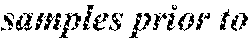
 ,
, .
.
- ,


 ,
, ,
, ,
, ,
,

 .
.
-
- If both numSampL and numSampT are equal to 0, the following applies:
-
- the intra prediction mode predModeIntra,
- a sample location (xTbC, yTbC) of the top-left sample of the current transform block relative to the top-left sample of the current picture,
- a variable nTbW specifying the transform block width,
- a variable nTbH specifying the transform block height,
- a variable cIdx specifying the colour component of the current block,
- chroma neighbouring samples p[x][y], with x=−1, y=0 . . . 2*nTbH−1 and x=0 . . . 2*nTbW−1, y=−1.
Output of this process are predicted samples predSamples[x][y], with x=0 . . . nTbW−1, y=0 . . . nTbH−1.
The current luma location (xTbY, yTbY) is derived as follows:
(xTbY,yTbY)=(xTbC<<(SubWidthC−1),yTbC<<(SubHeightC−1)) (351)
The variables availL, availT and availTL are derived as follows: - The derivation process for neighbouring block availability as specified in clause 6.4.4 is invoked with the current luma location (xCurr, yCurr) set equal to (xTbY, yTbY), the neighbouring luma location (xTbY−1, yTbY), checkPredModeY set equal to FALSE, and cIdx as inputs, and the output is assigned to availL.
- The derivation process for neighbouring block availability as specified in clause 6.4.4 is invoked with the current luma location (xCurr, yCurr) set equal to (xTbY, yTbY), the neighbouring luma location (xTbY, yTbY−1), checkPredModeY set equal to FALSE, and cIdx as inputs, and the output is assigned to availT.
-
 ,
,

-


 ,
,
 ,
, ,
,
 ,
, ,
,

 ,
,

 .
.
-
- ,

 .
.
. . .
The prediction samples predSamples[x][y] with x=0 . . . nTbW−1, y=0 . . . nTbH−1 are derived as follows: - If both numSampL and numSampT are equal to 0, the following applies:
predSamples[x][y]=1<<(BitDepth−1) (359) - Otherwise, the following ordered steps apply:
- 1. The collocated luma samples pY[x][y] with x=0 . . . nTbW*SubWidthC−1, y=0 . . . nTbH*SubHeightC−1 are set equal to the reconstructed luma samples prior to the deblocking filter process at the locations (xTbY+x, yTbY+y).
- 2. The neighbouring luma samples pY[x][y] are derived as follows:
- When numSampL is greater than 0, the neighbouring left luma samples pY[x][y] with x=−1 . . . −3, y=0 . . . SubHeightC*numSampL−1, are set equal to the reconstructed luma samples prior to the deblocking filter process at the locations (xTbY+x, yTbY+y).
- When availT is equal to FALSE, the neighbouring top luma samples pY[x][y] with x=−1 . . . SubWidthC*numSampT−1, y=−1 . . . −2, are set equal to the luma samples pY[x][0].
- When availL is equal to FALSE, the neighbouring left luma samples pY[x][y] with x=−1 . . . −3, y=−1 . . . SubHeightC*numSampL−1, are set equal to the luma samples pY[0][y].
- When numSampT is greater than 0, the neighbouring top luma samples pY[x][y] with x=0 . . . SubWidthC*numSampT−1, y=−1, −2, are set equal to the reconstructed luma samples prior to the deblocking filter process at the locations (xTbY+x, yTbY+y).
- When availTL is equal to TRUE

 , the neighbouring top-left luma samples pY[x][y] with x=−1, y=−1, −2 are set equal to the reconstructed luma samples prior to the deblocking filter process at the locations (xTbY+x, yTbY+y).
-
- If both numSampL and numSampT are equal to 0, the following applies:
predSamples[x][y]=1<<(BitDepth−1) (359) - Otherwise, the following ordered steps apply:
- 1. The collocated luma samples pY[x][y] with x=0 . . . nTbW*SubWidthC−1, y=0 . . . nTbH*SubHeightC−1 are set equal to the reconstructed luma samples prior to the deblocking filter process at the locations (xTbY+x, yTbY+y).
- 2. The neighbouring luma samples pY[x][y] are derived as follows:
- When numSampL is greater than 0, the neighbouring left luma samples pY[x][y] with x=−1 . . . −3, y=0 . . . SubHeightC*numSampL−1, are set equal to the reconstructed luma samples prior to the deblocking filter process at the locations (xTbY+x, yTbY+y).
- When availT is equal to FALSE

 , the neighbouring top luma samples pY[x][y] with x=−1 . . . SubWidthC*numSampT−1, y=−1 . . . −2, are set equal to the luma samples pY[x][0].
- When availL is equal to FALSE

 , the neighbouring left luma samples pY[x][y] with x=−1 . . . −3, y=−1 . . . SubHeightC*numSampL−1, are set equal to the luma samples pY[0][y].
- When numSampT is greater than 0, the neighbouring top luma samples pY[x][y] with x=0 . . . SubWidthC*numSampT−1, y=−1, −2, are set equal to the reconstructed luma samples prior to the deblocking filter process at the locations (xTbY+x, yTbY+y).
- When availTL is equal to TRUE, the neighbouring top-left luma samples pY[x][y] with x=−1, y=−1, −2 are set equal to the reconstructed luma samples prior to the deblocking filter process at the locations (xTbY+x, yTbY+y).
- If both numSampL and numSampT are equal to 0, the following applies:
-
- If both numSampL and numSampT are equal to 0, the following applies:
predSamples[x][y]=1<<(BitDepth−1) (359) - Otherwise, the following ordered steps apply:
- 1. The collocated luma samples pY[x][y] with x=0 . . . nTbW*SubWidthC−1, y=0 . . . nTbH*SubHeightC−1 are set equal to the reconstructed luma samples prior to the deblocking filter process at the locations (xTbY+x, yTbY+y).
- 2. The neighbouring luma samples pY[x][y] are derived as follows:
- When numSampL is greater than 0, the neighbouring left luma samples pY[x][y] with x=−1 . . . −3, y=0 . . . SubHeightC*numSampL−1, are set equal to the reconstructed luma samples prior to the deblocking filter process at the locations (xTbY+x, yTbY+y).
- When availT is equal to FALSE, the neighbouring top luma samples pY[x][y] with x=0 . . . SubWidthC*numSampT−1, y=−1 . . . -2, are set equal to the luma samples pY[x][0].
- When availL is equal to FALSE, the neighbouring left luma samples pY[x][y] with x=−1 . . . −3, y=0 . . . SubHeightC*numSampL−1, are set equal to the luma samples pY[0][y].
- When numSampT is greater than 0, the neighbouring top luma samples pY[x][y] with x=0 . . . SubWidthC*numSampT−1, y=−1, −2, are set equal to the reconstructed luma samples prior to the deblocking filter process at the locations (xTbY+x, yTbY+y).
- When availTL is equal to TRUE, the neighbouring top-left luma samples pY[x][y] with x=−1, y=−1, −2 are set equal to the reconstructed luma samples prior to the deblocking filter process at the locations (xTbY+x, yTbY+y).
- ,


 ,
, ,
, ,
, ,
,
 .
.
- ,

 ,
,


 ,
, ,
, ,
, ,
,
 .
.
- If both numSampL and numSampT are equal to 0, the following applies:
-
- the intra prediction mode predModeIntra,
- a sample location (xTbC, yTbC) of the top-left sample of the current transform block relative to the top-left sample of the current picture,
- a variable nTbW specifying the transform block width,
- a variable nTbH specifying the transform block height,
- a variable cIdx specifying the colour component of the current block,
- chroma neighbouring samples p[x][y], with x=−1, y=0 . . . 2*nTbH−1 and x=0 . . . 2*nTbW−1, y=−1.
Output of this process are predicted samples predSamples[x][y], with x=0 . . . nTbW−1, y=0 . . . nTbH−1.
The current luma location (xTbY, yTbY) is derived as follows:
(xTbY,yTbY)=(xTbC<<(SubWidthC−1),yTbC<<(SubHeightC−1)) (351)
The variables availL, availT and availTL are derived as follows: - The derivation process for neighbouring block availability as specified in clause 6.4.4 is invoked with the current luma location (xCurr, yCurr) set equal to (xTbY, yTbY), the neighbouring luma location (xTbY−1, yTbY), checkPredModeY set equal to FALSE, and cIdx as inputs, and the output is assigned to availL.
- The derivation process for neighbouring block availability as specified in clause 6.4.4 is invoked with the current luma location (xCurr, yCurr) set equal to (xTbY, yTbY), the neighbouring luma location (xTbY, yTbY−1), checkPredModeY set equal to FALSE, and cIdx as inputs, and the output is assigned to availT.
-

 ,
,

-


 ,
,
 ,
, ,
,
 ,
, ,
,
 ,
, ,
,

 .
.
-
- ,

 .
.
. . .
The prediction samples predSamples[x][y] with x=0 . . . nTbW−1, y=0 . . . nTbH−1 are derived as follows: - If both numSampL and numSampT are equal to 0, the following applies:
predSamples[x][y]=1<<(BitDepth−1) (359) - Otherwise, the following ordered steps apply:
- 1. The collocated luma samples pY[x][y] with x=0 . . . nTbW*SubWidthC−1, y=0 . . . nTbH*SubHeightC−1 are set equal to the reconstructed luma samples prior to the deblocking filter process at the locations (xTbY+x, yTbY+y).
- 2. The neighbouring luma samples pY[x][y] are derived as follows:
- When numSampL is greater than 0, the neighbouring left luma samples pY[x][y] with x=−1 . . . −3, y=0 . . . SubHeightC*numSampL−1, are set equal to the reconstructed luma samples prior to the deblocking filter process at the locations (xTbY+x, yTbY+y).
- When availT is equal to FALSE, the neighbouring top luma samples pY[x][y] with x=−1 . . . SubWidthC*numSampT−1, y=−1 . . . −2, are set equal to the luma samples pY[x][0].
- When availL is equal to FALSE, the neighbouring left luma samples pY[x][y] with x=−1 . . . −3, y=−1 . . . SubHeightC*numSampL−1, are set equal to the luma samples pY[0][y].
- When numSampT is greater than 0, the neighbouring top luma samples pY[x][y] with x=0 . . . SubWidthC*numSampT−1, y=−1, −2, are set equal to the reconstructed luma samples prior to the deblocking filter process at the locations (xTbY+x, yTbY+y).
-
 ,
,

-
 ,
,


 ,
, ,
, ,
,


 ,
, .
.
- ,


 ,
, ,
, ,
, ,
,

 .
.
-
-
- the intra prediction mode predModeIntra,
- a sample location (xTbC, yTbC) of the top-left sample of the current transform block relative to the top-left sample of the current picture,
- a variable nTbW specifying the transform block width,
- a variable nTbH specifying the transform block height,
- a variable cIdx specifying the colour component of the current block,
- chroma neighbouring samples p[x][y], with x=−1, y=0 . . . 2*nTbH−1 and x=0 . . . 2*nTbW−1, y=−1.
Output of this process are predicted samples predSamples[x][y], with x=0 . . . nTbW−1, y=0 . . . nTbH−1.
The current luma location (xTbY, yTbY) is derived as follows:
(xTbY,yTbY)=(xTbC<<(SubWidthC−1),yTbC<<(SubHeightC−1)) (351)
The variables availL, availT and availTL are derived as follows: - The derivation process for neighbouring block availability as specified in clause 6.4.4 is invoked with the current luma location (xCurr, yCurr) set equal to (xTbY, yTbY), the neighbouring luma location (xTbY−1, yTbY), checkPredModeY set equal to FALSE, and cIdx as inputs, and the output is assigned to availL.
- The derivation process for neighbouring block availability as specified in clause 6.4.4 is invoked with the current luma location (xCurr, yCurr) set equal to (xTbY, yTbY), the neighbouring luma location (xTbY, yTbY−1), checkPredModeY set equal to FALSE, and cIdx as inputs, and the output is assigned to availT.
-

 ,
,

-


 ,
,
 ,
, ,
,
 ,
, ,
,
 ,
, ,
,
 .
.
-
- ,
 .
.
. . .
The prediction samples predSamples[x][y] with x=0 . . . nTbW−1, y=0 . . . nTbH−1 are derived as follows: - If both numSampL and numSampT are equal to 0, the following applies:
predSamples[x][y]=1<<(BitDepth−1) (359) - Otherwise, the following ordered steps apply:
- 1. The collocated luma samples pY[x][y] with x=0 . . . nTbW*SubWidthC−1, y=0 . . . nTbH*SubHeightC−1 are set equal to the reconstructed luma samples prior to the deblocking filter process at the locations (xTbY+x, yTbY+y).
- 2. The neighbouring luma samples pY[x][y] are derived as follows:
- When numSampL is greater than 0, the neighbouring left luma samples pY[x][y] with x=−1 . . . −3, y=0 . . . SubHeightC*numSampL−1, are set equal to the reconstructed luma samples prior to the deblocking filter process at the locations (xTbY+x, yTbY+y).
- When availT is equal to FALSE, the neighbouring top luma samples pY[x][y] with x=−1 . . . SubWidthC*numSampT−1, y=−1 . . . −2, are set equal to the luma samples pY[x][0].
- When availL is equal to FALSE, the neighbouring left luma samples pY[x][y] with x=−1 . . . −3, y=−1 . . . SubHeightC*numSampL−1, are set equal to the luma samples pY[0][y].
- When numSampT is greater than 0, the neighbouring top luma samples pY[x][y] with x=0 . . . SubWidthC*numSampT−1, y=−1, −2, are set equal to the reconstructed luma samples prior to the deblocking filter process at the locations (xTbY+x, yTbY+y).
-
 ,
,

- ,


 ,
, ,
, ,
,


 ,
, .
.
- ,


 ,
, ,
, ,
, ,
,

 .
.
-
-
- the intra prediction mode predModeIntra,
- a sample location (xTbC, yTbC) of the top-left sample of the current transform block relative to the top-left sample of the current picture,
- a variable nTbW specifying the transform block width,
- a variable nTbH specifying the transform block height,
- a variable cIdx specifying the colour component of the current block,
- chroma neighbouring samples p[x][y], with x=−1, y=0 . . . 2*nTbH−1 and x=0 . . . 2*nTbW−1, y=−1.
Output of this process are predicted samples predSamples[x][y], with x=0 . . . nTbW−1, y=0 . . . nTbH−1.
The current luma location (xTbY, yTbY) is derived as follows:
(xTbY,yTbY)=(xTbC<<(SubWidthC−1),yTbC<<(SubHeightC−1)) (351)
The variables availL, availT and availTL are derived as follows: - The derivation process for neighbouring block availability as specified in clause 6.4.4 is invoked with the current luma location (xCurr, yCurr) set equal to (xTbY, yTbY), the neighbouring luma location (xTbY−1, yTbY), checkPredModeY set equal to FALSE, and cIdx as inputs, and the output is assigned to availL.
- The derivation process for neighbouring block availability as specified in clause 6.4.4 is invoked with the current luma location (xCurr, yCurr) set equal to (xTbY, yTbY), the neighbouring luma location (xTbY, yTbY−1), checkPredModeY set equal to FALSE, and cIdx as inputs, and the output is assigned to availT.
-


 .
. .
.


 ,
, ,
,

 ,
, ,
,
 ,
, ,
,
 .
.
. . .
The prediction samples predSamples[x][y] with x=0 . . . nTbW−1, y=0 . . . nTbH−1 are derived as follows: - If both numSampL and numSampT are equal to 0, the following applies:
predSamples[x][y]=1<<(BitDepth−1) (359) - Otherwise, the following ordered steps apply:
- 1. The collocated luma samples pY[x][y] with x=0 . . . nTbW*SubWidthC−1, y=0 . . . nTbH*SubHeightC−1 are set equal to the reconstructed luma samples prior to the deblocking filter process at the locations (xTbY+x, yTbY+y).
- 2. The neighbouring luma samples pY[x][y] are derived as follows:
- When numSampL is greater than 0, the neighbouring left luma samples pY[x][y] with x=−1 . . . −3, y=0 . . . SubHeightC*numSampL−1, are set equal to the reconstructed luma samples prior to the deblocking filter process at the locations (xTbY+x, yTbY+y).
- When availT is equal to FALSE, the neighbouring top luma samples pY[x][y] with x=−1 . . . SubWidthC*numSampT−1, y=−1 . . . −2, are set equal to the luma samples pY[x][0].
- When availL is equal to FALSE, the neighbouring left luma samples pY[x][y] with x=−1 . . . −3, y=−1 . . . SubHeightC*numSampL−1, are set equal to the luma samples pY[0][y].
- When numSampT is greater than 0, the neighbouring top luma samples pY[x][y] with x=0 . . . SubWidthC*numSampT−1, y=−1, −2, are set equal to the reconstructed luma samples prior to the deblocking filter process at the locations (xTbY+x, yTbY+y).
-
 ,
,

-
 ,
,

 ,
, ,
, ,
,


 ,
, .
.
- ,


 ,
, ,
, ,
, ,
,

 .
.
-
-
- the intra prediction mode predModeIntra,
- a sample location (xTbC, yTbC) of the top-left sample of the current transform block relative to the top-left sample of the current picture,
- a variable nTbW specifying the transform block width,
- a variable nTbH specifying the transform block height,
- a variable cIdx specifying the colour component of the current block,
- chroma neighbouring samples p[x][y], with x=−1, y=0 . . . 2*nTbH−1 and x=0 . . . 2*nTbW−1, y=−1.
Output of this process are predicted samples predSamples[x][y], with x=0 . . . nTbW−1, y=0 . . . nTbH−1.
The current luma location (xTbY, yTbY) is derived as follows:
(xTbY,yTbY)=(xTbC<<(SubWidthC−1),yTbC<<(SubHeightC−1)) (351)
The variables availL, availT and availTL are derived as follows: - The derivation process for neighbouring block availability as specified in clause 6.4.4 is invoked with the current luma location (xCurr, yCurr) set equal to (xTbY, yTbY), the neighbouring luma location (xTbY−1, yTbY), checkPredModeY set equal to FALSE, and cIdx as inputs, and the output is assigned to availL.
- The derivation process for neighbouring block availability as specified in clause 6.4.4 is invoked with the current luma location (xCurr, yCurr) set equal to (xTbY, yTbY), the neighbouring luma location (xTbY, yTbY−1), checkPredModeY set equal to FALSE, and cIdx as inputs, and the output is assigned to availT.
-


 ,
,
 ,
, ,
,

 ,
, ,
,
 ,
, ,
,
 .
.
. . .
The prediction samples predSamples[x][y] with x=0 . . . nTbW−1, y=0 . . . nTbH−1 are derived as follows: - If both numSampL and numSampT are equal to 0, the following applies:
predSamples[x][y]=1<<(BitDepth−1) (359) - Otherwise, the following ordered steps apply:
- 1. The collocated luma samples pY[x][y] with x=0 . . . nTbW*SubWidthC−1, y=0 . . . nTbH*SubHeightC−1 are set equal to the reconstructed luma samples prior to the deblocking filter process at the locations (xTbY+x, yTbY+y).
- 2. The neighbouring luma samples pY[x][y] are derived as follows:
- When numSampL is greater than 0, the neighbouring left luma samples pY[x][y] with x=−1 . . . −3, y=0 . . . SubHeightC*numSampL−1, are set equal to the reconstructed luma samples prior to the deblocking filter process at the locations (xTbY+x, yTbY+y).
- When availT is equal to FALSE, the neighbouring top luma samples pY[x][y] with x=−1 . . . SubWidthC*numSampT−1, y=−1 . . . −2, are set equal to the luma samples pY[x][0].
- When availL is equal to FALSE, the neighbouring left luma samples pY[x][y] with x=−1 . . . −3, y=−1 . . . SubHeightC*numSampL−1, are set equal to the luma samples pY[0][y].
- When numSampT is greater than 0, the neighbouring top luma samples pY[x][y] with x=0 . . . SubWidthC*numSampT−1, y=−1, −2, are set equal to the reconstructed luma samples prior to the deblocking filter process at the locations (xTbY+x, yTbY+y).
-
 ,
,

-
 ,
,


 ,
, ,
, ,
,


 ,
, .
.
- ,


 ,
, ,
, ,
, ,
,

 .
.
-
-
- If both numSampL and numSampT are equal to 0, the following applies:
predSamples[x][y]=1<<(BitDepth−1) (359) - Otherwise, the following ordered steps apply:
- 1. The collocated luma samples pY[x][y] with x=0 . . . nTbW*SubWidthC−1, y=0 . . . nTbH*SubHeightC−1 are set equal to the reconstructed luma samples prior to the deblocking filter process at the locations (xTbY+x, yTbY+y).
- 2. The neighbouring luma samples pY[x][y] are derived as follows:
- When numSampL is greater than 0, the neighbouring left luma samples pY[x][y] with x=−1 . . . −3, y=0 . . . SubHeightC*numSampL−1, are set equal to the reconstructed luma samples prior to the deblocking filter process at the locations (xTbY+x, yTbY+y).
- When availT is equal to FALSE, the neighbouring top luma samples pY[x][y] with x=−1 . . . SubWidthC*numSampT−1, y=−1 . . . −2, are set equal to the luma samples pY[x][0].
- When availL is equal to FALSE, the neighbouring left luma samples pY[x][y] with x=−1 . . . −3, y=−1 . . . SubHeightC*numSampL−1, are set equal to the luma samples pY[0][y].
- When numSampT is greater than 0, the neighbouring top luma samples pY[x][y] with x=0 . . . SubWidthC*numSampT−1, y=−1, −2, are set equal to the reconstructed luma samples prior to the deblocking filter process at the locations (xTbY+x, yTbY+y).
- When availTL is equal to TRUE, the neighbouring top-left luma samples pY[x][y] with x=−1, y=−1, −2 are set equal to the reconstructed luma samples prior to the deblocking filter process at the locations (xTbY+x, yTbY+y).
- 3. The down-sampled collocated luma samples pDsY[x][y] with x=0 . . . nTbW−1, y=0 . . . nTbH−1 are derived as follows:
- If both SubWidthC and SubHeightC are equal to 1, the following applies:
- pDsY[x][y] with x=1 . . . nTbW−1, y=1 . . . nTbH−1 is derived as follows:
pDstY[x][y]=pY[x][y] (360)
- pDsY[x][y] with x=1 . . . nTbW−1, y=1 . . . nTbH−1 is derived as follows:
- Otherwise, the following applies:
- The one-dimensional filter coefficients array F1 and F2, and the 2-dimensional filter coefficients arrays F3 and F4 are specified as follows.
F1[0]=2,F1[1]=0 (361)
F2[0]=1,F2[1]=2,F2[2]=1 (362)
F3[i][j]=F4[i][j]=0,with i=0 . . . 2,j=0 . . . 2 (363) - If both SubWidthC and SubHeightC are equal to 2, the following applies:
F1[0]=1,F1[1]=1 (364)
F3[0][1]=1,F3[1][1]=4,F3[2][1]=1,F3[1][0]=1,F3[1][2]=1 (365)
F4[0][1]=1,F4[1][1]=2,F4[2][1]=1 (366)
F4[0][2]=1,F4[1][2]=2,F4[2][2]=1 (367) - Otherwise, the following applies:
,F3[1][1]= ,
, , (368)
F4[0][1]=2,F4[1][1]=4,F4[2][1]=2, (369) - If sps_chromavertical_collocated_flag is equal to 1, the following applies:
- pDsY[x][y] with x=0 . . . nTbW−1, y=0 . . . nTbH−1 is derived as follows:
pDsY[x][y]=(F3[1][0]*pY[SubWidthC*x][SubHeightC*y−1]+F3[0][1]*pY[SubWidthC*x−1][SubHeightC*y]+F3[1][1]*pY[SubWidthC*x][SubHeightC*y]+F3[2][1]*pY[SubWidthC*x+1][SubHeightC*y]+F3[1][2]*pY[SubWidthC*x][SubHeightC*y+1]+4)>>3 (370) - Otherwise (sps_chroma_vertical_collocated_flag is equal to 0), the following applies:
- pDsY[x][y] with x=0 . . . nTbW−1, y=0 . . . nTbH−1 is derived as follows:
pDsY[x][y]=(F4[0][1]*pY[SubWidthC*x−1][SubHeightC*y]+F4[0][2]*pY[SubWidthC*x−1][SubHeightC*y+1]+F4[1][1]*pY[SubWidthC*x][SubHeightC*y]+F4[1][2]*pY[SubWidthC*x][SubHeightC*y+1]+F4[2][1]*pY[SubWidthC*x+1][SubHeightC*y]+F4[2][2]*pY[SubWidthC*x+1][SubHeightC*y+1]+4)>>3 (371)
- The one-dimensional filter coefficients array F1 and F2, and the 2-dimensional filter coefficients arrays F3 and F4 are specified as follows.
- If both SubWidthC and SubHeightC are equal to 1, the following applies:
- If both numSampL and numSampT are equal to 0, the following applies:
-
- the intra prediction mode predModeIntra,
- a sample location (xTbC, yTbC) of the top-left sample of the current transform block relative to the top-left sample of the current picture,
- a variable nTbW specifying the transform block width,
- a variable nTbH specifying the transform block height,
- a variable cIdx specifying the colour component of the current block,
- chroma neighbouring samples p[x][y], with x=−1, y=0 . . . 2*nTbH−1 and x=0 . . . 2*nTbW−1, y=−1.
Output of this process are predicted samples predSamples[x][y], with x=0 . . . nTbW−1, y=0 . . . nTbH−1.
The current luma location (xTbY, yTbY) is derived as follows:
(xTbY,yTbY)=(xTbC<<(SubWidthC−1),yTbC<<(SubHeightC−1)) (351)
The variables availL, availT and availTL are derived as follows: - The derivation process for neighbouring block availability as specified in clause 6.4.4 is invoked with the current luma location (xCurr, yCurr) set equal to (xTbY, yTbY), the neighbouring luma location (xTbY−1, yTbY), checkPredModeY set equal to FALSE, and cIdx as inputs, and the output is assigned to availL.
- The derivation process for neighbouring block availability as specified in clause 6.4.4 is invoked with the current luma location (xCurr, yCurr) set equal to (xTbY, yTbY), the neighbouring luma location (xTbY, yTbY−1), checkPredModeY set equal to FALSE, and cIdx as inputs, and the output is assigned to availT.
- The variable availTL is derived as follows:
availTL=availL&&availT (352) - The number of available top-right neighbouring chroma samples numTopRight is derived as follows:
- The variable numTopRight is set equal to 0 and availTR is set equal to TRUE.
- When predModeIntra is equal to INTRA_T_CCLM, the following applies for x=nTbW . . . 2*nTbW−1 until availTR is equal to FALSE or x is equal to 2*nTbW−1:
- The derivation process for neighbouring block availability as specified in clause 6.4.4 is invoked with the current luma location (xCurr, yCurr) set equal to (xTbY, yTbY) the neighbouring luma location (xTbY+x, yTbY−1), checkPredModeY set equal to FALSE, and cIdx as inputs, and the output is assigned to availTR
- When availTR is equal to TRUE, numTopRight is incremented by one.
- The number of available left-below neighbouring chroma samples numLeftBelow is derived as follows:
- The variable numLeftBelow is set equal to 0 and availLB is set equal to TRUE.
- When predModeIntra is equal to INTRA_L_CCLM, the following applies for y=nTbH . . . 2*nTbH−1 until availLB is equal to FALSE or y is equal to 2*nTbH−1:
- The derivation process for neighbouring block availability as specified in clause 6.4.4 is invoked with the current luma location (xCurr, yCurr) set equal to (xTbY, yTbY), the neighbouring luma location (xTbY−1, yTbY+y), checkPredModeY set equal to FALSE, and cIdx as inputs, and the output is assigned to availLB
- When availLB is equal to TRUE, numLeftBelow is incremented by one.
The number of available neighbouring chroma samples on the top and top-right numSampT and the number of available neighbouring chroma samples on the left and left-below numSampL are derived as follows:
- If predModeIntra is equal to INTRA_LT_CCLM, the following applies:
numSampT=availT?nTbW:0 (353)
numSampL=availL?nTbH:0 (354) - Otherwise, the following applies:
numSampT=(availT&&predModeIntra==INTRA_T_CCLM)?(nTbW+Min(numTopRight,nTbH)):0 (355)
numSampL=(availL&&predModeIntra==INTRA_L_CCLM)?(nTbH+Min(numLeftBelow,nTbW)):0 (356)
The variable bCTUboundary is derived as follows:
bCTUboundary=(yTbY&(CtbSizeY−1)==0)?TRUE:FALSE. (357)
The variable cntN and array pickPosN with N being replaced by L and T, are derived as follows: - The variable numIs4N is derived as follows:
numIs4N=((availT&&availL&&predModeIntra==INTRA_LT_CCLM)?0:1) (358) - The variable startPosN is set equal to numSampN>>(2+numIs4N).
- The variable pickStepN is set equal to Max(1, numSampN>>(1+numIs4N)).
- If availN is equal to TRUE and predModeIntra is equal to INTRA_LT_CCLM or INTRA_N_CCLM, the following assignments are made:
- cntN is set equal to Min(numSampN, (1+numIs4N)<<1).
- pickPosN[pos] is set equal to (startPosN+pos*pickStepN), with pos=0 . . . cntN−1.
- Otherwise, cntN is set equal to 0.
 .
.
The prediction samples predSamples[x][y] with x=0 . . . nTbW−1, y=0 . . . nTbH−1 are derived as follows: - If both numSampL and numSampT are equal to 0, the following applies:
predSamples[x][y]=1<<(BitDepth−1) (359) - Otherwise, the following ordered steps apply:
- 1. The collocated luma samples pY[x][y] with x=0 . . . nTbW*SubWidthC−1, y=0 . . . nTbH*SubHeightC−1 are set equal to the reconstructed luma samples prior to the deblocking filter process at the locations (xTbY+x, yTbY+y).
- 2. The neighbouring luma samples pY[x][y] are derived as follows:
- When numSampL is greater than 0, the neighbouring left luma samples pY[x][y] with x=−1 . . . −3, y=0 . . . SubHeightC*numSampL−1, are set equal to the reconstructed luma samples prior to the deblocking filter process at the locations (xTbY+x, yTbY+y).
- When availT is equal to FALSE, the neighbouring top luma samples pY[x][y] with x=−1 . . . SubWidthC*numSampT−1, y=−1 . . . −2, are set equal to the luma samples pY[x][0].
- When availL is equal to FALSE, the neighbouring left luma samples pY[x][y] with x=−1 . . . −3, y=−1 . . . SubHeightC*numSampL−1, are set equal to the luma samples pY[0][y].
- When numSampT is greater than 0, the neighbouring top luma samples pY[x][y] with x=0 . . . SubWidthC*numSampT−1, y=−1, −2, are set equal to the reconstructed luma samples prior to the deblocking filter process at the locations (xTbY+x, yTbY+y).
- When availTL is equal to TRUE, the neighbouring top-left luma samples pY[x][y] with x=−1, y=−1, −2, are set equal to the reconstructed luma samples prior to the deblocking filter process at the locations (xTbY+x, yTbY+y).
- 3. The down-sampled collocated luma samples pDsY[x][y] with x=0 . . . nTbW−1, y=0 . . . nTbH−1 are derived as follows:
- If both SubWidthC and SubHeightC are equal to 1, the following applies:
- pDsY[x][y] with x=1 . . . nTbW−1, y=1. nTbH−1 is derived as follows:
pDstY[x][y]=pY[x][y] (360)
- pDsY[x][y] with x=1 . . . nTbW−1, y=1. nTbH−1 is derived as follows:
- Otherwise, the following applies:
- The one-dimensional filter coefficients array F1 and F2, and the 2-dimensional filter coefficients arrays F3 and F4 are specified as follows.
F1[0]=2,F1[1]=0 (361)
F2[0]=1,F2[1]=2,F2[2]=1 (362)
F3[i][j]=F4[i][j]=0,with i=0 . . . 2,j=0 . . . 2 (363) - If both SubWidthC and SubHeightC are equal to 2, the following applies:
F1[0]=1,F1[1]=1 (364)
F3[0][1]=1,F3[1][1]=4,F3[2][1]=1,F3[1][0]=1,F3[2]=1 (365)
F4[0][1]=1,F4[1][1]=2,F4[2][1]=1 (366)
F4[0][2]=1,F4[1][2]=2,F4[2][2]=1 (367) -


- Otherwise, the following applies:
F3[1][1]=8 (368)
F4[0][1]=2,F4[1][1]=4,F4[2][1]=2, (369) -

- If is equal to 1, the following applies:

- pDsY[x][y] with x=0 . . . nTbW−1, y=0 . . . nTbH−1 is derived as follows:
pDsY[x][y]=(F3[1][0]*pY[SubWidthC*x][SubHeightC*y−1]+F3[0][1]*pY[SubWidthC*x−1][SubHeightC*y]+F3[1][1]*pY[SubWidthC*x][SubHeightC*y]+F3[2][1]*pY[SubWidthC*x+1][SubHeightC*y]+F3[1][2]*pY[SubWidthC*x][SubHeightC*y+1]+4)>>3 (371) - Otherwise (is equal to 0), the following applies:

- pDsY[x][y] with x=0 . . . nTbW−1, y=0 . . . nTbH−1 is derived as follows:
pDsY[x][y]=(F4[0][1]*pY[SubWidthC*x−1][SubHeightC*y]+F4[0][2]*pY[SubWidthC*x−1][SubHeightC*y+1]+F4[1][1]*pY[SubWidthC*x][SubHeightC*y]+F4[1][2]*pY[SubWidthC*x][SubHeightC*y+1]+F4[2][1]*pY[SubWidthC*x+1][SubHeightC*y]+F4[2][2]*pY[SubWidthC*x+1][SubHeightC*y+1]+4)>>3 (371)
- The one-dimensional filter coefficients array F1 and F2, and the 2-dimensional filter coefficients arrays F3 and F4 are specified as follows.
- If both SubWidthC and SubHeightC are equal to 1, the following applies:
- 4. When numSampL is greater than 0, the selected neighbouring left chroma samples pSelC[idx] are set equal to p[−1][pickPosL[idx]] with idx=0 . . . cntL−1, and the selected down-sampled neighbouring left luma samples pSelDsY[idx] with idx=0 . . . cntL−1 are derived as follows:
- The variable y is set equal to pickPosL[idx].
- If both SubWidthC and SubHeightC are equal to 1, the following applies:
pSelDsY[idx]=pY[−1][y] (372) - Otherwise the following applies:
- If is equal to 1, the following applies:

pSelDsY[idx]=(F3[1][0]*pY[−SubWidthC][SubHeightC*y−1]+F3[0][1]*pY[−1−SubWidthC][SubHeightC*y]+F3[1][1]*pY[−SubWidthC][SubHeightC*y]+F3[2][1]*pY[1−SubWidthC][SubHeightC*y]+F3[1][2]*pY[−SubWidthC][SubHeightC*y+1]+4)>>3 (373) - Otherwise (is equal to 0), the following applies:

pSelDsY[idx]=(F4[0][1]*pY[−1−SubWidthC][SubHeightC*y]+F4[0][2]*pY[−1−SubWidthC][SubHeightC*y]+1+F4[1][1]*pY[−SubWidthC][SubHeightC*y]+F4[1][2]*pY[−SubWidthC][SubHeightC*y+1]+F4[2][1]*pY[1−SubWidthC][SubHeightC*y]+F4[2][2]*pY[1−SubWidthC][SubHeightC*y+1]+4)>>3 (374)
- If
- 5. When numSampT is greater than 0, the selected neighbouring top chroma samples pSelC[idx] are set equal to p[pickPosT[idx−cntL]][−1] with idx=cntL . . . cntL+cntT−1, and the down-sampled neighbouring top luma samples pSelDsY[idx] with idx=. . . cntL+cntT−1 are specified as follows:

- The variable x is set equal to pickPosT[idx−cntL].
- If both SubWidthC and SubHeightC are equal to 1, the following applies:
pSelDsY[idx]=pY[x][−1] (375) - Otherwise, the following applies:
- If is equal to 1, the following applies:

- If bCTUboundary is equal to FALSE, the following applies:
pSelDsY[idx]=(F3[1][0]*pY[SubWidthC*x][−1−SubHeightC]+F3[0][1]*pY[SubWidthC*x−1][−SubHeightC]+F3[1][1]*pY[SubWidthC*x][−SubHeightC]+F3[2][1]*pY[SubWidthC*x+1][−SubHeightC]+F3[1][2]*pY[SubWidthC*x][1−SubHeightC]+4)>>3 (376) - Otherwise (bCTUboundary is equal to TRUE), the following applies:
pSelDsY[idx]=(F2[0]*pY[SubWidthC*x−1][−1]+F2[1]*pY[SubWidthC*x][−1]+F2[2]*pY[SubWidthC*x+1][−1]+2)>>2 (377) - Otherwise (is equal to 0), the following applies:

- If bCTUboundary is equal to FALSE, the following applies:
pSelDsY[idx]=(F4[0][1]*pY[SubWidthC x−1][−1]+F4[0][2]*pY[SubWidthC*x−1][−2]+F4[1][1]*pY[SubWidthC*x][−1]+F4[1][2]*pY[SubWidthC*x][−2]+F4[2][1]*pY[SubWidthC*x+1][−1]+F4[2][2]*pY[SubWidthC*x+1][−2]+4)>>3 (378) - Otherwise (bCTUboundary is equal to TRUE), the following applies:
pSelDsY[idx]=(F2[0]*pY[SubWidthC*x−1][−1]+F2[1]*pY[SubWidthC*x][−1]+F2[2]*pY[SubWidthC*x+1][−1]+2)>>2 (379)
- If
- 6. When cntT+cntL is not equal to 0, the variables minY, maxY, minC and maxC are derived as follows:
- When cntT+cntL is equal to 2, pSelComp[3] is set equal to pSelComp[0], pSelComp[2] is set equal to pSelComp[1], pSelComp[0] is set equal to pSelComp[1], and pSelComp[1] is set equal to pSelComp[3], with Comp being replaced by DsY and C.
- The arrays minGrpIdx and maxGrpIdx are derived as follows:
minGrpIdx[0]=0 (380)
minGrpIdx[1]=2 (381)
maxGrpIdx[0]=1 (382)
maxGrpIdx[1]=3 (383) - When pSelDsY[minGrpIdx[0]] is greater than pSelDsY[minGrpIdx[1]], minGrpIdx[0] and minGrpIdx[1] are swapped as follows:
(minGrpIdx[0],minGrpIdx[1])=Swap(minGrpIdx[0],minGrpIdx[1]) (384) - When pSelDsY[maxGrpIdx[0]] is greater than pSelDsY[maxGrpIdx[1]], maxGrpIdx[0] and maxGrpIdx[1] are swapped as follows:
(maxGrpIdx[0],maxGrpIdx[1])=Swap(maxGrpIdx[0],maxGrpIdx[1]) (385) - When pSelDsY[minGrpIdx[0]] is greater than pSelDsY[maxGrpIdx[1]], arrays minGrpIdx and maxGrpIdx are swapped as follows:
(minGrpIdx,maxGrpIdx)=Swap(minGrpIdx,maxGrpIdx) (386) - When pSelDsY[minGrpIdx[1]] is greater than pSelDsY[maxGrpIdx[0]], minGrpIdx[1] and maxGrpIdx[0] are swapped as follows:
(minGrpIdx[1],maxGrpIdx[0])=Swap(minGrpIdx[1],maxGrpIdx[0]) (387) - The variables maxY, maxC, minY and minC are derived as follows:
maxY=(pSelDsY[maxGrpIdx[0]]+pSelDsY[maxGrpIdx[1]]+1)>>1 (388)
maxC=(pSelC[maxGrpIdx[0]]+pSelC[maxGrpIdx[1]]+1)>>1 (389)
minY=(pSelDsY[minGrpIdx[0]]+pSelDsY[minGrpIdx[1]]+1)>>1 (390)
minC=(pSelC[minGrpIdx[0]]+pSelC[minGrpIdx[1]]+1)>>1 (391)
- 7. The variables a, b, and k are derived as follows:
- If numSampL is equal to 0, and numSampT is equal to 0, the following applies:
k=0 (392)
a=0 (393)
b=1<<(BitDepth−1) (394) - Otherwise, the following applies:
diff=maxY−minY (395)- If diff is not equal to 0, the following applies:
diffC=maxC−minC (396)
x=Floor(Log 2(diff)) (397)
normDiff=((diff<<4)>>x)&15 (398)
x+=(normDiff !=0)?1:0 (399)
y=Abs(diffC)>0?Floor(Log 2(Abs(diffC)))+1:0 (400)
a=(diffC*(divSigTable[normDiff]|8)+2y-1)>>y (401)
k=((3+x−y)<1)?1:3+x−y (402)
a=((3+x−y)<1)?Sign(a)*15:a (403)
b=minC−((a*minY)>>k) (404) - where divSigTable[ ] is specified as follows:
divSigTable[ ]={0,7,6,5,5,4,4,3,3,2,2,1,1,1,1,0} (405) - Otherwise (diff is equal to 0), the following applies:
k=0 (406)
a=0 (407)
b=minC (408)
- If diff is not equal to 0, the following applies:
- If numSampL is equal to 0, and numSampT is equal to 0, the following applies:
- 8. The prediction samples predSamples[x][y] with x=0 . . . nTbW−1, y=0 . . . nTbH−1 are derived as follows:
predSamples[x][y]=Clip1(((pDsY[x][y]*a)>>k)+b) (409)
- NOTE—This process uses sps_chroma_vertical_collocated_flag. However, in order to simplify implementation, it does not use sps_chroma_horizontal_collocated_flag.
-
- If both numSampL and numSampT are equal to 0, the following applies:
predSamples[x][y]=1<<(BitDepth−1) (359) - Otherwise, the following ordered steps apply:
- 1. The collocated luma samples pY[x][y] with x=0 . . . nTbW*SubWidthC−1, y=0 . . . nTbH*SubHeightC−1 are set equal to the reconstructed luma samples prior to the deblocking filter process at the locations (xTbY+x, yTbY+y).
- 2. The neighbouring luma samples pY[x][y] are derived as follows:
- When
 , the neighbouring left luma samples pY[x][y] with x=−1 . . . −3, y=0 . . . SubHeightC*max(numSampL,
 −1, are set equal to the reconstructed luma samples prior to the deblocking filter process at the locations (xTbY+x, yTbY+y).
- When availT is equal to FALSE, the neighbouring top luma samples pY[x][y] with x=−1 . . . SubWidthC*numSampT−1, y=−1 . . . −2, are set equal to the luma samples pY[x][0].
- When availL is equal to FALSE, the neighbouring left luma samples pY[x][y] with x=−1 . . . −3, y=−1 . . . SubHeightC*numSampL−1, are set equal to the luma samples pY[0][y].
- When
 , the neighbouring top luma samples pY[x][y] with x=0 . . . SubWidthC*max(numSampT,
 −1, y=−1, −2, are set equal to the reconstructed luma samples prior to the deblocking filter process at the locations (xTbY+x, yTbY+y).
- When availTL is equal to TRUE, the neighbouring top-left luma samples pY[x][y] with x=−1, y=−1, −2 are set equal to the reconstructed luma samples prior to the deblocking filter process at the locations (xTbY+x, yTbY+y).
- When
- If both numSampL and numSampT are equal to 0, the following applies:
-
- If both numSampL and numSampT are equal to 0, the following applies:
predSamples[x][y]=1<<(BitDepth−1) (359) - Otherwise, the following ordered steps apply:
- 1. The collocated luma samples pY[x][y] with x=0 . . . nTbW*SubWidthC−1, y=0 . . . nTbH*SubHeightC−1 are set equal to the reconstructed luma samples prior to the deblocking filter process at the locations (xTbY+x, yTbY+y).
- 2. The neighbouring luma samples pY[x][y] are derived as follows:
- When numSampL is greater than 0, the neighbouring left luma samples pY[x][y] with x=−1 . . . −3, y=0 . . . SubHeightC*numSampL−1, are set equal to the reconstructed luma samples prior to the deblocking filter process at the locations (xTbY+x, yTbY+y).
-

 ,
,

 ,
, ,
,


 ,
, .
.
- When availT is equal to FALSE, the neighbouring top luma samples pY[x][y] with x=−1 . . . SubWidthC*numSampT−1, y=−1 . . . −2, are set equal to the luma samples pY[x][0].
- When availL is equal to FALSE, the neighbouring left luma samples pY[x][y] with x=−1 . . . −3, y=−1 . . . SubHeightC*numSampL−1, are set equal to the luma samples pY[0][y].
- When numSampT is greater than 0, the neighbouring top luma samples pY[x][y] with x=0 . . . SubWidthC*numSampT−1, y=−1, −2, are set equal to the reconstructed luma samples prior to the deblocking filter process at the locations (xTbY+x, yTbY+y).
-

 ,
,


 ,
, ,
,


 ,
, .
.
- When availTL is equal to TRUE, the neighbouring top-left luma samples pY[x][y] with x=−1, y=−1, −2 are set equal to the reconstructed luma samples prior to the deblocking filter process at the locations (xTbY+x, yTbY+y).
- If both numSampL and numSampT are equal to 0, the following applies:
-
- the intra prediction mode predModeIntra,
- a sample location (xTbC, yTbC) of the top-left sample of the current transform block relative to the top-left sample of the current picture,
- a variable nTbW specifying the transform block width,
- a variable nTbH specifying the transform block height,
- a variable cIdx specifying the colour component of the current block,
- chroma neighbouring samples p[x][y], with x=−1, y=0 . . . 2*nTbH−1 and x=0 . . . 2*nTbW−1, y=−1.
Output of this process are predicted samples predSamples[x][y], with x=0 . . . nTbW−1, y=0 . . . nTbH−1.
The current luma location (xTbY, yTbY) is derived as follows:
(xTbY,yTbY)=(xTbC<<(SubWidthC−1),yTbC<<(SubHeightC−1)) (351)
The variables availL, availT and availTL are derived as follows: - The derivation process for neighbouring block availability as specified in clause 6.4.4 is invoked with the current luma location (xCurr, yCurr) set equal to (xTbY, yTbY), the neighbouring luma location (xTbY−1, yTbY), checkPredModeY set equal to FALSE, and cIdx as inputs, and the output is assigned to availL.
- The derivation process for neighbouring block availability as specified in clause 6.4.4 is invoked with the current luma location (xCurr, yCurr) set equal to (xTbY, yTbY), the neighbouring luma location (xTbY, yTbY−1), checkPredModeY set equal to FALSE, and cIdx as inputs, and the output is assigned to availT.
- The variable availTL is derived as follows:
availTL=availL&&availT (352) - The number of available top-right neighbouring chroma samples numTopRight is derived as follows:
- The variable numTopRight is set equal to 0 and availTR is set equal to TRUE.
- When predModeIntra is equal to INTRA_T_CCLM, the following applies for x=nTbW . . . 2*nTbW−1 until availTR is equal to FALSE or x is equal to 2*nTbW−1:
- The derivation process for neighbouring block availability as specified in clause 6.4.4 is invoked with the current luma location (xCurr, yCurr) set equal to (xTbY, yTbY) the neighbouring luma location (xTbY+x, yTbY−1), checkPredModeY set equal to FALSE, and cIdx as inputs, and the output is assigned to availTR
- When availTR is equal to TRUE, numTopRight is incremented by one.
- The number of available left-below neighbouring chroma samples numLeftBelow is derived as follows:
- The variable numLeftBelow is set equal to 0 and availLB is set equal to TRUE.
- When predModeIntra is equal to INTRA_L_CCLM, the following applies for y=nTbH . . . 2*nTbH−1 until availLB is equal to FALSE or y is equal to 2*nTbH−1:
- The derivation process for neighbouring block availability as specified in clause 6.4.4 is invoked with the current luma location (xCurr, yCurr) set equal to (xTbY, yTbY), the neighbouring luma location (xTbY−1, yTbY+y), checkPredModeY set equal to FALSE, and cIdx as inputs, and the output is assigned to availLB
- When availLB is equal to TRUE, numLeftBelow is incremented by one.
The number of available neighbouring chroma samples on the top and top-right numSampT and the number of available neighbouring chroma samples on the left and left-below numSampL are derived as follows:
- If predModeIntra is equal to INTRA_LT_CCLM, the following applies:
numSampT=availT?nTbW:0 (353)
numSampL=availL?nTbH:0 (354) - Otherwise, the following applies:
numSampT=(availT&&predModeIntra==INTRA_T_CCLM)?(nTbW+Min(numTopRight,nTbH)):0 (355)
numSampL=(availL&&predModeIntra==INTRA_L_CCLM)?(nTbH+Min(numLeftBelow,nTbW)):0 (356)
The variable bCTUboundary is derived as follows:
bCTUboundary=(yTbY&(CtbSizeY−1)==0)?TRUE:FALSE. (357)
The variable cntN and array pickPosN with N being replaced by L and T, are derived as follows: - The variable numIs4N is derived as follows:
numIs4N=((availT&&availL&&predModeIntra==INTRA_LT_CCLM)?0:1) (358) - The variable startPosN is set equal to numSampN>>(2+numIs4N).
- The variable pickStepN is set equal to Max(1, numSampN>>(1+numIs4N)).
- If availN is equal to TRUE and predModeIntra is equal to INTRA_LT_CCLM or INTRA_N_CCLM, the following assignments are made:
- cntN is set equal to Min(numSampN, (1+numIs4N)<<1).
- pickPosN[pos] is set equal to (startPosN+pos*pickStepN), with pos=0 . . . cntN−1.
- Otherwise, cntN is set equal to 0.
 .
.
The prediction samples predSamples[x][y] with x=0 . . . nTbW−1, y=0 . . . nTbH−1 are derived as follows: - If both numSampL and numSampT are equal to 0, the following applies:
predSamples[x][y]=1<<(BitDepth−1) (359) - Otherwise, the following ordered steps apply:
- 1. The collocated luma samples pY[x][y] with x=0 . . . nTbW*SubWidthC−1, y=0 . . . nTbH*SubHeightC−1 are set equal to the reconstructed luma samples prior to the deblocking filter process at the locations (xTbY+x, yTbY+y).
- 2. The neighbouring luma samples pY[x][y] are derived as follows:
- When numSampL is greater than 0, the neighbouring left luma samples pY[x][y] with x=−1 . . . −3, y=0 . . . SubHeightC*numSampL−1, are set equal to the reconstructed luma samples prior to the deblocking filter process at the locations (xTbY+x, yTbY+y).
- When availT is equal to FALSE, the neighbouring top luma samples pY[x][y] with x=−1 . . . SubWidthC*numSampT−1, y=−1 . . . −2, are set equal to the luma samples pY[x][0].
- When availL is equal to FALSE, the neighbouring left luma samples pY[x][y] with x=−1 . . . -3, y=−1 . . . SubHeightC*numSampL−1, are set equal to the luma samples pY[0][y].
- When numSampT is greater than 0, the neighbouring top luma samples pY[x][y] with x=0 . . . SubWidthC*numSampT−1, y=−1, −2, are set equal to the reconstructed luma samples prior to the deblocking filter process at the locations (xTbY+x, yTbY+y).
- When availTL is equal to TRUE, the neighbouring top-left luma samples pY[x][y] with x=−1, y=−1, −2, are set equal to the reconstructed luma samples prior to the deblocking filter process at the locations (xTbY+x, yTbY+y).
- 3. The down-sampled collocated luma samples pDsY[x][y] with x=0 . . . nTbW−1, y=0 . . . nTbH−1 are derived as follows:
- If both SubWidthC and SubHeightC are equal to 1, the following applies:
- pDsY[x][y] with x=1 . . . nTbW−1, y=1 . . . nTbH−1 is derived as follows:
pDstY[x][y]=pY[x][y] (360)
- pDsY[x][y] with x=1 . . . nTbW−1, y=1 . . . nTbH−1 is derived as follows:
- Otherwise, the following applies:
- The one-dimensional filter coefficients array F1 and F2, and the 2-dimensional filter coefficients arrays F3 and F4 are specified as follows.
F1[0]=2,F1[1]=0 (361)
F2[0]=1,F2[1]=2,F2[2]=1 (362)
F3[i][j]=F4[i][j]=0,with i=0 . . . 2,j=0 . . . 2 (363) - If both SubWidthC and SubHeightC are equal to 2, the following applies:
F1[0]=1,F1[1]=1 (364)
F3[0][1]=1,F3[1][1]=4,F3[2][1]=1,F3[1][0]=1,F3[1][2]=1 (365)
F4[0][1]=1,F4[1][1]=2,F4[2][1]=1 (366)
F4[0][2]=1,F4[1][2]=2,F4[2][2]=1 (367) -


- Otherwise, the following applies:
F3[1][1]=8 (368)
F4[0][1]=2,F4[1][1]=4,F4[2][1]=2, (369) -

- If is equal to 1, the following applies:

- pDsY[x][y] with x=0 . . . nTbW−1, y=0 . . . nTbH−1 is derived as follows:
pDsY[x][y]=(F3[1][0]*pY[SubWidthC*x][SubHeightC*y−1]+F3[0][1]*pY[SubWidthC*x−1][SubHeightC*y]+F3[1][1]*pY[SubWidthC*x][SubHeightC*y]+F3[2][1]*pY[SubWidthC*x+1][SubHeightC*y]+F3[1][2]*pY[SubWidthC*x][SubHeightC*y+1]+4)>>3 (370) - Otherwise (is equal to 0), the following applies:

- pDsY[x][y] with x=0 . . . nTbW−1, y=0 . . . nTbH−1 is derived as follows:
pDsY[x][y]=(F4[0][1]*pY[SubWidthC*x−1][SubHeightC*y]+F4[0][2]*pY[SubWidthC*x−1][SubHeightC*y+1]+F4[1][1]*pY[SubWidthC*x][SubHeightC*y]+F4[1][2]*pY[SubWidthC*x][SubHeightC*y+1]+F4[2][1]*pY[SubWidthC*x+1][SubHeightC*y]+F4[2][2]*pY[SubWidthC*x+1][SubHeightC*y+1]+4)>>3 (371)
- The one-dimensional filter coefficients array F1 and F2, and the 2-dimensional filter coefficients arrays F3 and F4 are specified as follows.
- If both SubWidthC and SubHeightC are equal to 1, the following applies:
- 4. When numSampL is greater than 0, the selected neighbouring left chroma samples pSelC[idx] are set equal to p[−1][pickPosL[idx]] with idx=0 . . . cntL−1, and the selected down-sampled neighbouring left luma samples pSelDsY[idx] with idx=0 . . . cntL−1 are derived as follows:
- The variable y is set equal to pickPosL[idx].
- If both SubWidthC and SubHeightC are equal to 1, the following applies:
pSelDsY[idx]=pY[−1][y] (372) - Otherwise the following applies:
- If is equal to 1, the following applies:

pSelDsY[idx]=(F3[1][0]*pY[−SubWidthC][SubHeightC*y−1]+F3[0][1]*pY[−1−SubWidthC][SubHeightC*y]+F3[1][1]*pY[−SubWidthC][SubHeightC*y]+F3[2][1]*pY[1−SubWidthC][SubHeightC*y]+F3[1][2]*pY[−SubWidthC][SubHeightC*y+1]+4)>>3 (373) - Otherwise (equal to 0), the following applies:

pSelDsY[idx]=(F4[0][1]*pY[−1−SubWidthC][SubHeightC*y]+F4[0][2]*pY[−1−SubWidthC][SubHeightC*y]+1+F4[1][1]*pY[−SubWidthC][SubHeightC*y]+F4[1][2]*pY[−SubWidthC][SubHeightC*y+1]+F4[2][1]*pY[1−SubWidthC][SubHeightC*y]+F4[2][2]*pY[1−SubWidthC][SubHeightC*y+1]+4)>>3 (374)
- If
- 5. When numSampT is greater than 0, the selected neighbouring top chroma samples pSelC[idx] are set equal to p[pickPosT[idx−cntL]][−1] with idx=cntL . . . cntL+cntT−1, and the down-sampled neighbouring top luma samples pSelDsY[idx] with idx=. . . cntL+cntT−1 are specified as follows:

- The variable x is set equal to pickPosT[idx−cntL].
- If both SubWidthC and SubHeightC are equal to 1, the following applies:
pSelDsY[idx]=pY[x][−1] (375) - Otherwise, the following applies:
- If is equal to 1, the following applies:

- If bCTUboundary is equal to FALSE, the following applies:
pSelDsY[idx]=(F3[1][0]*pY[SubWidthC*x][−1−SubHeightC]+F3[0][1]*pY[SubWidthC*x−1][−SubHeightC]+F3[1][1]*pY[SubWidthC*x][−SubHeightC]+F3[2][1]*pY[SubWidthC*x+1][−SubHeightC]+F3[1][2]*pY[SubWidthC*x][1−SubHeightC]+4)>>3 (376) - Otherwise (bCTUboundary is equal to TRUE), the following applies:
pSelDsY[idx]=(F2[0]*pY[SubWidthC*x−1][−1]+F2[1]*pY[SubWidthC*x][−1]+F2[2]*pY[SubWidthC*x+1][−1]+2)>>2 (377) - Otherwise (is equal to 0), the following applies:

- If bCTUboundary is equal to FALSE, the following applies:
pSelDsY[idx]=(F4[0][1]*pY[SubWidthC x−1][−1]+F4[0][2]*pY[SubWidthC*x−1][−2]+F4[1][1]*pY[SubWidthC*x][−1]+F4[1][2]*pY[SubWidthC*x][−2]+F4[2][1]*pY[SubWidthC*x+1][−1]+F4[2][2]*pY[SubWidthC*x+1][−2]+4)>>3 (378) - Otherwise (bCTUboundary is equal to TRUE), the following applies:
pSelDsY[idx]=(F2[0]*pY[SubWidthC*x−1][−1]+F2[1]*pY[SubWidthC*x][−1]+F2[2]*pY[SubWidthC*x+1][−1]+2)>>2 (379)
- If
- 6. When cntT+cntL is not equal to 0, the variables minY, maxY, minC and maxC are derived as follows:
- When cntT+cntL is equal to 2, pSelComp[3] is set equal to pSelComp[0], pSelComp[2] is set equal to pSelComp[1], pSelComp[0] is set equal to pSelComp[1], and pSelComp[1] is set equal to pSelComp[3], with Comp being replaced by DsY and C.
- The arrays minGrpIdx and maxGrpIdx are derived as follows:
minGrpIdx[0]=0 (380)
minGrpIdx[1]=2 (381)
maxGrpIdx[0]=1 (382)
maxGrpIdx[1]=3 (383) - When pSelDsY[minGrpIdx[0]] is greater than pSelDsY[minGrpIdx[1]], minGrpIdx[0] and minGrpIdx[1] are swapped as follows:
(minGrpIdx[0],minGrpIdx[1])=Swap(minGrpIdx[0],minGrpIdx[1]) (384) - When pSelDsY[maxGrpIdx[0]] is greater than pSelDsY[maxGrpIdx[1]], maxGrpIdx[0] and maxGrpIdx[1] are swapped as follows:
(maxGrpIdx[0],maxGrpIdx[1])=Swap(maxGrpIdx[0],maxGrpIdx[1]) (385) - When pSelDsY[minGrpIdx[0]] is greater than pSelDsY[maxGrpIdx[1]], arrays minGrpIdx and maxGrpIdx are swapped as follows:
(minGrpIdx,maxGrpIdx)=Swap(minGrpIdx,maxGrpIdx) (386) - When pSelDsY[minGrpIdx[1]] is greater than pSelDsY[maxGrpIdx[0]], minGrpIdx[1] and maxGrpIdx[0] are swapped as follows:
(minGrpIdx[1],maxGrpIdx[0])=Swap(minGrpIdx[1],maxGrpIdx[0]) (387) - The variables maxY, maxC, minY and minC are derived as follows:
maxY=(pSelDsY[maxGrpIdx[0]]+pSelDsY[maxGrpIdx[1]]+1)>>1 (388)
maxC=(pSelC[maxGrpIdx[0]]+pSelC[maxGrpIdx[1]]+1)>>1 (389)
minY=(pSelDsY[minGrpIdx[0]]+pSelDsY[minGrpIdx[1]]+1)>>1 (390)
minC=(pSelC[minGrpIdx[0]]+pSelC[minGrpIdx[1]]+1)>>1 (391)
- 7. The variables a, b, and k are derived as follows:
- If numSampL is equal to 0, and numSampT is equal to 0, the following applies:
k=0 (392)
a=0 (393)
b=1<<(BitDepth−1) (394) - Otherwise, the following applies:
diff=maxY−minY (395)- If diff is not equal to 0, the following applies:
diffC=maxC−minC (396)
x=Floor(Log 2(diff)) (397)
normDiff=((diff<<4)>>x)&15 (398)
x+=(normDiff !=0)?1:0 (399)
y=Abs(diffC)>0?Floor(Log 2(Abs(diffC)))+1:0 (400)
a=(diffC*(divSigTable[normDiff]|8)+2y-1)>>y (401)
k=((3+x−y)<1)?1:3+x−y (402)
a=((3+x−y)<1)?Sign(a)*15:a (403)
b=minC−((a*minY)>>k) (404) - where divSigTable[ ] is specified as follows:
divSigTable[ ]=0,7,6,5,5,4,4,3,3,2,2,1,1,1,1,0 (405) - Otherwise (diff is equal to 0), the following applies:
k=0 (406)
a=0 (407)
b=minC (408)
- If diff is not equal to 0, the following applies:
- If numSampL is equal to 0, and numSampT is equal to 0, the following applies:
- 8. The prediction samples predSamples[x][y] with x=0 . . . nTbW−1, y=0 . . . nTbH−1 are derived as follows:
predSamples[x][y]=Clip1(((pDsY[x][y]*a)>>k)+b) (409)
- NOTE—This process uses sps_chroma_vertical_collocated_flag. However, in order to simplify implementation, it does not use sps_chroma_horizontal_collocated_flag.
Claims (15)
Applications Claiming Priority (4)
| Application Number | Priority Date | Filing Date | Title |
|---|---|---|---|
| WOPCT/CN2020/085484 | 2020-04-18 | ||
| CNPCT/CN2020/085484 | 2020-04-18 | ||
| CN2020085484 | 2020-04-18 | ||
| PCT/CN2021/088000 WO2021209065A1 (en) | 2020-04-18 | 2021-04-19 | Use restrictions for cross-component prediction |
Related Parent Applications (1)
| Application Number | Title | Priority Date | Filing Date |
|---|---|---|---|
| PCT/CN2021/088000 Continuation WO2021209065A1 (en) | 2020-04-18 | 2021-04-19 | Use restrictions for cross-component prediction |
Publications (2)
| Publication Number | Publication Date |
|---|---|
| US20230063736A1 US20230063736A1 (en) | 2023-03-02 |
| US12120304B2 true US12120304B2 (en) | 2024-10-15 |
Family
ID=78083943
Family Applications (4)
| Application Number | Title | Priority Date | Filing Date |
|---|---|---|---|
| US17/968,510 Active US11936873B2 (en) | 2020-04-18 | 2022-10-18 | Cross-component coding of 4:2:0 or 4:2:2 video |
| US17/968,553 Active US12120304B2 (en) | 2020-04-18 | 2022-10-18 | Use restrictions for cross-component prediction |
| US17/968,536 Active US11902529B2 (en) | 2020-04-18 | 2022-10-18 | Syntax for signaling cross-component video coding |
| US18/519,348 Active US12289451B2 (en) | 2020-04-18 | 2023-11-27 | Syntax for signaling cross-component video coding |
Family Applications Before (1)
| Application Number | Title | Priority Date | Filing Date |
|---|---|---|---|
| US17/968,510 Active US11936873B2 (en) | 2020-04-18 | 2022-10-18 | Cross-component coding of 4:2:0 or 4:2:2 video |
Family Applications After (2)
| Application Number | Title | Priority Date | Filing Date |
|---|---|---|---|
| US17/968,536 Active US11902529B2 (en) | 2020-04-18 | 2022-10-18 | Syntax for signaling cross-component video coding |
| US18/519,348 Active US12289451B2 (en) | 2020-04-18 | 2023-11-27 | Syntax for signaling cross-component video coding |
Country Status (6)
| Country | Link |
|---|---|
| US (4) | US11936873B2 (en) |
| EP (2) | EP4122194A4 (en) |
| JP (3) | JP7556980B2 (en) |
| KR (2) | KR20230002433A (en) |
| CN (4) | CN115428446B (en) |
| WO (3) | WO2021209065A1 (en) |
Families Citing this family (5)
| Publication number | Priority date | Publication date | Assignee | Title |
|---|---|---|---|---|
| CN115428446B (en) | 2020-04-18 | 2025-01-24 | 抖音视界有限公司 | Limitations on the use of cross-component predictions |
| US12439037B2 (en) * | 2022-12-22 | 2025-10-07 | Qualcomm Incorporated | Area optimized storage scheme for cross-component adaptive loop filtering |
| US12368900B2 (en) * | 2023-04-12 | 2025-07-22 | Sharp Kabushiki Kaisha | Systems and methods for performing motion compensation in video coding |
| WO2025018747A1 (en) * | 2023-07-14 | 2025-01-23 | 주식회사 윌러스표준기술연구소 | Video signal processing method and device therefor |
| WO2025212860A1 (en) * | 2024-04-03 | 2025-10-09 | Bytedance Inc. | Method, apparatus, and medium for video processing |
Citations (33)
| Publication number | Priority date | Publication date | Assignee | Title |
|---|---|---|---|---|
| CN103096057A (en) | 2011-11-08 | 2013-05-08 | 华为技术有限公司 | Chromaticity intra-frame prediction method and device |
| US20160269730A1 (en) | 2013-07-23 | 2016-09-15 | Research & Business Foundation Sungkyunkwan University | Method and apparatus for encoding/decoding image |
| US20160277762A1 (en) | 2015-03-20 | 2016-09-22 | Qualcomm Incorporated | Downsampling process for linear model prediction mode |
| WO2017088093A1 (en) | 2015-11-23 | 2017-06-01 | Mediatek Singapore Pte. Ltd. | On the smallest allowed block size in video coding |
| US20170171555A1 (en) | 2012-09-21 | 2017-06-15 | Kabushiki Kaisha Toshiba | Decoding device and encoding device |
| US20170353730A1 (en) | 2016-06-03 | 2017-12-07 | Mediatek Inc. | Method and Apparatus for Template-Based Intra Prediction in Image and Video Coding |
| US20180205949A1 (en) | 2017-01-13 | 2018-07-19 | Mediatek Inc. | Method and Apparatus of Transform Coding |
| WO2018171751A1 (en) | 2017-03-23 | 2018-09-27 | Mediatek Inc. | Transform coding of video data |
| CN109196867A (en) | 2016-06-08 | 2019-01-11 | 高通股份有限公司 | The implicit decoding of the index of the reference line used in intra prediction |
| US20190082194A1 (en) | 2017-09-08 | 2019-03-14 | Fg Innovation Ip Company Limited | Device and method for coding video data based on multiple reference lines |
| WO2019072595A1 (en) | 2017-10-09 | 2019-04-18 | Canon Kabushiki Kaisha | New sample sets and new down-sampling schemes for linear component sample prediction |
| KR20190062302A (en) | 2017-11-28 | 2019-06-05 | 한국전자통신연구원 | Method and apparatus for encoding/decoding image and recording medium for storing bitstream |
| WO2019172799A1 (en) | 2018-03-07 | 2019-09-12 | Huawei Technologies Co., Ltd | Method and apparatus for detecting blocks suitable for multiple sign bit hiding |
| TW201937927A (en) | 2018-02-23 | 2019-09-16 | 日商佳能股份有限公司 | Methods and devices for linear component sample prediction using a double classification |
| WO2020009357A1 (en) | 2018-07-02 | 2020-01-09 | 엘지전자 주식회사 | Cclm-based intra-prediction method and device |
| WO2020014563A1 (en) | 2018-07-12 | 2020-01-16 | Futurewei Technologies, Inc. | Intra-prediction using a cross-component linear model in video coding |
| WO2020015433A1 (en) | 2018-07-15 | 2020-01-23 | Huawei Technologies Co., Ltd. | Method and apparatus for intra prediction using cross-component linear model |
| WO2020035837A1 (en) | 2018-08-17 | 2020-02-20 | Beijing Bytedance Network Technology Co., Ltd. | Simplified cross component prediction |
| WO2020050685A1 (en) | 2018-09-07 | 2020-03-12 | 김기백 | Method and device for coding/decoding image using intra prediction |
| WO2020053804A1 (en) | 2018-09-12 | 2020-03-19 | Beijing Bytedance Network Technology Co., Ltd. | Downsampling in cross-component linear modeling |
| WO2020056356A1 (en) | 2018-09-14 | 2020-03-19 | Futurewei Technologies, Inc. | Tile signaling in video coding |
| WO2020071616A1 (en) | 2018-10-04 | 2020-04-09 | 엘지전자 주식회사 | Cclm-based intra-prediction method and apparatus therefor |
| WO2020073904A1 (en) | 2018-10-08 | 2020-04-16 | Huawei Technologies Co., Ltd. | An image processing device and method for performing deblocking |
| US20200154115A1 (en) | 2018-11-08 | 2020-05-14 | Qualcomm Incorporated | Cross-component prediction for video coding |
| US20200213619A1 (en) | 2017-05-26 | 2020-07-02 | Sharp Kabushiki Kaisha | Video coding apparatus and video decoding apparatus, filter device |
| US20200413049A1 (en) * | 2019-06-25 | 2020-12-31 | Qualcomm Incorporated | Matrix intra prediction and cross-component linear model prediction harmonization for video coding |
| US20210306673A1 (en) * | 2020-03-26 | 2021-09-30 | Alibaba Group Holding Limited | Method and apparatus for cross component filtering |
| US20210314625A1 (en) | 2020-04-03 | 2021-10-07 | Qualcomm Incorporated | High-level constraints for transform skip blocks in video coding |
| US20210385440A1 (en) * | 2019-02-22 | 2021-12-09 | Huawei Technologies Co., Ltd. | Method and apparatus for intra prediction using linear model |
| US20220078484A1 (en) * | 2019-05-21 | 2022-03-10 | Huawei Technologies Co., Ltd. | Method and apparatus of cross-component prediction |
| US20220337847A1 (en) * | 2019-12-30 | 2022-10-20 | Beijing Dajia Internet Information Technology Co., Ltd. | Cross component determination of chroma and luma components of video data |
| US20220345711A1 (en) * | 2019-12-30 | 2022-10-27 | Huawei Technologies Co., Ltd. | Method and apparatus of filtering for cross-component linear model prediction |
| US11496751B2 (en) | 2019-11-01 | 2022-11-08 | Beijing Bytedance Network Technology Co., Ltd. | Derivation of linear parameter in cross-component video coding |
Family Cites Families (4)
| Publication number | Priority date | Publication date | Assignee | Title |
|---|---|---|---|---|
| US9918105B2 (en) * | 2014-10-07 | 2018-03-13 | Qualcomm Incorporated | Intra BC and inter unification |
| KR102494880B1 (en) * | 2018-02-14 | 2023-02-06 | 소니그룹주식회사 | Image processing apparatus and method |
| US11509908B2 (en) * | 2018-09-11 | 2022-11-22 | Panasonic Intellectual Property Corporation Of America | Encoder, decoder, encoding method, and decoding method |
| CN115428446B (en) | 2020-04-18 | 2025-01-24 | 抖音视界有限公司 | Limitations on the use of cross-component predictions |
-
2021
- 2021-04-19 CN CN202180029353.2A patent/CN115428446B/en active Active
- 2021-04-19 EP EP21787550.9A patent/EP4122194A4/en active Pending
- 2021-04-19 KR KR1020227036104A patent/KR20230002433A/en active Pending
- 2021-04-19 CN CN202180029366.XA patent/CN115443658B/en active Active
- 2021-04-19 JP JP2022563091A patent/JP7556980B2/en active Active
- 2021-04-19 KR KR1020227036103A patent/KR20230002432A/en not_active Ceased
- 2021-04-19 WO PCT/CN2021/088000 patent/WO2021209065A1/en not_active Ceased
- 2021-04-19 EP EP21787549.1A patent/EP4122204A4/en active Pending
- 2021-04-19 CN CN202311558909.4A patent/CN117596409A/en active Pending
- 2021-04-19 CN CN202180029354.7A patent/CN115462081B/en active Active
- 2021-04-19 WO PCT/CN2021/087998 patent/WO2021209063A1/en not_active Ceased
- 2021-04-19 WO PCT/CN2021/087999 patent/WO2021209064A1/en not_active Ceased
- 2021-04-19 JP JP2022563092A patent/JP7473680B2/en active Active
-
2022
- 2022-10-18 US US17/968,510 patent/US11936873B2/en active Active
- 2022-10-18 US US17/968,553 patent/US12120304B2/en active Active
- 2022-10-18 US US17/968,536 patent/US11902529B2/en active Active
-
2023
- 2023-11-27 US US18/519,348 patent/US12289451B2/en active Active
- 2023-12-04 JP JP2023204677A patent/JP7797460B2/en active Active
Patent Citations (36)
| Publication number | Priority date | Publication date | Assignee | Title |
|---|---|---|---|---|
| CN103096057A (en) | 2011-11-08 | 2013-05-08 | 华为技术有限公司 | Chromaticity intra-frame prediction method and device |
| US20170171555A1 (en) | 2012-09-21 | 2017-06-15 | Kabushiki Kaisha Toshiba | Decoding device and encoding device |
| US20160269730A1 (en) | 2013-07-23 | 2016-09-15 | Research & Business Foundation Sungkyunkwan University | Method and apparatus for encoding/decoding image |
| US20160277762A1 (en) | 2015-03-20 | 2016-09-22 | Qualcomm Incorporated | Downsampling process for linear model prediction mode |
| WO2017088093A1 (en) | 2015-11-23 | 2017-06-01 | Mediatek Singapore Pte. Ltd. | On the smallest allowed block size in video coding |
| US20170353730A1 (en) | 2016-06-03 | 2017-12-07 | Mediatek Inc. | Method and Apparatus for Template-Based Intra Prediction in Image and Video Coding |
| CN109196867A (en) | 2016-06-08 | 2019-01-11 | 高通股份有限公司 | The implicit decoding of the index of the reference line used in intra prediction |
| US20180205949A1 (en) | 2017-01-13 | 2018-07-19 | Mediatek Inc. | Method and Apparatus of Transform Coding |
| WO2018171751A1 (en) | 2017-03-23 | 2018-09-27 | Mediatek Inc. | Transform coding of video data |
| US20200213619A1 (en) | 2017-05-26 | 2020-07-02 | Sharp Kabushiki Kaisha | Video coding apparatus and video decoding apparatus, filter device |
| US20190082194A1 (en) | 2017-09-08 | 2019-03-14 | Fg Innovation Ip Company Limited | Device and method for coding video data based on multiple reference lines |
| WO2019072595A1 (en) | 2017-10-09 | 2019-04-18 | Canon Kabushiki Kaisha | New sample sets and new down-sampling schemes for linear component sample prediction |
| US20200413069A1 (en) * | 2017-11-28 | 2020-12-31 | Electronics And Telecommunications Research Institute | Image encoding/decoding method and device, and recording medium stored with bitstream |
| KR20190062302A (en) | 2017-11-28 | 2019-06-05 | 한국전자통신연구원 | Method and apparatus for encoding/decoding image and recording medium for storing bitstream |
| TW201937927A (en) | 2018-02-23 | 2019-09-16 | 日商佳能股份有限公司 | Methods and devices for linear component sample prediction using a double classification |
| WO2019172799A1 (en) | 2018-03-07 | 2019-09-12 | Huawei Technologies Co., Ltd | Method and apparatus for detecting blocks suitable for multiple sign bit hiding |
| WO2020009357A1 (en) | 2018-07-02 | 2020-01-09 | 엘지전자 주식회사 | Cclm-based intra-prediction method and device |
| WO2020014563A1 (en) | 2018-07-12 | 2020-01-16 | Futurewei Technologies, Inc. | Intra-prediction using a cross-component linear model in video coding |
| WO2020015433A1 (en) | 2018-07-15 | 2020-01-23 | Huawei Technologies Co., Ltd. | Method and apparatus for intra prediction using cross-component linear model |
| WO2020035837A1 (en) | 2018-08-17 | 2020-02-20 | Beijing Bytedance Network Technology Co., Ltd. | Simplified cross component prediction |
| WO2020050685A1 (en) | 2018-09-07 | 2020-03-12 | 김기백 | Method and device for coding/decoding image using intra prediction |
| WO2020053804A1 (en) | 2018-09-12 | 2020-03-19 | Beijing Bytedance Network Technology Co., Ltd. | Downsampling in cross-component linear modeling |
| CN110896478A (en) | 2018-09-12 | 2020-03-20 | 北京字节跳动网络技术有限公司 | Downsampling in cross-component linear modeling |
| WO2020056356A1 (en) | 2018-09-14 | 2020-03-19 | Futurewei Technologies, Inc. | Tile signaling in video coding |
| WO2020071616A1 (en) | 2018-10-04 | 2020-04-09 | 엘지전자 주식회사 | Cclm-based intra-prediction method and apparatus therefor |
| WO2020073904A1 (en) | 2018-10-08 | 2020-04-16 | Huawei Technologies Co., Ltd. | An image processing device and method for performing deblocking |
| US20200154115A1 (en) | 2018-11-08 | 2020-05-14 | Qualcomm Incorporated | Cross-component prediction for video coding |
| US20210385440A1 (en) * | 2019-02-22 | 2021-12-09 | Huawei Technologies Co., Ltd. | Method and apparatus for intra prediction using linear model |
| US20220078484A1 (en) * | 2019-05-21 | 2022-03-10 | Huawei Technologies Co., Ltd. | Method and apparatus of cross-component prediction |
| US20200413049A1 (en) * | 2019-06-25 | 2020-12-31 | Qualcomm Incorporated | Matrix intra prediction and cross-component linear model prediction harmonization for video coding |
| US11496751B2 (en) | 2019-11-01 | 2022-11-08 | Beijing Bytedance Network Technology Co., Ltd. | Derivation of linear parameter in cross-component video coding |
| JP7534399B2 (en) | 2019-11-01 | 2024-08-14 | 北京字節跳動網絡技術有限公司 | Derivation of Linear Parameters in Cross-Component Video Coding. |
| US20220337847A1 (en) * | 2019-12-30 | 2022-10-20 | Beijing Dajia Internet Information Technology Co., Ltd. | Cross component determination of chroma and luma components of video data |
| US20220345711A1 (en) * | 2019-12-30 | 2022-10-27 | Huawei Technologies Co., Ltd. | Method and apparatus of filtering for cross-component linear model prediction |
| US20210306673A1 (en) * | 2020-03-26 | 2021-09-30 | Alibaba Group Holding Limited | Method and apparatus for cross component filtering |
| US20210314625A1 (en) | 2020-04-03 | 2021-10-07 | Qualcomm Incorporated | High-level constraints for transform skip blocks in video coding |
Non-Patent Citations (40)
| Title |
|---|
| "Video Codec Using Flexible Block Partitioning and Advanced Prediction, Transform and Loop Filtering Technologies"—Choi et al., IEEE Transactions on Circuits and Systems for Video Technology, vol. 30, No. 5, May 2020 (Year: 2020). * |
| Bossen, F., Retrieved from the Internet: https://vcgit.hhi.fraunhofer.de/jvet/VVCSoftware_VTM/-/tags/VTM-6.0, VTM version 6.0, Nov. 23, 2022, 2 pages. |
| Bross et al., "Versatile Video Coding (Draft 7)," Joint Video Experts Team (JVET) of ITU-T SG 16 WP 3 and ISO/IEC JTC 1/SC 29/WG 11, 16th Meeting: Geneva, CH, Oct. 1-11, 2019, JVET-P2001-vB, 7 pages. |
| Bross et al., "Versatile Video Coding (Draft 8)," Joint Video Experts Team (JVET) of ITU-T SG 16 WP 3 and ISO/IEC JTC 1/SC 29/WG 11, 18th Meeting; Apr. 15-24, 2020, JVET-R0471-v1, 3 pages. |
| Chen et al., "Algorithm description for Versatile Video Coding and Test Model 6 (VTM 6)," Joint Video Experts Team (JVET) of ITU-T SG 16 WP 3 and ISO/IEC JTC 1/SC 29/WG 11, 15th Meeting: Gothenburg, SE, Jul. 3-12, 2019, JVET-O2002-v2, 5 pages. |
| Document: JVET-M0057, Abdoli, M., et al., "CE8: BDPCM with horizontal/vertical predictor and independently decodable areas (test 8.3.1b)," Joint Video Experts Team (JVET) of ITU-T SG 16 WP 3 and ISO/IEC JTC 1/SC 29/WG 11 13th Meeting: Marrakech, MA, Jan. 9-18, 2019, 7 pages. |
| Document: JVET-N0228, Choi, J., et al., "CE3: Reduced No. of reference samples for CCLM parameter calculation (CE3-1.4.1 and CE3-1.4.2)," Joint Video Experts Team (JVET) of ITU-T SG 16 WP 3 and ISO/IEC JTC 1/SC 29/WG 11 14th Meeting: Geneva, CH, Mar. 19-27, 2019, 20 pages. |
| Document: JVET-N0229, Choi, J., et al., "Non-CE3: CCLM prediction for 4:2:2 and 4:4:4 color format," Joint Video Experts Team (JVET) of ITU-T SG 16 WP 3 and ISO/IEC JTC 1/SC 29/WG 11 14th Meeting: Geneva, CH, Mar. 19-27, 2019, 10 pages. |
| Document: JVET-N0271-v3, Huo, J., et al., "CE3-1.5: CCLM derived with four neighbouring samples," Joint Video Experts Team (JVET) of ITU-T SG 16 WP 3 and ISO/IEC JTC 1/SC 29/WG 11 14th Meeting: Geneva, CH, Mar. 19-27, 2019, 3 pages. |
| Document: JVET-N0413, Karczewicz, M., et al., "CE8-related: Quantized residual BDPCM," Joint Video Experts Team (JVET) of ITU-T SG 16 WP 3 and ISO/IEC JTC 1/SC 29/WG 11 14th Meeting: Geneva, CH, Mar. 19-27, 2019, 6 pages. |
| Document: JVET-O0095-v2, Filippov, A., et al., "CE3-3.2: Simplified and robust CCLM parameter derivation," Joint Video Experts Team (JVET) of ITU-T SG 16 WP 3 and ISO/IEC JTC 1/SC 29/WG 11 15th Meeting: Gothenburg, SE, Jul. 3-12, 2019, 6 pages. |
| Document: JVET-P0297-v2, Ikeda, M., et al., "Non-CE3: On CCLM neighboring sample," Joint Video Experts Team (JVET) of ITU-T SG 16 WP 3 and ISO/IEC JTC 1/SC 29/WG 11 16th Meeting: Geneva, CH, Oct. 1-11, 2019, 16 pages. |
| Document: JVET-P0486-v3, Sarwer, M., et al., "CE8-related: Alignment of maximum transform-skip size with maximum transform block size," Joint Video Experts Team (JVET) of ITU-T SG 16 WP 3 and ISO/IEC JTC 1/SC 29/WG 11 16th Meeting: Geneva, CH, Oct. 1-11, 2019, 10 pages. |
| Document: JVET-P2001-v9, Bross, B., et al., "Versatile Video Coding (Draft 7)," Joint Video Experts Team (JVET) of ITU-T SG 16 WP 3 and ISO/IEC JTC 1/SC 29/WG 11 16th Meeting: Geneva, CH, Oct. 1-11, 2019, 495 pages. |
| Document: JVET-Q0500, Chen, Y-W., et al., "AHG16: On derivation of CCLM predictors," Joint Video Experts Team (JVET) of ITU-T SG 16 WP 3 and ISO/IEC JTC 1/SC 29/WG 11 17th Meeting: Brussels, BE, Jan. 7-17, 2020, 8 pages. |
| Document: JVET-Q2001-vE, Bross, B., et al., "Versatile Video Coding (Draft 8)," Joint Video Experts Team (JVET) of ITU-T SG 16 WP 3 and ISO/IEC JTC 1/SC 29/WG 11 17th Meeting: Brussels, BE, Jan. 7-17, 2020, 512 pages. |
| Document: JVET-R0116-v3, Sarwer, M., et al., "AHG11/AHG14: On sign data hiding of transform skip block," Joint Video Experts Team (JVET) of ITU-T SG 16 WP 3 and ISO/IEC JTC 1/SC 29/WG 11 18th Meeting: by teleconference, Apr. 15-24, 2020, 7 pages. |
| Document: JVET-R0154_v2, Yoo, S., et al., "AHG9/16 : On sign data hiding for BDPCM blocks," Joint Video Experts Team (JVET) of ITU-T SG 16 WP 3 and ISO/IEC JTC 1/SC 29/WG 11 18th Meeting: by teleconference, Apr. 15-24, 2020, 3 pages. |
| Document: JVET-R0314, Wang, Y., et al., "AHG2/AHG16: Fixes on CCLM," Joint Video Experts Team (JVET) of ITU-T SG 16 WP 3 and ISO/IEC JTC 1/SC 29/WG 11 18th Meeting: by teleconference, Apr. 15-24, 2020, 6 pages. |
| Extended European Search Report in EP20881100.0, mailed Jun. 20, 2023, 17 pages. |
| Extended European Search Report in EP21787550.9, mailed Jul. 19, 2023, 10 pages. |
| Extended European Search Report mailed Jan. 15, 2024, in EP21787549.1, 10 pages. |
| Foreign Communication From a related Counterpart Application, Indian Application No. 202227025608, Indian Office Action dated Jul. 9, 2022, 6 pages. |
| Foreign Communication From a related Counterpart Application, PCT Application No. PCT/CN2020/125796, English Translation of International Search Report dated Jan. 27, 2021, 9 pages. |
| Foreign Communication From a related Counterpart Application, PCT Application No. PCT/CN2020/125798, English Translation of International Search Report dated Jan. 13, 2021, 10 pages. |
| Foreign Communication From a related Counterpart Application, PCT Application No. PCT/CN2021/082045, English Translation of International Search Report dated Jun. 18, 2021, 13 pages. |
| Foreign Communication From a related Counterpart Application, PCT Application No. PCT/CN2021/087998, English Translation of International Search Report dated Jul. 15, 2021, 9 pages. |
| Foreign Communication From a related Counterpart Application, PCT Application No. PCT/CN2021/087999, English Translation of International Search Report dated Jul. 15, 2021, 8 pages. |
| Foreign Communication From a related Counterpart Application, PCT Application No. PCT/CN2021/088000, English Translation of International Search Report dated Jul. 15, 2021, 12 pages. |
| Guo et al., "Limiting Chroma Transform Depth in Residue Quad Tree (RQT)," Joint Collaborative Team on Video Coding (JCT-VC) of ITU-T SG16 WP3 and ISO/IEC JTC1/SC29/WG11, 5th Meeting: Geneva, Mar. 16-23, 2011, JCTVC-E377, 4 pages. |
| Hanhart et al., "CE3: Modified CCLM downsampling filter for "type-2" content (Test 2.4)," Joint Video Experts Team (JVET) of ITU-T SG 16 WP 3 and ISO/IEC JTC 1/SC 29/WG 11, 13th Meeting: Marrakech, MA, Jan. 9-18, 2019, Document: JVET-M0142-v3, 5 pages. |
| Kim, Jungsun, "AHG5: Seperate chroma transform depth for non 4:2:0 format," Joint Collaborative Team on Video Coding (JCT-VC) of ITU-T SG 16 WP 3 and ISO/IEC JTC 1/SC 29/WG 11, 13th Meeting: Incheon, KR, Apr. 18-26, 2013, JCTVC-M0098, 4 pages. |
| Li et al., "Simplification on CCLM," Joint Video Experts Team (JVET) of ITU-T SG 16 WP 3 and ISO/IEC JTC 1/SC 29/ WG 11, 18th Meeting: by teleconference, Apr. 15-24, 2020, JVET-R0391-v4, 7 pages. |
| Lin et al., "Non-CE3: Multiple reference sample set for CCLM," Joint Video Experts Team (JVET) of ITU-T SG 16 WP 3 and ISO/IEC JTC 1/SC 29/WG 11, 16th Meeting: Geneva, CH, Oct. 1-11, 2019, Document: JVET-P0500, 3 pages. |
| Notice of Allowance dated Aug. 9, 2022, 34 pages, U.S. Appl. No. 17/732,813, filed Apr. 29, 2022. |
| Partial Supplementary European Search Report in EP20881100.0, dated Mar. 15, 2023, 14 pages. |
| Tsai et al., "Cleanup for checking CTU row boundary location in CCLM," Joint Video Experts Team (JVET) of ITU-T SG 16 WP 3 and ISO/IEC JTC 1/SC 29/WG 11, 17th Meeting: Brussels, BE, Jan. 7-17, 2020, Document: JVET-20194-v1, 4 pages. |
| Van Der Auwera et al., "Description of Core Experiment 3 (CE3): Intra Prediction and Mode Coding," Joint Video Experts Team (JVET) of ITU-T SG 16 WP 3 and ISO/IEC JTC 1/SC 29/WG 11, 12th Meeting: Macau, CN, Oct. 3-12, 2018, Document: JVET-L1023-v3, 24 pages. |
| Zhang et al., "CE3: CCLM prediction with single-line neighbouring luma samples (Test 2.6.1 and Test 2.6.2)," Joint Video Experts Team (JVET) of ITU-T SG 16 WP 3 and ISO/IEC JTC 1/SC 29/WG 11, 13th Meeting: Marrakech, MA, Jan. 9-18, 2019, Document: JVET-M0263, 3 pages. |
| Zhao et al., "CE2: Subset 4.4: Test Results on Harmonization of JCTVC-G283, JCTVC-G442 and JCTVC-G980," Joint Collaborative Team on Video Coding (JCT-VC) of ITU-T SG16 WP3 and ISO/IEC JTC1/SC29/WG11, 8th Meeting: San Jose, CA, USA, Feb. 1-11, 2012, JCTVC-H0308, 6 pages. |
Also Published As
| Publication number | Publication date |
|---|---|
| US12289451B2 (en) | 2025-04-29 |
| EP4122194A4 (en) | 2023-08-16 |
| WO2021209064A1 (en) | 2021-10-21 |
| CN115462081B (en) | 2025-01-10 |
| WO2021209063A1 (en) | 2021-10-21 |
| JP2024023524A (en) | 2024-02-21 |
| US20230075048A1 (en) | 2023-03-09 |
| US20230063736A1 (en) | 2023-03-02 |
| WO2021209065A1 (en) | 2021-10-21 |
| KR20230002433A (en) | 2023-01-05 |
| EP4122194A1 (en) | 2023-01-25 |
| CN115462081A (en) | 2022-12-09 |
| CN115443658B (en) | 2025-01-10 |
| EP4122204A4 (en) | 2024-02-14 |
| US11936873B2 (en) | 2024-03-19 |
| US11902529B2 (en) | 2024-02-13 |
| KR20230002432A (en) | 2023-01-05 |
| CN115428446B (en) | 2025-01-24 |
| JP2023521502A (en) | 2023-05-24 |
| JP7473680B2 (en) | 2024-04-23 |
| JP7797460B2 (en) | 2026-01-13 |
| JP2023521503A (en) | 2023-05-24 |
| JP7556980B2 (en) | 2024-09-26 |
| US20240114141A1 (en) | 2024-04-04 |
| CN115443658A (en) | 2022-12-06 |
| US20230069756A1 (en) | 2023-03-02 |
| CN115428446A (en) | 2022-12-02 |
| CN117596409A (en) | 2024-02-23 |
| EP4122204A1 (en) | 2023-01-25 |
Similar Documents
| Publication | Publication Date | Title |
|---|---|---|
| US11496751B2 (en) | Derivation of linear parameter in cross-component video coding | |
| US12262006B2 (en) | Cross-component adaptive filtering and subblock coding | |
| US20210385498A1 (en) | Signaling of syntax elements for joint coding of chrominance residuals | |
| US11546636B2 (en) | Clipping operation in secondary transform based video processing | |
| US20230036581A1 (en) | Using neighboring samples in cross-component video coding | |
| US12120304B2 (en) | Use restrictions for cross-component prediction | |
| US12382041B2 (en) | Coded video processing using enhanced secondary transform |
Legal Events
| Date | Code | Title | Description |
|---|---|---|---|
| FEPP | Fee payment procedure |
Free format text: ENTITY STATUS SET TO UNDISCOUNTED (ORIGINAL EVENT CODE: BIG.); ENTITY STATUS OF PATENT OWNER: LARGE ENTITY |
|
| STPP | Information on status: patent application and granting procedure in general |
Free format text: SPECIAL NEW |
|
| AS | Assignment |
Owner name: BEIJING BYTEDANCE NETWORK TECHNOLOGY CO., LTD., CHINA Free format text: ASSIGNMENT OF ASSIGNORS INTEREST;ASSIGNOR:BEIJING OCEAN ENGINE NETWORK TECHNOLOGY CO., LTD.;REEL/FRAME:062804/0199 Effective date: 20211222 Owner name: BEIJING BYTEDANCE NETWORK TECHNOLOGY CO., LTD., CHINA Free format text: ASSIGNMENT OF ASSIGNORS INTEREST;ASSIGNOR:BEIJING ZITIAO NETWORK TECHNOLOGY CO., LTD.;REEL/FRAME:062804/0183 Effective date: 20211222 Owner name: BEIJING OCEAN ENGINE NETWORK TECHNOLOGY CO., LTD., CHINA Free format text: ASSIGNMENT OF ASSIGNORS INTEREST;ASSIGNOR:WANG, YANG;REEL/FRAME:062804/0178 Effective date: 20201013 Owner name: BEIJING ZITIAO NETWORK TECHNOLOGY CO., LTD., CHINA Free format text: ASSIGNMENT OF ASSIGNORS INTEREST;ASSIGNORS:LIU, HONGBIN;WANG, YUE;REEL/FRAME:062804/0172 Effective date: 20201013 Owner name: BYTEDANCE INC., CALIFORNIA Free format text: ASSIGNMENT OF ASSIGNORS INTEREST;ASSIGNORS:ZHANG, LI;ZHANG, KAI;REEL/FRAME:062804/0166 Effective date: 20201013 |
|
| STPP | Information on status: patent application and granting procedure in general |
Free format text: NON FINAL ACTION MAILED |
|
| STPP | Information on status: patent application and granting procedure in general |
Free format text: NOTICE OF ALLOWANCE MAILED -- APPLICATION RECEIVED IN OFFICE OF PUBLICATIONS |
|
| ZAAA | Notice of allowance and fees due |
Free format text: ORIGINAL CODE: NOA |
|
| ZAAB | Notice of allowance mailed |
Free format text: ORIGINAL CODE: MN/=. |
|
| STPP | Information on status: patent application and granting procedure in general |
Free format text: DOCKETED NEW CASE - READY FOR EXAMINATION |
|
| STPP | Information on status: patent application and granting procedure in general |
Free format text: NOTICE OF ALLOWANCE MAILED -- APPLICATION RECEIVED IN OFFICE OF PUBLICATIONS |
|
| ZAAB | Notice of allowance mailed |
Free format text: ORIGINAL CODE: MN/=. |
|
| STPP | Information on status: patent application and granting procedure in general |
Free format text: PUBLICATIONS -- ISSUE FEE PAYMENT VERIFIED |
|
| STCF | Information on status: patent grant |
Free format text: PATENTED CASE |
|
| FEPP | Fee payment procedure |
Free format text: PETITION RELATED TO MAINTENANCE FEES GRANTED (ORIGINAL EVENT CODE: PTGR); ENTITY STATUS OF PATENT OWNER: LARGE ENTITY |
|
| STPP | Information on status: patent application and granting procedure in general |
Free format text: PUBLICATIONS -- ISSUE FEE PAYMENT VERIFIED |
|
| STPP | Information on status: patent application and granting procedure in general |
Free format text: DOCKETED NEW CASE - READY FOR EXAMINATION |
|
| STPP | Information on status: patent application and granting procedure in general |
Free format text: PUBLICATIONS -- ISSUE FEE PAYMENT VERIFIED |
|
| STCF | Information on status: patent grant |
Free format text: PATENTED CASE |
|
| STPP | Information on status: patent application and granting procedure in general |
Free format text: WITHDRAW FROM ISSUE AWAITING ACTION |
|
| STPP | Information on status: patent application and granting procedure in general |
Free format text: DOCKETED NEW CASE - READY FOR EXAMINATION |
|
| STPP | Information on status: patent application and granting procedure in general |
Free format text: NOTICE OF ALLOWANCE MAILED -- APPLICATION RECEIVED IN OFFICE OF PUBLICATIONS |
|
| STPP | Information on status: patent application and granting procedure in general |
Free format text: PUBLICATIONS -- ISSUE FEE PAYMENT VERIFIED |
|
| STPP | Information on status: patent application and granting procedure in general |
Free format text: NOTICE OF ALLOWANCE MAILED -- APPLICATION RECEIVED IN OFFICE OF PUBLICATIONS |
|
| STPP | Information on status: patent application and granting procedure in general |
Free format text: PUBLICATIONS -- ISSUE FEE PAYMENT VERIFIED |
|
| STCF | Information on status: patent grant |
Free format text: PATENTED CASE |