US12116990B2 - Tube pump - Google Patents
Tube pump Download PDFInfo
- Publication number
- US12116990B2 US12116990B2 US17/670,125 US202217670125A US12116990B2 US 12116990 B2 US12116990 B2 US 12116990B2 US 202217670125 A US202217670125 A US 202217670125A US 12116990 B2 US12116990 B2 US 12116990B2
- Authority
- US
- United States
- Prior art keywords
- drive
- unit
- axis
- rotate
- drive shaft
- Prior art date
- Legal status (The legal status is an assumption and is not a legal conclusion. Google has not performed a legal analysis and makes no representation as to the accuracy of the status listed.)
- Active, expires
Links
- 238000001514 detection method Methods 0.000 claims description 9
- 125000006850 spacer group Chemical group 0.000 claims description 2
- 239000007788 liquid Substances 0.000 description 13
- 230000005540 biological transmission Effects 0.000 description 8
- 230000008878 coupling Effects 0.000 description 6
- 238000010168 coupling process Methods 0.000 description 6
- 238000005859 coupling reaction Methods 0.000 description 6
- 238000004519 manufacturing process Methods 0.000 description 5
- 239000003638 chemical reducing agent Substances 0.000 description 4
- 230000010349 pulsation Effects 0.000 description 3
- 238000010586 diagram Methods 0.000 description 2
- 230000000149 penetrating effect Effects 0.000 description 2
- 230000002093 peripheral effect Effects 0.000 description 2
- 230000000694 effects Effects 0.000 description 1
- 230000002572 peristaltic effect Effects 0.000 description 1
- 238000000926 separation method Methods 0.000 description 1
Images


Classifications
-
- F—MECHANICAL ENGINEERING; LIGHTING; HEATING; WEAPONS; BLASTING
- F04—POSITIVE - DISPLACEMENT MACHINES FOR LIQUIDS; PUMPS FOR LIQUIDS OR ELASTIC FLUIDS
- F04B—POSITIVE-DISPLACEMENT MACHINES FOR LIQUIDS; PUMPS
- F04B43/00—Machines, pumps, or pumping installations having flexible working members
- F04B43/12—Machines, pumps, or pumping installations having flexible working members having peristaltic action
- F04B43/1253—Machines, pumps, or pumping installations having flexible working members having peristaltic action by using two or more rollers as squeezing elements, the rollers moving on an arc of a circle during squeezing
- F04B43/1269—Machines, pumps, or pumping installations having flexible working members having peristaltic action by using two or more rollers as squeezing elements, the rollers moving on an arc of a circle during squeezing the rotary axes of the rollers lying in a plane perpendicular to the rotary axis of the driving motor
-
- F—MECHANICAL ENGINEERING; LIGHTING; HEATING; WEAPONS; BLASTING
- F04—POSITIVE - DISPLACEMENT MACHINES FOR LIQUIDS; PUMPS FOR LIQUIDS OR ELASTIC FLUIDS
- F04B—POSITIVE-DISPLACEMENT MACHINES FOR LIQUIDS; PUMPS
- F04B43/00—Machines, pumps, or pumping installations having flexible working members
- F04B43/08—Machines, pumps, or pumping installations having flexible working members having tubular flexible members
- F04B43/09—Pumps having electric drive
-
- F—MECHANICAL ENGINEERING; LIGHTING; HEATING; WEAPONS; BLASTING
- F04—POSITIVE - DISPLACEMENT MACHINES FOR LIQUIDS; PUMPS FOR LIQUIDS OR ELASTIC FLUIDS
- F04B—POSITIVE-DISPLACEMENT MACHINES FOR LIQUIDS; PUMPS
- F04B43/00—Machines, pumps, or pumping installations having flexible working members
- F04B43/12—Machines, pumps, or pumping installations having flexible working members having peristaltic action
- F04B43/1253—Machines, pumps, or pumping installations having flexible working members having peristaltic action by using two or more rollers as squeezing elements, the rollers moving on an arc of a circle during squeezing
- F04B43/1261—Machines, pumps, or pumping installations having flexible working members having peristaltic action by using two or more rollers as squeezing elements, the rollers moving on an arc of a circle during squeezing the rollers being placed at the outside of the tubular flexible member
-
- F—MECHANICAL ENGINEERING; LIGHTING; HEATING; WEAPONS; BLASTING
- F04—POSITIVE - DISPLACEMENT MACHINES FOR LIQUIDS; PUMPS FOR LIQUIDS OR ELASTIC FLUIDS
- F04B—POSITIVE-DISPLACEMENT MACHINES FOR LIQUIDS; PUMPS
- F04B43/00—Machines, pumps, or pumping installations having flexible working members
- F04B43/12—Machines, pumps, or pumping installations having flexible working members having peristaltic action
- F04B43/1253—Machines, pumps, or pumping installations having flexible working members having peristaltic action by using two or more rollers as squeezing elements, the rollers moving on an arc of a circle during squeezing
- F04B43/1276—Means for pushing the rollers against the tubular flexible member
-
- F—MECHANICAL ENGINEERING; LIGHTING; HEATING; WEAPONS; BLASTING
- F04—POSITIVE - DISPLACEMENT MACHINES FOR LIQUIDS; PUMPS FOR LIQUIDS OR ELASTIC FLUIDS
- F04B—POSITIVE-DISPLACEMENT MACHINES FOR LIQUIDS; PUMPS
- F04B2201/00—Pump parameters
- F04B2201/08—Cylinder or housing parameters
- F04B2201/0802—Vibration
-
- F—MECHANICAL ENGINEERING; LIGHTING; HEATING; WEAPONS; BLASTING
- F05—INDEXING SCHEMES RELATING TO ENGINES OR PUMPS IN VARIOUS SUBCLASSES OF CLASSES F01-F04
- F05B—INDEXING SCHEME RELATING TO WIND, SPRING, WEIGHT, INERTIA OR LIKE MOTORS, TO MACHINES OR ENGINES FOR LIQUIDS COVERED BY SUBCLASSES F03B, F03D AND F03G
- F05B2210/00—Working fluid
- F05B2210/10—Kind or type
- F05B2210/11—Kind or type liquid, i.e. incompressible
Definitions
- the present disclosure relates to a tube pump.
- a tube pump that pressure-feeds a liquid in a tube with flexibility by a plurality of rollers intermittently squeezing the tube is known (see Japanese Unexamined Patent Application, Publication No. 2017-67054, for example). Since the tube pump intermittently pressure-feeds the liquid, pulsation (a state in which an increase and a decrease in flow amount are repeated) is caused in the pressure-fed liquid.
- Japanese Unexamined Patent Application, Publication No. 2017-67054 discloses that in order to curb such pulsation, the pressure of the liquid in the tube blocked due to contact with a pair of roller units is boosted when one of the pair of roller units passes through a separation position at which the roller units are separated from the tube. According to Japanese Unexamined Patent Application, Publication No. 2017-67054, it is possible to curb the phenomenon that the liquid is drawn to the side of the tube pump by boosting the pressure of the liquid in the tube.
- a drive shaft that drives one of the pair of roller units is driven by a first drive shaft of a first drive unit arranged coaxially with the drive shaft.
- a drive cylinder that drives the other of the pair of roller units is driven by a second drive shaft of a second drive unit arranged at a different position not coaxial with the drive cylinder.
- Drive force generated by the second drive unit is transmitted from a first gear unit attached to the second drive shaft to a second gear unit attached to the drive cylinder.
- the drive cylinder that drives the other of the pair of roller units and the second drive shaft of the second drive unit are not arranged coaxially, and this may cause vibration when drive force is transmitted from the first gear unit attached to the second drive shaft to the second gear unit attached to the drive cylinder. Since the first gear unit and the second gear unit are required for transmitting drive force from the second drive shaft to the drive cylinder, this may result in complex structure, increase the number of components or the number of assembly steps, and increase manufacturing cost.
- the present disclosure has been made in view of such circumstances and intends to provide a tube pump that can suppress vibration caused by transmission of drive force when independently driving a pair of contact units by using different drive units, respectively, to transmit the drive force from a pair of drive units to the pair of contact units and can reduce manufacturing cost.
- the present disclosure employs the following solutions in order to solve the problem described above.
- a tube pump includes: a housing unit formed in an arc shape about an axis and having an inner circumferential surface on which a flexible tube is arranged; a first contact unit configured to rotate about the axis while being in contact with the tube housed in the housing unit; a second contact unit configured to rotate about the axis while being in contact with the tube; a drive shaft arranged on the axis and coupled to the first contact unit; a drive cylinder arranged on the axis and coupled to the second contact unit; a first drive unit configured to rotate the drive shaft in a predetermined direction about the axis and having a first drive shaft arranged on the axis; and a second drive unit configured to rotate the drive cylinder in the predetermined direction about the axis and having a second drive shaft arranged on the axis, the drive shaft is arranged so as to penetrate through the second drive unit along the axis, and the drive cylinder is arranged on an outer circumference side of the drive shaft and rotatably about the
- the tube pump has the first contact unit and the second contact unit and has the first drive unit and the second drive unit that rotates the first contact unit and the second contact unit in a predetermined direction about the axis, respectively, and thereby the pair of roller units configured to rotate in contact with the tube held in an arc shape about the axis by the housing unit can rotate independently of each other about the axis.
- the drive force by which the first drive unit rotates the first drive member in a predetermined direction about the axis is transmitted to the first contact unit via the drive shaft penetrating through the second drive unit along the axis. Further, the drive force by which the second drive unit rotates the second drive member in a predetermined direction about the axis is transmitted to the second contact unit via the drive cylinder.
- the first drive unit rotates the first drive member coaxially with the drive shaft to transmit drive force
- the second drive unit rotates the second drive member coaxially with the drive cylinder to transmit drive force.
- the first drive unit may have a first pulse motor configured to rotate the first drive member in the predetermined direction
- the second drive unit may have a second pulse motor configured to rotate the second drive member in the predetermined direction
- the first drive member may be coupled to the drive shaft so as to integrally rotate with the drive shaft
- the second drive member may be coupled to the drive cylinder so as to integrally rotate with the drive cylinder.
- the first drive unit having the first pulse motor rotates the drive shaft integrally with the first drive member
- the second drive unit having the second pulse motor rotates the drive cylinder integrally with the second drive member. Since the drive shaft rotates at the same speed as the rotation speed at which the first pulse motor rotates the first drive member, the rotation speed of the first pulse motor when the drive shaft is rotated at a predetermined rotation speed can be smaller than in a case where the first pulse motor rotates the drive shaft via a reducer.
- the rotation speed of the second pulse motor when the drive cylinder is rotated at a predetermined rotation speed can be smaller than in a case where the second pulse motor rotates the drive cylinder via a reducer. In such a way, by reducing the rotation speeds of the pulse motors when the drive shaft and the drive cylinder are rotated at predetermined rotation speeds, it is possible to suppress a failure of step-out of the pulse motor when the drive shaft and the drive cylinder are rotated at a high speed.
- the tube pump may include a radial bearing having an outer wheel fixed to the first contact unit and an inner wheel fixed to the second contact unit.
- the first contact unit coupled to the drive shaft is fixed to the outer wheel of the radial bearing
- the second contact unit coupled to the drive cylinder is fixed to the inner wheel of the radial bearing.
- the drive shaft and the drive cylinder are positioned relative to the outer wheel and the inner wheel of the radial bearing, respectively. This can ensure that the drive shaft and the drive cylinder are arranged coaxially with each other to rotate about the axis independently without coming into contact with each other.
- the first drive unit and the second drive unit be arranged such that a first arrangement position of the first drive unit in a direction orthogonal to the axis and a second arrangement position of the second drive unit in the direction orthogonal to the axis overlap each other.
- the size of the tube pump in the direction (radial direction) orthogonal to the axis can be smaller than in a case where these positions do not overlap. This enables a smaller space in the radial direction required for installing the first drive unit and the second drive unit.
- a tube pump that can suppress vibration caused by transmission of drive force when independently driving a pair of contact units by using different drive units, respectively, to transmit the drive force from a pair of drive units to the pair of contact units and can reduce manufacturing cost.
- FIG. 1 is a plan view illustrating an embodiment of a tube pump.
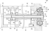
- FIG. 2 is a longitudinal cross-sectional arrow view along A-A of the tube pump illustrated in FIG. 1 .
- FIG. 3 is a longitudinal cross-sectional view illustrating a structure in which a first drive unit illustrated in FIG. 1 transmits a drive force to a first roller unit.
- FIG. 4 is a longitudinal cross-sectional view illustrating a structure in which a second drive unit illustrated in FIG. 1 transmits a drive force to a second roller unit.
- FIG. 5 is a block diagram illustrating a control configuration of the tube pump illustrated in FIG. 1 .
- FIG. 1 is a plan view illustrating an embodiment of the tube pump 100 .
- FIG. 2 is a longitudinal cross-sectional arrow view along A-A of the tube pump 100 illustrated in FIG. 1 .
- the tube pump 100 is a device that ejects a liquid, which has flowed from a flowing-in side 200 a and is stored in a tube 200 , to a flowing-out side by causing a first roller unit 10 and a second roller unit 20 to rotate about an axis X (first axis) in the same direction.
- the tube 200 with flexibility is disposed in an arc shape around the axis X in the tube pump 100 along an inner peripheral surface 82 a of a housing unit 82 that accommodates the first roller unit 10 and the second roller unit 20 .
- the inner peripheral surface 82 a is a surface, which is formed in an arc shape around the axis X, along which the tube 200 is disposed.
- the housing unit 82 has a recessed part 82 b that is opened toward one end side along the axis X and accommodates the first roller unit 10 and the second roller unit 20 .
- the first roller unit 10 and the second roller unit 20 housed in the housing unit 82 rotate around the axis X along a counter-clockwise rotation direction (a direction shown by an arrow in FIG. 1 ) while being in contact with the tube 200 .
- the tube pump 100 of the present embodiment includes a first roller unit (first contact unit) 10 and a second roller unit (second contact unit) 20 that rotate about the axis X with the tube 200 being closed, a drive shaft 30 arranged on the axis X and coupled to the first roller unit 10 , a drive cylinder 40 coupled to the second roller unit 20 , a first drive unit 50 that transmits drive force to the drive shaft 30 , a second drive unit 60 that transmits drive force to the drive cylinder 40 , and a radial bearing 70 .
- the first roller unit 10 has a first roller 11 that rotates about an axis parallel to the axis X while being in contact with the tube 200 , a first roller support member 12 coupled to the drive shaft 30 so as to integrally rotate about the axis X, and a first roller shaft 13 whose both ends are supported by the first roller support member 12 and which attaches the first roller 11 so as to be rotatable about an axis Y 1 (see FIG. 3 ).
- the first drive unit 50 transmits, to the drive shaft 30 , drive force used for rotating the first roller unit 10 in a rotation direction that is counterclockwise about the axis X.
- the first roller support member 12 is coupled to the drive shaft 30 and rotates counterclockwise about the axis while supporting the first roller 11 .
- the second roller unit 20 has a second roller 21 that rotates about an axis parallel to the axis X while being in contact with the tube 200 , a second roller support member 22 coupled to the drive cylinder 40 so as to integrally rotate about the axis X, and a second roller shaft 23 whose both ends are supported by the second roller support member 22 and which attaches the second roller 21 so as to be rotatable about an axis Y 2 (see FIG. 4 ).
- the second drive unit 60 transmits, to the drive cylinder 40 , drive force used for rotating the second roller unit 20 in a rotation direction that is counterclockwise about the axis X.
- the second roller support member 22 is coupled to the drive cylinder 40 and rotates counterclockwise about the axis while supporting the second roller 21 .
- the first drive unit 50 is fixed to a casing (not illustrated), and the second drive unit 60 is fixed by a fastening bolt 60 a to a housing unit 82 forming a part of the casing.
- the housing unit 82 is a member for housing the first roller unit 10 and the second roller unit 20 therein.
- a spacer 65 is arranged between the first drive unit 50 and the second drive unit 60 so that a first pulse motor 52 and a second pulse motor 62 described later are spaced apart from each other by a certain distance in the axis X direction.
- portions indicated by solid lines are portions forming the structure to transmit the drive force of the first drive unit 50 to the first roller unit 10 .
- the first drive unit 50 has a first drive shaft (first drive member) 51 that rotates about the axis X, the first pulse motor 52 , and a coupling member 53 .
- the coupling member 53 extending cylindrically along the axis X is fixed to the first drive shaft 51 by a locking screw 53 a . Further, the coupling member 53 is fixed to the drive shaft 30 by a locking screw 53 b.
- the first drive shaft 51 is coupled to the drive shaft 30 via the coupling member 53 .
- the first drive unit 50 rotates the drive shaft 30 in a predetermined direction about the axis X by rotating the first drive shaft 51 in a predetermined direction about the axis X by the first pulse motor 52 .
- a position detecting member 53 c that rotates about the axis X together with the coupling member 53 is attached to the coupling member 53 .
- a slit (not illustrated) for detecting the rotation position about the axis X of the first roller unit 10 is formed circumferentially about the axis X in the outer circumferential edge formed in an annular shape.
- a first position detection sensor 54 is arranged so as to interpose the outer circumferential edge of the position detecting member 53 c .
- the first position detection sensor 54 is a sensor in which a light emitting element is arranged on one of a pair of faces interposing the position detecting member 53 c and a light receiving element is arranged on the other.
- the first position detection sensor 54 detects, at the light receiving element, passage of light emitted by the light emitting element through a slit in response to rotation of the position detecting member 53 c about the axis X, thereby detects a rotation position indicating which position around the axis X the first roller unit 10 is arranged at, and transmits the detected position to a control unit 90 (see FIG. 5 ).
- the tip of the drive shaft 30 is coupled into the first roller support member 12 .
- the first roller support member 12 is fixed to an outer wheel 71 of the radial bearing 70 .
- the drive shaft 30 is supported by the radial bearing 70 rotatably about the axis X via the first roller support member 12 .
- the drive shaft 30 rotates smoothly about the axis X while maintaining the center axis on the axis X.
- the drive force by which the first drive unit 50 rotates the first drive shaft 51 about the axis X is transmitted from the first drive shaft 51 to the first roller unit 10 via the drive shaft 30 .
- portions indicated by solid lines are portions forming the structure to transmit the drive force of the second drive unit 60 to the second roller unit 20 .
- the second drive unit 60 has a second drive cylinder (second drive member) 61 arranged on the axis X and the second pulse motor 62 .
- the inner circumferential surface of the second drive cylinder 61 is fixed to the outer circumferential surface of the drive cylinder 40 .
- the second drive unit 60 rotates the second drive cylinder 61 in a predetermined direction about axis X by using the second pulse motor 62 and thereby rotates the drive cylinder 40 in a predetermined direction about the axis X.
- a position detecting member 63 that rotates about the axis X together with the drive cylinder 40 is attached to the outer circumferential surface of the drive cylinder 40 .
- a slit (not illustrated) for detecting the rotation position about the axis X of the second roller unit 20 is formed circumferentially about the axis X in the outer circumferential edge formed in an annular shape.
- a second position detection sensor 64 is arranged so as to interpose the outer circumferential edge of the position detecting member 63 .
- the second position detection sensor 64 is a sensor in which a light emitting element is arranged on one of the upper side and the under side and a light receiving element is arranged on the other of the upper side and the under side.
- the second position detection sensor 64 detects, at the light receiving element, passage of light emitted by the light emitting element through a slit in response to rotation of the position detecting member 63 about the axis X, thereby detects a rotation position indicating which position around the axis X the second roller unit 20 is arranged at, and transmits the detected position to a control unit 90 (see FIG. 5 ).
- the tip of the drive cylinder 40 is coupled to the second roller support member 22 by a locking screw 41 .
- the second roller support member 22 is fixed to an inner wheel 72 of the radial bearing 70 .
- the drive cylinder 40 is supported by the radial bearing 70 rotatably about the axis X via the second roller support member 22 .
- the drive cylinder 40 rotates smoothly about the axis X while maintaining the center axis on the axis X.
- the drive force by which the second drive unit 60 rotates the second drive cylinder 61 about the axis X is transmitted from the second drive cylinder 61 to the second roller unit 20 via the drive cylinder 40 .
- the drive shaft 30 is arranged so as to penetrate through the second pulse motor 62 of the second drive unit 60 along the axis X. Further, the drive cylinder 40 is arranged so as to penetrate through the second pulse motor 62 of the second drive unit 60 along the axis X.
- the drive shaft 30 is fixed to the outer wheel 71 of the radial bearing 70 via the first roller support member 12
- the drive cylinder 40 is fixed to the inner wheel 72 of the radial bearing 70 via the second roller support member 22 .
- the drive cylinder 40 is arranged rotatably about the axis X independently of the drive shaft 30 on the outer circumference side of the drive shaft 30 .
- the first drive unit 50 and the second drive unit 60 are arranged such that the first arrangement position of the first pulse motor 52 in the radial direction RD orthogonal to the axis X and the second arrangement position of the second pulse motor 62 match.
- the size of the tube pump 100 in the radial direction RD can be smaller than in a case where these positions do not match in the radial direction RD.
- the first arrangement position of the first pulse motor 52 and the second arrangement position of the second pulse motor 62 may be arranged so as to partially overlap each other instead of completely matching.
- FIG. 5 is a block diagram illustrating a control configuration of the tube pump 100 illustrated in FIG. 1 .
- the tube pump 100 of the present embodiment includes the control unit 90 that controls the first pulse motor 52 and the second pulse motor 62 .
- the control unit 90 of the present embodiment transmits pulse signals to the first pulse motor 52 and the second pulse motor 62 , respectively, and independently controls the first pulse motor 52 and the second pulse motor 62 , respectively.
- the control unit 90 can detect the rotation position about the axis X of the first roller unit 10 in response to receiving a signal transmitted from the first position detection sensor 54 . Further, the control unit 90 can detect the rotation position about the axis X of the second roller unit 20 in response to receiving a signal transmitted from the second position detection sensor 64 .
- the tube pump 100 of the present embodiment can implement an ejection control mode in which the control unit 90 controls the first pulse motor 52 and the second pulse motor 62 to rotate the first roller unit 10 and the second roller unit 20 in the same direction so that ejection of a liquid in the tube 200 by the first roller unit 10 and the second roller unit 20 is performed.
- the operator sets, via an input unit (not illustrated), a flow rate of a liquid to be ejected by the tube pump 100 to the flowing-out side 200 b .
- the control unit 90 controls the first pulse motor 52 and the second pulse motor 62 so that a liquid at the set flow rate is ejected to the flowing-out side 200 b.
- the control unit 90 of the present embodiment adjusts an angle difference ⁇ of the rotation position about the axis X between the first roller unit 10 and the second roller unit 20 illustrated in FIG. 1 when implementing the ejection control mode.
- the control unit 90 adjusts the angle difference ⁇ so that one of the first roller unit 10 and the second roller unit 20 comes close to the other when one of the first roller unit 10 and the second roller unit 20 is spaced away from the tube 200 .
- Such an operation can increase the pressure of a liquid inside the tube 200 closed by the first roller unit 10 and the second roller unit 20 when the one of the first roller unit 10 and the second roller unit 20 is spaced away from the tube 200 .
- the liquid is drawn from the flowing-out side 200 b to the flowing-in side 200 a of the tube 200 , and this can suppress pulsation of the liquid from occurring.
- the tube pump 100 has the first roller unit 10 and the second roller unit 20 and has the first drive unit 50 and the second drive unit 60 that rotates the first roller unit 10 and the second roller unit 20 in a predetermined direction about the axis X, respectively, and thereby the first roller unit 10 and the second roller unit 20 configured to rotate in contact with the tube 200 held in an arc shape about the axis X by the housing unit 82 can be rotated independently of each other about the axis X.
- the drive force by which the first drive unit 50 rotates the first drive shaft 51 in a predetermined direction about the axis X is transmitted to the first roller unit 10 via the drive shaft 30 penetrating through the second drive unit 60 along the axis X. Further, the drive force by which the second drive unit 60 rotates the second drive cylinder 61 in a predetermined direction about the axis X is transmitted to the second roller unit 20 via the drive cylinder 40 .
- the first drive unit 50 rotates the first drive shaft 51 coaxially with the drive shaft 30 to transmit drive force
- the second drive unit 60 rotates the second drive cylinder 61 coaxially with the drive cylinder 40 to transmit drive force.
- the tube pump 100 that can suppress vibration caused by transmission of drive force when independently driving the first roller unit 10 and the second roller unit 20 by using different drive units, respectively, to transmit the drive force from the first drive unit 50 and the second drive unit 60 to the first roller unit 10 and the second roller unit 20 and can reduce manufacturing cost.
- the first drive unit 50 having the first pulse motor 52 rotates the drive shaft 30 integrally with the first drive shaft 51
- the second drive unit 60 having the second pulse motor 62 rotates the drive cylinder 40 integrally with the second drive cylinder 61 . Since the drive shaft 30 is rotated at the same speed as the rotation speed at which the first pulse motor 52 rotates the first drive shaft 51 , the rotation speed of the first pulse motor 52 when the drive shaft 30 is rotated at a predetermined rotation speed can be smaller than in a case where the first pulse motor 52 rotates the drive shaft 30 via a reducer.
- the rotation speed of the second pulse motor 62 when the drive cylinder 40 is rotated at a predetermined rotation speed can be smaller than in a case where the second pulse motor 62 rotates the drive cylinder 40 via a reducer.
- the rotation speeds of the pulse motors when the drive shaft 30 and the drive cylinder 40 are rotated at predetermined rotation speeds it is possible to suppress a failure of step-out of the pulse motor when the drive shaft 30 and the drive cylinder 40 are rotated at a high speed.
- the first roller unit 10 coupled to the drive shaft 30 is fixed to the outer wheel 71 of the radial bearing 70
- the second roller unit 20 coupled to the drive cylinder 40 is fixed to the inner wheel 72 of the radial bearing 70 .
- the drive shaft 30 and the drive cylinder 40 are positioned relative to the outer wheel 71 and the inner wheel 72 of the radial bearing 70 , respectively. This can ensure that the drive shaft 30 and the drive cylinder 40 are arranged coaxially with each other to rotate about the axis independently without coming into contact with each other.
- the size of the tube pump 100 in the radial direction RD orthogonal to the axis X can be smaller than in a case where these positions do not overlap. This enables a smaller space in the radial direction RD required for installing the first drive unit 50 and the second drive unit 60 .
Landscapes
- Engineering & Computer Science (AREA)
- Mechanical Engineering (AREA)
- General Engineering & Computer Science (AREA)
- Reciprocating Pumps (AREA)
Abstract
Description
Claims (10)
Applications Claiming Priority (2)
| Application Number | Priority Date | Filing Date | Title |
|---|---|---|---|
| JP2021021120A JP7555113B2 (en) | 2021-02-12 | 2021-02-12 | Tube Pump |
| JP2021-021120 | 2021-02-12 |
Publications (2)
| Publication Number | Publication Date |
|---|---|
| US20220260070A1 US20220260070A1 (en) | 2022-08-18 |
| US12116990B2 true US12116990B2 (en) | 2024-10-15 |
Family
ID=80119193
Family Applications (1)
| Application Number | Title | Priority Date | Filing Date |
|---|---|---|---|
| US17/670,125 Active 2042-06-14 US12116990B2 (en) | 2021-02-12 | 2022-02-11 | Tube pump |
Country Status (4)
| Country | Link |
|---|---|
| US (1) | US12116990B2 (en) |
| EP (1) | EP4043730B1 (en) |
| JP (1) | JP7555113B2 (en) |
| KR (1) | KR20220115871A (en) |
Cited By (1)
| Publication number | Priority date | Publication date | Assignee | Title |
|---|---|---|---|---|
| US20240018963A1 (en) * | 2020-11-27 | 2024-01-18 | Paddlemover Llc | Material Mover |
Citations (8)
| Publication number | Priority date | Publication date | Assignee | Title |
|---|---|---|---|---|
| JPH07213007A (en) | 1995-01-18 | 1995-08-11 | Maruhon:Kk | Small double-axis motor |
| US5720590A (en) * | 1993-04-16 | 1998-02-24 | Brooks Automation, Inc. | Articulated arm transfer device |
| US6145889A (en) * | 1999-01-13 | 2000-11-14 | Surpass Industry Co., Ltd | Rotary joint |
| US20020074891A1 (en) * | 2000-12-18 | 2002-06-20 | Otis Elevator Company | Fabricated components of transverse flux electric motors |
| WO2005080794A1 (en) | 2004-02-24 | 2005-09-01 | Seiko Instruments Inc. | Tube pump and ink jet recorder using the same |
| US7960883B2 (en) * | 2009-01-28 | 2011-06-14 | Minebea Motor Manufacturing Corporation | Motor assembly with coaxial shafts |
| JP2017067054A (en) | 2015-10-02 | 2017-04-06 | サーパス工業株式会社 | Tube pump |
| EP3296570B1 (en) | 2016-09-14 | 2020-10-28 | Surpass Industry Co., Ltd. | Tube pump system and method for controlling the tube pump system |
-
2021
- 2021-02-12 JP JP2021021120A patent/JP7555113B2/en active Active
-
2022
- 2022-02-02 EP EP22154706.0A patent/EP4043730B1/en active Active
- 2022-02-07 KR KR1020220015437A patent/KR20220115871A/en active Pending
- 2022-02-11 US US17/670,125 patent/US12116990B2/en active Active
Patent Citations (10)
| Publication number | Priority date | Publication date | Assignee | Title |
|---|---|---|---|---|
| US5720590A (en) * | 1993-04-16 | 1998-02-24 | Brooks Automation, Inc. | Articulated arm transfer device |
| JPH07213007A (en) | 1995-01-18 | 1995-08-11 | Maruhon:Kk | Small double-axis motor |
| US6145889A (en) * | 1999-01-13 | 2000-11-14 | Surpass Industry Co., Ltd | Rotary joint |
| US20020074891A1 (en) * | 2000-12-18 | 2002-06-20 | Otis Elevator Company | Fabricated components of transverse flux electric motors |
| WO2005080794A1 (en) | 2004-02-24 | 2005-09-01 | Seiko Instruments Inc. | Tube pump and ink jet recorder using the same |
| US7960883B2 (en) * | 2009-01-28 | 2011-06-14 | Minebea Motor Manufacturing Corporation | Motor assembly with coaxial shafts |
| JP2017067054A (en) | 2015-10-02 | 2017-04-06 | サーパス工業株式会社 | Tube pump |
| US20170096995A1 (en) * | 2015-10-02 | 2017-04-06 | Surpass Industry Co., Ltd. | Tube pump |
| EP3171027B1 (en) | 2015-10-02 | 2020-01-29 | Surpass Industry Co., Ltd. | Tube pump |
| EP3296570B1 (en) | 2016-09-14 | 2020-10-28 | Surpass Industry Co., Ltd. | Tube pump system and method for controlling the tube pump system |
Non-Patent Citations (2)
| Title |
|---|
| Extended European Search Report for European Application No. 22154706.0 dated Jul. 6, 2022. |
| Office Action for Japanese Patent Application No. 2021-021120 dated May 14, 2024. |
Cited By (1)
| Publication number | Priority date | Publication date | Assignee | Title |
|---|---|---|---|---|
| US20240018963A1 (en) * | 2020-11-27 | 2024-01-18 | Paddlemover Llc | Material Mover |
Also Published As
| Publication number | Publication date |
|---|---|
| EP4043730A1 (en) | 2022-08-17 |
| JP7555113B2 (en) | 2024-09-24 |
| US20220260070A1 (en) | 2022-08-18 |
| EP4043730B1 (en) | 2024-07-17 |
| JP2022123669A (en) | 2022-08-24 |
| KR20220115871A (en) | 2022-08-19 |
Similar Documents
| Publication | Publication Date | Title |
|---|---|---|
| KR102465743B1 (en) | Tube Pump | |
| US12116990B2 (en) | Tube pump | |
| US12221956B2 (en) | Tube pump | |
| EP2913557A1 (en) | Planet roller speed changer | |
| US20140262676A1 (en) | Driving force transmitting apparatus | |
| KR101789820B1 (en) | Angle sensor | |
| GB2117572A (en) | Motor with a position sensor | |
| US9664188B2 (en) | Variable displacement vane pump | |
| JP4843364B2 (en) | Flow machine, sliding ring seal thereof, body part of the sliding ring seal, and method of fastening the sliding ring seal to the flow machine | |
| US12454416B2 (en) | Motor cartridge for roller, roller | |
| JP4901661B2 (en) | Pump device and power steering device to which this pump device is applied | |
| US11536268B2 (en) | Electric pump | |
| KR20250052143A (en) | Actuator for controlling flow-rate | |
| US11306710B2 (en) | Pump device | |
| EP2208891B1 (en) | Minipump | |
| CN222991683U (en) | Peristaltic pump | |
| US20030219336A1 (en) | Reversible volumetric machine | |
| US20240263627A1 (en) | Tube pump | |
| US20190309769A1 (en) | Hydraulic drive device | |
| KR20010044680A (en) | A rotor device for a vacuum suction type-notecounter | |
| KR200220602Y1 (en) | Power steering system for vehicle | |
| KR20010066551A (en) | Device for controlling amount of flow of pump for power steering device | |
| JP2021129362A (en) | Power transmission device | |
| WO2001065142A1 (en) | Gear drive transmission and method | |
| KR19980061158A (en) | Motor oil steering pump |
Legal Events
| Date | Code | Title | Description |
|---|---|---|---|
| AS | Assignment |
Owner name: SURPASS INDUSTRY CO., LTD., JAPAN Free format text: ASSIGNMENT OF ASSIGNORS INTEREST;ASSIGNOR:IMAI, HIROSHI;REEL/FRAME:059084/0267 Effective date: 20220121 |
|
| FEPP | Fee payment procedure |
Free format text: ENTITY STATUS SET TO UNDISCOUNTED (ORIGINAL EVENT CODE: BIG.); ENTITY STATUS OF PATENT OWNER: SMALL ENTITY |
|
| FEPP | Fee payment procedure |
Free format text: ENTITY STATUS SET TO SMALL (ORIGINAL EVENT CODE: SMAL); ENTITY STATUS OF PATENT OWNER: SMALL ENTITY |
|
| STPP | Information on status: patent application and granting procedure in general |
Free format text: DOCKETED NEW CASE - READY FOR EXAMINATION |
|
| STPP | Information on status: patent application and granting procedure in general |
Free format text: NON FINAL ACTION MAILED |
|
| STPP | Information on status: patent application and granting procedure in general |
Free format text: RESPONSE TO NON-FINAL OFFICE ACTION ENTERED AND FORWARDED TO EXAMINER |
|
| STPP | Information on status: patent application and granting procedure in general |
Free format text: FINAL REJECTION MAILED |
|
| STPP | Information on status: patent application and granting procedure in general |
Free format text: RESPONSE AFTER FINAL ACTION FORWARDED TO EXAMINER |
|
| STPP | Information on status: patent application and granting procedure in general |
Free format text: NOTICE OF ALLOWANCE MAILED -- APPLICATION RECEIVED IN OFFICE OF PUBLICATIONS |
|
| STPP | Information on status: patent application and granting procedure in general |
Free format text: NOTICE OF ALLOWANCE MAILED -- APPLICATION RECEIVED IN OFFICE OF PUBLICATIONS |
|
| STPP | Information on status: patent application and granting procedure in general |
Free format text: PUBLICATIONS -- ISSUE FEE PAYMENT VERIFIED |
|
| STCF | Information on status: patent grant |
Free format text: PATENTED CASE |